

Page 1

Service
GETtheMANUALS.org
Workshop Manual
Rapid NH 2013 ➤
Rapid NH 2014 ➤
Electrical system
Edition 02.2018
Service Department. Technical Information
Page 2

List of Workshop Manual Repair Groups
GETtheMANUALS.org
Re pa ir G ro up
00 - Technical data
27 - Starter, current supply, CCS
90 - Gauges, instruments
91 - Radio, telephone, navigation
92 - Windscreen wash/wipe system
94 - Lights, bulbs, switches - exterior
96 - Lights, bulbs, switches - interior
97 - Wiring
Service
Technical information should always be available to the foremen and mechanics, because their
careful and constant adherence to the instructions is essential to ensure vehicle road-worthiness and
safety. In addition, the normal basic safety precautions for working on motor vehicles must, as a
matter of course, be observed.
Page 3

Contents
GETtheMANUALS.org
Rapid NH 2013 ➤ , Rapid NH 2014 ➤
Electrical system - Edition 02.2018
00 - Technical data
1 Safety instructions
1.1 Safety precautions when working on vehicles with a start/stop system . . . . . . . . . . . . . . . . 1
1.2 Safety precautions during road tests in which testing and measuring equipment is used . . 1
1.3 Use and safety instructions for gas discharge lamps . . . . . . . . . . . . . . . . . . . . . . . . . . . . . . 1
2 Repair instructions . . . . . . . . . . . . . . . . . . . . . . . . . . . . . . . . . . . . . . . . . . . . . . . . . . . . . . . . 3
2.1 Contact corrosion . . . . . . . . . . . . . . . . . . . . . . . . . . . . . . . . . . . . . . . . . . . . . . . . . . . . . . . . 3
2.2 Cable routing and securing . . . . . . . . . . . . . . . . . . . . . . . . . . . . . . . . . . . . . . . . . . . . . . . . 3
3 Battery . . . . . . . . . . . . . . . . . . . . . . . . . . . . . . . . . . . . . . . . . . . . . . . . . . . . . . . . . . . . . . . . 5
3.1 Warning instructions and safety precautions when working on the battery . . . . . . . . . . . . 5
3.2 Battery types . . . . . . . . . . . . . . . . . . . . . . . . . . . . . . . . . . . . . . . . . . . . . . . . . . . . . . . . . . . . 5
27 - Starter, current supply, CCS
1 Battery
1.1 Assembly overview - battery . . . . . . . . . . . . . . . . . . . . . . . . . . . . . . . . . . . . . . . . . . . . . . . . 6
1.2 Summary of components - battery isolation . . . . . . . . . . . . . . . . . . . . . . . . . . . . . . . . . . . . 10
1.3 Disconnecting and reconnecting battery . . . . . . . . . . . . . . . . . . . . . . . . . . . . . . . . . . . . . . 10
1.4 Checking battery . . . . . . . . . . . . . . . . . . . . . . . . . . . . . . . . . . . . . . . . . . . . . . . . . . . . . . . . 13
1.5 Charging battery . . . . . . . . . . . . . . . . . . . . . . . . . . . . . . . . . . . . . . . . . . . . . . . . . . . . . . . . . . 13
1.6 Removing and installing battery . . . . . . . . . . . . . . . . . . . . . . . . . . . . . . . . . . . . . . . . . . . . . . 13
1.7 Removing and installing earth lead with battery monitoring control unit J367 . . . . . . . . . . 17
1.8 Removing and installing battery isolation . . . . . . . . . . . . . . . . . . . . . . . . . . . . . . . . . . . . . . 18
1.9 Battery parameterisation . . . . . . . . . . . . . . . . . . . . . . . . . . . . . . . . . . . . . . . . . . . . . . . . . . 19
1.10 Removing and installing battery tray . . . . . . . . . . . . . . . . . . . . . . . . . . . . . . . . . . . . . . . . . . 19
2 Jump start point . . . . . . . . . . . . . . . . . . . . . . . . . . . . . . . . . . . . . . . . . . . . . . . . . . . . . . . . . . 23
2.1 Summary of components - jump start point . . . . . . . . . . . . . . . . . . . . . . . . . . . . . . . . . . . . 23
2.2 Removing and installing jump start point . . . . . . . . . . . . . . . . . . . . . . . . . . . . . . . . . . . . . . 23
3 Starter . . . . . . . . . . . . . . . . . . . . . . . . . . . . . . . . . . . . . . . . . . . . . . . . . . . . . . . . . . . . . . . . . . 25
3.1 Assembly overview: starter . . . . . . . . . . . . . . . . . . . . . . . . . . . . . . . . . . . . . . . . . . . . . . . . 25
3.2 Removing and installing starter . . . . . . . . . . . . . . . . . . . . . . . . . . . . . . . . . . . . . . . . . . . . . . 29
3.3 Checking starter . . . . . . . . . . . . . . . . . . . . . . . . . . . . . . . . . . . . . . . . . . . . . . . . . . . . . . . . . . 36
4 Alternator . . . . . . . . . . . . . . . . . . . . . . . . . . . . . . . . . . . . . . . . . . . . . . . . . . . . . . . . . . . . . . 37
4.1 Removing and installing alternator . . . . . . . . . . . . . . . . . . . . . . . . . . . . . . . . . . . . . . . . . . . . 37
4.2 Fixing the B+ wire to the AC generator . . . . . . . . . . . . . . . . . . . . . . . . . . . . . . . . . . . . . . . . 39
4.3 Checking the carbon brushes of the AC generator . . . . . . . . . . . . . . . . . . . . . . . . . . . . . . 39
4.4 Removing and installing voltage regulator . . . . . . . . . . . . . . . . . . . . . . . . . . . . . . . . . . . . . . 40
4.5 Removing and installing V-ribbed belt pulley on alternator . . . . . . . . . . . . . . . . . . . . . . . . 41
5 start-stop system . . . . . . . . . . . . . . . . . . . . . . . . . . . . . . . . . . . . . . . . . . . . . . . . . . . . . . . . 47
5.1 Safety precautions for vehicles with start-stop system . . . . . . . . . . . . . . . . . . . . . . . . . . . . 47
5.2 General description . . . . . . . . . . . . . . . . . . . . . . . . . . . . . . . . . . . . . . . . . . . . . . . . . . . . . . 47
5.3 Fault recognition and fault display . . . . . . . . . . . . . . . . . . . . . . . . . . . . . . . . . . . . . . . . . . . . 48
5.4 Battery recharging or starting by external source on vehicles with start-stop system . . . . 48
5.5 Replacing the battery on vehicles with “start-stop” system . . . . . . . . . . . . . . . . . . . . . . . . 48
5.6 Voltage stabiliser J532 . . . . . . . . . . . . . . . . . . . . . . . . . . . . . . . . . . . . . . . . . . . . . . . . . . . . 49
5.7 Battery monitor control unit J367 . . . . . . . . . . . . . . . . . . . . . . . . . . . . . . . . . . . . . . . . . . . . 49
5.8 Button for start-stop system . . . . . . . . . . . . . . . . . . . . . . . . . . . . . . . . . . . . . . . . . . . . . . . . 50
6 Front Assistant . . . . . . . . . . . . . . . . . . . . . . . . . . . . . . . . . . . . . . . . . . . . . . . . . . . . . . . . . . 51
6.1 Installation location overview - Front Assistant . . . . . . . . . . . . . . . . . . . . . . . . . . . . . . . . . . 51
6.2 Removing and installing front assistant system control unit . . . . . . . . . . . . . . . . . . . . . . . . 52
6.3 Removing and installing the retaining plate of the front assistant system control unit . . . . 52
6.4 Calibrating the front assistant system . . . . . . . . . . . . . . . . . . . . . . . . . . . . . . . . . . . . . . . . 54
. . . . . . . . . . . . . . . . . . . . . . . . . . . . . . . . . . . . . . . . . . . . . . . . . . . . 1
. . . . . . . . . . . . . . . . . . . . . . . . . . . . . . . . . . . . . . . . . . . . . . . . . . . . . . . . 1
. . . . . . . . . . . . . . . . . . . . . . . . . . . . . . . . . . . . . . . . 6
. . . . . . . . . . . . . . . . . . . . . . . . . . . . . . . . . . . . . . . . . . . . . . . . . . . . . . . . . . . . . . . . 6
Contents i
Page 4

Rapid NH 2013 ➤ , Rapid NH 2014 ➤
GETtheMANUALS.org
Electrical system - Edition 02.2018
90 - Gauges, instruments
1 Dash panel insert
1.1 General description . . . . . . . . . . . . . . . . . . . . . . . . . . . . . . . . . . . . . . . . . . . . . . . . . . . . . . 55
1.2 The self-diagnostic function of the dash panel insert . . . . . . . . . . . . . . . . . . . . . . . . . . . . . . 56
1.3 Adjust/replace dash panel insert . . . . . . . . . . . . . . . . . . . . . . . . . . . . . . . . . . . . . . . . . . . . 56
1.4 Removing and installing the dash panel insert . . . . . . . . . . . . . . . . . . . . . . . . . . . . . . . . . . 56
1.5 Contact assignment of plug connection on the dash panel insert . . . . . . . . . . . . . . . . . . . . 57
1.6 Warning lights in the dash panel insert . . . . . . . . . . . . . . . . . . . . . . . . . . . . . . . . . . . . . . . . 57
1.7 Service interval display . . . . . . . . . . . . . . . . . . . . . . . . . . . . . . . . . . . . . . . . . . . . . . . . . . . . 58
2 Cruise control system (CCS) . . . . . . . . . . . . . . . . . . . . . . . . . . . . . . . . . . . . . . . . . . . . . . . . 59
91 - Radio, telephone, navigation
1 Radio - installed up to CW 21.2015
1.1 General Instructions . . . . . . . . . . . . . . . . . . . . . . . . . . . . . . . . . . . . . . . . . . . . . . . . . . . . . . 60
1.2 Electronic anti-theft coding . . . . . . . . . . . . . . . . . . . . . . . . . . . . . . . . . . . . . . . . . . . . . . . . . . 60
1.3 Summary of components - radio . . . . . . . . . . . . . . . . . . . . . . . . . . . . . . . . . . . . . . . . . . . . 61
1.4 Removing and installing a radio . . . . . . . . . . . . . . . . . . . . . . . . . . . . . . . . . . . . . . . . . . . . 62
1.5 Plug connections on the radio . . . . . . . . . . . . . . . . . . . . . . . . . . . . . . . . . . . . . . . . . . . . . . 64
1.6 Self-diagnostic function of radio system . . . . . . . . . . . . . . . . . . . . . . . . . . . . . . . . . . . . . . . . 64
2 Amundsen+ navigation system - installed up to CW 21.2015 . . . . . . . . . . . . . . . . . . . . . . 65
2.1 General description . . . . . . . . . . . . . . . . . . . . . . . . . . . . . . . . . . . . . . . . . . . . . . . . . . . . . . 65
2.2 General Instructions . . . . . . . . . . . . . . . . . . . . . . . . . . . . . . . . . . . . . . . . . . . . . . . . . . . . . . 65
2.3 Electronic anti-theft coding . . . . . . . . . . . . . . . . . . . . . . . . . . . . . . . . . . . . . . . . . . . . . . . . . . 65
2.4 Overall view of the navigation system . . . . . . . . . . . . . . . . . . . . . . . . . . . . . . . . . . . . . . . . 66
2.5 Removing and installing the navigation system . . . . . . . . . . . . . . . . . . . . . . . . . . . . . . . . . . 68
2.6 Plug connections on the navigation system . . . . . . . . . . . . . . . . . . . . . . . . . . . . . . . . . . . . 69
2.7 Aerial for GPS signal reception . . . . . . . . . . . . . . . . . . . . . . . . . . . . . . . . . . . . . . . . . . . . . . 69
2.8 Diagnosis of the navigation system . . . . . . . . . . . . . . . . . . . . . . . . . . . . . . . . . . . . . . . . . . 69
3 Infotainment system - installed as of CW 22.2015 . . . . . . . . . . . . . . . . . . . . . . . . . . . . . . . . 70
3.1 Infotainment system - general notes . . . . . . . . . . . . . . . . . . . . . . . . . . . . . . . . . . . . . . . . . . 70
3.2 Summary of components - Infotainment system . . . . . . . . . . . . . . . . . . . . . . . . . . . . . . . . 70
3.3 Installation – Infotainment system . . . . . . . . . . . . . . . . . . . . . . . . . . . . . . . . . . . . . . . . . . . . 72
3.4 Removing and installing the Infotainment display/control unit . . . . . . . . . . . . . . . . . . . . . . 74
3.5 Remove and install infotainment display unit . . . . . . . . . . . . . . . . . . . . . . . . . . . . . . . . . . . . 77
3.6 Removing and installing the infotainment control unit . . . . . . . . . . . . . . . . . . . . . . . . . . . . 78
3.7 Electronic anti-theft coding . . . . . . . . . . . . . . . . . . . . . . . . . . . . . . . . . . . . . . . . . . . . . . . . . . 79
3.8 “Basic” (Blues) infotainment - initial setup, self-diagnosis . . . . . . . . . . . . . . . . . . . . . . . . . . 80
4 Replacing aerials, aerial modules and aerial cables . . . . . . . . . . . . . . . . . . . . . . . . . . . . . . 82
4.1 Summary of components, Rapid . . . . . . . . . . . . . . . . . . . . . . . . . . . . . . . . . . . . . . . . . . . . 82
4.2 Removing and installing roof aerial . . . . . . . . . . . . . . . . . . . . . . . . . . . . . . . . . . . . . . . . . . 85
4.3 Removing and installing the GPS aerial . . . . . . . . . . . . . . . . . . . . . . . . . . . . . . . . . . . . . . . . 87
4.4 Removing and installing the GSM aerial . . . . . . . . . . . . . . . . . . . . . . . . . . . . . . . . . . . . . . 88
4.5 Rear or side window aerial (Spaceback) . . . . . . . . . . . . . . . . . . . . . . . . . . . . . . . . . . . . . . 89
4.6 Panoramic roof aerial . . . . . . . . . . . . . . . . . . . . . . . . . . . . . . . . . . . . . . . . . . . . . . . . . . . . . . 89
4.7 Aerial module R254 for rear window aerial . . . . . . . . . . . . . . . . . . . . . . . . . . . . . . . . . . . . 89
4.8 Aerial module for rear left side window aerial . . . . . . . . . . . . . . . . . . . . . . . . . . . . . . . . . . . . 90
4.9 Aerial module for panoramic roof aerial . . . . . . . . . . . . . . . . . . . . . . . . . . . . . . . . . . . . . . . . 90
4.10 Replacing aerial cables . . . . . . . . . . . . . . . . . . . . . . . . . . . . . . . . . . . . . . . . . . . . . . . . . . . . 91
5 Telephone system . . . . . . . . . . . . . . . . . . . . . . . . . . . . . . . . . . . . . . . . . . . . . . . . . . . . . . . . 92
5.1 Mobile phone pre-installation . . . . . . . . . . . . . . . . . . . . . . . . . . . . . . . . . . . . . . . . . . . . . . . . 92
5.2 Removing and installing the control unit for the mobile phone operating electronics J412
. . . . . . . . . . . . . . . . . . . . . . . . . . . . . . . . . . . . . . . . . . . . . . . . . . . . . . . . . . . . . . . . . . . . . . . . 92
5.3 Removing and installing the microphone for the telephone R38 . . . . . . . . . . . . . . . . . . . . 93
6 Multi-functional steering wheel . . . . . . . . . . . . . . . . . . . . . . . . . . . . . . . . . . . . . . . . . . . . . . 94
. . . . . . . . . . . . . . . . . . . . . . . . . . . . . . . . . . . . . . . . . . . . . . 55
. . . . . . . . . . . . . . . . . . . . . . . . . . . . . . . . . . . . . . . . . . . . . . . . . . . . . . . . 55
. . . . . . . . . . . . . . . . . . . . . . . . . . . . . . . . . . . . . . . . 60
. . . . . . . . . . . . . . . . . . . . . . . . . . . . . . . . . . . . . . . . . . 60
ii Contents
Page 5

Rapid NH 2013 ➤ , Rapid NH 2014 ➤
GETtheMANUALS.org
Electrical system - Edition 02.2018
6.1 Multi-functional steering wheel - general instructions . . . . . . . . . . . . . . . . . . . . . . . . . . . . . . 94
6.2 Removing and installing switch unit for operating the radio and phone/infotainment . . . . . . 94
6.3 Diagnosis of the multi-functional steering wheel
7 Multimedia socket MEDIA-IN . . . . . . . . . . . . . . . . . . . . . . . . . . . . . . . . . . . . . . . . . . . . . . . . 96
7.1 General description . . . . . . . . . . . . . . . . . . . . . . . . . . . . . . . . . . . . . . . . . . . . . . . . . . . . . . 96
7.2 Removing and installing the control unit for multimedia system J650 . . . . . . . . . . . . . . . . 96
7.3 Removing and installing connection for external audio sources R199 (AUX-IN, USB) . . . . 97
7.4 Removing and installing the rear USB charging module . . . . . . . . . . . . . . . . . . . . . . . . . . 98
8 Loudspeaker arrangement . . . . . . . . . . . . . . . . . . . . . . . . . . . . . . . . . . . . . . . . . . . . . . . . . . 99
8.1 Removing and installing front bass speaker and rear full-range speaker . . . . . . . . . . . . . . 99
8.2 Removing and installing the front treble speaker . . . . . . . . . . . . . . . . . . . . . . . . . . . . . . . . 99
9 SmartLink system . . . . . . . . . . . . . . . . . . . . . . . . . . . . . . . . . . . . . . . . . . . . . . . . . . . . . . . . 101
9.1 SmartLink system - general instructions . . . . . . . . . . . . . . . . . . . . . . . . . . . . . . . . . . . . . . 101
10 SmartGate system . . . . . . . . . . . . . . . . . . . . . . . . . . . . . . . . . . . . . . . . . . . . . . . . . . . . . . . . 102
10.1 SmartGate system - general notes . . . . . . . . . . . . . . . . . . . . . . . . . . . . . . . . . . . . . . . . . . . . 102
10.2 SmartGate system - check the correct function . . . . . . . . . . . . . . . . . . . . . . . . . . . . . . . . . . 103
10.3 Removing and installing the control unit for wireless data transfer J1070 (SmartGate) . . . . 104
10.4 Set the parameters for the WLAN connection . . . . . . . . . . . . . . . . . . . . . . . . . . . . . . . . . . 105
10.5 Update firmware . . . . . . . . . . . . . . . . . . . . . . . . . . . . . . . . . . . . . . . . . . . . . . . . . . . . . . . . . . 106
11 Mobile services online . . . . . . . . . . . . . . . . . . . . . . . . . . . . . . . . . . . . . . . . . . . . . . . . . . . . 108
11.1 General Instructions . . . . . . . . . . . . . . . . . . . . . . . . . . . . . . . . . . . . . . . . . . . . . . . . . . . . . . 108
11.2 Installation location overview - mobile online services . . . . . . . . . . . . . . . . . . . . . . . . . . . . 108
11.3 Removing and installing control unit for emergency call module and communication unit J949
. . . . . . . . . . . . . . . . . . . . . . . . . . . . . . . . . . . . . . . . . . . . . . . . . . . . . . . . . . . . . . . . . . . . . . 110
11.4 Removing and installing emergency call button E276 . . . . . . . . . . . . . . . . . . . . . . . . . . . . 111
11.5 Removing and installing speaker for emergency call module R335 . . . . . . . . . . . . . . . . . . 111
11.6 Replacing battery for control unit for emergency call module and communication unit J949
. . . . . . . . . . . . . . . . . . . . . . . . . . . . . . . . . . . . . . . . . . . . . . . . . . . . . . . . . . . . . . . . . . . . . . . . 111
11.7 Replacing, adapting and activating control unit for emergency call module and
communication unit J949 . . . . . . . . . . . . . . . . . . . . . . . . . . . . . . . . . . . . . . . . . . . . . . . . . . 112
11.8 Checking that the components and communication of the ERA Glonass system are
functioning . . . . . . . . . . . . . . . . . . . . . . . . . . . . . . . . . . . . . . . . . . . . . . . . . . . . . . . . . . . . . . 114
. . . . . . . . . . . . . . . . . . . . . . . . . . . . . . . . 95
92 - Windscreen wash/wipe system
1 Windscreen washer system
1.1 Removing and installing washer fluid reservoir, washer fluid pumps and sensor for washer
fluid level . . . . . . . . . . . . . . . . . . . . . . . . . . . . . . . . . . . . . . . . . . . . . . . . . . . . . . . . . . . . . . 116
1.2 Removing and installing the spray nozzles for windscreen washer system . . . . . . . . . . . . 117
1.3 Repairing washer fluid lines . . . . . . . . . . . . . . . . . . . . . . . . . . . . . . . . . . . . . . . . . . . . . . . . 117
2 Windscreen wiper and washer system . . . . . . . . . . . . . . . . . . . . . . . . . . . . . . . . . . . . . . . . 118
2.1 Removing and installing the wiper arms with wiper blades and setting their final setting . . 118
2.2 Removing and installing wiper motor with linkage . . . . . . . . . . . . . . . . . . . . . . . . . . . . . . . . 119
2.3 Removing and installing windscreen wiper motor from linkage . . . . . . . . . . . . . . . . . . . . . . 120
2.4 Removing and installing sensor for rain and light detection G397 , vehicles up to CW
21.2015 . . . . . . . . . . . . . . . . . . . . . . . . . . . . . . . . . . . . . . . . . . . . . . . . . . . . . . . . . . . . . . . . 121
2.5 Removing and installing sensor for rain and light detection G397 , vehicles from CW
22.2015 . . . . . . . . . . . . . . . . . . . . . . . . . . . . . . . . . . . . . . . . . . . . . . . . . . . . . . . . . . . . . . . . 123
2.6 Repairing sensor for rain and light detection G397 , vehicles from CW 22.2015 . . . . . . . . 125
3 Rear window wiper and washer system . . . . . . . . . . . . . . . . . . . . . . . . . . . . . . . . . . . . . . . . 129
3.1 Removing and installing the wiper arm with wiper blade and setting its final setting . . . . . . 129
3.2 Removing and installing windscreen wiper motor . . . . . . . . . . . . . . . . . . . . . . . . . . . . . . . . 130
3.3 Replacing and adjusting the spray nozzle. . . . . . . . . . . . . . . . . . . . . . . . . . . . . . . . . . . . . 131
4 Headlamp cleaning system . . . . . . . . . . . . . . . . . . . . . . . . . . . . . . . . . . . . . . . . . . . . . . . . 133
4.1 Removing and installing headlight cleaning system pump V11 . . . . . . . . . . . . . . . . . . . . 133
4.2 Removing and installing the lift cylinder for spray nozzles of headlight . . . . . . . . . . . . . . . . 133
4.3 Bleed the headlamp cleaning system . . . . . . . . . . . . . . . . . . . . . . . . . . . . . . . . . . . . . . . . . . 133
. . . . . . . . . . . . . . . . . . . . . . . . . . . . . . . . . . . . . . 116
. . . . . . . . . . . . . . . . . . . . . . . . . . . . . . . . . . . . . . . . . . . . . . . . 116
Contents iii
Page 6

Rapid NH 2013 ➤ , Rapid NH 2014 ➤
GETtheMANUALS.org
Electrical system - Edition 02.2018
94 - Lights, bulbs, switches - exterior
1 Headlights – halogen headlights
1.1 Summary of components, halogen headlight . . . . . . . . . . . . . . . . . . . . . . . . . . . . . . . . . . . . 135
1.2 Removing and installing headlight . . . . . . . . . . . . . . . . . . . . . . . . . . . . . . . . . . . . . . . . . . . . 138
1.3 Replacing light bulbs in headlights . . . . . . . . . . . . . . . . . . . . . . . . . . . . . . . . . . . . . . . . . . . . 139
1.4 Removing and installing headlight range control motor . . . . . . . . . . . . . . . . . . . . . . . . . . . . 143
1.5 Replace headlight fixing brackets . . . . . . . . . . . . . . . . . . . . . . . . . . . . . . . . . . . . . . . . . . . . 144
1.6 Removing and installing LED module . . . . . . . . . . . . . . . . . . . . . . . . . . . . . . . . . . . . . . . . 144
1.7 Change headlight for right-hand and/or left-hand traffic . . . . . . . . . . . . . . . . . . . . . . . . . . . . 145
1.8 Setting the headlight beam . . . . . . . . . . . . . . . . . . . . . . . . . . . . . . . . . . . . . . . . . . . . . . . . . . 146
2 Headlights with Xenon discharge lamps . . . . . . . . . . . . . . . . . . . . . . . . . . . . . . . . . . . . . . 147
2.1 Summary of components, headlights with Xenon discharge lamps . . . . . . . . . . . . . . . . . . 147
2.2 Removing and installing headlight . . . . . . . . . . . . . . . . . . . . . . . . . . . . . . . . . . . . . . . . . . . . 150
2.3 Replacing light bulbs and gas discharge lamps . . . . . . . . . . . . . . . . . . . . . . . . . . . . . . . . . . 150
2.4 Replace attachment brackets . . . . . . . . . . . . . . . . . . . . . . . . . . . . . . . . . . . . . . . . . . . . . . . . 154
2.5 Removing and installing headlight range control motor . . . . . . . . . . . . . . . . . . . . . . . . . . . . 155
2.6 Removing and installing the power output module for headlight . . . . . . . . . . . . . . . . . . . . 157
2.7 Removing and installing LED module . . . . . . . . . . . . . . . . . . . . . . . . . . . . . . . . . . . . . . . . 157
2.8 Change headlight for right-hand and/or left-hand traffic . . . . . . . . . . . . . . . . . . . . . . . . . . . . 158
2.9 Setting the headlight beam . . . . . . . . . . . . . . . . . . . . . . . . . . . . . . . . . . . . . . . . . . . . . . . . . . 159
3 Side turn signal in the wing . . . . . . . . . . . . . . . . . . . . . . . . . . . . . . . . . . . . . . . . . . . . . . . . 160
3.1 Removing and installing side turn signal in the wing . . . . . . . . . . . . . . . . . . . . . . . . . . . . . . 160
4 Lights in the exterior mirror . . . . . . . . . . . . . . . . . . . . . . . . . . . . . . . . . . . . . . . . . . . . . . . . . . 161
4.1 Removing and installing the turn signal light in the exterior mirror . . . . . . . . . . . . . . . . . . . . 161
4.2 Removing and installing signal bulb in exterior mirror L131 / L132 . . . . . . . . . . . . . . . . . . 161
5 Tail lights . . . . . . . . . . . . . . . . . . . . . . . . . . . . . . . . . . . . . . . . . . . . . . . . . . . . . . . . . . . . . . 163
5.1 Removing and installing tail light . . . . . . . . . . . . . . . . . . . . . . . . . . . . . . . . . . . . . . . . . . . . 163
5.2 Replacing the light bulbs of the tail light . . . . . . . . . . . . . . . . . . . . . . . . . . . . . . . . . . . . . . . . 163
6 Registration number lighting . . . . . . . . . . . . . . . . . . . . . . . . . . . . . . . . . . . . . . . . . . . . . . . . 165
6.1 Removing and installing licence plate carrier . . . . . . . . . . . . . . . . . . . . . . . . . . . . . . . . . . . . 165
6.2 Replacing bulb for the number plate light . . . . . . . . . . . . . . . . . . . . . . . . . . . . . . . . . . . . . . 165
7 Additional brake light . . . . . . . . . . . . . . . . . . . . . . . . . . . . . . . . . . . . . . . . . . . . . . . . . . . . . . 167
7.1 Removing and installing high level brake light . . . . . . . . . . . . . . . . . . . . . . . . . . . . . . . . . . 167
8 Fog lights, fog lights with “Corner” function and daylight driving light . . . . . . . . . . . . . . . . 170
8.1 General description, fault recognition and fault display . . . . . . . . . . . . . . . . . . . . . . . . . . . . 170
8.2 Removing and installing fog light . . . . . . . . . . . . . . . . . . . . . . . . . . . . . . . . . . . . . . . . . . . . 170
8.3 Adjusting the fog light . . . . . . . . . . . . . . . . . . . . . . . . . . . . . . . . . . . . . . . . . . . . . . . . . . . . . . 171
8.4 Replacing light bulb for fog light . . . . . . . . . . . . . . . . . . . . . . . . . . . . . . . . . . . . . . . . . . . . . . 171
9 Entry and start authorisation . . . . . . . . . . . . . . . . . . . . . . . . . . . . . . . . . . . . . . . . . . . . . . . . 173
9.1 Installation overview - entry and start authorisation . . . . . . . . . . . . . . . . . . . . . . . . . . . . . . 173
9.2 Install and remove interior aerial 1 for entry and start system R138 . . . . . . . . . . . . . . . . . . 174
9.3 Install and remove aerial in luggage compartment for entry and start system R137 . . . . 175
9.4 Install and remove aerial in rear bumper for entry and start system R136 . . . . . . . . . . . . 175
9.5 Control unit for keyless entry authorisation . . . . . . . . . . . . . . . . . . . . . . . . . . . . . . . . . . . . 176
9.6 Connection assignment of the connector on the control unit for keyless entry authorisation
. . . . . . . . . . . . . . . . . . . . . . . . . . . . . . . . . . . . . . . . . . . . . . . . . . . . . . . . . . . . . . . . . . . . . . . . 177
10 Switch unit on the steering column . . . . . . . . . . . . . . . . . . . . . . . . . . . . . . . . . . . . . . . . . . . . 178
10.1 Summary of components - switch unit on the steering column . . . . . . . . . . . . . . . . . . . . . . 178
10.2 Removing and installing steering column combination switch . . . . . . . . . . . . . . . . . . . . . . 181
10.3 Removing and installing return ring with slip ring from steering column combination switch
. . . . . . . . . . . . . . . . . . . . . . . . . . . . . . . . . . . . . . . . . . . . . . . . . . . . . . . . . . . . . . . . . . . . . . . . 184
10.4 Adjusting centre position for return ring with slip ring . . . . . . . . . . . . . . . . . . . . . . . . . . . . . . 185
10.5 Removing and installing steering lock housing . . . . . . . . . . . . . . . . . . . . . . . . . . . . . . . . . . 186
10.6 Removing and installing lock cylinder . . . . . . . . . . . . . . . . . . . . . . . . . . . . . . . . . . . . . . . . 186
. . . . . . . . . . . . . . . . . . . . . . . . . . . . . . . . . . . . . . 135
. . . . . . . . . . . . . . . . . . . . . . . . . . . . . . . . . . . . . . . . . . . . 135
iv Contents
Page 7

Rapid NH 2013 ➤ , Rapid NH 2014 ➤
GETtheMANUALS.org
Electrical system - Edition 02.2018
10.7 Removing and installing ignition/starter switch
10.8 Contact assignment on the ignition starter switch . . . . . . . . . . . . . . . . . . . . . . . . . . . . . . . . 189
10.9 Removing and installing ignition key anti-removal lock solenoid N376 . . . . . . . . . . . . . . . . 189
11 Parking aid . . . . . . . . . . . . . . . . . . . . . . . . . . . . . . . . . . . . . . . . . . . . . . . . . . . . . . . . . . . . . . 191
11.1 Assembly overview - parking aid . . . . . . . . . . . . . . . . . . . . . . . . . . . . . . . . . . . . . . . . . . . . 191
11.2 Removing and installing the parking aid control unit J446 . . . . . . . . . . . . . . . . . . . . . . . . 192
11.3 Removing and installing the rear parking aid warning buzzer H15 . . . . . . . . . . . . . . . . . . 193
11.4 Removing and installing the front parking aid warning buzzer H22 . . . . . . . . . . . . . . . . . . 193
11.5 Removing and installing rear parking aid senders . . . . . . . . . . . . . . . . . . . . . . . . . . . . . . . . 194
11.6 Removing and installing front parking aid sender . . . . . . . . . . . . . . . . . . . . . . . . . . . . . . . . 195
11.7 Parking aid sender holder - assignment, fitting location, gluing procedure, drilling of holes
. . . . . . . . . . . . . . . . . . . . . . . . . . . . . . . . . . . . . . . . . . . . . . . . . . . . . . . . . . . . . . . . . . . . . . . . 196
11.8 Self-diagnosis of the parking aid . . . . . . . . . . . . . . . . . . . . . . . . . . . . . . . . . . . . . . . . . . . . 197
12 Rear view camera . . . . . . . . . . . . . . . . . . . . . . . . . . . . . . . . . . . . . . . . . . . . . . . . . . . . . . . . 198
12.1 General description . . . . . . . . . . . . . . . . . . . . . . . . . . . . . . . . . . . . . . . . . . . . . . . . . . . . . . 198
12.2 Summary of components - rear view camera . . . . . . . . . . . . . . . . . . . . . . . . . . . . . . . . . . . . 198
12.3 Removing and installing handle with rear view camera . . . . . . . . . . . . . . . . . . . . . . . . . . . . 199
12.4 Removing and installing the rear view camera spray nozzle . . . . . . . . . . . . . . . . . . . . . . . . 200
96 - Lights, bulbs, switches - interior
1 Interior lights and warning light for front passenger airbag deactivation
1.1 Removing and installing the front interior light . . . . . . . . . . . . . . . . . . . . . . . . . . . . . . . . . . 201
1.2 Removing and installing the rear interior light . . . . . . . . . . . . . . . . . . . . . . . . . . . . . . . . . . 202
1.3 Removing and installing the rear interior light on the left and right . . . . . . . . . . . . . . . . . . 203
1.4 Removing and installing glove box light . . . . . . . . . . . . . . . . . . . . . . . . . . . . . . . . . . . . . . . . 203
1.5 Removing and installing the light for the storage bag in the front door trim . . . . . . . . . . . . 204
1.6 Removing and installing the front footwell light . . . . . . . . . . . . . . . . . . . . . . . . . . . . . . . . . . 204
1.7 Removing and installing the centre console glove compartment light . . . . . . . . . . . . . . . . 205
1.8 Removing and installing luggage compartment light . . . . . . . . . . . . . . . . . . . . . . . . . . . . . . 206
1.9 Removing and installing the warning light for front passenger airbag switch-off function . . 206
2 Switches on the dash panel, in the centre console, in the doors and in the roof cover . . . . 207
2.1 Removing and installing light switch . . . . . . . . . . . . . . . . . . . . . . . . . . . . . . . . . . . . . . . . . . 207
2.2 Removing and installing the headlight range control adjuster . . . . . . . . . . . . . . . . . . . . . . 207
2.3 Removing and installing the switch for daylight driving light . . . . . . . . . . . . . . . . . . . . . . . . 208
2.4 Removing and installing switches in centre console of the dash panel . . . . . . . . . . . . . . . . 208
2.5 Removing and installing the glove box light switch . . . . . . . . . . . . . . . . . . . . . . . . . . . . . . 209
2.6 Removing and installing hazard warning lights button . . . . . . . . . . . . . . . . . . . . . . . . . . . . 209
2.7 Removing and installing the mirror adjustment switch . . . . . . . . . . . . . . . . . . . . . . . . . . . . 210
2.8 Removing and installing the switch for the power window lifter . . . . . . . . . . . . . . . . . . . . . . 210
2.9 Removing and installing starter button E408 . . . . . . . . . . . . . . . . . . . . . . . . . . . . . . . . . . . . 211
2.10 Removing and installing the interior monitoring deactivation button as well as the towing
protection . . . . . . . . . . . . . . . . . . . . . . . . . . . . . . . . . . . . . . . . . . . . . . . . . . . . . . . . . . . . . . 212
2.11 Removing an installing the push-button for tyre pressure inspection . . . . . . . . . . . . . . . . . . 212
2.12 Removing and installing the rear seat heating switch . . . . . . . . . . . . . . . . . . . . . . . . . . . . 212
3 Horn . . . . . . . . . . . . . . . . . . . . . . . . . . . . . . . . . . . . . . . . . . . . . . . . . . . . . . . . . . . . . . . . . . 214
3.1 Removing and installing horn . . . . . . . . . . . . . . . . . . . . . . . . . . . . . . . . . . . . . . . . . . . . . . . . 214
4 Anti-theft warning system . . . . . . . . . . . . . . . . . . . . . . . . . . . . . . . . . . . . . . . . . . . . . . . . . . 215
4.1 General description . . . . . . . . . . . . . . . . . . . . . . . . . . . . . . . . . . . . . . . . . . . . . . . . . . . . . . 215
4.2 Removing and installing the horn H12 . . . . . . . . . . . . . . . . . . . . . . . . . . . . . . . . . . . . . . . . 215
4.3 Removing and installing interior monitoring sensor G273 and vehicle inclination sender G384
. . . . . . . . . . . . . . . . . . . . . . . . . . . . . . . . . . . . . . . . . . . . . . . . . . . . . . . . . . . . . . . . . . . . . . 216
4.4 Removing and installing the interior monitoring deactivation button . . . . . . . . . . . . . . . . . . 216
5 12V power sockets, cigarette lighter . . . . . . . . . . . . . . . . . . . . . . . . . . . . . . . . . . . . . . . . . . 217
6 Immobiliser . . . . . . . . . . . . . . . . . . . . . . . . . . . . . . . . . . . . . . . . . . . . . . . . . . . . . . . . . . . . . . 218
6.1 General description . . . . . . . . . . . . . . . . . . . . . . . . . . . . . . . . . . . . . . . . . . . . . . . . . . . . . . 218
. . . . . . . . . . . . . . . . . . . . . . . . . . . . . . . . . . . . . . 201
. . . . . . . . . . . . . . . . . . . . . . . . . . . . . . . . . . 187
. . . . . . . . . . . . . . 201
Contents v
Page 8

Rapid NH 2013 ➤ , Rapid NH 2014 ➤
GETtheMANUALS.org
Electrical system - Edition 02.2018
6.2 Immobiliser control unit J362 . . . . . . . . . . . . . . . . . . . . . . . . . . . . . . . . . . . . . . . . . . . . . . . . 219
6.3 Ignition key
6.4 New identity when changing all the components . . . . . . . . . . . . . . . . . . . . . . . . . . . . . . . . 220
6.5 System test result (online connection) . . . . . . . . . . . . . . . . . . . . . . . . . . . . . . . . . . . . . . . . 220
. . . . . . . . . . . . . . . . . . . . . . . . . . . . . . . . . . . . . . . . . . . . . . . . . . . . . . . . . . . . . . 219
97 - Wiring
1 Fuse holder and relay carrier
1.1 Removing and installing fuse holder from dash panel . . . . . . . . . . . . . . . . . . . . . . . . . . . . 221
1.2 Removing and installing the E-box in engine compartment . . . . . . . . . . . . . . . . . . . . . . . . 222
1.3 Removing and installing relay and fuse holder behind dash panel on the driver's side . . . . 225
1.4 Removing and installing the relay of the relay carrier . . . . . . . . . . . . . . . . . . . . . . . . . . . . 226
2 Control units . . . . . . . . . . . . . . . . . . . . . . . . . . . . . . . . . . . . . . . . . . . . . . . . . . . . . . . . . . . . 227
2.1 Onboard supply control unit J519 . . . . . . . . . . . . . . . . . . . . . . . . . . . . . . . . . . . . . . . . . . . . 227
2.2 Removing and installing data bus diagnostic interface J533 . . . . . . . . . . . . . . . . . . . . . . . . 229
3 Vehicle diagnosis, testing and information systems . . . . . . . . . . . . . . . . . . . . . . . . . . . . . . 230
4 Wiring harness and plug repair . . . . . . . . . . . . . . . . . . . . . . . . . . . . . . . . . . . . . . . . . . . . . . 231
5 Use contact surface cleaning set VAS 6410 . . . . . . . . . . . . . . . . . . . . . . . . . . . . . . . . . . . . 232
. . . . . . . . . . . . . . . . . . . . . . . . . . . . . . . . . . . . . . . . . . . . . . . . . . . . . . . . . . 221
. . . . . . . . . . . . . . . . . . . . . . . . . . . . . . . . . . . . . . . . . . . . . . . . 221
vi Contents
Page 9

Rapid NH 2013 ➤ , Rapid NH 2014 ➤
GETtheMANUALS.org
00 – Technical data
1 Safety instructions
(SRL001176; Edition 02.2018)
⇒ “1.1 Safety precautions when working on vehicles with a start/
stop system”, page 1
⇒ “1.2 Safety precautions during road tests in which testing and
measuring equipment is used”, page 1
⇒ “1.3 Use and safety instructions for gas discharge lamps”, page
1
1.1 Safety precautions when working on ve‐
hicles with a start/stop system
When working on vehicles with start/stop system, please observe
the following:
Caution
Electrical system - Edition 02.2018
Risk of injury from automatic engine start.
♦ On vehicles with activated start-stop system (recogniza‐
ble by a message in the dash panel insert) there is a risk
that the engine can start automatically.
♦ It is therefore necessary to ensure that the start-stop sys‐
tem is deactivated when carrying out work on the vehicle
(switch ignition off, if required switch ignition on again).
1.2 Safety precautions during road tests in
which
testing and measuring equipment
is used
Note the following if testers and measuring instruments are used
during road tests:
WARNING
There is a risk of accident from insufficient securing of testers
and measuring instruments.
There is a hazard from the release of the passenger airbag in
the event of an accident.
• Drivers operating testing and measuring equipment while
driving can lead to an accident.
• Increased risk of accident due to unsecured test and
measuring devices.
Always secure the testing and measuring equipment with a belt
on
the rear seat and have a second person operate them there.
1.3 Use and safety instructions for gas dis‐
charge lamps
All other notes and comments to this chapter can be found in the
Workshop Manual “Electrical System- General Notes” ⇒ Electri‐
cal System- General Notes; Rep. gr. 94 Chapter “94”. If a note
1. Safety instructions 1
Page 10

Rapid NH 2013 ➤ , Rapid NH 2014 ➤
GETtheMANUALS.org
Electrical system - Edition 02.2018
cannot be accessed, open the Workshop Manual “Electrical Sys‐
tem - General Notes” manually in “ELSA”.
2 Rep. gr.00 - Technical data
Page 11

Rapid NH 2013 ➤ , Rapid NH 2014 ➤
GETtheMANUALS.org
2 Repair instructions
⇒ “2.1 Contact corrosion”, page 3
⇒ “2.2 Cable routing and securing”, page 3
2.1 Contact corrosion
The use of unsuitable connection elements (screws, nuts, wash‐
ers, etc.) causes contact corrosion.
This is why only connection elements with a special surface coat‐
ings are fitted.
Therefore, the rubber or plastic parts and the adhesives are made
from electrically non-conductive materials.
In case of doubt regarding the re-use of certain parts, the use of
new parts is recommended.
WARNING
♦ It is recommended to use only original connection material
as well as spare parts which are tested and compatible
with aluminium, see ⇒ Electronic Catalogue of Original
Parts “ETKA” .
♦ It is recommended to use only Škoda accessories.
♦ Any damage resulting from contact corrosion is not cov‐
ered by the terms of the warranty.
Electrical system - Edition 02.2018
2.2 Cable routing and securing
Caution
Risk of damage to cables, risk of fire and failure of onboard
electrical system!
♦ To rule out mix ups and ensure the original fitting position,
mark
the lines before disassembly. This includes lines for
fuel, hydraulics, underpressure, activated charcoal filter,
or electric cables. Make photos or sketches where nec‐
essary.
♦ To prevent damage to lines, sufficient clearance from all
moving or hot components must be ensured in the engine
compartment due to its cramped construction.
♦ All plug connections must be locked using catches, if nec‐
essary with special securing clips, to prevent them dis‐
connecting unintentionally. When connecting, the catches
must engage audibly; for plug connections with catch, lock
the plug connection by pushing in the catch. If necessary,
check it is locked correctly by pulling gently on the plug
connection.
Example of a connector catch with special securing clip -1-.
Primary voltage supply in the relay and fuse carrier under the
dash panel:
2. Repair instructions 3
Page 12

Rapid NH 2013 ➤ , Rapid NH 2014 ➤
GETtheMANUALS.org
Electrical system - Edition 02.2018
Note
After inserting the plug up to the stop -2- to terminal 30+ on the
relay and fuse carrier -3-, secure the plug connection by pushing
the securing clip -1- in -direction of arrow- up to the stop!
4 Rep. gr.00 - Technical data
Page 13

Rapid NH 2013 ➤ , Rapid NH 2014 ➤
GETtheMANUALS.org
3 Battery
⇒ “3.1 Warning instructions and safety precautions when working
on the battery”, page 5
⇒ “3.2 Battery types”, page 5
3.1 Warning instructions and safety precau‐
tions when working on the battery
All the notes and comments for this chapter can be found in the
Workshop
27 . If a note cannot be accessed, open the Workshop Manual
“Electrical System - General Notes” manually in “ELSA”, Section
“27”.
3.2 Battery types
When working on the battery wear proper protection and ob‐
serve safety precautions (see “Electrical System - General
notes” ⇒ Electrical System - General notes; Rep. gr. 27 Sec‐
tion “27”). If a note cannot be accessed, open the Workshop
Manual “Electrical System - General Notes” manually in “EL‐
SA”.
Manual ⇒ Electrical System - General notes; Rep. gr.
WARNING
Electrical system - Edition 02.2018
Batteries with a magic eye and plugs covered in adhesive tape
are
factory-installed in all vehicles (except vehicles with start-stop
system).
In vehicles with start/stop system, (depending on types of engines
see ⇒ Electronic Catalogue of Original Parts“ETKA” ), a fleece
battery (AGM) or a battery with magic eye with EFB technology
(Enhanced Flooded Battery) is installed.
Description of the function, test and maintenance of the previous
batteries see “Electrical System – General notes” ⇒ Electrical
System – General notes; Rep. gr. 27 . If a note cannot be ac‐
cessed, open the Workshop Manual “Electrical System - General
Notes” manually in “ELSA”.
3. Battery 5
Page 14

Rapid NH 2013 ➤ , Rapid NH 2014 ➤
GETtheMANUALS.org
Electrical system - Edition 02.2018
27 – Starter, current supply, CCS
1 Battery
⇒ “1.1 Assembly overview - battery”, page 6
⇒ “1.2 Summary of components - battery isolation”, page 10
⇒ “1.3 Disconnecting and reconnecting battery”, page 10
⇒ “1.4 Checking battery”, page 13
⇒ “1.5 Charging battery”, page 13
⇒ “1.6 Removing and installing battery”, page 13
⇒ “1.7 Removing and installing earth lead with battery monitoring
control unit J367 ”, page 17
⇒ “1.8 Removing and installing battery isolation”, page 18
⇒ “1.9 Battery parameterisation”, page 19
⇒ “1.10 Removing and installing battery tray ”, page 19
WARNING
When working on the battery wear proper protection and ob‐
serve safety precautions (see ⇒ Electrical System - General
notes; Rep. gr. 27 ). If a note cannot be accessed, open the
Workshop Manual “Electrical System - General Notes” man‐
ually in “ELSA”, Chapter “27”.
1.1 Assembly overview - battery
⇒ “1.1.1 Summary of components - battery in engine compart‐
ment”, page 6
⇒ “1.1.2 Summary of components - battery in luggage compart‐
ment”, page 8
1.1.1 Summary of components - battery in engine compartment
6 Rep. gr.27 - Starter, current supply, CCS
Page 15

Rapid NH 2013 ➤ , Rapid NH 2014 ➤
GETtheMANUALS.org
Electrical system - Edition 02.2018
1 - Collar
2 - Nut
❑
6 Nm
3 - Battery-cable terminal
❑ Earth cable
❑ Disconnecting and con‐
necting the battery
⇒ “1.3 Disconnecting
and reconnecting bat‐
tery”, page 10
4 - Cap
5 - Earth cable
❑ Removing
⇒ “1.7.1 Removing and
installing earth lead with
battery monitoring con‐
trol unit J367 - battery in
engine compartment”,
page 17
On vehicles with start-stop
system:
❑
with battery monitoring
control unit - J367-
❑ Battery parameterisa‐
tion
⇒ “1.9 Battery parame‐
terisation”, page 19
6 - Electrical plug connection
On vehicles with start-stop
system:
❑
Battery monitor control
unit - J367-
❑ Follow the steps for dis‐
connecting and connecting the battery
7 - Nut
❑
15 Nm
8 - Battery
❑ Removing and installing
❑
Disconnecting and reconnecting
❑
Check
❑
Charge
9 - Screw
❑
15 Nm
10 - Battery carrier
❑ Removing and installing
⇒ “1.10.1 Removing and installing the battery tray in the engine compartment”, page 19
11 - Screw
❑
20 Nm
12 - Retaining clip
13 - Water drain hose
❑ not fitted to all battery trays
❑ When installing, guide the hose without kinking it
and installing
⇒ “1.3 Disconnecting and reconnecting battery”, page 10
⇒ “1.6 Removing and installing battery”, page 13
⇒ “1.3 Disconnecting and reconnecting battery”, page 10
⇒ “1.4 Checking battery”, page 13
⇒ “1.5 Charging battery”, page 13
1. Battery 7
Page 16

Rapid NH 2013 ➤ , Rapid NH 2014 ➤
GETtheMANUALS.org
Electrical system - Edition 02.2018
14 - Nut
❑
15 Nm
15 - Battery-cable terminal
❑ for plus terminal
❑ Disconnecting and connecting the battery
16 - Plus terminal
⇒ “1.3 Disconnecting and reconnecting battery”, page 10
1.1.2 Summary of components - battery in luggage compartment
1 - Retaining clip
2 - Bolts
❑
4 pieces
❑ 18 Nm
3 - Cover
❑ for negative pole
4 - Protective collar
5 - Fuse holder A - SA-
❑ Disconnecting and re‐
connecting
⇒ “1.3 Disconnecting
and reconnecting bat‐
tery”, page 10
❑
with battery isolation
❑ Removing and installing
battery isolation
⇒ “1.8 Removing and in‐
stalling battery isola‐
tion”, page 18
6 - Screw
7 - Nut
❑
6 Nm
8 - Earth cable
❑ with battery monitoring
control unit - J367-
❑ Disconnecting and re‐
connecting
⇒ “1.3 Disconnecting
and reconnecting bat‐
tery”, page 10
❑ Removing
⇒ “1.7.2 Removing and
installing earth lead with battery monitoring control unit J367 - battery in luggage compartment”,
page 17
9 - Screw
10 - Nut
❑
20 Nm
11 - Hose
❑ for central degassing
12 - Washer
❑ of the hose for central degassing
and installing
8 Rep. gr.27 - Starter, current supply, CCS
Page 17

Rapid NH 2013 ➤ , Rapid NH 2014 ➤
GETtheMANUALS.org
Electrical system - Edition 02.2018
13 - Adjustment link
14 - Battery carrier
❑
glued into the spare wheel well
❑ Removing and installing
⇒ “1.10.2 Removing and installing the battery tray in the luggage compartment”, page 20
15 - Screw
❑
18 Nm
16 - Bolts
❑ 3 pieces
❑ 18 Nm
17 - Battery carrier
❑ glued into the spare wheel well
18 - Battery - A19 - Nut
❑ 6 Nm
20 - Cover
❑ for positive pole
1. Battery 9
Page 18

Rapid NH 2013 ➤ , Rapid NH 2014 ➤
GETtheMANUALS.org
Electrical system - Edition 02.2018
1.2 Summary of components - battery isolation
1 - Fuse holder A - SA2 - Battery isolation
3 - Nut
❑
10 Nm
4 - Connector
1.3 Disconnecting
⇒ “1.3.1 Disconnect battery”, page 10
⇒ “1.3.2 Reconnecting battery”, page 11
1.3.1 Disconnect battery
WARNING
Observe the battery handling instructions as well as the warn‐
ing instructions and safety precautions for lead acid batteries
⇒ “3.1 Warning instructions and safety precautions when work‐
ing on the battery”, page 5 .
– Switch off all electrical components and take out the ignition
key.
Battery in engine compartment:
10 Rep. gr.27 - Starter, current supply, CCS
and reconnecting battery
Page 19

Rapid NH 2013 ➤ , Rapid NH 2014 ➤
GETtheMANUALS.org
Electrical system - Edition 02.2018
– Loosen
ative terminal of the battery.
nut -2- and disconnect pole terminal -4- from the neg‐
Note
If both terminals are disconnected, only then disconnect pole ter‐
minal (-) from battery earth.
Battery in luggage compartment:
– Raise the luggage compartment floor and attach it to the body.
– Open the cover -3- above the negative terminal of the battery.
– Loosen nut -1- and disconnect pole terminal -2- from the neg‐
ative terminal of the battery.
1.3.2 Reconnecting battery
WARNING
Please observe the following additional instructions after work‐
ing on the airbag system or on the belt tighteners or the safety
belts:
♦ Switch on the ignition before connecting the battery.
♦ Nobody should be in the vehicle when the battery is being
connected.
1. Battery 11
Page 20

Rapid NH 2013 ➤ , Rapid NH 2014 ➤
GETtheMANUALS.org
Electrical system - Edition 02.2018
Note
♦
Neither grease nor oil the battery terminals.
♦
The battery pole terminals must only be fitted by hand without
using any force in order to avoid damaging the battery hous‐
ing.
♦
Install the battery pole terminals in such a way that the battery
pole with the terminal is on the same level or protrudes.
♦
If both terminals are disconnected, only then disconnect the
battery positive pole terminal (+).
♦
After connecting the battery and switching on the ignition, the
warning light for the stability program TCS/ESP and the warn‐
ing light for the power-assisted steering remain lit. The warning
lights go out automatically after driving a few metres forward.
Thereby the steering angle sender - G85- is activated again.
Vehicles with battery monitoring control unit - J367- (with startstop system)
– Disconnect the plug -3- from the control unit -2- before con‐
necting to the battery.
– Fit pole terminal (-) with control unit onto the “-” pol of the bat‐
tery and tighten the fixing nut -1-.
– Fit the plug -3- again onto the control unit.
Vehicles without battery monitoring control unit - J367-
pole terminal of the earth line onto the battery negative ter‐
– Fit
minal and tighten the nut -arrow-.
Continued for all vehicles:
When the battery is reconnected, perform the following opera‐
tions depending on the vehicle equipment:
♦ Set clock.
♦ Check the power windows ⇒ Maintenance ; Booklet Rapid .
♦ Code radio/navigation with anti-theft coding (not valid for radio
systems/navigation systems mounted at factory, see
⇒ “1.2 Electronic anti-theft coding”, page 60 ).
♦ Connect the ⇒ Vehicle diagnostic tester, query the event mem‐
ory and delete any event memory entries.
Tightening torques
All types of pole terminals 6 Nm
12 Rep. gr.27 - Starter, current supply, CCS
Page 21

Rapid NH 2013 ➤ , Rapid NH 2014 ➤
GETtheMANUALS.org
1.4 Checking battery
All the notes and comments for this chapter can be found in the
Workshop
27 . If a note cannot be accessed, open the Workshop Manual
“Electrical System - General Notes” manually in “ELSA”, Section
“27”.
Manual ⇒ Electrical System - General notes; Rep. gr.
1.5 Charging battery
All the notes and comments for this chapter can be found in the
Workshop Manual ⇒ Electrical System - General notes; Rep. gr.
27 . If a note cannot be accessed, open the Workshop Manual
“Electrical System - General Notes” manually in “ELSA”, Section
“27”.
1.6 Removing and installing battery
⇒ “1.6.1 Removing and installing the battery in the engine com‐
partment”, page 13
⇒ “1.6.2 Removing and installing the battery in the luggage com‐
partment”, page 15
1.6.1 Removing and installing the battery in the engine compartment
Electrical system - Edition 02.2018
WARNING
Observe the battery handling instructions as well as the warn‐
ing instructions and safety precautions for lead acid batteries
⇒ “3.1 Warning instructions and safety precautions when work‐
ing on the battery”, page 5 .
Removing
– Disconnect the battery earth strap -4-
⇒ “1.3 Disconnecting and reconnecting battery”, page 10 .
– Fold open the cover -3- and slacken the nut of the positive
terminal -2-.
– Slightly press down the catches one after the other using a
screwdriver,
of arrow -A- and fold the fuse box with the positive terminal
-1- to the side in direction of arrow -B-.
then release by tilting the screwdriver in direction
1. Battery 13
Page 22

Rapid NH 2013 ➤ , Rapid NH 2014 ➤
GETtheMANUALS.org
Electrical system - Edition 02.2018
– Unscrew bolt -1-.
– Remove mounting bracket -2-.
– Take battery -3- out of battery tray -4-.
Installing
Installation is performed in the reverse order, pay attention to the
following points:
– Insert battery in such a way that the rear battery foot strip
catches below the pegs of the battery tray -arrows-
.
14 Rep. gr.27 - Starter, current supply, CCS
Page 23

Rapid NH 2013 ➤ , Rapid NH 2014 ➤
GETtheMANUALS.org
Electrical system - Edition 02.2018
– The
– For batteries with hose for the central degassing, make sure
– For batteries without hose for the central degassing, make
– Check that the battery is sitting firmly after installation.
battery is properly installed when the middle recess of the
front battery foot strip is aligned at the bottom with the bore in
the battery tray -arrows-.
that the hose is not disconnected. Only then can the battery
degasify.
sure that the opening on the battery lid is not clogged.
Caution
There are certain dangers if the battery is incorrectly mounted
or mounted loosely:
♦ Shortened service life due to damage from vibration (dan‐
ger of explosion)
♦ Damage to the grid plates of the battery.
♦ Damage to battery housing by securing bracket (possibil‐
ity of acid leaking, with high consequential costs)
♦ Poor crash safety
– Lay
Tightening torques
the positive cable between the battery tray and the battery.
Battery-earth strap to battery terminal
Positive cable to battery terminal 6 Nm
Additional cable to battery positive termi‐
nal
Nuts for attaching the fuses and the con‐
nection cables in the fuse box
Mounting bracket for battery 20 Nm
6 Nm
6 Nm
6 Nm
1.6.2 Removing and installing the battery in the luggage compartment
WARNING
Observe the battery handling instructions as well as the warn‐
ing instructions and safety precautions for lead acid batteries
⇒ “3.1 Warning instructions and safety precautions when work‐
ing on the battery”, page 5 .
Removing
– Switch off the ignition and all electrical consumers!
– Raise the luggage compartment floor and attach it to the body.
– Remove boxes with tool kit and vehicle equipment.
1. Battery 15
Page 24

Rapid NH 2013 ➤ , Rapid NH 2014 ➤
GETtheMANUALS.org
Electrical system - Edition 02.2018
– Unscrew the screws -arrows- and remove the retaining clip
-1-.
– Detach and remove cover -7- for battery negative terminal
-arrows-.
– Loosen
ative terminal of the battery.
– Remove the positive terminal cover -1-.
– Loosen nut -4- and disconnect pole terminal -3- with fuse hold‐
er from the battery positive terminal.
– Disconnect hose -6- for central degassing.
– Unscrew screw -8- and remove securing bracket -9-.
– If present, remove battery's protective cover.
– Remove battery from the luggage compartment.
Installing
Installation is performed in the reverse order, pay attention to the
following points:
– For batteries with hose for the central degassing, make sure
that the hose is not disconnected. Only then can the battery
degasify.
– Check that the battery is sitting firmly after installation.
nut -2- and disconnect pole terminal -5- from the neg‐
Caution
There are certain dangers if the battery is incorrectly mounted
or mounted loosely:
♦ Shortened service life due to damage from vibration (dan‐
ger of explosion)
♦ Damage to the grid plates of the battery.
♦ Damage to battery housing by securing bracket (possibil‐
ity of acid leaking, with high consequential costs)
♦ Poor crash safety
16 Rep. gr.27 - Starter, current supply, CCS
Page 25

Rapid NH 2013 ➤ , Rapid NH 2014 ➤
GETtheMANUALS.org
1.7 Removing and installing earth lead with battery monitoring control unit - J367-
⇒ “1.7.1 Removing and installing earth lead with battery monitor‐
ing control unit J367 - battery in engine compartment”,
page 17
⇒ “1.7.2 Removing and installing earth lead with battery monitor‐
ing control unit J367 - battery in luggage compartment”,
page 17
1.7.1 Removing and installing earth lead with
battery monitoring control unit - J367- battery in engine compartment
Removing
– Switch off all electrical components and take out the ignition
key.
– Undo nuts -1- and remove the pole terminal with the control
unit -3- from the battery-cable terminal.
– Disconnect connector -2-.
Electrical system - Edition 02.2018
– Unscrew
tery monitoring control unit - J367- .
Installing
Installation is performed in the reverse order, pay attention to the
following points:
– Follow the work procedure when connecting the battery
⇒ “1.3 Disconnecting and reconnecting battery”, page 10 .
– Adapt the battery monitoring control unit - J367-
⇒ “1.9 Battery parameterisation”, page 19 .
Tightening torques
♦ ⇒ “1.1.1 Summary of components - battery in engine com‐
partment”, page 6
the nuts -2- and remove the earth cable -1- with bat‐
1.7.2 Removing and installing earth lead with
battery monitoring control unit - J367- battery in luggage compartment
Removing
Note
Cable straps should be fastened again in the same place when
installing.
– Switch off all electrical components and take out the ignition
key.
1. Battery 17
Page 26

Rapid NH 2013 ➤ , Rapid NH 2014 ➤
GETtheMANUALS.org
Electrical system - Edition 02.2018
– Raise
– Remove boxes with tool kit and vehicle equipment.
– Open the cover -3- above the negative terminal of the battery.
– Loosen nut and disconnect pole terminal -6- from the negative
– Separate electrical plug connection -7-.
– Cut cable straps -1-.
– Install earth lead -arrow-.
– Unscrew the nuts -5- and remove the earth cable -4- with bat‐
Installing
Installation is performed in the reverse order, pay attention to the
following points:
– Connecting battery
Tightening torques
♦ ⇒ “1.1.2 Summary of components - battery in luggage com‐
the luggage compartment floor and attach it to the body.
terminal of the battery.
tery monitoring control unit - J367- .
⇒ “1.3 Disconnecting and reconnecting battery”, page 10 .
partment”, page 8
1.8 Removing and installing battery isola‐
tion
WARNING
Observe the battery handling instructions as well as the warn‐
ing instructions and safety precautions for lead acid batteries
⇒ “3.1 Warning instructions and safety precautions when work‐
ing on the battery”, page 5 .
Removing
– Switch off all electrical components and take out the ignition
key.
– Raise
– Remove boxes with tool kit and vehicle equipment.
– Disconnect battery
– Disconnect plug connection -2-.
– Remove nuts -1- and remove battery isolation-4- from fuse
Installing
Installation is performed in the reverse order, pay attention to the
following points:
– Connecting battery
Tightening torques
♦ ⇒ “1.1.2 Summary of components - battery in luggage com‐
the luggage compartment floor and attach it to the body.
⇒ “1.3 Disconnecting and reconnecting battery”, page 10
holder A - SA- ..
⇒ “1.3 Disconnecting and reconnecting battery”, page 10 .
partment”, page 8
♦ ⇒ “1.2 Summary of components - battery isolation”, page 10
18 Rep. gr.27 - Starter, current supply, CCS
Page 27

Rapid NH 2013 ➤ , Rapid NH 2014 ➤
GETtheMANUALS.org
1.9 Battery parameterisation
It is performed on vehicles with a start-stop system when replac‐
ing the battery with a new one of another type or with higher
capacity.
After a new start battery is installed and the battery has been par‐
ameterised, the technical data of the new battery are sent to the
battery monitoring control unit - J367- .
– ⇒ Vehicle diagnostic tester connect and select the operating
mode “Targeted fault-finding”.
– Select the “Selected Functions/Components” and subse‐
quently the following menu points using the button “Skip”:
Version 1 (older model years):
♦ Body
♦ Electrical system
♦ Diagnostic capable systems
♦ Checking battery
♦ Battery monitoring function
♦ Adaption battery parameterisation
Version 2 (recent model years):
Body
Electrical system
Systems capable of diagnostics
0019 - Data bus diagnostic interface - J5330019 - Data bus diagnostic interface - J533- function
19 - Adapt battery
Electrical system - Edition 02.2018
1.10 Removing and installing battery tray
⇒ “1.10.1 Removing and installing the battery tray in the engine
compartment”, page 19
⇒ “1.10.2 Removing and installing the battery tray in the luggage
compartment”, page 20
1.10.1 Removing and installing the battery tray
in the engine compartment
Removing
– Remove the battery
⇒ “1.6 Removing and installing battery”, page 13 .
– Vehicles
er -1-, if present, by releasing -arrows- from the battery tray
-2-.
– Vehicles with the automatic gearbox control unit fitted to the
battery tray - remove automatic gearbox control unit ⇒ Gear‐
box; Rep. gr. 37 .
with start-stop system - slacken and remove the cov‐
1. Battery 19
Page 28

Rapid NH 2013 ➤ , Rapid NH 2014 ➤
GETtheMANUALS.org
Electrical system - Edition 02.2018
– Unscrew screws -4- -3- and nuts -1-.
– Swivel air filter housing -2- slightly, raise battery tray -5- and
detach
together with water drain hose.
Installing
Installation is carried out in the reverse order.
Tightening torques
water drain hose (if present), if necessary remove tray
Nut, Pos. -1Screw, Pos. -3- 10 Nm
Screw, Pos. -4- 16 Nm
16 Nm
1.10.2 Removing and installing the battery tray
in the luggage compartment
Special tools and workshop equipment required
♦ Separating device for glued windows - V.A.G 1474 A- or sep‐
arating device for glued windows - VAS 6452-
♦ Cutting tool - V.A.G 1351-
♦ Hand pressure gun - V.A.G 1628-
20 Rep. gr.27 - Starter, current supply, CCS
Page 29

Rapid NH 2013 ➤ , Rapid NH 2014 ➤
GETtheMANUALS.org
♦ Cartridge heater - V.A.G 1939-
Removing
– Remove the battery
⇒ “1.6.2 Removing and installing the battery in the luggage
compartment”, page 15 .
– Pull the cutting thread through the adhesive sealant to the in‐
side using a tool from the window adhesive set.
– Secure the end of the cutting thread with the pull handle -
V.A.G 1351/1- to prevent it being pulled out.
– Similarly
adhesive sealant to the inside, at the edge of the battery tray.
– Attach the mounts to the ends of the cutting thread.
– Press the cutting thread against the battery tray with the
wedge while cutting free to ensure clearance to the spare
wheel well.
– Cut out the battery tray in stages in this way.
Installing
Installation is performed in the reverse order, pay attention to the
following points:
guide the other end of the cutting thread through the
Electrical system - Edition 02.2018
WARNING
Do not prime the adhesive surface and do not treat with clean‐
ing solution. Keep the adhesive surfaces free of dirt or grease.
The activator must not come into contact with paintwork, oth‐
erwise there will be paint damage.
Do not prime the adhesive surface you have just cut with acti‐
vator or treat it with cleaning solution.
1. Battery 21
Page 30

Rapid NH 2013 ➤ , Rapid NH 2014 ➤
GETtheMANUALS.org
Electrical system - Edition 02.2018
– Cut
The remaining material serves as holding primer for the newly
applied adhesive sealing material. Keep the adhesive surfaces
free of dirt or grease.
– Glue on the battery tray with window pane adhesive ⇒ Elec‐
– Install the battery
back the remaining material on the spare wheel well using
the U-shaped cutting knife, but do not remove completely.
Note
WARNING
Exception: if the bonding is carried out later than one day after
cutting back the adhesive bead, the remaining material must
be activated with the activator.
The activator is applied evenly in one go with the applicator.
Activator must not come into contact with the paint, as this will
damage the paint.
Drying time: approx. 10 min.
tronic Catalogue of Original Parts“ETKA”
⇒ “1.6.2 Removing and installing the battery in the luggage
compartment”, page 15 .
22 Rep. gr.27 - Starter, current supply, CCS
Page 31

Rapid NH 2013 ➤ , Rapid NH 2014 ➤
GETtheMANUALS.org
Electrical system - Edition 02.2018
2 Jump start point
⇒ “2.1 Summary of components - jump start point”, page 23
⇒ “2.2 Removing and installing jump start point”, page 23
2.1 Summary of components - jump start point
1 - Support
❑ for jump start point and
air filter housing
❑ Removing and installing
⇒ “2.2 Removing and in‐
stalling jump start point”,
page 23
2 - Nut
❑ 2 pieces
❑ 20 Nm
3 - Plus terminal
4 - Nut
❑ 20 Nm
5 - Cap
6 - Connecting bar
❑ for positive cables
7 - Nut
❑ 10 Nm
8 - Plus terminal
❑ to E-box
9 - Screw
❑ 10 Nm
10 - E box
11 - Side panel
12 - Earth tap
❑ 20 Nm
13 - Cover
for positive tap
14 - Positive tap
❑ 20 Nm
15 - Plus terminal
❑ To starter
16 - Screw
❑ 20 Nm
Volkswagen Technical Site:
http://vwts.ru http://vwts.info
2.2 Removing and installing jump start point
Removing
– Disconnect battery
⇒ “1.3 Disconnecting and reconnecting battery”, page 10 .
2. Jump start point 23
Page 32

Rapid NH 2013 ➤ , Rapid NH 2014 ➤
GETtheMANUALS.org
Electrical system - Edition 02.2018
– Remove the air filter housing ⇒ Body Work; Rep. gr. 24 .
– Release catches -arrows- and remove cover -1-.
– Unscrew and detach positive tap -6-.
– Disconnect electrical cable -7- and move clear.
– Release cap -2-.
– Unscrew nuts -1- and -5-.
– Disconnect electrical cables -3- and -4- and move clear.
– Unscrew nuts -2-.
– Unscrew bolt -3-.
– Raise mount -1- and disconnect plug connections.
– Move clear the wiring harness and take out mount -1-.
Installing
Installation is performed in the reverse order, pay attention to the
following points:
– Connecting battery
⇒ “1.3 Disconnecting and reconnecting battery”, page 10 .
Tightening torques
♦ ⇒ “2.1 Summary of components - jump start point”, page 23
24 Rep. gr.27 - Starter, current supply, CCS
Page 33

Rapid NH 2013 ➤ , Rapid NH 2014 ➤
GETtheMANUALS.org
Electrical system - Edition 02.2018
3 Starter
⇒ “3.1 Assembly overview: starter”, page 25
⇒ “3.2 Removing and installing starter”, page 29
⇒ “3.3 Checking starter”, page 36
3.1 Assembly overview: starter
⇒ “3.1.1 Assembly overview - starter, vehicles with 5-speed man‐
ual gearbox MQ200-5F”, page 25
⇒ “3.1.2 Assembly overview - starter, vehicles with 5-speed man‐
ual gearbox MQ250-5F”, page 26
⇒ “3.1.3 Assembly overview - starter, vehicles with 6-speed man‐
ual gearbox 02U (MQ200-6F)”, page 27
⇒ “3.1.4 Starter, vehicles with 7-speed automatic gearbox 0CW
(DQ200-7F)”, page 28
3.1.1 Assembly overview - starter, vehicles with 5-speed manual gearbox MQ200-5F
1 - Starter
❑ Removing
⇒ “3.2.1 Removing and
installing the starter, ve‐
hicles with 5-speed
manual gearbox
(MQ200-5F)”,
page 29
❑
Check
⇒ “3.3 Checking start‐
er”, page 36
2 - Line 30/B+
3 - Nut
❑
20 Nm
4 - Screw
❑ 2 pieces
❑ 80 Nm
5 - Protective cap
6 - Fixing nut for line holder
❑ 20 Nm
and installing
3. Starter 25
Page 34

Rapid NH 2013 ➤ , Rapid NH 2014 ➤
GETtheMANUALS.org
Electrical system - Edition 02.2018
3.1.2 Assembly overview - starter, vehicles with 5-speed manual gearbox MQ250-5F
1 - Starter
❑ Removing
⇒ “3.2.2 Removing and
installing the starter, ve‐
hicles with 5-speed
manual gearbox
(MQ250-5F)”,
page 31
❑
Check
⇒ “3.3 Checking start‐
er”, page 36
2 - Screw
❑
2 pieces
❑ 80 Nm
3 - Earth cable
❑ Depends on equipment
4 - Nut
❑ Depends on equipment
❑ 20 Nm
5 - Connector
6 - Nut
❑ 2 pieces
❑ 20 Nm
7 - Cap
8 - Line 30/B+
9 - Nut
❑ Depends on equipment
❑ 20 Nm
10 - Earth cable
❑ Depends on equipment
11 - bracket for wire harness
and installing
26 Rep. gr.27 - Starter, current supply, CCS
Page 35

Rapid NH 2013 ➤ , Rapid NH 2014 ➤
GETtheMANUALS.org
Electrical system - Edition 02.2018
3.1.3 Assembly overview - starter, vehicles with 6-speed manual gearbox 02U (MQ200-6F)
1 - Starter
❑ Removing
⇒ “3.2.3 Removing and
installing the starter, ve‐
hicles with 6-speed
manual gearbox
(MQ200-6F)”,
page 33
❑
Check
⇒ “3.3 Checking start‐
er”, page 36
2 - Screw
❑
2 pieces
❑ 80 Nm
3 - Connector
4 - Line 30/B+
5 - Nut
❑ 20 Nm
6 - Cap
7 - bracket for wire harness
8 - Nut
❑ 20 Nm
and installing
3. Starter 27
Page 36

Rapid NH 2013 ➤ , Rapid NH 2014 ➤
GETtheMANUALS.org
Electrical system - Edition 02.2018
3.1.4 Starter, vehicles with 7-speed automatic gearbox 0CW (DQ200-7F)
1 - Starter
❑ Removing
⇒ “3.2.4 Removing and
installing the starter - ve‐
hicles with automatic
gearbox”, page 35
❑
Check
⇒ “3.3 Checking start‐
er”, page 36
2 - Screw
❑
80 Nm
3 - Earth cable
❑ Depends on equipment
4 - Nut
❑ Depends on equipment
❑ 20 Nm
5 - Connector
6 - Nut
❑ 20 Nm
7 - Cap
8 - Line 30/B+
9 - Screw
❑ 80 Nm
and installing
28 Rep. gr.27 - Starter, current supply, CCS
Page 37

Rapid NH 2013 ➤ , Rapid NH 2014 ➤
GETtheMANUALS.org
3.2 Removing and installing starter
⇒ “3.2.1 Removing and installing the starter, vehicles with 5speed manual gearbox (MQ200-5F)”, page 29
⇒ “3.2.2 Removing and installing the starter, vehicles with 5speed manual gearbox (MQ250-5F)”, page 31
⇒ “3.2.3 Removing and installing the starter, vehicles with 6speed manual gearbox (MQ200-6F)”, page 33
⇒ “3.2.4 Removing and installing the starter - vehicles with auto‐
matic gearbox”, page 35
3.2.1 Removing and installing the starter, ve‐
hicles with 5-speed manual gearbox
(MQ200-5F)
Note
♦
Due to the higher requirements on the starter when the start/
stop system is activated, e.g. in urban traffic/driving, its life has
been increased and the ring gear reinforced.
♦
When carrying out repairs, pay attention to the correct desig‐
nation of the spare parts (see ⇒ Electronic Catalogue of
Original Parts “ETKA” ). Components adapted to start/stop
system are not identified separately and are not or barely dif‐
ferent from normal components in their appearance.
Electrical system - Edition 02.2018
Removing
– Disconnect battery earth strap
⇒ “1.3 Disconnecting and reconnecting battery”, page 10 .
– Engage 5th gear.
1.2 l and 1.6 MPI engine
– Remove hose -2-.
– Remove screw -1- and release retaining lugs -arrows-.
1.2 TSI engine
– Remove air exhaust -1- and hose -2-.
Continue for all engines
3. Starter 29
Page 38

Rapid NH 2013 ➤ , Rapid NH 2014 ➤
GETtheMANUALS.org
Electrical system - Edition 02.2018
– Unlock and pull off connector -1-.
– Pull
– Unscrew the plug -arrow-.
– Remove noise insulation ⇒ Engine; Rep. gr. 66 .
off the plastic cap -2-, unscrew nuts, and remove line from
terminal 30.
– Unscrew the nut -arrow- and remove the bracket for the ca‐
bles.
30 Rep. gr.27 - Starter, current supply, CCS
Page 39

Rapid NH 2013 ➤ , Rapid NH 2014 ➤
GETtheMANUALS.org
– Unscrew screw -arrow- and take out the starter by moving it
downwards.
Installing
Installation is performed in the reverse order, pay attention to the
following points:
Note
Always use a new self-locking nut to attach the earth strap and
the positive cable (see ⇒ Electronic Catalogue of Original
Parts“ETKA” ).
Caution
In an incorrect cable/cable attachment to terminal B+ can
cause cable damage, a short-circuit and a vehicle fire.
The cable to terminal B+ must be laid and attached so that it
does not come into contact with rotating or moving parts of the
assembly (e.g. with the shift mechanism, with rotating parts of
the assembly etc.)!
Electrical system - Edition 02.2018
Tightening torques
♦ ⇒ “3.1.1 Assembly overview - starter, vehicles with 5-speed
manual gearbox MQ200-5F”, page 25
3.2.2 Removing and installing the starter, ve‐
hicles with 5-speed manual gearbox
(MQ250-5F)
Note
♦
Due to the higher requirements on the starter when the start/
stop system is activated, e.g. in urban traffic/driving, its life has
been increased and the ring gear reinforced.
♦
When carrying out repairs, pay attention to the correct desig‐
nation of the spare parts (see ⇒ Electronic Catalogue of
Original Parts “ETKA” ). Components adapted to start/stop
system are not identified separately and are not or barely dif‐
ferent from normal components in their appearance.
Removing
– Disconnect battery earth strap
⇒ “1.3 Disconnecting and reconnecting battery”, page 10 .
Vehicles with TDI engine:
– Remove air filter housing ⇒ Engine; Rep. gr. 23 .
Continued for all engines:
– Remove noise insulation ⇒ Engine; Rep. gr. 66 .
3. Starter 31
Page 40

Rapid NH 2013 ➤ , Rapid NH 2014 ➤
GETtheMANUALS.org
Electrical system - Edition 02.2018
– Disconnect connector -1-.
– Remove protective cap -2-.
– Unscrew nuts -3- and remove line 30/B+.
– Unscrew nuts -1- and remove earth cable -2- (if present).
32 Rep. gr.27 - Starter, current supply, CCS
Page 41

Rapid NH 2013 ➤ , Rapid NH 2014 ➤
GETtheMANUALS.org
– Unscrew nuts -4- and remove bracket -1- for wiring harness.
– Unscrew
it downwards.
Installing
Installation is performed in the reverse order, pay attention to the
following points:
bolts -2- and -5- and remove the starter -3- by moving
Note
Always use a new self-locking nut to attach the earth strap and
the positive cable (see ⇒ Electronic Catalogue of Original
Parts“ETKA” ).
Caution
In an incorrect cable/cable attachment to terminal B+ can
cause cable damage, a short-circuit and a vehicle fire.
The cable to terminal B+ must be laid and attached so that it
does not come into contact with rotating or moving parts of the
assembly (e.g. with the shift mechanism, with rotating parts of
the assembly etc.)!
Electrical system - Edition 02.2018
Tightening torques
♦ ⇒ “3.1.2 Assembly overview - starter, vehicles with 5-speed
manual gearbox MQ250-5F”, page 26
3.2.3 Removing and installing the starter, ve‐
hicles with 6-speed manual gearbox
(MQ200-6F)
Note
♦
Due to the higher requirements on the starter when the start/
stop system is activated, e.g. in urban traffic/driving, its life has
been increased and the ring gear reinforced.
♦
When carrying out repairs, pay attention to the correct desig‐
nation of the spare parts (see ⇒ Electronic Catalogue of
Original Parts “ETKA” ). Components adapted to start/stop
system are not identified separately and are not or barely dif‐
ferent from normal components in their appearance.
Removing
– Disconnect battery earth strap
⇒ “1.3 Disconnecting and reconnecting battery”, page 10 .
– Remove noise insulation ⇒ Engine; Rep. gr. 66 .
3. Starter 33
Page 42

Rapid NH 2013 ➤ , Rapid NH 2014 ➤
GETtheMANUALS.org
Electrical system - Edition 02.2018
– Disconnect plug connection -1-.
– Unscrew cap -2-, unscrew nuts, and remove line 30/B+.
– Unscrew top screw -arrow-.
– Unscrew nuts -arrow-
ness.
from the mounting bracket for wire har‐
34 Rep. gr.27 - Starter, current supply, CCS
Page 43

Rapid NH 2013 ➤ , Rapid NH 2014 ➤
GETtheMANUALS.org
Electrical system - Edition 02.2018
– Screw
by moving it downwards.
Installing
Installation is performed in the reverse order, pay attention to the
following points:
out bottom fixing screw -arrow- and remove the starter
Note
Always use a new self-locking nut to attach the earth strap and
the positive cable (see ⇒ Electronic Catalogue of Original
Parts“ETKA” ).
Caution
In an incorrect cable/cable attachment to terminal B+ can
cause cable damage, a short-circuit and a vehicle fire.
The cable to terminal B+ must be laid and attached so that it
does not come into contact with rotating or moving parts of the
assembly (e.g. with the shift mechanism, with rotating parts of
the assembly etc.)!
Tightening torques
♦ ⇒ “3.1.3 Assembly overview - starter, vehicles with 6-speed
manual gearbox 02U (MQ200-6F)”, page 27
3.2.4 Removing
and installing the starter - ve‐
hicles with automatic gearbox
Note
♦
Due to the higher requirements on the starter when the start/
stop system is activated, e.g. in urban traffic/driving, its life has
been increased and the ring gear reinforced.
♦
When carrying out repairs, pay attention to the correct desig‐
nation of the spare parts (see ⇒ Electronic Catalogue of
Original Parts “ETKA” ). Components adapted to start/stop
system are not identified separately and are not or barely dif‐
ferent from normal components in their appearance.
Removing
– Remove battery tray
⇒ “1.10.1 Removing and installing the battery tray in the en‐
gine compartment”, page 19 .
Vehicles with 1.4 l TDI engine:
– Remove air filter housing ⇒ Engine; Rep. gr. 23 .
Continued for all vehicles:
3. Starter 35
Page 44

Rapid NH 2013 ➤ , Rapid NH 2014 ➤
GETtheMANUALS.org
Electrical system - Edition 02.2018
– Unscrew nuts -1- from the top screw and remove the earth
points -2- (if present).
– Disconnect plug connection -4-.
– Remove protective cap -5-.
– Unscrew nuts -6- and remove line 30/B+.
– Unscrew bolts -1- and -2- and remove the starter -3- by moving
it upwards.
Installing
Installation is performed in the reverse order, pay attention to the
following points:
Note
Always use a new self-locking nut to attach the earth strap and
the positive cable (see ⇒ Electronic Catalogue of Original
Parts“ETKA” ).
Caution
In an incorrect cable/cable attachment to terminal B+ can
cause cable damage, a short-circuit and a vehicle fire.
The cable to terminal B+ must be laid and attached so that it
does not come into contact with rotating or moving parts of the
assembly (e.g. with the shift mechanism, with rotating parts of
the assembly etc.)!
Tightening torques
♦ ⇒ “3.1.4 Starter, vehicles with 7-speed automatic gearbox
0CW (DQ200-7F)”, page 28
3.3 Checking starter
Check starter ⇒ Vehicle diagnostic tester.
36 Rep. gr.27 - Starter, current supply, CCS
Page 45

Rapid NH 2013 ➤ , Rapid NH 2014 ➤
GETtheMANUALS.org
4 Alternator
⇒ “4.1 Removing and installing alternator”, page 37
⇒ “4.2 Fixing the B+ wire to the AC generator”, page 39
⇒ “4.3 Checking the carbon brushes of the AC generator”,
page 39
⇒ “4.4 Removing and installing voltage regulator”, page 40
⇒ “4.5 Removing and installing V-ribbed belt pulley on alternator”,
page 41
4.1 Removing and installing alternator
Note
When carrying out repairs, pay attention to the correct designation
of the spare parts (see ⇒ Electronic Catalogue of Original Parts
“ETKA” ). Components adapted to start/stop system are not iden‐
tified separately and are not or barely different from normal com‐
ponents in their appearance.
Electrical system - Edition 02.2018
Removing
– Disconnect battery earth strap
⇒ “1.3 Disconnecting and reconnecting battery”, page 10 .
– Remove the V-ribbed belt ⇒ Engine; Rep. gr. 13 .
Vehicles with 1.0/1.2/1.4 TSI and Common Rail engines:
– Remove noise insulation ⇒ Body Work; Rep. gr. 50 .
an air conditioning system is installed, remove the AC com‐
– If
pressor (do not open the refrigerant circuit) and secure to the
side so that the intake hoses are not excessively strained ⇒
Heating, Air Conditioning; Rep. gr. 87 .
– 1.0/1.4;1.6 TSI-CR engine - remove bracket with tensioning
pulley ⇒ Engine; Rep. gr. 13 .
– 1.2 TSI engine - remove guide pulley ⇒ Engine; Rep. gr. 13 .
1.6 TDI-CR engine:
– Unscrew screws -2- and -3- and push charge air cooler pump
- V188- to one side.
– Remove fan shroud ⇒ Engine; Rep. gr. 19 .
All vehicles:
4. Alternator 37
Page 46

Rapid NH 2013 ➤ , Rapid NH 2014 ➤
GETtheMANUALS.org
Electrical system - Edition 02.2018
– Remove the screen cap from the fixing nut of the B+ cable
-1-, unscrew the nut -2- and disconnect the electrical cable.
– Disconnect plug connection -3-.
– Unscrew the fixing nut for the cable holder, loosen the cable
retaining clip in required and put the cable to the side.
– Remove mounting screws -1- and -2- for generator -3-.
Vehicles with 1.0/1.2/1.4 TSI and Common Rail engines:
– Remove AC generator downwards.
Other vehicles:
– Remove AC generator upwards.
Installing
Installation is performed in the reverse order, pay attention to the
following points:
– For easier mounting move the threaded bushes -A- approx. 3
mm -arrows-.
Note
♦
Fix the B+ wire correctly to the AC generator
⇒ “4.2 Fixing the B+ wire to the AC generator”, page 39 .
♦
Pay attention to the work sequence when re-connecting the
battery
⇒ “1.3 Disconnecting and reconnecting battery”, page 10 .
Tightening torques
Nut for line holder
Fixing screws of the AC generator 23 Nm
3.2 Nm
38 Rep. gr.27 - Starter, current supply, CCS
Page 47

4.2 Fixing the B+ wire to the AC generator
GETtheMANUALS.org
Caution
The screw connection for the B+ cable at the generator is iden‐
tified with B1+!
If the B+ cable is not tightened to the specified tightening tor‐
que, this may result in the following risks:
♦ The battery will not charge fully.
♦ Complete failure of vehicle electronics
♦ Spark formation may cause a fire
♦ Damage resulting from overvoltage on electronic compo‐
nents and control units
The cable to terminal B+ must be laid and attached so that it
does not come into contact with rotating or moving parts of the
assembly (e.g. with the shift mechanism, with rotating parts of
the assembly etc.)!
In an incorrect cable/cable attachment to terminal B+ can
cause cable damage, a short-circuit and a vehicle fire.
Rapid NH 2013 ➤ , Rapid NH 2014 ➤
Electrical system - Edition 02.2018
Note
Always use a new self-locking nut for attaching the B+ cable
-arrow-, see ⇒ Electronic Catalogue of Original Parts “ETKA” .
Tightening torques
self-locking nuts for B+ line (-arrow-)
20 Nm
4.3 Checking the carbon brushes of the AC generator
Length of carbon brushes when new = 12 mm
Wear limit = 5 mm
Tolerance of carbon brushes to each other = +1 mm
4. Alternator 39
Page 48

Rapid NH 2013 ➤ , Rapid NH 2014 ➤
GETtheMANUALS.org
Electrical system - Edition 02.2018
4.4 Removing and installing voltage regula‐
tor
⇒ “4.4.1 Removing and installing the Bosch voltage regulator”,
page 40
⇒ “4.4.2 Removing and installing the Valeo voltage regulator”,
page 40
4.4.1 Removing and installing the Bosch volt‐
age regulator
– Unscrew the fixing nuts arrows -A- and unscrew and remove
the fixing screw arrow -B- of the screen cap.
– Remove cover.
– Unscrew the fixing screws -arrows- of the voltage regulator
and remove voltage regulator.
– Installation is carried out in the reverse order.
4.4.2 Removing and installing the Valeo volt‐
age regulator
– Press off protective cap on the rear side of the generator
-arrows-.
40 Rep. gr.27 - Starter, current supply, CCS
Volkswagen Technical Site:
http://vwts.ru http://vwts.info
Page 49

Rapid NH 2013 ➤ , Rapid NH 2014 ➤
GETtheMANUALS.org
– Release screws -1- and nut -2-.
– Remove voltage regulator.
– Installation is carried out in the reverse order.
4.5 Removing and installing V-ribbed belt pulley on alternator
⇒ “4.5.1 Removing and installing poly V-belt pulley without free‐
wheel on alternator”, page 41
⇒ “4.5.2 Removing and installing the V-ribbed belt pulley with free
wheel, manufacturer: Bosch”, page 42
⇒ “4.5.3 Removing and installing the V-ribbed belt pulley with free
wheel, manufacturer: Valeo”, page 43
⇒ “4.5.4 Removing and installing decoupler pulley ”, page 44
Electrical system - Edition 02.2018
4.5.1 Removing
and installing poly V-belt pul‐
ley without freewheel on alternator
Special tools and workshop equipment required
♦ Socket - T30032Removing
– Remove alternator
⇒ “4.1 Removing and installing alternator”, page 37 .
– Clamp alternator in a vice at securing points.
– Use socket - T30032- to unscrew poly V-belt pulley securing
nut from alternator shaft.
Installing
Installation is performed in the reverse order, pay attention to the
following points:
Tightening torque
Nuts on V-ribbed belt pulley 65 Nm.
4. Alternator 41
Page 50

Rapid NH 2013 ➤ , Rapid NH 2014 ➤
GETtheMANUALS.org
Electrical system - Edition 02.2018
4.5.2 Removing and installing the V-ribbed
belt pulley with free wheel, manufactur‐
er: Bosch
Special tools and workshop equipment required
♦ Polygon-head adapter - T10474-
♦ Socket drive with 8 mm hexagon socket or TORX T50
Removing
– Remove alternator
⇒ “4.1 Removing and installing alternator”, page 37 .
– Clamp alternator in a vice at securing points.
– Remove protective cap (where there is one) from poly V-belt
pulley with freewheel.
– Insert multipoint adapter - T10474- -1- into poly V-belt pulley
and fit an open-end spanner (width across flats 17 mm) to it.
– Insert hexagon socket or TORX socket -2- into alternator shaft.
– Turn generator shaft clockwise (left-handed thread) to loosen
it, counterholding it with the open-end spanner.
– Hold poly V-belt pulley with freewheel stationary with your
hand and turn alternator shaft until poly V-belt pulley with free‐
wheel can be removed.
Installing
Installation is performed in the reverse order, pay attention to the
following points:
The torque wrench must be modified for assembly of poly V-belt
with freewheel as follows:
42 Rep. gr.27 - Starter, current supply, CCS
Page 51

– Release socket drive -1- and pull off grip -2-.
GETtheMANUALS.org
– Turn torque wrench grip -2- 180° and reinsert socket drive.
– Set turning direction of torque wrench to anti-clockwise at
socket drive.
– First
– Insert multipoint adapter - T10474- -1- into poly V-belt pulley
screw V-ribbed belt pulley with freewheel onto alternator
shaft by hand as far as possible.
and fit an open-end spanner (width across flats 17 mm) to it.
Rapid NH 2013 ➤ , Rapid NH 2014 ➤
Electrical system - Edition 02.2018
– Insert
– Turn alternator shaft anti-clockwise using the torque wrench
Tightening torque
V-ribbed belt pulley
hexagon socket or TORX socket -2- into alternator shaft.
-3- in order to tighten poly V-belt pulley with freewheel.
80 Nm.
4.5.3 Removing and installing the V-ribbed
belt pulley with free wheel, manufactur‐
er: Valeo
Special tools and workshop equipment required
♦ Polygon-head adapter - T10474-
♦ Socket drive with 8 mm hexagon socket or TORX T50
Removing
– Remove alternator
⇒ “4.1 Removing and installing alternator”, page 37 .
– Clamp alternator in a vice at securing points.
– Remove protective cap (where there is one) from poly V-belt
pulley with freewheel.
4. Alternator 43
Page 52

Rapid NH 2013 ➤ , Rapid NH 2014 ➤
GETtheMANUALS.org
Electrical system - Edition 02.2018
– Insert multipoint adapter - T10474- -1- into poly V-belt pulley
and fit an open-end spanner (width across flats 17 mm) to it.
– Insert
– Turn generator shaft clockwise (left-handed thread) to loosen
– Hold poly V-belt pulley with freewheel stationary with your
Installing
Installation is performed in the reverse order, pay attention to the
following points:
The torque wrench must be modified for assembly of poly V-belt
with freewheel as follows:
– Release socket drive -1- and pull off grip -2-.
– Turn torque wrench grip -2- 180° and reinsert socket drive.
– Set turning direction of torque wrench to anti-clockwise at
– First
– Insert multipoint adapter - T10474- -1- into poly V-belt pulley
hexagon socket or TORX socket -2- into alternator shaft.
it, counterholding it with the open-end spanner.
hand and turn alternator shaft until the poly V-belt pulley can
be removed.
socket drive.
screw V-ribbed belt pulley with freewheel onto alternator
shaft by hand as far as possible.
and fit an open-end spanner (width across flats 17 mm) to it.
– Insert
– Turn alternator shaft anti-clockwise using the torque wrench
Tightening torque
V-ribbed belt pulley
4.5.4 Removing
hexagon socket or TORX socket -2- into alternator shaft.
-3- in order to tighten poly V-belt pulley with freewheel.
80 Nm.
and installing “decoupler pul‐
ley”
General description
There are different variants of the decoupler pulley.
44 Rep. gr.27 - Starter, current supply, CCS
Page 53

Before removing, you must check which removal tool to use to
GETtheMANUALS.org
remove the installed decoupler pulley.
Note
♦
The length of the V-ribbed belt is different, depending on the
installed decoupler pulley with freewheel.
♦
Check the decoupler pulley with freewheel and ensure that the
correct poly V-belt is installed.
♦
For the correct poly V-belt, see the ⇒ Electronic Catalogue of
Original Parts“ETKA” .
Difference between the decouplers
A - Small decoupler pulley with freewheel – use the multipoint
adapter - T10474B - Large decoupler pulley with freewheel – use the multipoint
adapter - MP 1-309 (3400)-
Rapid NH 2013 ➤ , Rapid NH 2014 ➤
Electrical system - Edition 02.2018
Special tools and workshop equipment required
♦ Polygon-head adapter - T10474♦ Polygon-head adapter - MP 1-309 (3400)Removing
– Remove alternator
⇒ “4.1 Removing and installing alternator”, page 37 .
– Clamp alternator in a vice at securing points.
– Remove cap from the poly V-belt pulley.
– Insert multipoint adapter - T10474- -1- or multipoint adapter -
MP 1-309 (3400)- into poly V-belt pulley and fit an open-end
spanner (width across flats 17 mm) to it.
4. Alternator 45
Page 54

Rapid NH 2013 ➤ , Rapid NH 2014 ➤
GETtheMANUALS.org
Electrical system - Edition 02.2018
– Insert
– Turn generator shaft clockwise (left-handed thread) to loosen
– Hold poly V-belt pulley stationary with your hand and turn al‐
Installing
Installation is performed in the reverse order, pay attention to the
following points:
The torque wrench must be modified as follows for assembly of
the poly V-belt:
– Release socket drive -1- and pull off grip -2-.
– Turn torque wrench grip -2- 180° and reinsert socket drive.
– Set turning direction of torque wrench to anti-clockwise at
– First
– Insert multipoint adapter - T10474- or multipoint adapter - MP
hexagon socket or TORX socket -2- into alternator shaft.
it, counterholding it with the open-end spanner.
ternator shaft until the poly V-belt pulley can be removed.
socket drive.
screw poly V-belt pulley onto the alternator shaft by hand
as far as possible.
1-309 (3400)- -1- into the poly V-belt pulley and fit an openend spanner (width across flats 17 mm) to it.
– Insert
– Turn alternator shaft anti-clockwise using the torque wrench
Tightening torque
V-ribbed belt pulley
hexagon socket or TORX socket -2- into alternator shaft.
-3- in order to tighten the poly V-belt pulley.
80 Nm.
46 Rep. gr.27 - Starter, current supply, CCS
Page 55

Rapid NH 2013 ➤ , Rapid NH 2014 ➤
GETtheMANUALS.org
5 start-stop system
⇒ “5.1 Safety precautions for vehicles with start-stop system”,
page 47
⇒ “5.2 General description”, page 47
⇒ “5.3 Fault recognition and fault display”, page 48
⇒ “5.4 Battery recharging or starting by external source on vehi‐
cles with start-stop system”, page 48
⇒ “5.5 Replacing the battery on vehicles with start-stop system”,
page 48
⇒ “5.6 Voltage stabiliser J532 ”, page 49
⇒ “5.7 Battery monitor control unit J367 ”, page 49
⇒ “5.8 Button for start-stop system”, page 50
5.1 Safety precautions for vehicles with
start-stop system
Caution
Electrical system - Edition 02.2018
Risk of injury from automatic engine start.
♦ On vehicles with activated start-stop system (recogniza‐
ble by a message in the dash panel insert) there is a risk
that the engine can start automatically.
♦ It is therefore necessary to ensure that the start-stop sys‐
tem is deactivated when carrying out work on the vehicle
(switch ignition off, if required switch ignition on again).
5.2 General description
The start-stop system is designed to reduce fuel consumption and
thus contributes to the reduction of pollutant emissions.
For this purpose the engine automatically switches off during
standstill
operating the clutch pedal.
The system is always automatically activated when the ignition is
switched on and can be deactivated with the “start-stop” button in
the centre console.
Detailed description of the function as well as conditions for the
operation of the start-stop system see:
♦ ⇒ Self-study programme No. 86 ; Start-stop system in Škoda
♦ ⇒ Operating instructions Rapid
Connection diagram of the start-stop system ⇒ Current flow dia‐
grams, Electrical fault finding and Fitting locations.
phases of the vehicle and restarts automatically or when
vehicles
5. start-stop system 47
Page 56

Rapid NH 2013 ➤ , Rapid NH 2014 ➤
GETtheMANUALS.org
Electrical system - Edition 02.2018
Note
♦
The components adapted for the start-stop system are not
specifically designated and differ only slightly from the usual
components (e.g. starter, generator).
♦
When carrying out repairs, pay attention to the correct desig‐
nation of the spare parts see ⇒ Electronic Catalogue of
Original Parts“ETKA” .
5.3 Fault recognition and fault display
The start-stop system is implemented in the software of the en‐
gine control unit - J623- as a function.
The engine control unit is equipped with self-diagnosis, which fa‐
cilitates the fault finding.
For fault finding use the ⇒ Vehicle diagnostic tester in the function
“Targeted fault finding”.
5.4 Battery recharging or starting by exter‐
nal source on vehicles with start-stop
system
When recharging or jump start on vehicles with start/stop system,
observe the following:
Do not disconnect the earth strap of the battery when recharging.
First of all connect to the positive terminals using the charge or
jump
leads; then connect to the body mass (do not connect to the
negative terminal of the battery).
Note
♦
The direct charging (starting aid) of the battery at the negative
terminal results in the bypass of the battery monitoring control
unit - J367- (then the current flow is not monitored by this con‐
trol unit).
♦
The values regarding the battery state, which are stored in the
data bus diagnostic interface - J 533- (Gateway), would then
no longer correspond to the values of the charged battery.
♦
This can lead to the failure of the start-stop system.
♦
Testing and charging the battery ⇒ Electrical System – Gen‐
eral notes; Rep. gr. 27 . If a note cannot be accessed, open
the Workshop Manual “Electrical System - General Notes”
manually in “ELSA”, Section “27”.
5.5 Replacing the battery on vehicles with “start-stop” system
AGM (Absorbent Glass Mat) batteries or batteries with a magic
eye
with EFB technology (Enhanced Flooded Battery) are instal‐
led in vehicles with start-stop system.
When replacing the battery, only install a fleece battery (AGM) or
a battery with EFB technology with the same capacity (see ⇒
Electronic Catalogue of Original Parts“ETKA” ).
When replacing the battery with a new one, another type of bat‐
tery or a battery of a higher capacity you must set the battery
parameters, see
⇒ “1.9 Battery parameterisation”, page 19 .
48 Rep. gr.27 - Starter, current supply, CCS
Page 57

Rapid NH 2013 ➤ , Rapid NH 2014 ➤
GETtheMANUALS.org
For a description of function, testing and charging individual bat‐
teries
see ⇒ Electrical System - General notes; Rep. gr. 27 . If a
note cannot be accessed, open the Workshop Manual “Electrical
System - General Notes” manually in “ELSA”, Section “27”.
5.6 Voltage stabiliser - J532-
The voltage stabilizer - J532- is located under the front passenger
seat.
Its task is to stabilise the high voltage drop of the on-board power
supply, resulting from the start-stop operation, to 12 volts.
If it becomes apparent that the electrical consumers (such as ra‐
dio/navigation, telephone, dash panel insert) must be reset at
each engine start, while operating the start-stop system, this in‐
dicates that the voltage stabilizer is defective.
If the above mentioned electrical consumers fail at the same time,
first of all check the fuse of the voltage stabilizer see ⇒ Current
flow diagrams, Electrical fault finding and Fitting locations.
A direct entry relating to a malfunction of the voltage stabilizer via
⇒ Vehicle diagnostic tester is not made at present.
Removing
– Switch off the ignition and all electrical consumers!
– Remove front passenger seat ⇒ Body Work; Rep. gr. 72 .
Rapid:
– Remove trim panel at bottom of pillar A, B and C ⇒ Body Work;
Rep. gr. 70 .
Spaceback:
– Remove trim panel at bottom of pillar A and B and the sill panel
⇒ Body Work; Rep. gr. 70 .
All vehicles:
– Lift up the carpet and the damper cover.
– Unscrew screws -arrows-.
– Disconnect the plug -2- and remove the voltage stabiliser -1-.
Installing
Installation is carried out in the reverse order.
Tightening torques
Electrical system - Edition 02.2018
Fixing nut for stabiliser
5.7 Battery monitor control unit - J367-
The control unit is located directly at the negative connection ter‐
minal of the battery earth strap.
It transmits information on whether the battery has enough elec‐
tric power for the operation of the start-stop system.
It is connected to the data bus diagnostic interface - J533- (Gate‐
way) via the LIN data bus.
In the event of a failure, an entry is made in the event memory.
The start-stop system is switched off.
3 Nm
5. start-stop system 49
Page 58

Rapid NH 2013 ➤ , Rapid NH 2014 ➤
GETtheMANUALS.org
Electrical system - Edition 02.2018
After replacing the battery monitoring control unit - J367- , perform
the adaptation (coding) with ⇒ Vehicle diagnostic tester.
5.8 Button for start-stop system
Removing and installing the button for the start-stop system
⇒ “2.11 Removing an installing the push-button for tyre pressure
inspection”, page 212 .
50 Rep. gr.27 - Starter, current supply, CCS
Page 59

Rapid NH 2013 ➤ , Rapid NH 2014 ➤
GETtheMANUALS.org
Electrical system - Edition 02.2018
6 Front Assistant
⇒ “6.1 Installation location overview - Front Assistant”,
page 51
⇒ “6.2 Removing and installing front assistant system control
unit”, page 52
⇒ “6.3 Removing and installing the retaining plate of the front as‐
sistant system control unit”, page 52
⇒ “6.4 Calibrating the front assistant system”, page 54
6.1 Installation location overview - Front Assistant
1 - Dash panel insert
❑ with control unit in dash
panel insert - J285-
2 - Nut
❑ 2 pieces
❑ 8 Nm
3 - Cover
4 - Connector
5 - Control unit for clearance
control - J428-
❑ Removing and installing
⇒ “6.2 Removing and in‐
stalling front assistant
system control unit”,
page 52
❑ Calibration
⇒ “6.4 Calibrating the
front assistant system”,
page 54
6 - Holder for control unit for
clearance control - J428-
❑ On the new part, the pin
bolts -Pos. 8- are preconfigured in the base
position
7 - Adjusting screw
❑ Adjustment bolts for
control unit for clear‐
ance control - J428-
❑ 2 pieces
8 - Retaining plate
❑ Removing and installing
⇒ “6.3 Removing and in‐
stalling the retaining plate of the front assistant system control unit”, page 52
9 - Quick-release fitting
❑ 3 pieces
❑ Replace after removal
Volkswagen Technical Site:
http://vwts.ru http://vwts.info
6. Front Assistant 51
Page 60

Rapid NH 2013 ➤ , Rapid NH 2014 ➤
GETtheMANUALS.org
Electrical system - Edition 02.2018
6.2 Removing and installing front assistant system control unit
Note
When replacing the control unit for clearance control - J428- ,
connect ⇒ Vehicle diagnostic tester and, in the operating mode
“Targeted fault finding” or “Targeted functions”, select the function
“Replace relevant control unit”.
Removing
– Switch off the ignition and all electrical consumers!
– Remove control unit cover from the grid in the front bumper.
– Unscrew nuts -1- and remove the unit -2- with retaining plate
and plug -3-.
– Where
trol unit -1- -arrow B- and push out from the holder -3-.
– Disconnect plug connection -2-.
Installing
Installation is performed in the reverse order, pay attention to the
following points:
– Calibrate the front assistant system
⇒ “6.4 Calibrating the front assistant system”, page 54 .
Tightening torques
♦ ⇒ “6.1 Installation location overview - Front Assistant”,
page 51
necessary, remove locking lugs -arrows A-, tilt out con‐
6.3 Removing and installing the retaining
plate of the front assistant system con‐
trol unit
Removing
– Remove clearance control control unit - J428-
⇒ “6.2 Removing and installing front assistant system control
unit”, page 52 .
52 Rep. gr.27 - Starter, current supply, CCS
Page 61

Rapid NH 2013 ➤ , Rapid NH 2014 ➤
GETtheMANUALS.org
– Unlock quick-release fittings -2- by rotating it -arrow-.
– Disconnect
-1-.
– Remove retaining plate -3- from the control unit -4-.
Installing
Installation is performed in the reverse order, pay attention to the
following points:
– Replace quick-release fittings -2-.
Note
quick-release fittings -2- from the adjusting screws
The adjusting screws -1- in the new retaining plate are already
pre-adjusted. If necessary, correct the adjustment ⇒ page 53 .
Adjusting the adjusting screws
– Measure
with a calliper gauge and adjust if necessary.
♦ Dimension -a- is 40.3 mm ± 0.5mm.
the adjustment dimension -a- on all adjusting screws
Electrical system - Edition 02.2018
– Push new quick-release fittings -1- onto the adjusting screws
on the retaining plate
– Place the retaining plate -3- with the quick-release fittings onto
the bracket -2-.
– Secure the quick-release fittings -2- on the rear side of the
bracket -1- by turning to the stop in -direction of arrow-.
– Removing clearance control control unit - J428-
⇒ “6.2 Removing and installing front assistant system control
unit”, page 52 .
– Fit cover -5-.
– Calibrate automatic distance control
⇒ “6.4 Calibrating the front assistant system”, page 54 .
-3-.
6. Front Assistant 53
Page 62

Rapid NH 2013 ➤ , Rapid NH 2014 ➤
GETtheMANUALS.org
Electrical system - Edition 02.2018
6.4 Calibrating the front assistant system
Work procedure to calibrate the front assistant system ⇒ Chassis;
Rep. gr. 44 .
54 Rep. gr.27 - Starter, current supply, CCS
Page 63

Rapid NH 2013 ➤ , Rapid NH 2014 ➤
GETtheMANUALS.org
90 – Gauges, instruments
1 Dash panel insert
⇒ “1.1 General description ”, page 55
⇒ “1.2 The self-diagnostic function of the dash panel insert”, page
56
⇒ “1.3 Adjust/replace dash panel insert”, page 56
⇒ “1.4 Removing and installing the dash panel insert ”,
page 56
⇒ “1.5 Contact assignment of plug connection on the dash panel
insert”, page 57
⇒ “1.6 Warning lights in the dash panel insert”, page 57
⇒ “1.7 Service interval display”, page 58
1.1 General description
Note
Electrical system - Edition 02.2018
When handling a fault it is absolutely essential to know the func‐
tions, the setting and the operation of the dash panel insert.
Detailed description of the function of the dash panel insert, the
setting and the operation ⇒ Owner's manual Rapid .
The dash panel insert is supplied in three versions:
Basic design:
The dash panel insert is only fitted with two analogue indicators
(speed and rev counter). In-between there is the central display
with the following functions:
♦ Fuel gauge
♦ Clock
♦ Total trip counter and trip counter
♦ Service intervals
used warning lights and detailed description of the function
⇒ “1.6 Warning lights in the dash panel insert”, page 57 .
Dash panel insert with multifunction display:
Compared to the basic design, this one also has a multifunction
display
(vehicles with automatic gearbox). The speed counter and the rev
counter have a silver bordering.
Dash panel insert with maxi DOT display:
In this version the dash panel insert also has an analogous cool‐
ant temperature and fuel gauge which is located in the lower part
of the rev and speed counter. The upper warning light display is
replaced by a display with total trip counter and trip counter, clock
and service intervals. In the maxi DOT display the following warn‐
ing lights are replaced by a symbol and text display:
♦ Fuel reserve
♦ Coolant temperature / deficit
♦ Oil pressure / oil level
with onboard computer and display for automatic gearbox
1. Dash panel insert 55
Page 64

Rapid NH 2013 ➤ , Rapid NH 2014 ➤
GETtheMANUALS.org
Electrical system - Edition 02.2018
♦ Washwater deficit
♦ Door and tailgate warning
♦ Diesel particle filter
♦ Immobiliser
♦ Brake pad wear
♦ Automatic gearbox lock
1.2 The self-diagnostic function of the dash panel insert
The dash panel insert is controlled by a microprocessor and fea‐
tures
a comprehensive self-diagnosis. If faults occur in the system
components, fault codes are stored in the event memory of the
dash panel insert.
Perform “self-diagnosis and coding” ⇒ Vehicle diagnostic tester.
1.3 Adjust/replace dash panel insert
⇒ Vehicle diagnostic tester connect on-line (network connection).
If the dash panel insert is replaced, the ⇒ Vehicle diagnostic tester
must be connected before removing the original dash panel insert
and “replace dash panel insert” must be selected in the guided
functions. Thereby the required values for the new dash panel
insert must be read into the diagnostic unit from the original dash
panel insert. If the original dash panel insert is not available or
does not communicate with the diagnostic unit, then proceed ac‐
cording to the information in the ⇒ Vehicle diagnostic tester
After installing the new dash panel insert, adapt all ignition keys
and check that the infotainment/radio is functioning.
To check infotainment/radio is functioning or perform adaptation,
⇒ “2.3 Electronic anti-theft coding”, page 65 (up to CW
see
21.2015) or ⇒ “3.7 Electronic anti-theft coding”, page 79 (from
CW 22.2015).
1.4 Removing and installing the dash panel
insert
Adjust/replace dash panel insert
⇒ Vehicle diagnostic tester connect online.
If the dash panel insert is replaced, the ⇒ Vehicle diagnostic tester
must
be connected before the removal of the original dash panel
insert and must be confirmed in the “Replace control unit” Guided
Functions of the applicable control unit. Thereby, the required
values are read into the diagnostic unit from the original dash
panel insert. If the original dash panel insert is not available or
does not communicate with the diagnostic unit, then proceed ac‐
cording to the information in the ⇒ Vehicle diagnostic tester
After fitting the new dash panel insert, adapt all ignition keys.
Note
Vehicles with interface for access and start system (keyless start
authorisation) - when teaching the keys according to the instruc‐
tions in the ⇒ Vehicle diagnostic tester process.
Special tools and workshop equipment required
♦ Assembly device - T10389- or -3370-
56 Rep. gr.90 - Gauges, instruments
Page 65

Rapid NH 2013 ➤ , Rapid NH 2014 ➤
GETtheMANUALS.org
Removing
– Pull steering wheel out fully and lock it in its lowest position.
– Remove
er -1-.
– Unscrew screws -arrows-.
– With assembly tool - T10389- or -3370- slide the panel out of
the mounting opening. When pushing out, push the panel to‐
wards the steering column.
panel protection shield with top steering column cov‐
Electrical system - Edition 02.2018
– Press
Installing
Installation is performed in the reverse order, pay attention to the
following points.
Tightening torques
Fixing screws for dash panel insert
the catch -1- and disconnect the connector by tilting out
the clamp -arrow-.
1.5 Nm
1.5 Contact assignment of plug connection on the dash panel insert
The contact assignment of the plug connections on the dash pan‐
el insert can be found under ⇒ Current flow diagrams, Electrical
fault finding and Fitting locations.
1.6 Warning lights in the dash panel insert
Detailed description of the function of the warning lights can be
found in the ⇒ Owner's manual Rapid .
1. Dash panel insert 57
Page 66

Rapid NH 2013 ➤ , Rapid NH 2014 ➤
GETtheMANUALS.org
Electrical system - Edition 02.2018
Note
♦
The dash panel insert must not be disassembled.
♦
All warning lights are designed as LEDs. The dash panel insert
must be replaced if a warning/indicator light breaks down.
♦
The assignment of the warning lights depends upon the vehi‐
cle equipment, the country and the engine versions.
1.7 Service interval display
Operation
The electronic control of the service interval display consists of:
♦ a time counter
♦ two distance counters
The electronic control evaluates the contents of the counters so
that the customer is informed after a defined period of time has
elapsed or after a defined distance has been reached by the
service interval display that a service is required (depending on
what comes first).
Reset service interval display ⇒ Maintenance ; Booklet Rapid .
58 Rep. gr.90 - Gauges, instruments
Page 67

Rapid NH 2013 ➤ , Rapid NH 2014 ➤
GETtheMANUALS.org
2 Cruise control system (CCS)
The engine control unit controls the function of the CC on vehicles
which have a cruise control.
Apart from the CCS control switch in the left steering-column
switch there are no additional components of the CCS.
CCS connection can be found in ⇒ Current flow diagrams, Elec‐
trical fault finding and Fitting locations.
Electrical system - Edition 02.2018
2. Cruise control system (CCS) 59
Page 68

Rapid NH 2013 ➤ , Rapid NH 2014 ➤
GETtheMANUALS.org
Electrical system - Edition 02.2018
91 – Radio, telephone, navigation
1 Radio - installed up to CW 21.2015
⇒ “1.1 General Instructions”, page 60
⇒ “1.2 Electronic anti-theft coding”, page 60
⇒ “1.3 Summary of components - radio”, page 61
⇒ “1.4 Removing and installing a radio ”, page 62
⇒ “1.5 Plug connections on the radio”, page 64
⇒ “1.6 Self-diagnostic function of radio system”, page 64
1.1 General Instructions
Note
♦
When retrofitting equipment, carrying out repair work or fault
finding ⇒ Installation Instructions for the radio and ⇒ Current
flow diagrams, Electrical fault finding and Fitting locations.
♦
Detailed assembly information, e.g. detaching and attaching
trim panels ⇒ Body Work; Rep. gr. 70 .
♦
Additional information ⇒ Operating Instruction of the radio .
1.2 Electronic anti-theft coding
The radio system is equipped with Convenience electronic antitheft lock, which operates in combination with the dash panel
insert.
The radio systems are protected with an anti-theft code.
For radio systems mounted at the factory the safety code is only
entered
code does no longer have to be re-entered when subsequently
disconnecting and re-connecting the battery or when removing
and re-installing the radio system in the same vehicle. If the radio
system is installed in another vehicle or the dash panel insert is
replaced, the safety code must be entered again.
The radio systems in the vehicles are locked at the factory before
delivery to the dealers.
Before the vehicle is handed over to the customer, the anti-theft
code of the radio must be deactivated by entering a safety code.
The safety code can be read via the online connection with ⇒ Ve‐
hicle diagnostic tester (network connection).
The user must have a valid authorisation for the use of a pro‐
gramme to determine the radio coding.
Additional information ⇒ Operating Instruction of the radio .
in the respective vehicle when it is initial setup. The safety
60 Rep. gr.91 - Radio, telephone, navigation
Page 69

Rapid NH 2013 ➤ , Rapid NH 2014 ➤
GETtheMANUALS.org
Note
♦
If an incorrect safety code is entered, it can be corrected im‐
mediately at the next attempt. If an incorrect safety code is
entered once again, the radio is blocked for 1 hour.
♦
After one hour has elapsed, during which the radio as well as
the ignition must remain switched on (the time which has
elapsed since the lock was activated is shown in the display
of the radio), the procedure for deactivating the electronic antitheft coding can be repeated (always two attempts, then
locked for one hour).
1.3 Summary of components - radio
Note
The number and the design of the components depend on the
vehicle equipment and on the model year.
1 - Multi-functional steering
wheel
❑ Description, removing
and installing
⇒ “6 Multi-functional
steering wheel”,
page 94
2 - Radio
❑
installed in centre con‐
sole
❑ Removing and installing
⇒ “1.4 Removing and in‐
stalling a radio ”,
page 62
❑ Plug
3 - Roof aerial
❑
❑ with aerial amplifier
❑ Removing and installing
4
- Rear window aerial - R130❑ FM2 reception
❑ Spaceback type with
♦ a panoramic roof aerial -
AM/FM receiver
♦ a side window aerial rear left - DAB receiver
❑ Removing and installing ⇒ Body Work; Rep. gr. 64
connections on the
radio
⇒ “1.5 Plug connections
on the radio”,
page 64
AM / FM and DAB re‐
ceivers
⇒ “4 Replacing aerials,
aerial modules and aer‐
ial cables”, page 82
panoramic roof also
has:
Electrical system - Edition 02.2018
1. Radio - installed up to CW 21.2015 61
Page 70

Rapid NH 2013 ➤ , Rapid NH 2014 ➤
GETtheMANUALS.org
Electrical system - Edition 02.2018
5 - Connection for external audio sources AUX-IN - R199-
❑
is independently located in the centre console next to the handbrake
– Removing and installing
⇒ “7.3 Removing and installing connection for external audio sources R199 (AUX-IN, USB) ”,
page 97
❑
Vehicles with multimedia socket (MEDIA-IN) - located under the heating/air conditioning control next to
the USB input
– Removing and installing
6 - Multimedia socket MEDIA-IN (USB, AUX-IN)
–
Removing and installing
7 - Rear full-range speaker
❑
Removing and installing
⇒ “8.1 Removing and installing front bass speaker and rear full-range speaker”, page 99
8 - Front treble speaker
❑
Vehicles with manual adjustment of exterior mirrors
❑ Removing and installing
⇒ “8.2.2 Remove and install the speaker built into the internal door cover”, page 99
9 - Front bass speaker
❑
Removing and installing
⇒ “8.1 Removing and installing front bass speaker and rear full-range speaker”, page 99
10 - Front treble speaker
❑
Vehicles with electrically adjustable exterior mirrors
❑ Removing and installing
⇒ “8.2.1 Removing and installing the speaker inside the outside mirror cover”, page 99
⇒ “7 Multimedia socket MEDIA-IN”, page 96
⇒ “7 Multimedia socket MEDIA-IN”, page 96
1.4 Removing and installing a radio
Note
♦
Before removing, take out any data media in the unit ⇒ Radio
Operating Instructions .
♦
The procedure for the installation work is the same on radios
“Blues” and “Swing”.
Removing
Caution
When using the lever tool, mask points where the lever tool is
applied using commercially available adhesive tape.
– Switch
ignition key.
off the radio, all electrical components and take out the
62 Rep. gr.91 - Radio, telephone, navigation
Page 71

“Blues” and “Swing” radios, installed up to CW 31.2013:
GETtheMANUALS.org
– Using
“Swing” radio installed as of CW 32.2013
– Carefully prise off top cover for radio -1- with the removal
the removal wedge - 3409- carefully prise off the frame
-1-.
wedge - 3409- .
Rapid NH 2013 ➤ , Rapid NH 2014 ➤
Electrical system - Edition 02.2018
Continued for all vehicles:
– Unscrew
panel.
– Compress plug catch -arrows-.
the screws -arrows- and pull the radio out of the dash
1. Radio - installed up to CW 21.2015 63
Page 72

Rapid NH 2013 ➤ , Rapid NH 2014 ➤
GETtheMANUALS.org
Electrical system - Edition 02.2018
– Open catch clamp -arrow- and disconnect plug.
– Radio
– Radio Swing - release plug of antenna socket -arrows- and
Installing
Installation is performed in the reverse order, pay attention to the
following points:
When pushing the radio in, do not in any circumstances press on
the display or operating buttons. The radio may be damaged.
Blues - release plug of antenna socket -arrow- and dis‐
connect.
disconnect.
Note
– If the radio has been replaced, perform initial setup (see
⇒ “1.2 Electronic anti-theft coding”, page 60 ).
Tightening torques
Fixing screws for radio 1.5 Nm
1.5 Plug connections on the radio
The current pin assignment can be found in ⇒ Current flow dia‐
grams,
type and model year.
Electrical fault finding and Fitting locations, depending on
1.6 Self-diagnostic function of radio system
Carry out “self-diagnosis” with the ⇒ Vehicle diagnostic tester in
the function “Targeted fault finding”.
64 Rep. gr.91 - Radio, telephone, navigation
Page 73

Rapid NH 2013 ➤ , Rapid NH 2014 ➤
GETtheMANUALS.org
2 Amundsen+ navigation system - in‐
stalled up to CW 21.2015
⇒ “2.1 General description”, page 65
⇒ “2.2 General Instructions”, page 65
⇒ “2.3 Electronic anti-theft coding”, page 65
⇒ “2.4 Overall view of the navigation system”, page 66
⇒ “2.5 Removing and installing the navigation system”,
page 68
⇒ “2.6 Plug connections on the navigation system”, page 69
⇒ “2.7 Aerial for GPS signal reception”, page 69
⇒ “2.8 Diagnosis of the navigation system”, page 69
2.1 General description
The navigation system Amundsen+ combines the functions of the
radio unit with the CD changer and the navigation system.
The double DIN housing of the system contains:
♦ an RDS radio
♦ Control unit for traffic information for the reception of traffic
information
♦ Colour display
♦ a navigation system with GPS satellite receiver
♦ CD drive for navigation system, audio discs playable
♦ a Bluetooth module is integrated in the navigation system
Amundsen+ which fulfils the function of the GSM II mobile
phone pre-installation (the control unit for the mobile phone
operating electronics - J412- is no longer fitted).
Electrical system - Edition 02.2018
2.2 General Instructions
Note
♦
When retrofitting equipment, carrying out repair work or fault
finding ⇒ Current flow diagrams, Electrical fault finding and
Fitting locations and ⇒ Installation instruction for navigation
system .
♦
Detailed assembly information, e.g. detaching and attaching
trim panels ⇒ Body Work; Rep. gr. 70 .
♦
Additional information ⇒ Operating instruction of the naviga‐
tion system .
2.3 Electronic anti-theft coding
The navigation system is equipped with Convenience electronic
anti-theft
insert.
The navigation system is protected against theft with a safety
code.
For navigation systems mounted at the factory, the safety code
is only entered in the respective vehicle when it is initial setup.
The safety code does no longer have to be re-entered when sub‐
sequently disconnecting and re-connecting the battery or when
removing and re-installing the navigation system in the same ve‐
lock, which operates in combination with the dash panel
2. Amundsen+ navigation system - installed up to CW 21.2015 65
Page 74

Rapid NH 2013 ➤ , Rapid NH 2014 ➤
GETtheMANUALS.org
Electrical system - Edition 02.2018
hicle. If the navigation system is installed in another vehicle or the
dash panel insert is replaced, the safety code must be entered
again.
The navigation systems in the vehicles are locked at the factory
before delivery to the dealers.
Before the vehicle is handed over to the customer, the anti-theft
code
of the navigation system must be deactivated by entering a
safety code.
The safety code can be read via the online connection with ⇒ Ve‐
hicle diagnostic tester (network connection).
The user must have a valid authorisation for the use of a pro‐
gramme to determine the coding of the navigation system.
Additional information ⇒ Operating instruction of the navigation
system .
Note
♦
If an incorrect safety code is entered, it can be corrected im‐
mediately at the next attempt. If an incorrect safety code is
entered once again, the navigation system is blocked for 1
hour.
♦
After one hour has elapsed, during which the navigation sys‐
tem as well as the ignition must remain switched on (the time
which has elapsed since the lock was activated is shown in
the display of the navigation system), the procedure for deac‐
tivating the electronic anti-theft coding can be repeated (al‐
ways two attempts, then locked for one hour).
2.4 Overall view of the navigation system
Note
The number and the design of the components depend on the
vehicle equipment.
66 Rep. gr.91 - Radio, telephone, navigation
Page 75
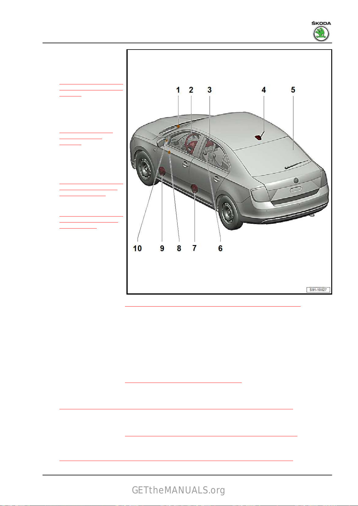
1 - Aerial for GPS signal recep‐
GETtheMANUALS.org
tion
❑
Spaceback type only
❑ Removing and installing
⇒ “4.3 Removing and in‐
stalling the GPS aerial”,
page 87
2 - Multi-functional steering
wheel
❑
Description, removing
and installing
⇒ “6 Multi-functional
steering wheel”,
page 94
3 - Navigation system
❑
installed in the centre
console
❑ Removing and installing
⇒ “2.5 Removing and in‐
stalling the navigation
system”, page 68
❑ Plug
4 - Roof aerial
❑
♦ GPS - not valid for the
Spaceback type
♦ AM/FM and DAB
♦ GSM - equipment with ERA
Glonass (Russia, Belarus)
❑ with aerial amplifier
❑ Removing and installing
5 - Rear window aerial - R130-
❑
❑ Spaceback type with panoramic roof also has:
♦ a panoramic roof aerial - AM/FM receiver
♦ a side window aerial rear left - DAB receiver
❑ Removing and installing ⇒ Body Work; Rep. gr. 64
6 - Multimedia socket MEDIA-IN (USB, AUX-IN)
– Removing and installing
connections on the
navigation system
⇒ “2.6 Plug connections
on the navigation sys‐
tem”, page 69
for the receiver:
⇒ “4 Replacing aerials, aerial modules and aerial cables”, page 82
FM2 reception
⇒ “7 Multimedia socket MEDIA-IN”, page 96
Rapid NH 2013 ➤ , Rapid NH 2014 ➤
Electrical system - Edition 02.2018
7 - Rear full-range speaker
❑
Removing and installing
⇒ “8.1 Removing and installing front bass speaker and rear full-range speaker”, page 99
8 - Front treble speaker
❑
Vehicles with manual adjustment of exterior mirrors
❑ Removing and installing
9 - Front bass speaker
❑
Removing and installing
⇒ “8.1 Removing and installing front bass speaker and rear full-range speaker”, page 99
⇒ “8.2 Removing and installing the front treble speaker”, page 99
2. Amundsen+ navigation system - installed up to CW 21.2015 67
Page 76

Rapid NH 2013 ➤ , Rapid NH 2014 ➤
GETtheMANUALS.org
Electrical system - Edition 02.2018
10 - Front treble speaker
❑
Vehicles with electrically adjustable exterior mirrors
❑ Removing and installing
⇒ “8.2 Removing and installing the front treble speaker”, page 99
2.5 Removing and installing the navigation system
Note
The part number for the complete navigation system is indicated
on a sticker on the housing of the navigation system.
Removing
– Switch off the radio, all electrical components and take out the
ignition key.
– Carefully unlock the cover frame -1- of the navigation menu
with the removal wedge - 3409- .
– Unscrew screws -arrows-.
– Pull the navigation system out of the dash panel.
– Compress plug catch -arrows-.
68 Rep. gr.91 - Radio, telephone, navigation
Page 77

Rapid NH 2013 ➤ , Rapid NH 2014 ➤
GETtheMANUALS.org
– Open catch clamp -arrow- and disconnect plug.
– Release plug of antenna socket -arrows- and disconnect.
Installing
Installation is performed in the reverse order, pay attention to the
following points:
Note
When inserting into the dash panel on no account press on the
display or on the buttons otherwise the navigation system may be
damaged.
Electrical system - Edition 02.2018
If the navigation system was replaced:
– Enter the safety code
⇒ “2.3 Electronic anti-theft coding”, page 65 and code the nav‐
igation ⇒ Vehicle diagnostic tester.
Tightening torques
Fixing screws for navigation system 1.5 Nm
2.6 Plug
connections on the navigation sys‐
tem
The current pin assignment can be found in ⇒ Current flow dia‐
grams,
type and model year.
Electrical fault finding and Fitting locations, depending on
2.7 Aerial for GPS signal reception
Removing and installing
⇒ “4 Replacing aerials, aerial modules and aerial cables”,
page 82 .
2.8 Diagnosis of the navigation system
Carry out diagnosis with the ⇒ Vehicle diagnostic tester in the
function “Targeted Fault Finding”.
2. Amundsen+ navigation system - installed up to CW 21.2015 69
Page 78

Rapid NH 2013 ➤ , Rapid NH 2014 ➤
GETtheMANUALS.org
Electrical system - Edition 02.2018
3 Infotainment system - installed as of
CW 22.2015
⇒ “3.1 Infotainment system - general notes”, page 70
⇒ “3.2 Summary of components - Infotainment system”,
page 70
⇒ “3.3 Installation – Infotainment system”, page 72
⇒ “3.4 Removing and installing the Infotainment display/control
unit”, page 74
⇒ “3.5 Remove and install infotainment display unit”, page 77
⇒ “3.6 Removing and installing the infotainment control unit”,
page 78
⇒ “3.7 Electronic anti-theft coding”, page 79
⇒ “3.8 Basic (Blues) infotainment - initial setup, self-diagnosis”,
page 80
3.1 Infotainment system - general notes
Infotainment system - installed as of model year 2016 (as of CW
22.2015)
♦ Infotainment system = Multimedia information system (MIB –
modular infotainment kit).
♦ It enables the driver to access the vehicle setting, assistance
systems and comfort functions via a single system.
Further information and description of function:
⇒ Operating instructions Rapid
⇒ Owner's manual – Infotainment
3.2 Summary of components - Infotainment
system
Note
The number and the design of the components depend on the
vehicle equipment and on the model year.
70 Rep. gr.91 - Radio, telephone, navigation
Page 79

Rapid NH 2013 ➤ , Rapid NH 2014 ➤
GETtheMANUALS.org
Electrical system - Edition 02.2018
1 - Aerial for GPS signal recep‐
tion
On
vehicles for Russia and Be‐
larus with the ERA Glonass
system and on vehicles with‐
out DAB (digital radio receiv‐
er), the GPS aerial is on the
roof (does not apply to the
Spaceback model with panor‐
amic sunroof)
❑ Removing and installing
⇒ “4.2 Removing and in‐
stalling roof aerial”,
page 85
On
other vehicles, the aerial is
under the dash panel (does not
apply to vehicles for Russia
with heated windscreen)
❑ Removing and installing
⇒ “4.3 Removing and in‐
stalling the GPS aerial”,
page 87
2 - Multi-functional steering
wheel
❑
Description, removing
and installing
⇒ “6 Multi-functional
steering wheel”,
page 94
3 - Infotainment display unit
(Bolero, Amundsen)/display
and
control unit (Blues, Swing)
❑ Removing and installing
(Blues, Swing equip‐
ment)
⇒ “3.4 Removing and in‐
stalling the Infotainment display/control unit”, page 74
❑
Removing and installing (Bolero, Amundsen equipment)
⇒ “3.5 Remove and install infotainment display unit”, page 77
4 - Infotainment control unit
❑
Bolero, Amundsen equipment
❑ Removing and installing
5 - Roof aerial
❑
Depending on equipment and country version – AM/FM, DAB, GSM, GPS reception
❑ with aerial amplifier
❑ Removing and installing
6 - Rear window aerial - R130-
❑
FM2 reception
❑ Spaceback type with panoramic roof also has:
♦ a panoramic roof aerial - AM/FM receiver
♦ a side window aerial rear left - DAB receiver
❑ Removing and installing ⇒ Body Work; Rep. gr. 64
7 - Connection for external audio sources AUX-IN - R199-
❑ is independently located in the centre console next to the handbrake
⇒ “3.6 Removing and installing the infotainment control unit”, page 78
⇒ “4 Replacing aerials, aerial modules and aerial cables”, page 82
3. Infotainment system - installed as of CW 22.2015 71
Page 80

Rapid NH 2013 ➤ , Rapid NH 2014 ➤
GETtheMANUALS.org
Electrical system - Edition 02.2018
– Removing and installing
⇒ “7.3 Removing and installing connection for external audio sources R199 (AUX-IN, USB) ”,
page 97
8 - Multimedia socket MEDIA-IN (USB, AUX-IN)
–
Removing and installing
9 - Rear full-range speaker
❑
Removing and installing
⇒ “8.1 Removing and installing front bass speaker and rear full-range speaker”, page 99
10 - Front treble speaker
❑
Vehicles with manual adjustment of exterior mirrors
❑ Removing and installing
11 - Front bass speaker
❑
Removing and installing
⇒ “8.1 Removing and installing front bass speaker and rear full-range speaker”, page 99
12 - Front treble speaker
❑
Vehicles with electrically adjustable exterior mirrors
❑ Removing and installing
⇒ “7 Multimedia socket MEDIA-IN”, page 96
⇒ “8.2 Removing and installing the front treble speaker”, page 99
⇒ “8.2 Removing and installing the front treble speaker”, page 99
3.3 Installation – Infotainment system
⇒ “3.3.1 Basic infotainment equipment BASIC ”, page 72
⇒ “3.3.2 Mid-range infotainment equipment ENTRY ”, page 73
⇒ “3.3.3 Maximum infotainment equipment STANDARD ”,
page 74
3.3.1 Basic infotainment equipment “BASIC”
“Blues” installation
Basic type:
♦ round display
♦ Radio RDS AM/FM
♦ SD card slot
♦ External media inputs – sockets AUX-IN, USB
♦ Passive CAN bus – without component protection
♦ 4 x 20 W
Optional extension:
♦ Control option via the multifunction steering wheel
Removing and installing
⇒ “3.4 Removing and installing the Infotainment display/control
unit”, page 74
⇒ “3.8 Basic (Blues) infotainment - initial setup, self-diagnosis”,
page 80
72 Rep. gr.91 - Radio, telephone, navigation
Page 81

Rapid NH 2013 ➤ , Rapid NH 2014 ➤
GETtheMANUALS.org
3.3.2 Mid-range infotainment equipment “EN‐
TRY”
Set “Swing”
Display and control unit form a single unit
Basic type:
♦ 5" colour touchscreen
♦ Radio RDS AM/FM
♦ SD card slot
♦ External media inputs – sockets AUX-IN, USB
♦ Vehicle comfort functions displays and settings
♦ Phone service
♦ i-Pod
Optional extension:
♦ Control option via the multifunction steering wheel
♦ DAB (digital reception – Entry Plus)
♦ Bluetooth
♦ Škoda Surround
Removing and installing
⇒ “3.4 Removing and installing the Infotainment display/control
unit”, page 74
⇒ “3.7 Electronic anti-theft coding”, page 79
Electrical system - Edition 02.2018
3. Infotainment system - installed as of CW 22.2015 73
Page 82

Rapid NH 2013 ➤ , Rapid NH 2014 ➤
GETtheMANUALS.org
Electrical system - Edition 02.2018
3.3.3 Maximum infotainment equipment “STANDARD”
Bolero, Amundsen installation
1 - Infotainment display unit
2 - Infotainment control unit
Basic type:
♦ 6.5" capacitive touchscreen
♦ Radio RDS AM/FM
♦ SD card slot
♦ External media inputs – sockets AUX-IN, USB
♦ Vehicle comfort functions displays and settings
♦ Bluetooth
♦ Telephone + text message display
♦ i-Pod
♦ Mirror link
Optional extension:
♦ Control option via the multifunction steering wheel
♦ DAB (digital receiver)
♦ Škoda Surround
Amundsen
Functions such as Bolero, plus:
♦ 2 x SD card slot
♦ Navigation with 2D and 2.5D display (bird's eye view)
Removing and installing infotainment:
♦ Display units
⇒ “3.5 Remove and install infotainment display unit”,
page 77
♦ Control units
⇒ “3.6 Removing and installing the infotainment control unit”,
page 78
⇒ “3.7 Electronic anti-theft coding”, page 79
3.4 Removing and installing the Infotain‐
ment display/control unit
♦ Basic infotainment set (Blues) and Entry set (Swing)
Note
Before removing, take out any data media in the unit ⇒ Infotain‐
ment Operating Instructions .
Removing
– Switch off infotainment and all electrical components and re‐
move the ignition key.
74 Rep. gr.91 - Radio, telephone, navigation
Page 83

Caution
GETtheMANUALS.org
When using the lever tool, mask points where the lever tool is
applied using commercially available adhesive tape.
– Carefully prise off top cover for infotainment -1- with the re‐
moval wedge - 3409- (start from bottom edge of the cover.
Blues:
Swing:
Rapid NH 2013 ➤ , Rapid NH 2014 ➤
Electrical system - Edition 02.2018
– Unscrew
unit out of the dash panel.
Blues:
Swing up to CW 21/2017:
the screws -arrows- and pull the infotainment control
3. Infotainment system - installed as of CW 22.2015 75
Page 84

Rapid NH 2013 ➤ , Rapid NH 2014 ➤
GETtheMANUALS.org
Electrical system - Edition 02.2018
Spring as of CW 22.2017:
– Insert unlocking tools into the openings in the display unit
-see fig.- until there is an audible click.
– Pull on the release tools -arrows- to remove the display unit
-1-.
All radios:
– Compress plug catch -arrows-.
– Open catch clamp -arrow- and disconnect plug.
– Blues infotainment - unlock plug of antenna socket -arrow- and
disconnect.
76 Rep. gr.91 - Radio, telephone, navigation
Page 85

Rapid NH 2013 ➤ , Rapid NH 2014 ➤
GETtheMANUALS.org
– Swing infotainment - unlock plug of antenna sockets
-arrows- and disconnect.
Installing
Installation is performed in the reverse order, pay attention to the
following points:
Note
When pushing the navigation system in, do not under any cir‐
cumstances press on the display or buttons. This may damage
the unit.
– If the infotainment control unit has been replaced, perform in‐
itial setup.
♦ Swing infotainment control unit
⇒ “3.7 Electronic anti-theft coding”, page 79
♦ Blues infotainment control unit
⇒ “3.8 Basic (Blues) infotainment - initial setup, self-diagno‐
sis”, page 80
Tightening torques
Electrical system - Edition 02.2018
Fixing screw for infotainment control unit 1.5 Nm
3.5 Remove
and install infotainment display
unit
♦ Standard infotainment set (Bolero and Amundsen)
Removing
– Switch off infotainment and all electrical components and re‐
move the ignition key.
Caution
When using the lever tool, mask points where the lever tool is
applied using commercially available adhesive tape.
– Carefully prise off top cover for infotainment -1- with the re‐
moval wedge - 3409- (start from bottom edge of the cover.
3. Infotainment system - installed as of CW 22.2015 77
Page 86

Rapid NH 2013 ➤ , Rapid NH 2014 ➤
GETtheMANUALS.org
Electrical system - Edition 02.2018
– Unscrew screws -arrows-.
– Remove the display unit from the dash panel.
– Release connector and pull it off.
Installing
Installation is performed in the reverse order, pay attention to the
following points:
Note
When inserting into the dash panel, do not press on the display
or on the operating button, otherwise the display unit may be
damaged.
When replacing, connect the ⇒ Vehicle diagnostic tester, retrieve
the fault memory and delete if necessary.
Tightening torques
Fixing screws for display unit
1.5 Nm
3.6 Removing and installing the infotain‐
ment control unit
Special tools and workshop equipment required
♦ Extractor - T10057Removing
– Remove
control unit ⇒ Infotainment operating manual .
– Switch off the ignition and all electrical consumers!
– Remove the storage tray from the dash panel on the front
passenger side and let it hang there considering the connec‐
ted cable lengths ⇒ Body Work - Assembly work; Rep. gr.
70 .
– Compress plug catch -arrows-.
the data storage device that is still in the Infotainment
78 Rep. gr.91 - Radio, telephone, navigation
Page 87

– Open catch clamp -arrow- and disconnect plug.
GETtheMANUALS.org
– Release and pull off other plug connections.
– Unscrew bolts -3-.
– Remove bracket -4- with unit -2- from the storage tray -1-.
Rapid NH 2013 ➤ , Rapid NH 2014 ➤
Electrical system - Edition 02.2018
– Insert the release tools - T10057- into the bores of the unit,
until they click audibly into place.
– Remove unit -1- from the bracket by pulling on the release
tools arrows -arrows-.
– Loosen
them from unit.
Installing
Installation is performed in the reverse order, pay attention to the
following points:
When replacing, couple the Infotainment control unit (see
⇒ “3.7 Electronic anti-theft coding”, page 79 ).
Tightening torques
Tighten the screws -3- for attaching the
infotainment control unit
the release tools by pressing on the clips and remove
1.5 Nm
3.7 Electronic anti-theft coding
Note
The following does not apply to the “Basic” (Blues) infotainment
equipment.
3. Infotainment system - installed as of CW 22.2015 79
Page 88

Rapid NH 2013 ➤ , Rapid NH 2014 ➤
GETtheMANUALS.org
Electrical system - Edition 02.2018
The Infotainment display/control unit is equipped with an elec‐
tronic comfort anti-theft coding, which operates in combination
with the dash panel insert.
The Infotainment display/control unit must be coupled with an ap‐
propriate vehicle using the ⇒ Vehicle diagnostic tester. The se‐
curity code is no longer entered.
The Infotainment display/control unit, which is installed at the fac‐
tory, is coupled only when it is used for the first time with the
corresponding
connected or if the Infotainment display/control unit is removed
from a vehicle and then re-installed in the same vehicle, coupling
with the corresponding vehicle is no longer valid.
If the dash panel insert is replaced, the Infotainment display/con‐
trol unit must be coupled with the relevant vehicle once again.
The user must have a valid authorisation to use a programme for
coupling the Infotainment display/control unit.
Additional information ⇒ Infotainment operating manual .
vehicle. If the battery is disconnected and then re‐
3.8 “Basic” (Blues) infotainment - initial set‐
up, self-diagnosis
Valid for Blues radio installed as of CW 22.2015.
1. Commissioning
Phase 1A:
– If the unit is in transport mode (it has never been switched on),
press the button to switch the unit on (on/off).
Result of phase 1A:
The unit switches to “select number of speakers” mode (2-4
speakers).
Phase 1B:
– If the unit has already been switched on, press the button to
switch on the unit (on/off) and then briefly press the RADIO
SETUP and EXTRAS buttons simultaneously.
,
Result of phase 1B:
The unit switches to “select number of speakers” mode (2-4
speakers).
Phase 2:
– To select the number of speakers installed in the vehicle, press
the ◄ button (only front speakers, x2 bass + x2 treble loud‐
speakers) or the ► button (x2 bass at front + x2 treble loud‐
speaker and x2 wide band loudspeakers at rear).
Note
The number of installs loudspeakers can be determined from the
vehicle identification number (VIN code) in the ELSA vehicle data.
Result of phase 2:
“Diagnosis OK” or “Not OK” is displayed on the unit's display.
Diagnosis OK:
Activation has been successful and the unit can be operated by
pressing the ►
station
tuning, see ⇒ BASIC infotainment operating instructions .
button or after a time limit (approx. 10 sec) for
80 Rep. gr.91 - Radio, telephone, navigation
Page 89

Rapid NH 2013 ➤ , Rapid NH 2014 ➤
GETtheMANUALS.org
Not OK:
To be operated, all the system components must be connected
to the unit.
If the unit identifies that one of the components listed below is not
connected,
the unit has not recognised is shown on the display (max. eight
components, depending on equipment):
LF - Front left speaker
RF - Front right speaker
LR - Rear left speaker
RR - Rear right speaker
A1 - Primary aerial
A2 - Secondary aerial
USB - USB connection
AUX - Connection for external audio sources (AUX)
The unit is then switched off by pressing the ►
period of time (approx. 10 sec).
Once the indicated components have been connected, repeat the
procedure from phase 1B.
2. Service mode
For information only:
Phase 1:
– Press the button to turn on the unit (on/off).
Phase 2:
– Press the SETUP button for approximately 5 seconds.
“Not OK” and the abbreviation for the component that
button or after a
Electrical system - Edition 02.2018
In service mode, you can navigate by using the ◄ and ► buttons
to view three items of information.
Part NO - Number of the unit
HW - Hardware
SW - Software
3. Infotainment system - installed as of CW 22.2015 81
Page 90

Rapid NH 2013 ➤ , Rapid NH 2014 ➤
GETtheMANUALS.org
Electrical system - Edition 02.2018
4 Replacing aerials, aerial modules
and aerial cables
⇒ “4.1 Summary of components, Rapid”, page 82
⇒ “4.2 Removing and installing roof aerial”, page 85
⇒ “4.3 Removing and installing the GPS aerial”, page 87
⇒ “4.4 Removing and installing the GSM aerial”, page 88
⇒ “4.5 Rear or side window aerial (Spaceback)”, page 89
⇒ “4.6 Panoramic roof aerial”, page 89
⇒ “4.7 Aerial module R254 for rear window aerial”, page 89
⇒ “4.8 Aerial module for rear left side window aerial”, page 90
⇒ “4.9 Aerial module for panoramic roof aerial”, page 90
⇒ “4.10 Replacing aerial cables”, page 91
4.1 Summary of components, Rapid
⇒ “4.1.1 Summary of components - antennas, Rapid”,
page 82
⇒ “4.1.2 Overview of components - Antennas, Spaceback”, page
84
4.1.1 Summary of components - antennas, Rapid
82 Rep. gr.91 - Radio, telephone, navigation
Page 91

1 - GPS aerial - R50-
GETtheMANUALS.org
On
vehicles for Russia and Be‐
larus with the ERA Glonass
system and on vehicles with‐
out DAB (digital radio receiv‐
er), the GPS aerial is on the
roof
On other vehicles, the aerial is
under the dash panel (does not
apply to vehicles for Russia
with heated windscreen)
❑ Removing and installing
⇒ “4.3 Removing and in‐
stalling the GPS aerial”,
page 87
2 - Rear window antenna 1 R130-
❑
FM2 reception
❑ Removing and installing
⇒ Body Work; Rep. gr.
64
3 - Roof aerial - R216-
❑ Depending on equip‐
ment and country ver‐
sion – AM/FM, DAB,
GSM, GPS reception
❑ with aerial amplifier
❑ Removing and installing
⇒ “4.2 Removing and in‐
stalling roof aerial”,
page 85
4 - Aerial module - R254- for
rear window aerial
❑ Removing
⇒ “4.7 Aerial module
R254 for rear window aerial”, page 89
and installing
Rapid NH 2013 ➤ , Rapid NH 2014 ➤
Electrical system - Edition 02.2018
4. Replacing aerials, aerial modules and aerial cables 83
Page 92

Rapid NH 2013 ➤ , Rapid NH 2014 ➤
GETtheMANUALS.org
Electrical system - Edition 02.2018
4.1.2 Overview of components - Antennas, Spaceback
1 - GPS aerial - R50On
vehicles for Russia and Be‐
larus with the ERA Glonass
system and on vehicles with‐
out DAB (digital radio receiv‐
er), the GPS aerial is on the
roof (does not apply to vehicles
with panoramic sunroof)
On other vehicles, the aerial is
under the dash panel (does not
apply to vehicles for Russia
with heated windscreen)
❑ Removing and installing
⇒ “4.3 Removing and in‐
stalling the GPS aerial”,
page 87
2 - Antenna module - R11- in‐
tegrated in the panoramic roof
❑
Applies to vehicles with
a panoramic roof
❑ Removing and installing
⇒ Body Work; Rep. gr.
64
3 - Antenna module - R108- for
panoramic roof aerial
❑ Removing and installing
⇒ “4.9 Aerial module for
panoramic roof aerial”,
page 90
4 - Roof aerial - R216-
❑
Depending on equip‐
ment and country ver‐
sion – AM/FM, DAB,
GSM, GPS reception
❑ with aerial amplifier
❑ Removing and installing
5 - Aerial module - R254- for rear window aerial
❑
Removing and installing
6 - Rear window antenna 1 - R130-
❑
FM2 reception
❑ Removing and installing ⇒ Body Work; Rep. gr. 64
7 - Digital radio antenna - R183-
❑ in the left side window
8 - Left aerial module - R108-
❑ Removing and installing
⇒ “4.2 Removing and installing roof aerial”, page 85
⇒ “4.7 Aerial module R254 for rear window aerial”, page 89
⇒ “4.8 Aerial module for rear left side window aerial”, page 90
84 Rep. gr.91 - Radio, telephone, navigation
Page 93

Rapid NH 2013 ➤ , Rapid NH 2014 ➤
GETtheMANUALS.org
Electrical system - Edition 02.2018
4.2 Removing and installing roof aerial
⇒ “4.2.1 Removing and installing the roof aerial for radio up to CW
21.2015”, page 85
⇒ “4.2.2 Removing and installing the roof aerial for radio and nav‐
igation up to CW 21.2015”, page 86
⇒ “4.2.3 Removing and installing the roof aerial as of CW
22.2015”, page 87
4.2.1 Removing and installing the roof aerial for radio up to CW 21.2015
Note
Before installing the radio aerial, switch off all electrical consumers and take out the ignition key.
1 - Aerial rod
2 - Aerial base with integrated
amplifier
❑ to remove and install:
♦ Detach the moulded head‐
liner up to the A-pillars and
carefully unhook the rear
section downwards. For ve‐
hicles with panoramic sun‐
roof, lower the moulded
headliner completely ⇒
Body Work; Rep. gr. 70 .
3 - Connection for the antenna
cable going to the radio
4 - Hexagon nut with serrated
washer
❑ 6 Nm
❑ hexagonal nut is con‐
nected to serrated
washer by a plastic ring
❑ apply contact grease on
the inside of roof in the
area of the serrated
washer
5 - Roof
4. Replacing aerials, aerial modules and aerial cables 85
Page 94

Rapid NH 2013 ➤ , Rapid NH 2014 ➤
GETtheMANUALS.org
Electrical system - Edition 02.2018
4.2.2 Removing and installing the roof aerial
for radio and navigation up to CW
21.2015
Note
♦
The number of connections of the aerial base depends on the
vehicle equipment.
♦
Before installing the radio aerial, switch off all electrical con‐
sumers and take out the ignition key.
1 - Aerial rod
❑ can be removed
2 - Aerial base with integrated
amplifier
❑ to remove and install:
♦ Detach the moulded head‐
liner up to the A-pillars and
carefully unhook the rear
section downwards. For ve‐
hicles with panoramic sun‐
roof, lower the moulded
headliner completely ⇒
Body Work; Rep. gr. 70 .
3 - Hexagon nut with serrated
washer
❑ 6 Nm
❑ hexagonal nut is con‐
nected to serrated
washer by a plastic ring
❑ apply contact grease on
the inside of roof in the
area of the serrated
washer
4 - Aerial cable to radio
❑ White plug
5 - Aerial cable to telephone
❑ Lilac plug
❑ not assigned
6 - Aerial cable to navigation
❑ Blue plug
7 - Aerial cable to radio
❑ black plug
❑ Reception of digital programme
86 Rep. gr.91 - Radio, telephone, navigation
Page 95

Rapid NH 2013 ➤ , Rapid NH 2014 ➤
GETtheMANUALS.org
4.2.3 Removing and installing the roof aerial as of CW 22.2015
Note
♦
The number of connections of the aerial base depends on the
vehicle equipment.
♦
Before installing the radio aerial, switch off all electrical con‐
sumers and take out the ignition key.
Removing
– Detach the moulded headliner up to the A-pillars and carefully
unhook the rear section downwards. For vehicles with panor‐
amic sunroof, lower the moulded headliner completely ⇒ Body
Work; Rep. gr. 70 .
– Release and pull off the connector -1- on the aerial cables.
– Unscrew bolt -3-.
– Open holding clamp -2- and remove the aerial.
Installing
– Put aerial in position and press down the holding clamp -2-
until it clicks into place.
– Tighten fixing screw.
– Further installation occurs in reverse order.
Tightening torques
Electrical system - Edition 02.2018
Fixing screw for aerial, Pos. -3-
6 Nm
4.3 Removing and installing the GPS aerial
Note
♦
Apples to the Spaceback model and all vehicles equipped with
navigation system from CW 22/2015, except vehicles with the
ERA Glonass system (Russia and Belarus – GPS aerial on the
roof, except the Spaceback model with panoramic sunroof).
♦
The GPS aerial is located on the dash panel cross member
behind the dash panel insert.
Removing
– Removing the dash panel ⇒ Body Work; Rep. gr. 70 .
Version 1:
– Push aerial -1- from underneath off the mount on the dash
panel cross member -arrow-.
4. Replacing aerials, aerial modules and aerial cables 87
Page 96

Rapid NH 2013 ➤ , Rapid NH 2014 ➤
GETtheMANUALS.org
Electrical system - Edition 02.2018
– When pressing out the aerial, press the retaining tabs
-arrows-.
– Unlock and remove the aerial connection.
Version 2:
– Release
the retaining tab -arrows-.
and remove the GPS aerial -2- with bracket -1- out of
– Release
-B- and take out of the bracket -2-.
– Unlock and remove the aerial connection.
Installing
Installation is performed in the reverse order, pay attention to the
following points:
– The aerial lug/bracket, see illustration, locks the correct posi‐
tion.
4.4 Removing
Applies to the Spaceback model; on the Sedan model, the GSM
aerial is on the roof.
The GSM aerial is located on the bracket of the control unit for
emergency call module and communication unit - J949- behind
the dash panel on the driver's side.
– Switch off the ignition and all electrical consumers!
– Place the ignition key outside the vehicle to avoid accidentally
turning on the ignition.
– Remove the side vent from the dash panel on the driver's side
⇒ Heating, Air Conditioning; Rep. gr. 80 .
GPS aerial -1- from the retaining tabs, arrows -A- and
and installing the GSM aerial
Note
88 Rep. gr.91 - Radio, telephone, navigation
Page 97

– Remove the side cover on the dash panel -1- on the driver's
GETtheMANUALS.org
side in -direction of arrow-
– Remove the light switch
⇒ “2.1 Removing and installing light switch”, page 207
headlight range control adjuster
⇒ “2.2 Removing and installing the headlight range control ad‐
juster”, page 207 .
– Push off the retaining tab in direction of arrow -A- and then
slide the aerial
-B-.
– Unlock and remove the aerial connection.
Installing
Installation is carried out in the reverse order.
-1- out of the bracket -2- in direction of arrow
.
and the
Rapid NH 2013 ➤ , Rapid NH 2014 ➤
Electrical system - Edition 02.2018
4.5 Rear
The aerial cannot be replaced separately, in the event of a fault,
the rear- side window must be replaced ⇒ Body Work; Rep. gr.
64 .
There are frequency filters for the frequency modulation on the
supply
parts of the wiring harness and can not be replaced separately.
cables for the rear window heating, which are component
or side window aerial (Spaceback)
4.6 Panoramic roof aerial
The aerial cannot be replaced separately, in the event of a fault,
the panoramic roof must be replaced ⇒ Body Work; Rep. gr. 64 .
4.7 Aerial module - R254- for rear window
aerial
Located next to the rear window wiper motor.
Removing
– Remove the cover for the rear wiper motor.
4. Replacing aerials, aerial modules and aerial cables 89
Page 98

Rapid NH 2013 ➤ , Rapid NH 2014 ➤
GETtheMANUALS.org
Electrical system - Edition 02.2018
– Unlock and disconnect connectors -1- and -2-.
– Unscrew the screw -3-, but not fully.
– Undo
Installing
Installation is performed in the reverse order, pay attention to the
following points:
Tightening torques
screw with clip -3- out of the bearing, move aerial module
-4- -arrow- and remove.
Fixing screw for aerial module, Pos. -3-
2 Nm
4.8 Aerial module for rear left side window aerial
For Spaceback type only.
Removing
– Switch off the ignition and all electrical consumers!
– Remove
– Unlock and disconnect connectors -1- and -3-.
– Unscrew the screw -4-, but not fully.
– Remove the screw and clip -4- from the mounting in direction
of arrow -A-; slide out and remove the aerial module -2- in
direction of arrow -B-.
Installing
Installation is performed in the reverse order, pay attention to the
following points:
Tightening torques
Fixing screw for aerial module, Pos. -4-
top left C pillar trim panel ⇒ Body Work; Rep. gr. 70 .
2 Nm
4.9 Aerial module for panoramic roof aerial
The aerial is located underneath the rear left headlining.
Removing
– Switch off the ignition and all electrical consumers!
– Unhook headlining ⇒ Body Work; Rep. gr. 70 .
– Unlock and disconnect connectors -3- and -4-.
– Unscrew the screw -2-, but not fully.
– Remove the screw and clip -2- from the mounting in direction
of arrow -A-; slide out and remove the aerial module
direction of arrow -B-.
Installing
Installation is performed in the reverse order, pay attention to the
following points:
Tightening torques
Fixing screw for aerial module, Pos. -2-
-1- in
2 Nm
90 Rep. gr.91 - Radio, telephone, navigation
Page 99

4.10 Replacing aerial cables
GETtheMANUALS.org
Note
♦
Aerial cables cannot be repaired Replace damaged aerial ca‐
bles with a new original part, see ⇒ Electronic Catalogue of
Original Parts“ETKA” ; Accessories; sub-group 35.
♦
Do not crimp aerial cable or bend excessively! The minimum
bending radius must not be less than 50 mm.
– Cut off aerial connection from the defective cable.
The remainder of the defective cable remains in the vehicle.
– Lay new aerial cable close to the original cable and attach.
– Perform a functional test.
Rapid NH 2013 ➤ , Rapid NH 2014 ➤
Electrical system - Edition 02.2018
4. Replacing aerials, aerial modules and aerial cables 91
Page 100

Rapid NH 2013 ➤ , Rapid NH 2014 ➤
GETtheMANUALS.org
Electrical system - Edition 02.2018
5 Telephone system
⇒ “5.1 Mobile phone pre-installation”, page 92
⇒ “5.2 Removing and installing the control unit for the mobile
phone operating electronics J412 ”, page 92
⇒ “5.3 Removing and installing the microphone for the telephone
R38 ”, page 93
5.1 Mobile phone pre-installation
Further information and description of function:
♦ ⇒ Operating instructions Rapid
♦ ⇒ Self-study programme No. 81 ; Bluetooth in Škoda vehicles
Mobile phone pre-installation (universal)
Valid for vehicles manufactured up to CW 21.2015
1 - Radio
2 - Door speakers
3 - Voltage supply for telephone system
4 - Microphone for the telephone - R38- , in the interior light
5 - 54-pin connector on the control unit for the mobile phone
operating electronics - J412- (transmission/receiver unit)
6 - Control unit for mobile phone operating electronics - J412-
(transmission/receiver unit)
Mobile phone pre-installation (universal) on vehicles with the
Amundsen+ navigation system and vehicles with mobile phone
pre-installation manufactured as of CW 22.2015
Note
A Bluetooth module is integrated in the navigation system Amund‐
sen+ which fulfils the function of the GSM II mobile phone preinstallation (the control unit for the mobile phone operating
electronics - J412- that is located under the right front seat is no
longer fitted)
1 - Navigation system/infotainment
2 - Door speakers
3 - Microphone for the telephone - R38- , in the interior light
5.2 Removing and installing the control unit
for
the mobile phone operating electron‐
ics - J412-
Installed up to CW 21.2015. As of CW 22.2015, mobile phone preinstallation is integrated into the infotainment control unit (see
⇒ “3.3 Installation – Infotainment system”, page 72 ).
The control unit is located below the right front seat under the floor
covering.
Removing
– Switch off the ignition and all electrical consumers!
– Remove front passenger seat ⇒ Body Work; Rep. gr. 72 .
92 Rep. gr.91 - Radio, telephone, navigation
 Loading...