


31-5048
6.1ch Sirius-Ready A/V
Surround Receiver
Thank you for purchasing this Accurian 6.1 ch Sirius-Ready A/V Surround Receiver.
WHAT’s INCLUDED
|
AM Loop Antenna |
User’s Guide |
|
FM T-Type Antenna |
Adapter for FM Antenna |
|
Remote Control |
Batteries for Remote Control (2) |
Please read this user’s guide before installing, setting up, or using your new Receiver
CAUTION: TO REDUCE THE RISK OF ELECTRIC SHOCK, DO NOT REMOVE COVER (OR BACK). NO USER SERVICEABLE PARTS INSIDE. REFER SERVICING TO QUALIFIED SERVICE PERSONNEL.
This symbol is intended to alert the user to the presence of uninsulated dangerous voltage within the product’s enclosure that may be of sufficient magnitude to constitute a risk of electric shock.
This symbol is intended to alert the user to the presence of important operating and maintenance (servicing) instructions in the literature accompanying this device.
WARNING:TO PREVENT FIRE OR SHOCK HAZARD, DO NOT EXPOSE THIS APPLIANCE TO RAIN OR MOISTURE.
The equipment draws nominal nonoperating power from the AC outlet with its POWER switch in the STANDBY position.
For CANADA
CAUTION - TO PREVENT ELECTRIC SHOCK, MATCH WIDE BLADE OF PLUG TO WIDE SLOT, FULLY INSERT.
CAUTION Regarding Placement
To maintain proper ventilation, be sure to leave a space around the unit (from the largest outer dimensions including projections) equal to, or greater than, shown below.
Left and Right Panels : 4 inches (10 cm)
Rear Panel : 4 inches (10 cm)
Top Panel : 20 inches (50 cm)
2

IMPORTANT SAFETY INSTRUCTIONS
1.Read Instructions — All the safety and operating instructions should be read before the product is operated.
2.Retain Instructions — The safety and operating instructions should be retained for future reference.
3.Heed Warnings — All warnings on the product and in the operating instructions should be adhered to.
4.Follow Instructions — All operating and use instructions should be followed.
5.Cleaning — Unplug this product from the wall outlet before cleaning. Do not use liquid cleaners or aerosol cleaners. Use a damp cloth for cleaning.
6.Attachments — Do not use attachments not recommended by the product manufacturer as they may cause hazards.
7.Water and Moisture — Do not use this product near water – for example, near a bath tub, wash bowl, kitchen sink, or laundry tub; in a wet basement; or near a swimming pool; and the like.
8.Accessories — Do not place this product on an unstable cart, stand, tripod, bracket, or table.The product may fall, causing serious injury to a child or adult, and serious damage to the product. Use only with a cart, stand, tripod, bracket, or table recommended by the manufacturer, or sold with the product. Any mounting of the product should follow the manufacturer’s instructions, and should use a mounting accessory recommended by the manufacturer.
9.A product and cart combination should be moved with care. Quick stops, excessive force, and uneven surfaces may cause the product and cart combination to overturn.
10.Ventilation — Slots and openings in the cabinet are provided for ventilation and to ensure reliable operation of the product and to protect it from overheating, and these openings must not be blocked or covered.The openings should never be blocked by placing the product on a bed, sofa, rug, or other similar surface.
This product should not be placed in a built-in installation such as a bookcase or rack unless proper ventilation is provided or the manufacturer’s instructions have been adhered to.
11.Power Sources — This product should be operated only from the type of power source indicated on the marking label. If you are not sure of the type of power supply to your home, consult your product dealer or local power company. For products intended to operate from battery power, or other sources, refer to the operating instructions.
12.Grounding or Polarization — This product may be equipped with a polarized alternating-
3
current line plug (a plug having one blade wider than the other).This plug will fit into the power outlet only one way.This is a safety feature. If you are unable to insert the plug fully into the outlet, try reversing the plug. If the plug should still fail to fit, contact your electrician to replace your obsolete outlet. Do not defeat the safety purpose of the polarized plug.
13.Power-Cord Protection — Power-supply cords should be routed so that they are not likely to be walked on or pinched by items placed upon or against them, paying particular attention to cords at plugs, convenience receptacles, and the point where they exit from the product.
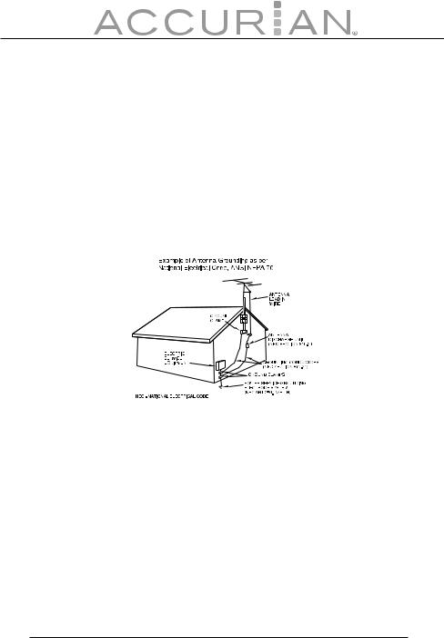
14.Outdoor Antenna Grounding — If an outside antenna or cable system is connected to the product, be sure the antenna or cable system is grounded so as to provide some protection against voltage surges and built-up static charges. Article 810 of the National Electrical Code, ANSI/NFPA 70, provides information with regard to proper grounding of the mast and supporting structure, grounding of the lead-in wire to an antenna discharge unit, size of grounding conductors, location of antenna-discharge unit, connection to grounding electrodes, and requirements for the grounding electrode.
NOTE TO CATV SYSTEM INSTALLER:
This reminder is provided to call the CATV (Cable TV) system installer’s attention to article 820-40 of the NEC that provides guidelines for proper grounding and, in particular, specifies that the cable ground shall be connected to the grounding system of the building, as close to the point of cable entry as possible.
15.Lightning — For added protection for this product during a lightning storm, or when it is left unattended and unused for long periods of time, unplug it from the wall outlet and disconnect the antenna or cable system.This will prevent damage to the product due to lightning and power-line surges.
16.Power Lines — An outside antenna system should not be located in the vicinity of overhead power lines or other electric light or power circuits, or where it can fall into such power lines or circuits.When installing an outside antenna system, extreme care should be taken to keep from touching such power lines or circuits as contact with them might be fatal.
17.Overloading — Do not overload wall outlets, extension cords, or integral convenience receptacles as this can result in risk of fire or electric shock.
4

18.Object and Liquid Entry — Never push objects of any kind into this product through openings as they may touch dangerous voltage points or short-out parts that could result in a fire or electric shock. Never spill liquid of any kind on the product.
19.Servicing — Do not attempt to service this product yourself as opening or removing covers may expose you to dangerous voltage or other hazards. Refer all servicing to qualified service personnel.
20.Damage Requiring Service — Unplug this product from the wall outlet and refer servicing to qualified service personnel under the following conditions:
a.When the power-supply cord or plug is damaged.
b.If liquid has been spilled, or objects have fallen into the product.
c.If the product has been exposed to rain or water.
d.If the product does not operate normally by following the operating instructions. Adjust only those controls that are covered by the operating instructions as an improper adjustment of other controls may result in damage and will often require extensive work by a qualified technician to restore the product to its normal operation.
e.If the product has been dropped or damaged in any way.
f.When the product exhibits a distinct change in performance — this indicates a need for service.
21.Replacement Parts — When replacement parts are required, be sure the service technician has used replacement parts specified by the manufacturer or have the same characteristics as the original part. Unauthorized substitutions may result in fire, electric shock, or other hazards.
22.Safety Check — Upon completion of any service or repairs to this product, ask the service technician to perform safety checks to determine that the product is in proper operating condition.
23.Wall or Ceiling Mounting — The product should be mounted to a wall or ceiling only as recommended by the manufacturer.
24.Heat — The product should be situated away from heat sources such as radiators, heat registers, stoves, or other products (including amplifiers) that produce heat.
5

Contents |
|
IMPORTANT SAFETY INSTRUCTIONS ................................... |
3 |
Introducing SIRIUS Satellite Radio ....................................... |
8 |
Getting Started |
9 |
Before Operating Your Product ............................................. |
9 |
Connecting Speakers .............................................................. |
10 |
Connecting Your Amplifier/Receiver |
11 |
Pre Out and Speakers............................................................... |
11 |
Choosing a Location for Your Speakers ............................ |
12 |
Audio Components .................................................................. |
15 |
Video Components .................................................................. |
17 |
Connecting Antennas.............................................................. |
19 |
Connecting the Sirius Home Tuner..................................... |
22 |
AC Power Cord............................................................................ |
23 |
Front Panel Controls |
24 |
Remote Control |
26 |
Remote Sensor ........................................................................... |
29 |
Battery Installation.................................................................... |
30 |
Advanced Operation |
31 |
Recording a Source................................................................... |
32 |
TONE Control ............................................................................. |
32 |
Muting .......................................................................................... |
32 |
Sleep Timer Function .............................................................. |
33 |
NIGHT MODE Function ........................................................... |
33 |
DIMMER ....................................................................................... |
33 |
Radio Reception |
34 |
FM MODE...................................................................................... |
35 |
Presetting |
36 |
Automatic Memory Presetting ............................................. |
36 |
Manual Memory Presetting .................................................. |
37 |
6

SIRIUS Satellite Radio Tuner |
37 |
Video Operations |
42 |
VCR Dubbing .............................................................................. |
42 |
Deck Dubbing ............................................................................ |
43 |
OSD Function.............................................................................. |
43 |
Speaker Configuration |
44 |
Size of Speakers ........................................................................ |
45 |
Balancing Speaker Relative Volume (Output Level) ..... |
47 |
Input the Distance From Your Listening Position ......... |
47 |
Balancing Speaker Relative Volume ................................... |
48 |
Surround Modes |
48 |
Selecting a Surround Mode .................................................. |
52 |
Setting up Surround Modes ................................................. |
52 |
Surround Mode and the Input Signal ................................ |
53 |
STEREO Mode ............................................................................ |
55 |
Troubleshooting |
56 |
Specifications |
58 |
7

Introducing SIRIUS Satellite Radio
With over 120 channels of the best entertainment and completely commercial-free music for your car, home or o ce. Only SIRIUS has more than 65 original music channels, from today’s hits to R&B oldies to classical masterpieces. From authentic country and real bluegrass to cool jazz, hot Latin, Reggae, rock and many more. Best of all, it’s all completely commercial-free.
SIRIUS also has more than 55 channels of world-class sports, news and entertainment. Included as part of your subscription, you get up to 16 NFL games a week, up to 40 NBA games a week and up to 40 NHL games a week, (Games are broadcast during their respective seasons.), coupled with great sports news from ESPN, the SIRIUS sports o ering is unrivaled. And don’t forget a host of other great news and entertainment, like NPR, CNBC, Fox News, Radio Disney and E! Entertainment Radio. For more information, visit www.sirius.com.
How to Subscribe
This unit is Sirius-ready. It requires a Sirius Connect™ Home Tuner (purchased separately) and a Sirius Satellite Radio subscription is needed to listen to the Sirius Satellite Radio. For more information, visit https://activate.siriusradio.com.
About the SIRIUS Mark
SIRIUS Satellite Radio Ready
© 2006 SIRIUS Satellite Radio Inc. "SIRIUS" and the SIRIUS dog logo are registered trademarks of SIRIUS Satellite Radio Inc.
8

Getting Started
Before Operating Your Product
•Choose your installation location carefully. Avoid placing it in direct sunlight or close to a source of heat. Also avoid locations subject to vibrations and excessive dust, heat, cold, or moisture.
•Do not cover the ventilation hole. Make sure there is enough space above and beside the amplifier/receiver. Do not place a CD player or other equipment on top of the amplifier/receiver.
•Do not open the cabinet as this might result in damage to the circuitry or electrical shock. If a foreign object should get into the set, contact your local RadioShack® store.
•When removing the power plug from the wall outlet, always pull directly on the plug, never yank the cord.
•Do not attempt to clean the unit with chemical solvents as this might damage the finish. Use a clean, dry cloth.
•Keep this manual in a safe place for future reference.
Caution
•Turn o the power of all the equipment before making connections.
•Read instructions of each component you intend to use with this unit.
•Be sure to insert each plug securely. To prevent hum and noise, do not bundle the connection cords with the power cord or speaker cord.
•Do not connect this unit and other components or to the main power until all connections between components have been completed.
9

Connecting Speakers
Caution: To avoid damaging the speakers with a sudden high-level signal, be sure to switch the power o before connecting the speakers.
•Check the impedance of your speakers.
•Connect speakers with an impedance of 6 ohms or more.
•The amplifier’s red speaker terminals are the positive (+) terminals and the black terminals are the negative (-) terminals.
•The + side of the speaker cable is marked to make it distinguishable from the - side of the cable. Connect this marked side to the red + terminal and the unmarked side to the black terminal.
•Prepare the speaker cords for connection by stripping o approximately 10 mm or less (no more, as this could cause a short circuit) of the outer insulation. Twist the wires tightly together so that they do not fray:
How to Connect
1.Loosen the knob by turning it counterclockwise.
2.Insert the bare part of the wire into the hole inside of each terminal.
3.Tighten the knob by turning it clockwise to secure the wire.
Note: Make sure the cord is fastened securely by pulling it lightly.
10
Connecting Your Amplifier/Receiver
Pre Out and Speakers
(OPTIONAL) |
|
|
POWERED |
FRONT |
|
SUBWOOFER |
||
|
CENTER |
LEFT |
|
RIGHT |
|
LEFT
RIGHT |
RIGHTHT |
LEFT |
SURROUND SURROUND
BACK
PRE OUT (SUB WOOFER) Jack
Use this jack to connect a powered sub woofer (power amplifier built in). If your sub woofer is a passive type (power amplifier is not built in), connect a monaural power amplifier to the PRE OUT jack and connect the sub woofer to the amplifier.
11
AC OUTLET
This outlet is only active when the receiver is turned on.
Caution: Make sure that the total power consumption of all equipment connected to the outlets on the receiver does not exceed 100 watts.
Choosing a Location for Your Speakers
Placing Your Speakers
|
Surround Left |
Subwoofer |
|
|
Front Left |
|
|
Front Center |
|
|
0 |
Surround |
|
|
Back |
|
45-60 |
|
|
|
|
|
Front Right |
110 |
Surround Right |
|
90 |
|
|
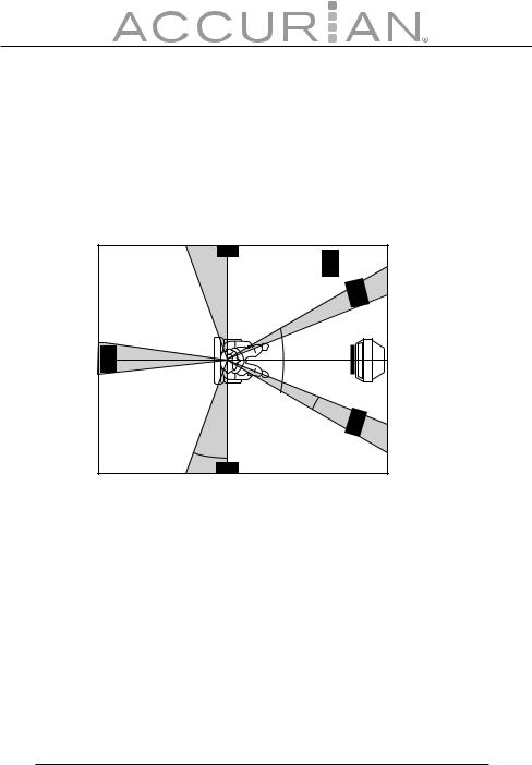
The ideal surround speaker system for this unit is 6.1 speaker system, using front left and right speakers, a center speaker, surround left and right speakers, a surround back speaker, and a subwoofer.
For best results we recommend that front speakers be of the same type, with identical or similar driver units. This will deliver smooth pans across the front sound stage as the action moves from side to side.
Your center channel speaker is very important as over 80% of the dialog from a typical motion picture emanates from the center channel. It should possess similar sonic characteristics to the main speakers. Surround channel speakers need not be identical to the front channel speakers, but they should be of high quality.
12

Bass e ects are an important part of home theater. For optimal enjoyment, a subwoofer should be used as it is optimized for low frequency reproduction. If you have full range front speakers, however, they may be used in place of a subwoofer with proper setting of the switches in the menu system.
Front Left and Right Speakers
We recommend to set the front L and R speakers with 45-60 degrees from the listening position.
Center Speaker
Align the front line of the center speaker with the front L/R speakers. Or place the center speaker a little backward from the line.
Surround Left and Right Speakers
When the receiver is used in surround operation, the preferred location for surround speakers is on the side walls of the room, at or slightly behind the listening position. The center of the speaker should face into the room.
Surround Back Speakers
Surround back speaker is required when a 6.1-channel system is installed. The speaker should be placed on a rear wall, behind the listening position. The center of the speaker should face into the room.
Subwoofer (Optional)
We recommend using a subwoofer to have maximum bass e ect. The subwoofer bears only low frequency range so you can place it anywhere in the room.
13
Height of the Speaker Units
Front Left and Right Speakers, and a Center Speaker
Align the tweeters and mid-range drivers on the three front speakers at the same height, as best as possible.
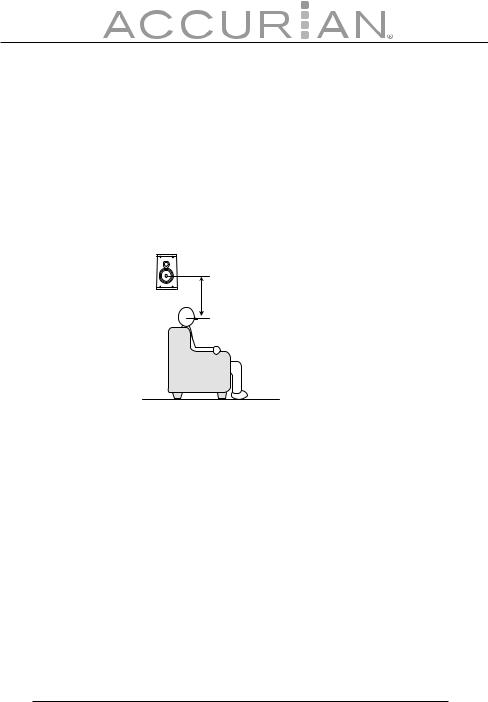
Surround Left and Right Speakers, and Surround Back Speaker
Place the surround left, right and surround back speakers higher than your ears by about 2.4-3.5’ (70 cm – 1 m). Also place the speakers at the same height, as best as possible.
2.4-3.5’
(0.7-1 m)
Note: Use magnetically-shielded speakers for the front left, right and center speakers when the speakers are installed near the TV and the TV is a monitor type.
14
Audio Components
TAPE DECK
|
|
AUDIO |
|
AUDIO |
|
|
|||||||
|
|
|
OUT |
|
|
IN |
|
|
|||||
|
|
L R |
|
L R |
|
|
|||||||
|
|
|
|
|
|
|
|
|
|
|
|
|
|
|
|
|
|
|
|
|
|
|
|
|
|
|
|
|
|
|
|
|
|
|
|
|
|
|
|
|
|
|
|
|
|
|
|
|
|
|
|
|
|
|
|
|
|
|
|
|
|
|
|
|
|
|
|
|
|
|
|
|
|
|
|
|
|
|
|
|
|
|
|
|
|
|
|
|
|
|
|
|
|
|
|
|
|
|
|
|
|
|
|
|
|
|
|
|
|
|
|
|
|
|
|
|
|
|
|
|
|
|
|
|
|
|
|
|
|
|
|
|
|
|
|
|
|
|
|
|
|
|
|
|
|
|
|
|
|
|
|
|
|
|
|
|
|
|
|
|
|
|
|
|
|
|
|
|
|
|
|
|
|
|
|
|
|
|
|
|
|
|
|
|
|
|
|
|
|
|
|
|
|
|
|
|
|
|
|
|
|
|
|
|
|
|
|
|
|
|
|
|
|
|
|
|
|
|
|
|
|
|
|
DIGITAL |
DIGITAL |
IN |
OUT |
DVD RECORDER
Tape Jacks
The audio output signal from the TAPE OUT (L/R) jack is the input jack (L/R) signal which is currently selected.
Notes:
•Insert all plugs and connectors securely. Incomplete connections may make noise.
•Be sure to connect the left and right channels properly. Red connectors are for the R (right) channel, and white connectors are for the L (left) channel.
15

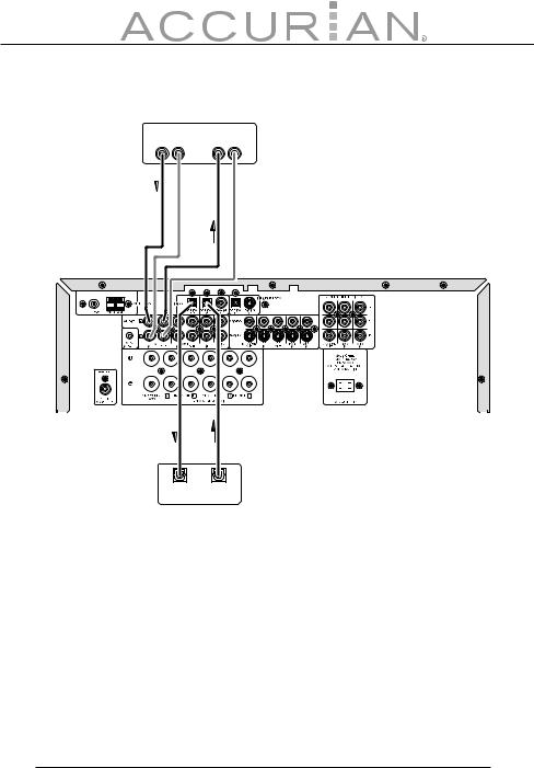
Connecting Digital Audio Components
•There are digital input jacks on the rear panel. You can use these jacks to input PCM, Dolby Digital and DTS bitstream signals from a CD, DVD, or other digital source components.
•There is one digital optical output jack on the rear panel. The jack can be connected to a CD recorder, DVD recorder, or MD deck inputs, respectively.
•To set up the digital audio format of DVD player, or other digital sources connected to digital input jacks, refer to the instructions of each component.
•You can designate the input for each digital input/output jack according to your component.
Notes:
•There is no Dolby Digital RF input jack. Please use an external RF demodulator Dolby Digital decoder when connecting the Dolby Digital RF output jack of the video disc player to the digital input jack.
•The digital signal jacks on this unit conform to the EIA standard. If you use a cable that does not conform to this standard, this unit may not function properly.
•Each type of audio jack works independently. Signals input through the digital and analog jacks are output through the corresponding digital and analog jacks, respectively.
•Digital input signals from the coaxial jack are also output from the optical jack.
16

Video Components
DVD PLAYER
AUDIO |
COMPONENT |
|
|
|
OUT |
VIDEO OUT |
DIGITAL |
VIDEO |
S-VIDEO |
R L |
Y Pb Pr |
OUT |
OUT |
OUT |
|
|
|
R L |
R |
L |
Y Pb Pr |
|
OUT |
IN |
IN OUT OUT IN |
COMPONENT |
S-VIDEO |
AUDIO |
VIDEO S-VIDEO |
VIDEO IN |
IN |
|
|
|
VCR |
VIDEO MONITOR OR PROJECTOR |
|
VIDEO, S-VIDEO, COMPONENT Jacks
There are 3 types of video jacks on the rear panel.
VIDEO Jack
The video signal for the VIDEO jacks is the conventional composite video signal.
17

S-VIDEO Jack
The video signal is separated into luminance (Y) and color (C) signals for the S-VIDEO jack. The S-VIDEO signals enable high-quality color reproduction. If your video component has an S-VIDEO output, we recommend to use it. Connect the S-VIDEO output jack on your video component to the S-VIDEO input jack on this unit.
COMPONENT Jack
Make component video connections to a TV or monitor with component inputs to produce higher quality video images. Use a component video cable or 3 video cords to connect the component video out jacks on the receiver to the monitor.
Video Convert
The receiver converts S-Video input signals to a video output signal. For example, the S-Video input signal can be output to the receiver’s MONITOR OUT VIDEO jack.
Notes:
•Be sure to connect the left and right audio channels properly. Red connectors are for the R (right) channel, and white connectors are for the L (left) channel.
•Be sure to connect the inputs and outputs of the video signals properly.
•If you connect the S-VIDEO or component signal to the S-VIDEO or component jack on this unit, it is not necessary to connect the conventional video signal to the VIDEO (composite) jack. If you use both video inputs, this unit gives priority to the S-VIDEO signal.
•Each type of video jack works independently. Signals input to the VIDEO (composite), S-VIDEO or component jacks are output to the corresponding VIDEO (composite), S-VIDEO, or component jacks, respectively.
•You may need to set up the digital audio output format of your DVD player, or other digital source components. Refer to the instructions of each component connected to the digital input jacks.
18
 Loading...