


TPS3 11
Surge Protective Device
User Manual - USA

V WARNING-Hazardous Voltage & Shock Hazard
Failure to Follow These Instructions Could Result in Death or Serious Injury
•Only qualified licensed electricians should install or service SPDs
•Hazardous voltages exist within SPDs
•SPDs should never be installed or serviced when energized
•Use appropriate safety precautions including Personal Protection Equipment
•Failure to follow these instructions can result in death, serious injury, and/or equipment damage.
•This manual shall be read in entirety prior to installing
Bonding and Grounding Hazard
Verify that the neutral conductor in the service entrance equipment is bonded to ground in accordance with the National Electrical Code (NEC®) and all applicable codes.
Verify that the neutral terminal (XO) on the secondary side of distribution transformers are grounded to the system ground in accordance with the NEC® and all applicable codes.
During installation into an electrical system the SPD must not be energized until the electrical system is completely installed, inspected and tested. All conductors must be connected and functional including the neutral (if required). The voltage rating of the SPD and system must be verified before energizing the SPD.
Failure to follow these guidelines can lead to abnormally high voltages at the SPD. This may cause the SPD to fail. The warranty is voided if the SPD is incorrectly installed and/or if the neutral conductor in the service entrance equipment or downstream of separately derived systems is not bonded to ground in accordance with the NEC®.
Do Not Hi-Pot Test SPDs
Any factory or on-site testing of power distribution equipment that exceeds normal operating voltage such as high-potential insulation testing, or any other tests where the suppression components will be subjected to higher voltage than their rated Maximum Continuous Operating Voltage (MCOV) must be conducted with the SPD disconnected from the power source. For 4-wire systems, the neutral connection at the SPD must also be disconnected prior to performing highpotential testing and then reconnected after test completion.
Failure to disconnect SPD and associated components during elevated voltage testing will damage the SPD and will void the warranty.
Table of Contents |
|
Failure to Follow These Instructions Could Result in Death or Serious Injury |
.............................. 2 |
Do Not Hi-Pot Test SPDs............................................................................................................................................................................. |
2 |
Introduction................................................................................................................................................... |
4 |
Warning and Safety Information................................................................................................................................................................ |
4 |
Qualified Person....................................................................................................................................................................................... |
4 |
Danger..................................................................................................................................................................................................... |
4 |
Warning.................................................................................................................................................................................................... |
4 |
Caution..................................................................................................................................................................................................... |
4 |
Do Not Hi-Pot Test SPDs............................................................................................................................................................................. |
4 |
Industry Standards Changes - 2009........................................................................................................................................................... |
4 |
Simplified Explanation of Operation.......................................................................................................................................................... |
5 |
Parts List and Inspection ........................................................................................................................................................................... |
5 |
Voltage Rating & Application..................................................................................................................................................................... |
5 |
SPDs on Ungrounded Systems................................................................................................................................................................... |
6 |
Optional Flush Mount Installation Instructions........................................................................................................................................... |
6 |
TPS3 11 Installation Instructions............................................................................................................... |
7 |
Common Problems to Avoid...................................................................................................................................................................... |
7 |
Operation.......................................................................................................................................................... |
9 |
Diagnostic Indication................................................................................................................................................................................ |
9 |
Phase indicator LEDs (Green)..................................................................................................................................................................... |
9 |
Service LED (Red)...................................................................................................................................................................................... |
9 |
Audible Alarm Option................................................................................................................................................................................ |
9 |
Dry Contact Option................................................................................................................................................................................... |
9 |
Remote Monitor Accessory Option............................................................................................................................................................. |
9 |
Maintenance.................................................................................................................................................. |
10 |
Troubleshooting & Service ...................................................................................................................................................................... |
10 |
Please contact us for any service related issues. ..................................................................................................................................... |
10 |
Warranty and Customer Service............................................................................................................... |
10 |
Limited Warranty.................................................................................................................................................................................... |
10 |
Technical Support................................................................................................................................................................................... |
10 |
Figures |
|
Figure 1: SPD Types.................................................................................................................................................................................. |
5 |
Figure 2: DIMENSIONS AND WEIGHT......................................................................................................................................................... |
5 |
Figure 3: Optional Flush Mount Installation.............................................................................................................................................. |
6 |
Figure 4: Conduit Installation................................................................................................................................................................... |
7 |
Figure 5: Typical Panel Installation............................................................................................................................................................ |
7 |
Figure 6: Installation Wiring Diagrams...................................................................................................................................................... |
8 |
Figure 7: Diagnostic Display...................................................................................................................................................................... |
9 |
Figure 8: Dry Contact Pin Configuration.................................................................................................................................................... |
9 |
Tables |
|
Table 1: Specifications |
|
................................................................................................................................................................................................................ |
5 |
Table 2: Model number decoder............................................................................................................................................................... |
6 |
Introduction
Thank you for choosing Siemens TPS3 Surge Protective Device (SPD). This is a high quality, high energy surge suppressor designed to protect sensitive equipment from damaging transient overvoltages.
Proper installation is important to maximize performance. Please follow the steps outlined herein.
This entire user manual should be read prior to beginning installation. These instructions are not intended to replace national or local codes. Follow all applicable electrical codes to ensure compliance. Installation of this SPD should only be performed by qualified electrical personnel.
All Siemens SPDs are extensively tested in accordance with industry standards such as ANSI/IEEE C62.41.1, C62.41.2, C62.45, C62.62, C62.72, UL 1449, UL 1283, IEC 61643, etc.
Warning and Safety Information
This equipment contains hazardous voltages. Death, serious injury, or property damage can result if safety instructions are not followed. Only qualified personnel should work on or around this equipment after becoming thoroughly familiar with all warnings, safety notices, and maintenance procedures contained herein.
The successful and safe operation of this equipment is dependent upon proper handling, installation, operation, and maintenance.
Qualified Person
For the purposes of this manual and product labels, a QUALIFIED PERSON is one who is familiar with the installation, construction, and operation of this equipment, and the hazards involved. In addition, he or she has the following qualifications:
(a)Is trained and authorized to energize, de-energize, clear, ground and tag circuits and equipment in accordance with established safety practices.
(b)Is trained in the proper care and use of personal protective equipment (PPE) such as rubber gloves, hard hat, safety glassesorfaceshields,flashclothing,etc.inaccordancewith established safety practices.
(c)Is trained in rendering first aid.
Danger
For the purposes of this manual and product labels, DANGER indicates an imminently hazardous situation, which, if not avoided, will result in death or serious injury.
Warning
For the purposes of this manual and product labels, WARNING indicates failure to following these instructions can result in death, serious injury, or equipment damage.
Caution
For the purposes of this manual and product labels, CAUTION indicates a potentially hazardous situation which, if not avoided, could result in minor or moderate injury.
These instruction do not purport to cover all details or variations in equipment, nor to provide for every possible contingency to be met
in connection with installation, operation or maintenance. Should further information be required by the user, please call Siemens TPS Tech Support at 1.888.333.3545 for assistance.
Do Not Hi-Pot Test SPDs
Any factory or on-site testing of power distribution equipment that exceeds normal operating voltage such as high-potential insulation testing, or any other tests where the suppression components will be subjected to higher voltage than their rated Maximum Continuous Operating Voltage (MCOV) must be conducted with the SPD disconnected from the power source. For 4-wire systems, the neutral connection at the SPD must also be disconnected prior to performing high-potential testing and then reconnected after test completion.
Failure to disconnect SPD and associated components during elevated voltage testing will damage the SPD and will void the warranty.
Industry Standards Changes - 2009
UL 1449 Third Edition and 2008 NEC® Article 285 generated substantial changes.
•The term TVSS changed to SPD
•Types 1, 2, 3 & 4 SPDs are created
•UL 1449 clamping voltage performance testing changed from 500A to 3,000A
•UL 1449 added new I nominal testing (In), which consists of more rigorous duty-cycle testing
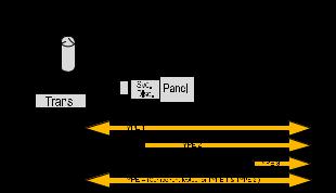
The SPD Type category is important to understand before installing any SPD. Type 1 and 2 SPDs are fully UL Listed devices whereas Type 4 SPDs are UL Recognized devices.
Type 1 – Installed on line or load side of the Main Overcurrent Protection (OCP), similar to what you knew as SSA, except now includes rigorous safety testing. Includes all OCP & safety disconnectors inside the SPD
Type 2 – Installed on load side of the Main OCP, similar to what you know as hardwired SPD, and it may require external OCP.
Type 3 – Point of Utilization, direct plug in type devices, similar to what you know as surge strips. Theses devices are intended for installation 10 meters from the panel (rational based on IEEE Cat. A location).
Type 4 – Surge suppression components, could be a basic component or a complete module. Type 4 components can be tested for Type 1, Type 2 or Type 3 applications.
Figure 1: SPD Types
2008 NEC Art 285 & UL 1449-3
SPD Types: Types 1, 2, 3, & 4
Based on Location within electrical distribution system
(also coincides with ANSI/IEEE C62.41.2 - 2002 Categories C, B &A)
 Loading...