


 Loading...
SIRIUS Motor Starter
M200D AS-Interface Basic
Manual • 03/2009
SIRIUS
Answers for industry.

SIRIUS
Motor starter
M200D AS-Interface Basic
Manual
03/2009
Introduction / product description
Product family
Functions
Installation / connection
Configuration / parameterization
Commissioning
Diagnostics
Technical specifications
Appendix
1
2
3
4
5
6
7
8
A
A5E01668085-01

Legal information
Warning notice system
This manual contains notices you have to observe in order to ensure your personal safety, as well as to prevent damage to property. The notices referring to your personal safety are highlighted in the manual by a safety alert symbol, notices referring only to property damage have no safety alert symbol. These notices shown below are graded according to the degree of danger.
 DANGER
indicates that death or severe personal injury will result if proper precautions are not taken.
 WARNING
indicates that death or severe personal injury may result if proper precautions are not taken.
 CAUTION
with a safety alert symbol, indicates that minor personal injury can result if proper precautions are not taken.
CAUTION
without a safety alert symbol, indicates that property damage can result if proper precautions are not taken.
NOTICE
indicates that an unintended result or situation can occur if the corresponding information is not taken into account.
If more than one degree of danger is present, the warning notice representing the highest degree of danger will be used. A notice warning of injury to persons with a safety alert symbol may also include a warning relating to property damage.
Qualified Personnel
The device/system may only be set up and used in conjunction with this documentation. Commissioning and operation of a device/system may only be performed by qualified personnel. Within the context of the safety notes in this documentation qualified persons are defined as persons who are authorized to commission, ground and label devices, systems and circuits in accordance with established safety practices and standards.
Proper use of Siemens products
Note the following:
 WARNING
Siemens products may only be used for the applications described in the catalog and in the relevant technical documentation. If products and components from other manufacturers are used, these must be recommended or approved by Siemens. Proper transport, storage, installation, assembly, commissioning, operation and maintenance are required to ensure that the products operate safely and without any problems. The permissible ambient conditions must be adhered to. The information in the relevant documentation must be observed.
Trademarks
All names identified by ® are registered trademarks of the Siemens AG. The remaining trademarks in this publication may be trademarks whose use by third parties for their own purposes could violate the rights of the owner.
Disclaimer of Liability
We have reviewed the contents of this publication to ensure consistency with the hardware and software described. Since variance cannot be precluded entirely, we cannot guarantee full consistency. However, the information in this publication is reviewed regularly and any necessary corrections are included in subsequent editions.
Siemens AG |
Ordernumber: 3RK1702-2BB11-1AA1 |
Copyright © Siemens AG 2009. |
Industry Sector |
03/2009 |
Technical data subject to change |
Postfach 48 48 |
|
|
90026 NÜRNBERG |
|
|
GERMANY |
|
|
Table of contents
1 |
Introduction / product description............................................................................................ |
................... 9 |
|
|
1.1 |
What are M200D distributed motor starters?................................................................................. |
9 |
|
1.2 |
Fieldbus interfaces....................................................................................................................... |
11 |
|
1.2.1 |
AS-Interface................................................................................................................................. |
11 |
2 |
Product family.......................................................................................................................................... |
13 |
|
|
2.1 |
Motor starter M200D AS-Interface............................................................................................... |
13 |
|
2.2 |
Overview of the device functions................................................................................................. |
14 |
|
2.3 |
Design concept............................................................................................................................ |
15 |
|
2.3.1 |
Operator controls......................................................................................................................... |
16 |
|
2.3.2 |
Connections................................................................................................................................. |
17 |
|
2.3.3 |
Status indicators .......................................................................................................................... |
18 |
3 |
Functions................................................................................................................................................. |
19 |
|
|
3.1 |
Overview of the device functions................................................................................................. |
19 |
|
3.2 |
Introduction .................................................................................................................................. |
20 |
|
3.3 |
Basic functions / parameters........................................................................................................ |
21 |
|
3.3.1 |
Rated operating current............................................................................................................... |
21 |
|
3.3.2 |
Protection against voltage failure................................................................................................. |
21 |
|
3.4 |
Fieldbus interface......................................................................................................................... |
22 |
|
3.5 |
Motor control................................................................................................................................ |
23 |
|
3.5.1 |
Control function: reversing starter................................................................................................ |
23 |
|
3.5.2 |
Brake output................................................................................................................................. |
23 |
|
3.6 |
Motor protection........................................................................................................................... |
25 |
|
3.6.1 |
Thermal motor model................................................................................................................... |
25 |
|
3.6.2 |
Temperature sensor..................................................................................................................... |
27 |
|
3.7 |
System monitoring....................................................................................................................... |
29 |
|
3.7.1 |
Current limit values...................................................................................................................... |
29 |
|
3.7.2 |
Asymmetry monitoring................................................................................................................. |
31 |
|
3.7.3 |
Inputs ........................................................................................................................................... |
32 |
|
3.7.4 |
Outputs......................................................................................................................................... |
35 |
|
3.7.5 |
Connector monitoring................................................................................................................... |
36 |
|
3.7.5.1 |
Power connector.......................................................................................................................... |
36 |
|
3.7.5.2 |
Motor connector........................................................................................................................... |
37 |
|
3.8 |
Short-circuit protection (circuit breaker / disconnecting means).................................................. |
38 |
|
3.9 |
Communication............................................................................................................................ |
38 |
|
3.9.1 |
Mode monitoring.......................................................................................................................... |
39 |
|
3.9.2 |
Plausibility check for settings....................................................................................................... |
39 |
|
3.9.3 |
Message output ........................................................................................................................... |
40 |
|
3.10 |
Trip reset...................................................................................................................................... |
41 |
|
3.11 |
Self-test........................................................................................................................................ |
41 |
M200D AS-Interface Basic |
5 |
||
Manual, 03/2009, A5E01668085-01 |
|||

Table of contents
|
3.12 |
Solid-state/mechanical switching technology.............................................................................. |
42 |
|
3.13 |
Local device interface ................................................................................................................. |
43 |
|
3.14 |
Integrated manual local control................................................................................................... |
44 |
4 |
Installation / connection........................................................................................................................... |
47 |
|
|
4.1 |
Installation................................................................................................................................... |
47 |
|
4.1.1 |
Installation rules.......................................................................................................................... |
47 |
|
4.1.2 |
Derating....................................................................................................................................... |
48 |
|
4.1.3 |
Installing the protection guards................................................................................................... |
51 |
|
4.1.4 |
Installing the motor starter.................................................................................................. |
......... 52 |
|
4.1.5 |
Functional ground ............................................................................................................. |
.......... 52 |
|
4.1.6 |
Setting the AS-i address ...................................................................................................... |
....... 53 |
|
4.2 |
Connection.................................................................................................................................. |
55 |
|
4.2.1 |
Required components/cables ..................................................................................................... |
55 |
|
4.2.2 |
Prefabricating power cables................................................................................................... |
..... 56 |
|
4.2.3 |
Installing and wiring power connectors....................................................................................... |
57 |
|
4.2.4 |
Power terminal............................................................................................................................ |
58 |
|
4.2.5 |
Brake output.................................................................................................................. |
.............. 60 |
|
4.2.6 |
Digital inputs/outputs................................................................................................................... |
62 |
|
4.2.6.1 |
Digital inputs................................................................................................................................ |
62 |
|
4.2.6.2 |
Digital output............................................................................................................................... |
63 |
|
4.2.7 |
AS-Interface................................................................................................................................ |
64 |
|
4.2.8 |
Connection options for AS-Interface........................................................................................... |
64 |
5 |
Configuration / parameterization.............................................................................................................. |
67 |
|
|
5.1 |
Configuration............................................................................................................................... |
67 |
|
5.2 |
Configuration on the AS-i master CP 343-2................................................................................ |
68 |
|
5.3 |
Parameterization......................................................................................................................... |
71 |
|
5.3.1 |
Parameterization......................................................................................................................... |
71 |
|
5.3.2 |
Parameterization via local setting............................................................................................... |
72 |
|
5.4 |
Process images........................................................................................................................... |
74 |
6 |
Commissioning........................................................................................................................................ |
75 |
|
|
6.1 |
Prerequisites............................................................................................................................... |
75 |
|
6.2 |
M200D AS-i components............................................................................................................ |
76 |
|
6.3 |
Procedure.................................................................................................................................... |
77 |
7 |
Diagnostics................................................................................................................... |
........................... 79 |
|
|
7.1 |
Diagnostics.................................................................................................................................. |
79 |
|
7.2 |
Diagnostics with LED.................................................................................................................. |
80 |
|
7.2.1 |
Statuses of the individual LEDs.................................................................................................. |
80 |
|
7.2.2 |
LED display combinations...................................................................................................... |
..... 82 |
|
7.3 |
Diagnostics via parameter channel (parameter echo)................................................................ |
84 |
|
7.4 |
Diagnostics with the addressing and diagnostics unit ................................................................ |
87 |
|
7.5 |
Troubleshooting .......................................................................................................................... |
87 |
|
7.5.1 |
Response to faults ...................................................................................................................... |
87 |
|
7.5.2 |
Acknowledging faults .......................................................................................................... |
........ 88 |
6 |
|
|
M200D AS-Interface Basic |
|
|
Manual, 03/2009, A5E01668085-01 |
|
|
|
|
Table of contents |
8 |
Technical specifications........................................................................................................................... |
89 |
|
|
8.1 |
General technical specifications .................................................................................................. |
89 |
|
8.2 |
Motor starter ................................................................................................................................. |
90 |
|
8.3 |
Brake control ................................................................................................................................ |
91 |
|
8.4 |
Inputs ........................................................................................................................................... |
92 |
|
8.5 |
Output .......................................................................................................................................... |
92 |
|
8.6 |
Thermistor motor protection ......................................................................................................... |
93 |
|
8.7 |
Switching frequency ..................................................................................................................... |
93 |
|
8.8 |
Electrical service life of contactor ................................................................................................. |
96 |
|
8.9 |
Dimension drawing ...................................................................................................................... |
98 |
A |
Appendix |
.................................................................................................................................................. |
99 |
|
A.1 |
Order numbers ............................................................................................................................. |
99 |
|
A.1.1 ............................................................................................................................. |
Order numbers |
99 |
|
A.1.2 ............................................................................................................ |
Spare parts/accessories |
100 |
|
A.2 ............................................................................................................................... |
Bibliography |
102 |
|
Glossary ................................................................................................................................................ |
|
105 |
|
Index...................................................................................................................................................... |
|
109 |
M200D AS-Interface Basic |
7 |
Manual, 03/2009, A5E01668085-01 |

Table of contents
8 |
M200D AS-Interface Basic |
Manual, 03/2009, A5E01668085-01 |
Introduction / product description |
1 |
1.1What are M200D distributed motor starters?
M200D motor starters are standalone devices with a high degree of protection (IP65) for distributed use near the motor.
Depending on the order variant, they are available as:
●Direct starters, electromechanical or electronic (DSte, sDSte)
●Reversing starters, electromechanical or electronic (RSte, sRSte)
They are suitable for the following tasks:
●Switching and protecting three-phase loads at 400 V AC up to 5.5 kW
●Control via AS-Interface
Depending on the order variant, they are equipped with:
●Brake output for 400 / 230 V AC or 180 V DC
●Integrated manual local control with a key-operated switch and keypad
M200D AS-Interface Basic |
9 |
Manual, 03/2009, A5E01668085-01 |
Introduction /product description
1.1 What are M200D distributed motor starters?
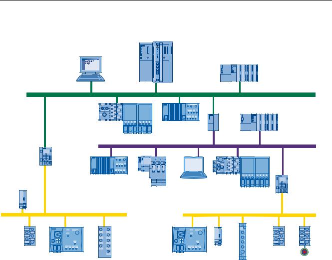
Connecting the M200D motor starter to AS-Interface
3& ZLWK 62)71(7 31 ,2
6 |
H J ZLWK |
&3 |
$GYDQFHG |
6 H J ZLWK &3
352),1(7
|
|
6 |
|
|
H J ZLWK &3 |
|
|
,( 3% |
|
|
/,1. |
|
* ' |
|
(7 SUR |
|
|
|
|
31 ,2 |
|
,( $6 L |
|
/,1. |
|
31 ,2 |
3RZHU |
|
|
* ' |
VXSSO\ XQLW |
|
(7 6 |
|
|
352),%86 |
|
|
'3 $6 L |
|
(7 SUR |
|
|
|
/,1. |
3* H J |
|
|
|
|
$GYDQFHG |
ZLWK &3 |
|
|
$6 ,17(5)$&( |
|
|
$6 ,17(5)$&( |
6ODYH |
|
|
|
|
|
|
|
|
3RZH |
|
6ODYH |
|
|
|
U |
|
|
|
|
|
|
|
6ODYH ZLWK |
0 ' |
6ODYH |
0 ' |
|
|
|
|
|
|
VXSSO |
6ODYH |
|
|
|
|
|
|
(0(5*(1 |
|
|
|
\ XQLW |
|
|
|
|
|
|
|
&< 6723 |
Figure 1-1 M200D: overview
M200D AS-Interface Basic
10 |
Manual, 03/2009, A5E01668085-01 |
Introduction /product description 1.2 Fieldbus interfaces
1.2Fieldbus interfaces
1.2.1AS-Interface
Overview
The AS-Interface (actuator sensor interface, AS-i) is an open international standard for fieldbus communication between distributed actuators and sensors at the lowest control level.
AS-i complies with the IEC 61158 / EN 50295 standards and was specifically designed for connecting binary sensors and actuators that comply with these standards. AS-i makes it possible to replace point-to-point cabling of the sensors and actuators by a bus line.
|
|
3RZHU VXSSO\ XQLWV |
|
3/& |
$6 L PDVWHU |
8$6 L |
8$8; 9 '& |
|
$6 L /LQN |
|
|
(QHUJ\ LQIHHG |
|
|
|
|
0RWRU VWDUWHU |
|
|
|
0 ' |
|
|
Figure 1-2 Example: M200D AS-i
The AS-Interface has the following advantages:
●Flexibility
●Cost effectiveness
●Simple and rapid installation with a minimum of errors
●A common line for transferring data and power
M200D AS-Interface Basic |
11 |
Manual, 03/2009, A5E01668085-01 |

Introduction /product description 1.2 Fieldbus interfaces
Further information
●Catalogs, customer magazines, and brochures are available on the Internet (http://www.automation.siemens.com/net/html_00/support/presales.htm)
●Brochure "Industrial communication for automation" (http://www.automation.siemens.com/download/internet/cache/3/1462730/pub/en/bs_kschrift_en_0408.pdf)
(Introductory information about industrial communication):
●Catalog IK PI 2009 "Industrial Communication for Automation and Drives" (http://www.automation.siemens.com/net/html_76/support/printkatalog.htm) (Device overview and ordering data for industrial communication)
●"AS-Interface - The Solution for Automation" (http://www.asinterface.net/EN/System/Publications?)
(Compendium of technology, function and applications):
●AS-Interface homepage (http://www.as-interface.net/EN/Homepage?)
12 |
M200D AS-Interface Basic |
Manual, 03/2009, A5E01668085-01 |
Product family |
2 |
2.1Motor starter M200D AS-Interface
The following motor starters with AS-Interface (AS-i) are available:
●M200D AS-i Basic
motor starter with thermistor motor protection + electronic motor model:
–Direct starter (electromechanical) (DSte) up to 5.5 kW, Current ranges: 0.15 – 2 A and 1.5 – 12 A
–Reversing starter (electromechanical) (RSte) up to 5.5 kW, Current ranges: 0.15 – 2 A and 1.5 – 12 A
–Direct starter (electronic) (sDSte) up to 4 kW, Current ranges: 0.15 – 2 A and 1.5 – 9 A
–Reversing starter (electronic) (sRSte) up to 4 kW, Current ranges: 0.15 – 2 A and 1.5 – 9 A
Order variants:
●Brake output for:
–400/230 V AC
–180 V DC
●Integrated manual operation (key-operated switch and keypad)
Accessories:
●Connection components (e.g. cables, connectors, etc.)
●Hand-held device
●Protection guard for the plug connections
M200D AS-Interface Basic |
13 |
Manual, 03/2009, A5E01668085-01 |

Product family
2.2 Overview of the device functions
2.2 |
Overview of the device functions |
|
|
|
|
|
|
|
|
Device functions |
Electromechanical (DSte, RSte)/ |
|
|
|
electronic (sDSte, sRSte) |
|
|
Fieldbus interface |
● |
|
|
Control function: reversing starter |
○ |
|
|
Control function: soft starter |
— |
|
|
Brake output 400 V / 230 V AC |
○ |
|
|
Brake output 180 V DC |
○ |
|
|
Thermal motor model |
● |
|
|
Temperature sensor (thermistor motor protection) |
● |
|
|
Asymmetry monitoring |
● |
|
|
Blocking current monitoring |
● |
|
|
Zero-current monitoring |
● |
|
|
M12 inputs (routed via AS-i) |
4 (2) |
|
|
M12 outputs (routed via AS-i) |
1 (0) |
|
|
Connector monitoring |
● |
|
|
Short-circuit protection |
● |
|
|
Communication |
|
|
|
Slave type |
A/B slave (4I / 3O) |
|
|
Communication profile |
7.A.E |
|
|
Diagnostics via parameter channel (parameter echo) |
● |
|
|
Support for AS-i S1 status bit |
● |
|
|
Transfer of data sets via AS-i |
— |
|
|
Extended cyclic process image |
— |
|
|
Access via "Motor Starter ES" |
— |
|
|
Additional functions |
|
|
|
Self-test |
● |
|
|
Local device interface |
● |
|
|
Disconnecting means |
● |
|
|
Integrated manual local control |
○ |
|
|
(key-operated switch, keypad with LEDs) |
|
|
|
Setting elements parameterized on device |
● |
|
|
● Integrated |
|
|
|
○ Order variant |
|
14 |
M200D AS-Interface Basic |
Manual, 03/2009, A5E01668085-01 |
Product family 2.3 Design concept
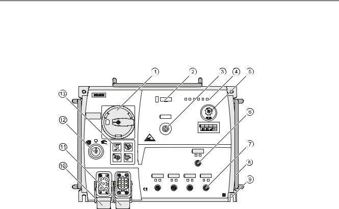
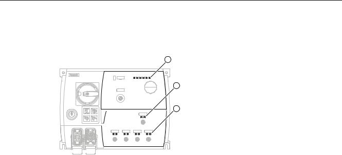
2.3Design concept
Connections and controls on the motor starter
$6L |
$8; |
|
|
6) '(9 )$8/7 67$7 3:5 |
3:5 |
|
|
0,4 |
0,6 |
0,8 |
|
0,3 |
|
|
1 |
|
|
|
1,2 |
0,2 |
0,15 CLASSOFF 2A1,81,5 |
||
le |
|
|
|
; |
|
|
|
|
|
|
|
RQ |
7& |
RQ |
RII |
RII |
37& |
RII |
RQ |
|
|
; |
|
287
,1 |
,1 |
,1 |
,1 |
; |
; |
Disconnecting means (circuit breaker), can be lockedOptical device interface
M12 AS-i connection
Diagnostic LEDs
Cover (setting elements)M12 output
M12 inputs
Protection guard for cables and connections (accessories)Fixing holes for installation
400 V infeed
Motor connection
Key-operated switch (order variant)
Keypad for manual operation (order variant)
M200D AS-Interface Basic |
15 |
Manual, 03/2009, A5E01668085-01 |
Product family 2.3 Design concept
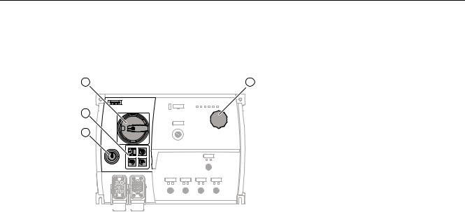
2.3.1Operator controls
The motor starter is equipped with the following operator controls:
|
|
Key-operated switch (order variant)
Keypad (order variant)
Disconnecting means (circuit breaker)
Cover for parameter setting elements
Integrated manual local control (key-operated switch and keypad ; order variant)
A key-operated switch and keypad are used for local operation. The key can be inserted/removed in three positions.
Disconnecting means (circuit breaker)
The disconnecting means is designed for the following individual functions:
●Disconnecting the series-connected consumers from the supply voltage
●Short-circuit protection of the series-connected consumer
●Switching on inhibited via padlock (max. three padlocks possible)
Parameter settings
The following setting elements can be found under the cover of the M200D AS-i Basic:
●Rotary coding switch for:
–Setting the rated operating current
–Deactivating the thermal motor model (class OFF)
●DIP switch for:
–Autoreset (ON / OFF)
–Connector monitoring (ON / OFF)
–Temperature sensor (ON / OFF)
–Temperature sensor (PTC / TC)
16 |
M200D AS-Interface Basic |
Manual, 03/2009, A5E01668085-01 |
Product family 2.3 Design concept
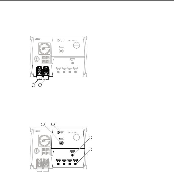
2.3.2Connections
Power terminals
Infeed for the three phases as well as the PE and N conductor via power connectors (HAN Q4/2 with ISO23570 assignment)
Connection of the motor via power connectors (HAN Q8/0 with ISO23570 assignment)
Control circuit / bus
AS-i bus connection with auxiliary voltage, M12 connector
Optical device interface (under the labeling strip) for connecting the hand-held device1 x M12 output
4 x M12 inputs
•2 inputs can be read via AS-i
•2 inputs with fixed input function
M200D AS-Interface Basic |
17 |
Manual, 03/2009, A5E01668085-01 |
Product family 2.3 Design concept
2.3.3Status indicators
The following LEDs on the front of the starter indicate the device status:
Indicators for the device status and communication
Indicator for output OUT1
Indicators for inputs IN1 ... IN4
For a detailed description of the indicators, see "Diagnostics (Page 80)".
18 |
M200D AS-Interface Basic |
Manual, 03/2009, A5E01668085-01 |
Functions |
3 |
3.1 |
Overview of the device functions |
|
|
|
|
|
|
|
|
Device functions |
Electromechanical (DSte, |
|
|
|
RSte)/ |
|
|
|
electronic (sDSte, sRSte) |
|
|
Fieldbus interface (Page 22) |
● |
|
|
Control function: reversing starter (Page 23) |
○ |
|
|
Brake output 400 V / 230 V AC (Page 23) |
○ |
|
|
Brake output 180 V DC (Page 23) |
○ |
|
|
Thermal motor model (Page 25) |
● |
|
|
Temperature sensor (thermistor motor protection) (Page 27) |
● |
|
|
Blocking protection (Page 29) |
● |
|
|
Zero-current monitoring (Page 29) |
● |
|
|
Asymmetry monitoring (Page 31) |
● |
|
|
M12 inputs (routed via AS-i) (Page 32) |
4 (2) |
|
|
M12 outputs (routed via AS-i) (Page 35) |
1 (0) |
|
|
Connector monitoring (Page 36) |
● |
|
|
Short-circuit protection (Page 38) |
● |
|
|
Communication |
|
|
|
Slave type |
A/B slave (4I / 3O) |
|
|
Communication profile (Page 68) |
7.A.E |
|
|
Diagnostics via parameter channel (parameter echo) (Page 84) |
● |
|
|
Support for AS-i S1 status bit (Page 84) |
● |
|
|
Transfer of data sets via AS-i |
— |
|
|
Extended cyclic process image |
— |
|
|
Access via "Motor Starter ES" |
— |
|
|
Additional functions |
|
|
|
Self-test (Page 41) |
● |
|
|
Local device interface (Page 43) |
● |
|
|
Disconnecting means (Page 38) |
● |
|
|
Integrated manual local control (Page 44) |
○ |
|
|
(key-operated switch, keypad with LEDs) |
|
|
|
Setting elements parameterized on device (Page 72) |
● |
|
|
● Integrated |
|
|
|
○ Order variant |
|
See also
Communication (Page 38)
M200D AS-Interface Basic |
19 |
Manual, 03/2009, A5E01668085-01 |
Functions
3.2 Introduction
3.2Introduction
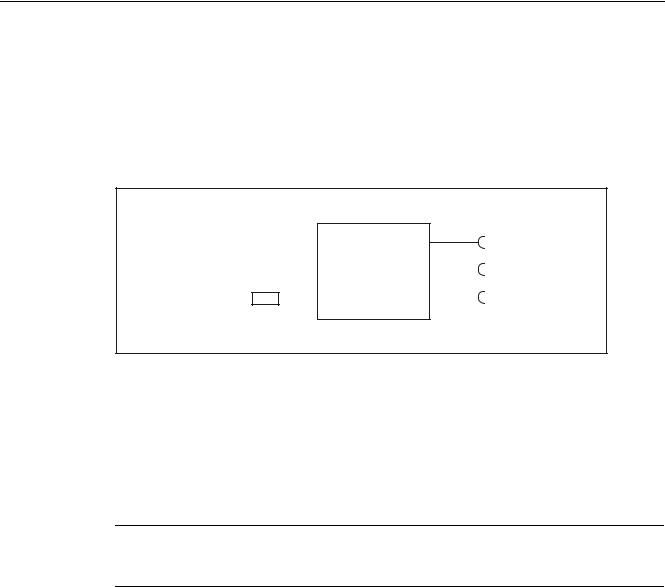
Device functions
This section describes the device functions. All the device functions are assigned inputs (e.g. device parameters) and outputs (e.g. messages).
The following schematic diagram illustrates the functional principle of the device:
,QSXWV |
|
|
|
|
|
|
|
|
|
|
|
|
|
|
|
|
2XWSXWV |
'HYLFH SDUDPHWHUV |
|
|
|
|
|
|
|
|
|
|
|
|
|
|
|
||
|
|
|
|
|
|
|
|
0HDVXUHG YDOXHV |
&RPPDQGV |
|
|
|
|
'HYLFH IXQFWLRQ |
|
$ODUPV |
|
|
|
|
|
|
||||
|
|
|
|
|
||||
|
|
|
|
|
|
|
|
$FWLRQV |
|
|
|
|
|
|
|
|
|
|
|
|
|
|
|
|
|
|
3URWHFWLRQ |
|
|
|
|
|
|
|
|
Figure 3-1 Functional principle of the device
Self-protection
The motor protects itself against fatal damage by means of the thermal motor model and temperature measurements for electronic switching elements.
Currents
Note
All current values (e.g. blocking current, current limits) are percentages of the rated operating current set on the device (e.g. Ie = 2 A = 100 %).
20 |
M200D AS-Interface Basic |
Manual, 03/2009, A5E01668085-01 |
Functions 3.3 Basic functions /parameters
3.3Basic functions / parameters
Definition
Basic parameters are "central" parameters required by a range of device functions.
3.3.1Rated operating current
Here, you can enter the rated operating current that the branch (switchgear and motor) can carry without interruption. This is usually the rated motor current. The setting range depends on the output class of the M200D motor starter (0.15 ... 2 A or 1.5 ... 12 A).
NOTICE
The rated operating current is one of the key parameters.
The rated operating current must always be set if motor protection is to be ensured via the electronic overload relay.
The overload relay can be deactivated.
In this case, motor protection must be ensured by means of a thermistor in the motor.
Notes
●On the motor starter, the default rated operating current is set to the minimum value.
●The rated operating current for the M200D AS-i Basic motor starter is set by means of the rotary coding switch. For more information, see Parameterization via local setting
(Page 72).
3.3.2Protection against voltage failure
If the supply voltage fails, the last overload message "Overload" is retained.
M200D AS-Interface Basic |
21 |
Manual, 03/2009, A5E01668085-01 |

Functions
3.4 Fieldbus interface
3.4Fieldbus interface
Response to CPU / master STOP
If the fieldbus interface is interrupted, all control signals are set to 0.
Note
This is only relevant in "automatic" mode.
Group diagnosis
The controller is informed of whether or not a group fault message is present in the device when "I/O fault bits" on the SAP status tab (S1 = 1) is set. The AS-i master enters the S1 value in the list of I/O faults (LPF) that have been signaled. The controller can read this list via the "GET_LPF" command and then query a specific diagnostic value from the slave (see also Diagnostics via parameter channel (parameter echo) (Page 84)).
The motor starter issues a fault message if a fault is present. In this case, the SF LED lights up red.
Reference
For more information, refer to the documentation for your AS-i master.
22 |
M200D AS-Interface Basic |
Manual, 03/2009, A5E01668085-01 |
Functions 3.5 Motor control
3.5Motor control
3.5.1Control function: reversing starter
Description
This control function allows the motor starter to control the direction in which motors rotate. An internal logic prevents both directions of rotation from being activated simultaneously. The delayed switchover from one direction of rotation to another is implemented by means of the lock-out time, which is permanently set to 150 ms.
This function only applies to reversing starters.
3.5.2Brake output
Description
A motor-mounted mechanical disk or spring-loaded brake is used to brake the motor. The brake is controlled via the brake output.
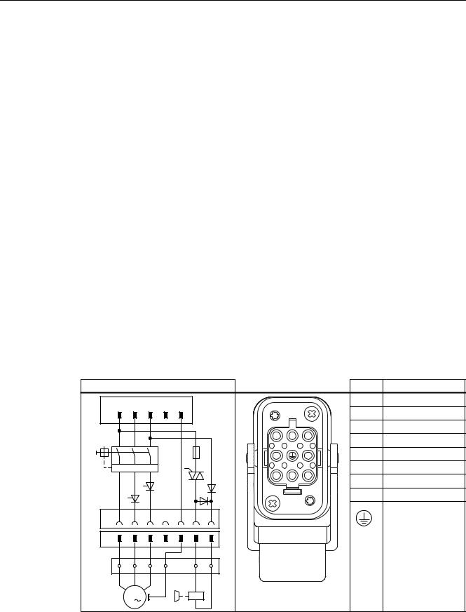
Circuit diagram: example
The following circuit diagram illustrates the mechanical braking procedure with a 180 V DC brake output:
Circuit diagram |
|
|
|
|
Motor connector |
|
Pin |
Name |
||
/ |
/ |
/ |
1 |
3( |
|
|
|
|
1 |
Phase L1 |
; |
|
|
|
3( |
|
|
|
|
2 |
— |
|
|
|
|
|
|
|
|
|
3 |
Phase L3 |
|
|
|
|
|
|
|
|
|
4 |
Brake L1 (switched) |
|
|
|
|
|
|
|
|
|
||
|
|
|
|
|
|
|
|
|
5 |
Thermistor |
,!! |
,!! |
,!! |
|
|
|
|
|
|
6 |
Brake L3 (direct) |
|
|
|
|
|
|
|
|
|
||
|
|
|
|
|
|
|
|
|
7 |
Phase L2 |
|
|
|
|
|
|
|
|
|
||
|
|
|
|
|
|
|
|
|
8 |
Thermistor |
|
|
|
|
|
|
|
|
|
|
PE (yellow/green) |
; |
|
|
|
3( |
|
|
|
|
|
|
|
|
|
|
3( |
|
|
|
|
|
|
|
|
|
|
|
|
|
; |
|
|
|
|
0 |
|
|
|
|
|
|
|
|
|
|
|
|
|
|
|
|
|
|
|
|
M200D AS-Interface Basic
Manual, 03/2009, A5E01668085-01 |
23 |

Functions
3.5 Motor control
Brake output
Externally-supplied motor brakes are usually powered via a jumper on the motor terminal board.
Since switching the motor and brake simultaneously can increase wear and tear to the brake, all M200D motor starters can be fitted with an optional electronic brake controller.
Depending on the order variant, the following externally-supplied brake coils can be controlled:
●400 V AC / 230 V
(The brake rectifier must be installed in the motor. The rectifier input is controlled via the motor starter).
●180 V DC
(A rectifier is not required for the brake in the motor because the motor starter provides the 180 V DC. In this way, brake coils for 180 V DC can be switched directly).
The brake voltage is fed to the motor together with the motor infeed via a joint cable (e.g. 6 x 1.5 mm2). For more information about connecting the brake output, see section Brake output (Page 60).
Brake release delay at startup
A fixed ON-delay time of 40 ms is set for the M200D AS-i Basic motor starter to prevent wear and tear to the brake (e.g. the motor output is activated 40 ms after the brake output).
In reversing mode, the release delay does not begin until the lock-out time has expired.
24 |
M200D AS-Interface Basic |
Manual, 03/2009, A5E01668085-01 |

Functions 3.6 Motor protection
3.6Motor protection
3.6.1Thermal motor model
Description
The approximate temperature of the motor is calculated using the measured motor currents and device parameters "Rated operating current" and "Tripping class". This indicates whether the motor is overloaded or functioning in the normal operating range.
Motor protection shutdown response
You use this device parameter to specify how the motor starter is to respond in an overload situation:
●Shutdown without restart (AUTO RESET = off)
Following an overload situation, the shutdown command cannot be reset until the motor model has fallen below the reset threshold and after a reset command has been issued (trip reset).
●Shutdown with restart (AUTO RESET = on)
 WARNING
Motor restarts automatically if AUTO RESET is on. Can Cause Death, Serious Injury, or Property Damage
The motor starter restarts automatically after the recovery time if a start command is present (autoreset). (autoreset).
Make sure that you take appropriate measures to exclude the risk of hazardous conditions.
M200D AS-Interface Basic |
25 |
Manual, 03/2009, A5E01668085-01 |
Functions
3.6 Motor protection
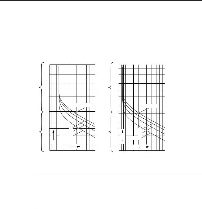
Trip class
The trip class (CLASS) specifies the maximum time within which a protective device must trip from a cold state at 7.2 x the setting current (motor protection to IEC 60947). The M200D AS-i Basic trip class is set permanently to CLASS 10 and can be deactivated.
If the setting is changed to CLASS OFF, the "thermal motor model" function is deactivated along with the accompanying messages. With the M200D AS-i Basic, the thermal motor model is deactivated by means of the rotary coding switch for setting the operating current (CLASS OFF position).
|
|
|
|
|
|
|
|
|
|
|
|
|
|
|
|
|
|
|
|
|
|
|
|
|
|
|
|
|
|
|
|
|
|
|
|
|
|
|
|
|
|
|
|
|
|
|
|
|
|
|
|
|
|
|
|
0LQ |
|
|
|
|
|
|
0LQ |
|
|
|
|
|
|
|
|
|
|
|
|
|
|
|
|
|
|
|
|
|
|
|
|
|
|
|
|
|
|
|
|
|
|
|
|
|
|
|
&/$66 |
|
|
|
|
|
|
|
|
|
|
|
|
|
|
|
|
|
|
|
|
&/$66 |
|
|
|
|
|
|
|
|
|
|
|
|
|
|
|
|
|
|
|
|
|
|
|
|
|
|
|
|
|
|
|
|
|
|
|
|
|
|
|
|
|
|
|
|
|
|
|
|
|
|
|
|
|
|
|
|
|
|
|
|
|
|
|
|
|
|
|
|
|
|
|
V |
|
|
|
|
|
|
V |
|
|
|
|
|
|
|
|
|
|
|
|
|
|
|
|
|
|
||
|
|
|
|
|
|
|
|
|
|
|
|
|
|
|
|
|
|
|
|
|
|
|
|
|
|
|
|
|
|
|
|
|
|
|
|
|
|
|
|
|
|
|
|
|
|
&/$66 |
|
|
|
|
|
|
|
|
|
|
|
|
|
|
|
|
|
|
|
|
&/$66 |
|
|
|
|
A |
|
|
|
|
|
|
A |
|
|
|
|
|
|
t |
|
|
|
|
|
|
t |
|
|
|
|
|
|
|
|
[Ie |
|
|
|
|
|
|
[Ie |
|
|
|
|
|
|
|
|
|
|
|
|
|
|
||
|
|
|
|
|
|
|
|
|
|
|
|
|
|
|
|
|
|
|
|
|
|
|
|
|
|
||
|
SROH V\PPHWULFDO ORDG |
|
|
SLQ ORDG |
|
|
|||||||
|
|
|
|
|
|
|
|
IDLOXUH RI SKDVH RU |
|
|
|||
|
|
|
|
|
|
|
|
FXUUHQW LPEDODQFH ! |
|
||||
Note |
|
|
|
|
|
|
|
|
|
|
|
|
|
Deactivation rule
To ensure motor protection, the motor cannot be switched on when the temperature sensor is deactivated and, at the same time, CLASS OFF is set. This is indicated on the M200D AS- i Basic with either an alarm (if an ON command is not present) or a fault (if an ON command is present).
Recovery time
The recovery time is the time defined for cooling after which the system can be reset following an overload trip. The recovery time for the M200D AS-i Basic is set permanently to 90 s.
Trip reset signals present during the recovery time have no effect.
Voltage losses occurring before this time expires can prolong the recovery time.
M200D AS-Interface Basic
26 |
Manual, 03/2009, A5E01668085-01 |

Functions 3.6 Motor protection
Prewarning limit for motor heating
The motor starter also assumes a prewarning role, that is, it issues a warning if the motor temperature limit is exceeded. The prewarning limit for the M200D AS-i Basic is 90 % of the motor heating value. The motor is shut down at 100 %.
The alarm can be read via Diagnostics via parameter channel (parameter echo) (Page 84) for the starter.
Settings
Device parameter |
Default setting |
|
Setting range |
Motor protection shutdown |
Shutdown without restart |
• |
Shutdown without restart |
response |
|
• |
Shutdown with restart |
|
|
|
|
Trip class |
CLASS 10 |
• |
CLASS 10 |
|
|
• |
CLASS OFF |
|
|
|
|
3.6.2Temperature sensor
Description
Temperature sensors are used to directly monitor the motor winding temperature. This indicates whether the motor is overloaded or functioning normally. If temperature sensors are installed in the motor stator winding (order option for the motor), the M200D motor starter can use these to monitor the motor.
M200D motor starters can evaluate one temperature sensor circuit.
Temperature sensor
You can activate or deactivate this parameter depending on whether or not a temperature sensor is installed in the motor. The setting is made by means of the DIP switch on the device.
Two types of temperature sensor are supported:
●Thermoclick.
This is a switch that opens at a certain winding temperature.
●PTC type A.
This is a PTC thermistor with a characteristic to IEC 60947-8.
When the PTC type A temperature sensor is active, temperature sensor monitoring is also activated (see below).
M200D AS-Interface Basic |
27 |
Manual, 03/2009, A5E01668085-01 |

Functions
3.6 Motor protection
Motor protection shutdown response
You can use this parameter to determine how the motor starter is to respond to a temperature sensor or thermal motor model overload:
●Shutdown without restart (AUTO RESET = off)
●Shutdown with restart (AUTO RESET = on)
 WARNING
Motor restarts automatically if AUTO RESET is on. Can Cause Death, Serious Injury, or Property Damage
The motor starter restarts automatically after the recovery time if a start command is present (autoreset). (autoreset).
Make sure that you take appropriate measures to exclude the risk of hazardous conditions.
Temperature sensor monitoring
Temperature sensor monitoring is activated when a PTC type A temperature sensor is parameterized.
This device parameter monitors the temperature sensor cable for interruptions (wire breakage) and short-circuits. The motor is shut down if either of these scenarios occurs.
Settings
The possible settings for the M200D AS-i Basic motor starter can be found in section Parameterization via local setting (Page 72).
28 |
M200D AS-Interface Basic |
Manual, 03/2009, A5E01668085-01 |

Functions 3.7 System monitoring
3.7System monitoring
3.7.1Current limit values
Description
The motor current and current limit values can be used to determine different system statuses:
System status |
Current value |
Protection by |
Motor blocked |
Very high current flowing |
Blocking protection |
Motor runs at no load (e.g. |
Very low current flowing |
Residual current detection |
because system is damaged) |
(< 18.75 % of Ie) |
|
Response to residual current detection
Residual current detection responds when the motor current in all three phases falls below 18.75 % of the set rated operating current. In this case, the motor starter shuts down the motor.
Residual current detection is deactivated by setting the rotary coding switch to "CLASS OFF".
Note
When the motor is switched on, residual current detection is suppressed for around 1 second.
Blocking current monitoring
The blocking current specifies how much current is consumed by the motor (at rated voltage) when the axis blocked.
The blocking current monitoring function detects when a motor axis is blocked mechanically. The block causes the motor to consume more power. The "blocking current" is a defined monitoring threshold for the motor current consumption.
It is monitored as follows:
When the motor starts, the tripping limit for the blocking current is set permanently to 800 % of the rated operating current for a period of 10 s. During operation, the "blocking current" tripping limit is set permanently to 400 % of the rated operating current.
If the blocking current is exceeded, the motor starter detects blocking. Blocking time monitoring is activated as of the point at which the blocking current is exceeded. If the blocking current flows for longer than the blocking time, the motor starter automatically generates a shutdown command.
M200D AS-Interface Basic |
29 |
Manual, 03/2009, A5E01668085-01 |
Functions
3.7 System monitoring
The blocking current monitoring function is deactivated by setting the rotary coding switch to "CLASS OFF".
Note
If the blocking time expires and the system is still blocked, the motor starter is shut down.
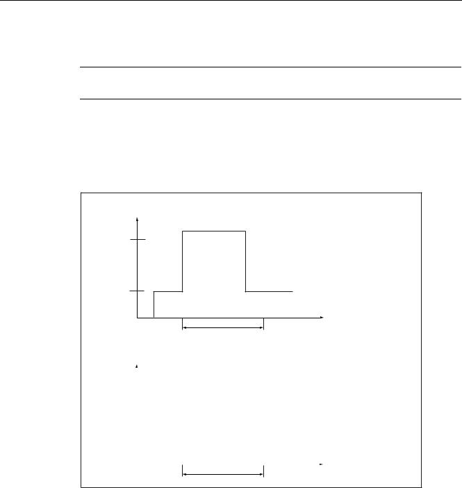
Blocking time
The blocking time is the time a block can be present before the motor shuts down. If the blocking time expires and the system is still blocked, the motor starter is shut down. The blocking time in the M200D AS-i Basic is set permanently to 1 s.
6FHQDULR 0RWRU FRQWLQXHV WR UXQ
6WDOOHG URWRU
%ORFNLQJ
FXUUHQW %ORFN FDQFHOHG ZLWKLQ EORFNLQJ WLPH
0RWRU FRQWLQXHV WR UXQ
0RWRU FXUUHQW
%ORFNLQJ WLPH W
6FHQDULR 0RWRU LV VKXW GRZQ
|
|
|
|
|
6WDOOHG URWRU |
||
%ORFNLQJ |
|
|
|
|
|
|
|
|
|
|
|
|
|
||
FXUUHQW |
|
|
|
|
|
|
|
|
|
|
|
|
|
%ORFN VWLOO SUHVHQW DIWHU EORFNLQJ |
|
|
|
|
|
|
|
WLPH KDV HODSVHG |
|
0RWRU |
|
|
|
|
|
|
|
|
|
|
|
|
|
0RWRU LV VKXW GRZQ |
|
|
|
|
|
|
|
||
FXUUHQW |
|
|
|
|
|
|
|
|
|
|
|
|
|
|
|
%ORFNLQJ WLPH |
|
|
W |
Figure 3-2 Block protection principle
30 |
M200D AS-Interface Basic |
Manual, 03/2009, A5E01668085-01 |
Loading...