


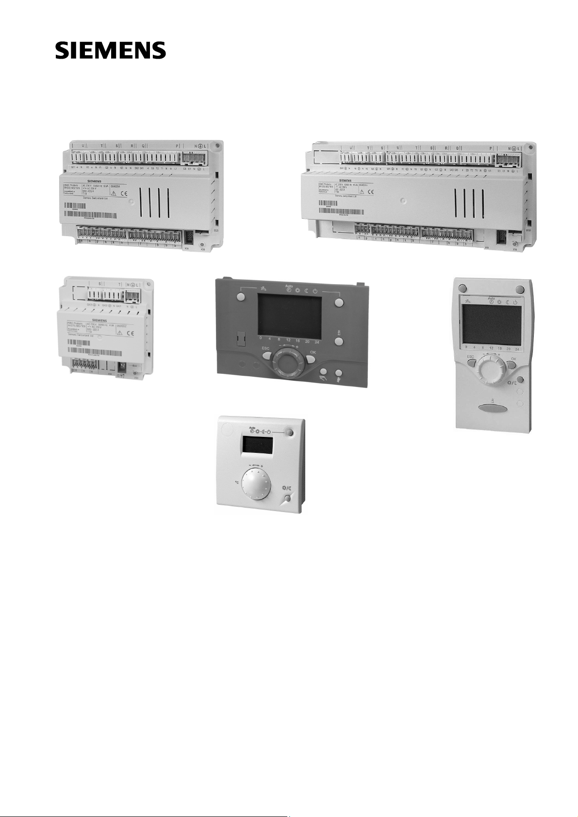
RVS43
Siemens RVS43, RVS63, AVS75, AVS37, QAA75 User Guide
...
Edition 3.0
Controller series B
CE1U2354en
23. August 2007
Building Technologies
HVAC Products
Albatros
2
Boiler controller
User Manual
RVS43..
RVS63..
AVS75..
AVS37..
QAA75..
QAA78..
QAA55..

2/180
Siemens Schweiz AG User Manual CE1U2354en
HVAC Products 23. August 2007

3/180
Siemens Schweiz AG User Manual CE1U2354en
HVAC Products 23. August 2007
Contents
1 Summary ......................................................................................................... 9
1.1 Type summary............................................................................................... 10
1.1.1 Topology........................................................................................................ 10
2 Safety notes................................................................................................... 12
2.1 Product liability ..............................................................................................12
3 Mounting and installation............................................................................... 13
3.1 Regulations.................................................................................................... 13
Electrical installation ......................................................................................13
3.2 Basic units RVS… ......................................................................................... 13
Engineering ...................................................................................................13
Mounting method........................................................................................... 14
Dimensions and drilling plan.......................................................................... 14
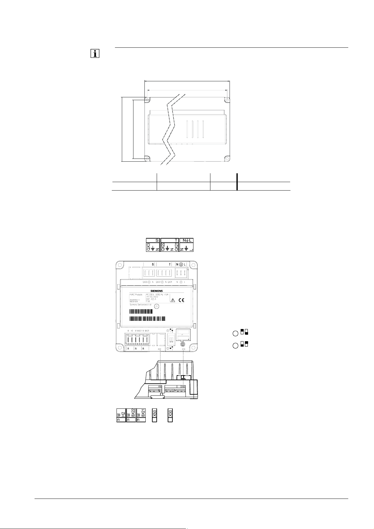
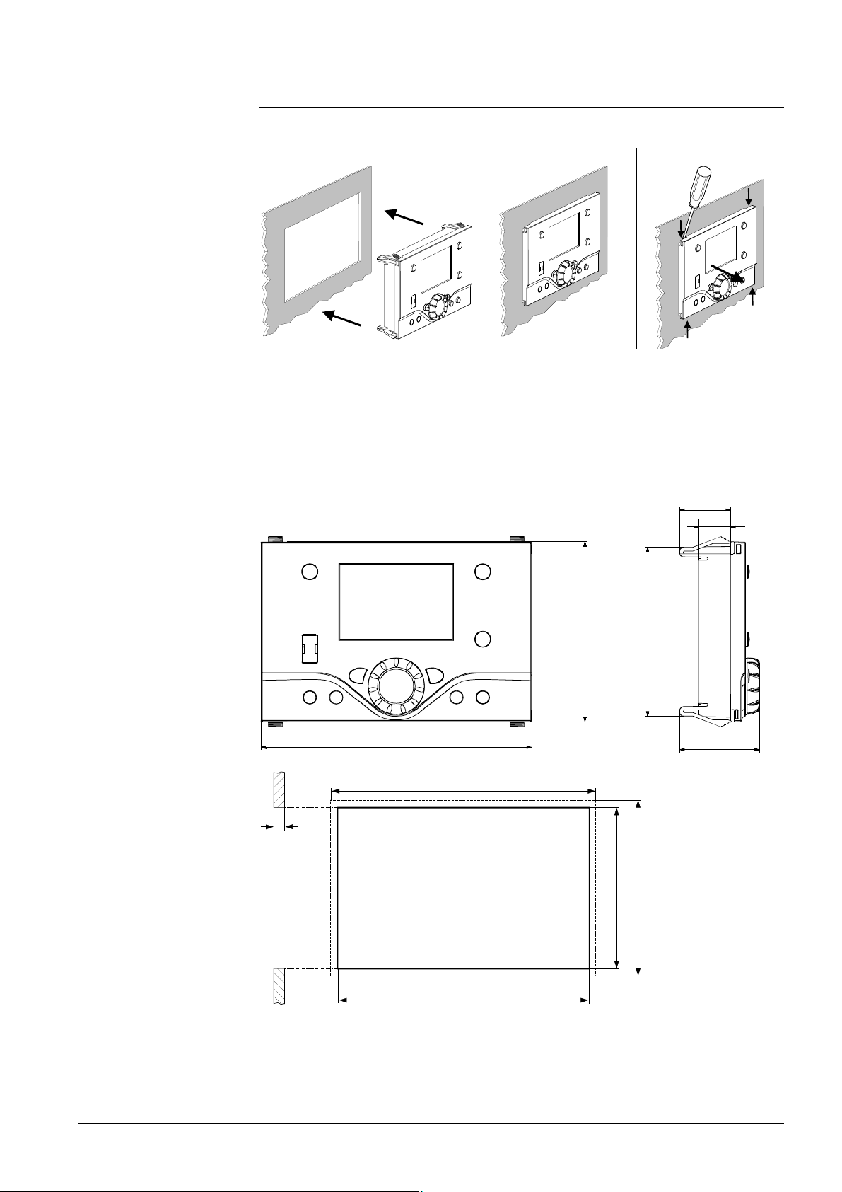
3.2.1 Connection terminals of RVS43.143 .............................................................15
3.2.2 Connection terminals of RVS63.243 .............................................................15
3.2.3 Connection terminals of RVS63.283 .............................................................16
Terminal markings ......................................................................................... 17
3.3 Extension module AVS75.390....................................................................... 19
Dimensions and drilling plan.......................................................................... 19
3.3.1 Connection terminals of AVS75.390.............................................................. 19
Terminal markings ......................................................................................... 20
Assignment of terminals ................................................................................ 20
3.4 Operator unit AVS37.294 ..............................................................................21
Connections................................................................................................... 21
Ground........................................................................................................... 21
3.5 Operator unit AVS37.390 ..............................................................................22
Connections................................................................................................... 22
Dimensions.................................................................................................... 22
3.6 Room unit QAA55… ...................................................................................... 23
Engineering ...................................................................................................23
Mounting method........................................................................................... 23
Connections................................................................................................... 23
Dimensions and drilling plan.......................................................................... 23
3.7 Room unit QAA75… ...................................................................................... 24
Engineering ...................................................................................................24
Mounting method........................................................................................... 24
Connections................................................................................................... 24
Dimensions and drilling plan.......................................................................... 25
3.8 Wireless components .................................................................................... 26
3.8.1 Radio module AVS71.390 ............................................................................. 26
Engineering ...................................................................................................26
Mounting method........................................................................................... 26
Terminals....................................................................................................... 26
Radio connection........................................................................................... 26
Dimensions and drilling plan.......................................................................... 26

4/180
Siemens Schweiz AG User Manual CE1U2354en
HVAC Products 23. August 2007
3.8.2 Room unit QAA78.610 ...................................................................................27
Engineering....................................................................................................27
Mounting with base........................................................................................27
Connection / power supply.............................................................................28
Radio connection ...........................................................................................28
Dimensions and drilling plan ..........................................................................29
3.8.3 Wireless outside sensor AVS13.399..............................................................30
Mounting method ...........................................................................................30
Radio connection ...........................................................................................31
Dimensions and drilling plan ..........................................................................31
3.8.4 Radio repeater AVS14.390 ............................................................................32
Mounting method ...........................................................................................32
Connections ...................................................................................................32
Radio connection ...........................................................................................32
Dimensions and drilling plan ..........................................................................32
3.8.5 Checking the wireless components ...............................................................33
3.9 Power supply AVS16.290 ..............................................................................33
Mounting notes ..............................................................................................33
Connections ...................................................................................................33
4 Commissioning ..............................................................................................35
4.1 Basic units......................................................................................................35
5 Handling.........................................................................................................36
5.1 QAA75.. / QAA78… / AVS37.. .......................................................................36
5.1.1 Operation .......................................................................................................36
Operating elements........................................................................................36
Display options...............................................................................................37
Selection of space heating mode...................................................................37
Selection of cooling mode..............................................................................38
Selecting the DHW heating mode..................................................................38
Adjusting the room temperature setpoint .......................................................38
Presence button.............................................................................................39
Displaying information....................................................................................39
5.1.2 Programming .................................................................................................41
Setting principle .............................................................................................41
Example: “Setting the time of day“.................................................................41
5.1.3 User levels .....................................................................................................42
Setting the structure “End user“ .....................................................................43
Setting the structure ”Heating engineer“ ........................................................43
5.1.4 Overview of settings.......................................................................................44
5.2 AVS37.390.....................................................................................................65
5.2.1 Operation .......................................................................................................65
Operating elements........................................................................................65
Display options...............................................................................................65
Selecting the operating mode ........................................................................65
Adjusting the room temperature setpoint .......................................................66
Adjusting the nominal DHW setpoint .............................................................66
Displaying information....................................................................................66
Setting principle .............................................................................................67
Example: “Setting the time of day“.................................................................67

5/180
Siemens Schweiz AG User Manual CE1U2354en
HVAC Products 23. August 2007
5.2.2 User levels..................................................................................................... 68
5.2.3 Overview of settings ...................................................................................... 69
5.3 QAA55... ........................................................................................................ 70
5.3.1 Operation....................................................................................................... 70
Operating elements ....................................................................................... 70
Display options .............................................................................................. 70
Selection of space heating mode ..................................................................70
Adjusting the room temperature setpoint....................................................... 71
Presence button ............................................................................................71
5.3.2 Programming ................................................................................................. 72
6 The settings in detail...................................................................................... 73
6.1 Time of day and date..................................................................................... 73
6.2 Operator unit.................................................................................................. 73
Operation and display.................................................................................... 73
Heating circuit assignment ............................................................................75
Room sensor ................................................................................................. 75
Device data.................................................................................................... 75
6.3 Radio ............................................................................................................. 76
Binding........................................................................................................... 76
List of wireless devices.................................................................................. 76
6.4 Time programs ..............................................................................................76
Switching points............................................................................................. 77
Standard program.......................................................................................... 77
6.5 Holidays......................................................................................................... 77
6.6 Heating circuits .............................................................................................. 77
Operating mode............................................................................................. 77
Setpoints........................................................................................................ 78
Heating curve ................................................................................................78
ECO functions ...............................................................................................79
Flow temperature setpoint limits.................................................................... 80
Room influence.............................................................................................. 81
Room temp limitation..................................................................................... 82
Boost heating................................................................................................. 82
Quick setback ................................................................................................ 83
Optimum start / stop control ..........................................................................84
Raising the reduced setpoint ......................................................................... 84
Overtemp prot pump circuit ........................................................................... 85
Mixing valve control ....................................................................................... 85
Floor curing function ...................................................................................... 86
Excess heat draw .......................................................................................... 87
Buffer storage tank / primary controller .........................................................87
Speed-controlled pump .................................................................................87
Remote control .............................................................................................. 87
6.7 Cooling circuit ................................................................................................ 88
Operating mode............................................................................................. 88
Setpoints........................................................................................................ 88
Release .........................................................................................................88
Cooling curve................................................................................................. 89
ECO............................................................................................................... 89
Summer compensation.................................................................................. 89

6/180
Siemens Schweiz AG User Manual CE1U2354en
HVAC Products 23. August 2007
Flow temperature setpoint limits ....................................................................90
Room influence ..............................................................................................91
Room temp limitation .....................................................................................91
Mixing valve control .......................................................................................92
Dewpoint monitoring ......................................................................................93
Buffer storage tank / primary controller..........................................................94
Remote control...............................................................................................94
6.8 DHW ..............................................................................................................95
Setpoints ........................................................................................................95
Priority............................................................................................................95
Legionella function .........................................................................................95
Circulating pump ............................................................................................96
6.9 H.. pumps.......................................................................................................96
H.. pumps.......................................................................................................96
6.10 Swimming pool...............................................................................................97
Setpoints ........................................................................................................97
Priority............................................................................................................97
Plant hydraulics..............................................................................................98
6.11 Primary controller / system pump ..................................................................98
Primary controller / system pump ..................................................................98
6.12 Boiler..............................................................................................................98
Operating mode .............................................................................................98
Setpoints ........................................................................................................98
Minimum limitation of the return temperature ................................................99
Output data ....................................................................................................99
2 x 1 cascade...............................................................................................100
6.13 Cascade.......................................................................................................100
Control .........................................................................................................100
Boiler sequence ...........................................................................................100
Minimum limitation of the return temperature ..............................................101
6.14 Solar.............................................................................................................102
Charging controller (dT) ...............................................................................102
Priority..........................................................................................................102
Start function................................................................................................103
Frost protection for the collector ..................................................................104
Overtemperature protection for the collector ...............................................104
Medium’s evaporation temperature .............................................................104
Speed control...............................................................................................104
Yield measurement ......................................................................................105
6.15 Solid fuel boiler ............................................................................................105
Operating mode ...........................................................................................105
Setpoints ......................................................................................................105
Boiler / burner control...................................................................................105
6.16 Buffer storage tank.......................................................................................106
Automatic locks............................................................................................106
Stratification protection ................................................................................107
Overtemperature protection .........................................................................108
Recooling .....................................................................................................108
Plant hydraulics............................................................................................108
Return diversion...........................................................................................108
Partial charging ............................................................................................109
Cooling.........................................................................................................110

7/180
Siemens Schweiz AG User Manual CE1U2354en
HVAC Products 23. August 2007
6.17 DHW storage tank ....................................................................................... 110
Charging control .......................................................................................... 110
Overtemperature protection......................................................................... 110
Recooling..................................................................................................... 110
Electric immersion heater ............................................................................ 111
Plant hydraulics ........................................................................................... 112
Speed-controlled pump ...............................................................................112
6.18 Instantaneous DHW heater ......................................................................... 112
Setpoints...................................................................................................... 112
Mixing valve control ..................................................................................... 113
6.19 Configuration ............................................................................................... 113
Heating circuits ............................................................................................ 113
DHW sensor B3........................................................................................... 114
DHW control element Q3............................................................................. 114
Separate DHW circuit .................................................................................. 115
Boiler ...........................................................................................................115
Solar ............................................................................................................ 118
Output relay QX........................................................................................... 119
Input sensor BX ........................................................................................... 122
Input H1 for RVS43.. ...................................................................................123
Input H.. for RVS63.. ..................................................................................128
Input EX2..................................................................................................... 131
Mixing valve groups basic unit..................................................................... 132
Extension module ........................................................................................ 133
QX extension module .................................................................................. 134
BX extension module................................................................................... 135
H2 extension module................................................................................... 135
10V output UX ............................................................................................. 136
Types of sensor/readjustment ..................................................................... 136
Building and room model............................................................................. 137
Frost protection for the plant........................................................................ 137
External requirements .................................................................................137
Sensor state ................................................................................................138
Parameter reset........................................................................................... 138
Plant diagram ..............................................................................................138
Device data.................................................................................................. 141
6.20 LPB.............................................................................................................. 141
Address / power supply ............................................................................... 141
Central functions.......................................................................................... 141
Clock............................................................................................................ 143
6.21 Faults........................................................................................................... 143
6.22 Maintenance/special mode.......................................................................... 144
Maintenance functions................................................................................. 144
Chimney sweep ........................................................................................... 144
Manual operation......................................................................................... 145
Simulations .................................................................................................. 146
Telephone customer service .......................................................................146
6.23 Input / output test......................................................................................... 146
6.24 State ............................................................................................................ 147
Messages .................................................................................................... 147
6.25 Diagnostics, heat generation ....................................................................... 150
6.26 Diagnostics, consumers ..............................................................................150

8/180
Siemens Schweiz AG User Manual CE1U2354en
HVAC Products 23. August 2007
6.27 List of displays .............................................................................................151
6.27.1 Error code ....................................................................................................151
6.27.2 Maintenance code........................................................................................152
6.27.3 Special operation code ................................................................................152
7 Plant diagrams .............................................................................................153
7.1 Basic diagrams ............................................................................................153
7.1.1 Basic diagram RVS43.143...........................................................................153
7.1.2 Basic diagram RVS63.243...........................................................................154
7.1.3 Basic diagram RVS63.283...........................................................................155
7.2 Versions of heat sources .............................................................................156
7.3 Extra functions in general ............................................................................157
Solar.............................................................................................................157
Boiler............................................................................................................159
DHW storage tank (DHW)............................................................................160
Heating/cooling circuit..................................................................................161
Heat converter .............................................................................................162
Swimming pool.............................................................................................162
Pressureless header ....................................................................................162
Extra functions .............................................................................................162
7.4 Additional funct. with mix. valve group or extension module AVS75.390 ....163
Legend mains voltage..................................................................................166
Legend low-voltage......................................................................................167
8 Technical data..............................................................................................168
8.1 Basic units RVS…........................................................................................168
8.2 Extension module AVS75.390 .....................................................................169
8.3 Operator unit and room units AVS37... / QAA7x… / QAA55.. .....................170
8.4 Power supply AVS16.290 ............................................................................171
8.5 Radio module AVS71.390............................................................................171
8.6 Wireless outside sensor AVS13.399............................................................172
8.7 Radio repeater AVS14.390 ..........................................................................173
8.8 Sensor characteristics..................................................................................174
8.8.1 NTC 1 k........................................................................................................174
8.8.2 NTC 10 k......................................................................................................175
8.8.3 PT1000 ........................................................................................................175
9 Revision history............................................................................................179
9/180
Siemens Schweiz AG User Manual CE1U2354en
HVAC Products Type summary 23. August 2007
1 Summary
The present User Manual describes the products listed in the following table and covers
handling and configuration of the controls for readers ranging from end users to heating
engineers.
Type reference
(ASN)
Series Name
RVS43.143 B Basic unit boiler
RVS63.243 B Basic unit boiler
RVS63.283 B Basic unit boiler
AVS75.390 B Extension module
AVS37.294 B operator unit
AVS37.390 A Operator unit basic
QAA75.610 B Room unit, wired
QAA75.611 B Room unit with backlight, wired
QAA78.610 B Room unit, wireless
QAA55.110 A Room unit basic
AVS16.290 A Power section
AVS71.390 A Radio module
AVS14.390 A Radio repeater
AVS13.399 A Wireless outside sensor
The following products are described in separate pieces of documentation:
QAC34 Outside sensor NTC 1 kΩ
QAD36 Strap-on temperature sensor NTC 10 kΩ
QAZ36 Immersion temperature sensor NTC 10 kΩ
10/180
Siemens Schweiz AG User Manual CE1U2354en
HVAC Products Type summary 23. August 2007
1.1 Type summary
1.1.1 Topology
Remote
Service Tool
Mobile, SMS, Pager, Fax,
WEB,
Telephone
Network
Telephone
SMS
OCI611
OCI700
ACS700
BSB :
Boiler System Bus
Room
Unit
Service Unit
(RU)
HMI
HMI
(RU)
wired
wired
wired
Basic Unit
RVSxx
Extension
mod. AVS75…
(max. 2)
BSB-W
LPB : Local Process Bus
Basic Unit
RVS...
LPB
Remote
Service Tool
Mobile, SMS, Pager, Fax,
WEB,
Telephone
Network
Telephone
SMS
OCI611
OCI700
RF
module
ACS700
BSB :
Boiler System Bus
Room
Unit
RF
Repeater
RF
Toutside
BSB-RF
Service Unit
(RU)
HMI
(RU)
wireless
wireless
wireless
Basic Unit
RVSxx
Extension
mod. AVS75…
(max. 2)
BSB-W
LPB : Local Process Bus
Basic Unit
RVS...
LPB
Wired
Wireless

11/180
Siemens Schweiz AG User Manual CE1U2354en
HVAC Products Type summary 23. August 2007
Operating options
Wired Wireless
B
A
B
A
C
E1
D
B
A
2359Z66
T
C
D
F
B
A
2359Z67
T
E1
EB
A
B
A
E
A Basic unit RVS…
B Power section AVS16…
C Room unit QAA75… / 78… / QAA55..
D Outside sensor AVS13…
E Operator unit AVS37.294 (clear-text)
E1 Operator unit AVS37.390 (basic)
F Radio module AVS71…
Operation with room
unit
Operation with “basic”
operator unit
(optionally with additional
room unit)
Operation with “clear-text”
operator unit
(optionally with additional room
unit)

12/180
Siemens Schweiz AG User Manual CE1U2354en
HVAC Products Product liability 23. August 2007
2 Safety notes
2.1 Product liability
• The products may only be used in building services plant and applications as
described above
• When using the products, all requirements specified in the chapters on "Handling"
and "Technical data" must be satisfied
• Local regulations (for installation, etc.) must be complied with
• Do not open the units. If not observed, warranty becomes void.

13/180
Siemens Schweiz AG User Manual CE1U2354en
HVAC Products Regulations 23. August 2007
3 Mounting and installation
3.1 Regulations
Electrical installation
• Prior to installing the controller, the power supply must be turned off
• The connections for mains and low-voltage are separated
• The wiring must be made in compliance with the requirements of safety class II. This
means that sensor and mains cables may not be run in the same duct
3.2 Basic units RVS…
Engineering
• Air circulation around the controller must be ensured, allowing the unit to emit the
heat produced by it.
A clearance of at least 10 mm must be provided for the controller's cooling slots
which are situated a the top and bottom of the housing.
The space should not be accessible and no objects should be placed there. If the
controller is enclosed in another (insulating) casing, a clearance of up to 100 mm
must be observed around the cooling slots
• The controller is designed conforming to the directives for safety class II mounted in
compliance with these regulations.
• Power to the controller may only be supplied when completely fitted. If this is not
observed, there is a risk of electric shock hazard near the terminals and through the
cooling slots.
• The controller may not be exposed to dripping water.
• Permissible ambient temperature when mounted and when ready to
operate: 0..50°C.
• Power cables must be clearly segregated from low-voltage cables (sensors)
observing a distance of at least 100 mm
• Boiler
• Control panel
• Housing for wall mounting
Mounting location
14/180
Siemens Schweiz AG User Manual CE1U2354en
HVAC Products Basic units RVS… 23. August 2007
2359Z10
x
Mounting method
Screwed
On DIN rail
2359Z09
A1
A2
B1
B2
2359Z11
A: Mounting / B: Removal
Note:
To mount the controller on a DIN rail, a mounting clip
is required!
Dimensions and drilling plan
L
B
L1
B1
2358M01
L B H L1 B1
RVS63…
281 121 52 270 110
RVS43…
181 121 52 170 110
Dimension X:
Connectors with tongues minimum 70 mm
Connector without tongues minimum 60 mm
Total height required
Dimensions in mm
15/180
Siemens Schweiz AG User Manual CE1U2354en
HVAC Products Basic units RVS… 23. August 2007
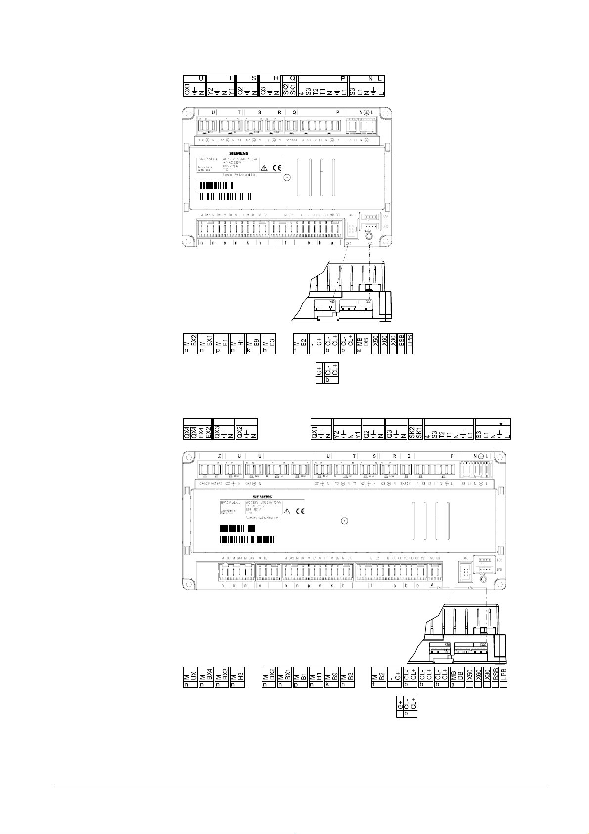
3.2.1 Connection terminals of RVS43.143
2354Z08
050110A
000020RVS43.143/109
1PRVS13.143/109
S05011000002 0
3.2.2 Connection terminals of RVS63.243
Z
U U
T
S R Q
P LN
U
2354Z06
061107B
000020RVS63.243/10 9
1PRVS63.243/109
S061107000020
16/180
Siemens Schweiz AG User Manual CE1U2354en
HVAC Products Basic units RVS… 23. August 2007
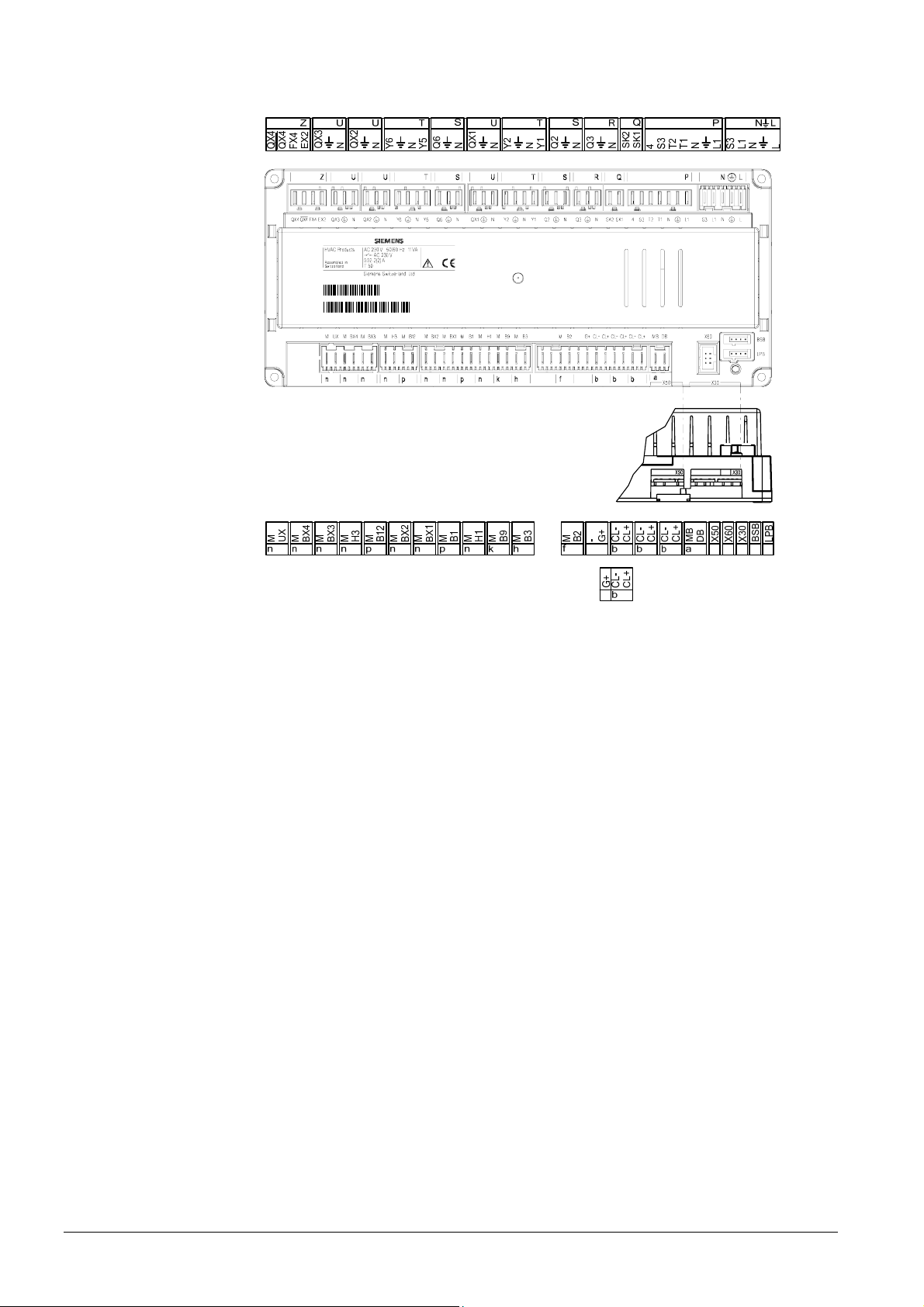
3.2.3 Connection terminals of RVS63.283
2354Z07
061107B
000020RVS63.283/10 9
1PRVS63.283/109
S061107000020
17/180
Siemens Schweiz AG User Manual CE1U2354en
HVAC Products Basic units RVS… 23. August 2007
Terminal markings
Use Slot Connector type
L Live AC 230 V basic unit N L AGP4S.05A/109
Protective earth
N Neutral conductor
L1 Live AC 230 V burner
S3 Output burner fault
L1 Phase burner P AGP8S.07A/109
Protective earth
N Neutral conductor
T1 Phase 1st burner stage
T2 1st burner stage on
S3 Input burner fault
4 Input 1st burner stage operating hours
SK1 Safety loop Q AGP8S.02E/109
SK2 Safety loop
N Neutral conductor R AGP8S.03A/109
Protective earth
Q3 DHW charging pump / diverting valve
N Neutral conductor S AGP8S.03B/109
Protective earth
Q2
1st heating circuit pump
Y1
1st heating circuit mixing valve opening
T AGP8S.04B/109
N Neutral conductor
Protective earth
Y2 1st heating circuit mixing valve closing
N Neutral conductor U AGP8S.03C/109
Protective earth
QX1 Multifunctional output 1
N Neutral conductor S AGP8S.03B/109
Protective earth
Q6 2nd heating circuit pump
Y5 2nd heating circuit mixing valve opening T AGP8S.04B/109
N Neutral conductor
Protective earth
Y6 1st heating circuit mixing valve closing
N Neutral conductor U AGP8S.03C/109
Protective earth
QX2 Multifunctional output 2
N Neutral conductor U AGP8S.03C/109
Protective earth
QX3 Multifunctional output 3
EX2 Multifunctional input Z AGP8S.04C/109
FX4
(T6)
Multifunctional output 4
(phase 2nd burner stage)
QX4
(T7)
Multifunctional output 4 off
(2nd burner stage off)
QX4
(T8)
Multifunctional output 4 on
(2nd burner stage on)
Mains voltage
18/180
Siemens Schweiz AG User Manual CE1U2354en
HVAC Products Basic units RVS… 23. August 2007
Use Slot Connector type
BSB Service tool OCI700 - -
LPB Service tool OCI700 - -
X60 Radio module AVS71.390 - -
X50 Extension module AVS75.390 -
AVS82.490/109
X30 Operator unit / boiler control panel -
AVS82.491/109
DB LPB data
AGP4S.02H/109
MB LPB ground
CL+ BSB data
AGP4S.02A/109
CL- BSB ground b
CL+ Room unit 2 data
AGP4S.02A/109
CL- Room unit 2 ground b
CL+ Room unit 1 data
AGP4S.02A/109
CL- Room unit 1 ground b AGP4S.03D/109
G+ Room unit power supply 12 V
B2 Boiler sensor
AGP4S.02B/109
M Ground f
B3 DHW sensor top
AGP4S.02C/109
M Ground h
B9 Outside sensor
AGP4S.02D/109
M Ground k
H1 Digital / DC 0...10 V input
AGP4S.02F/109
M Ground n
B1 Flow temperature sensor HK1
AGP4S.02G/109
M Ground p
BX1 Multifunctional sensor input 1 AGP4S.02F/109
M Ground n
BX2 Multifunctional sensor input 2 AGP4S.02F/109
M Ground n
B12 Flow temperature sensor HK2
AGP4S.02G/109
M Ground p
H3 Digital / DC 0...10 V input
AGP4S.02F/109
M Ground n
BX3 Multifunctional sensor input 3
AGP4S.02F/109
M Ground n
BX4 Multifunctional sensor input 4
AGP4S.02F/109
M Ground n
UX DC 0…10 V output n AGP4S.02F/109
M Ground
Low voltage
19/180
Siemens Schweiz AG User Manual CE1U2354en
HVAC Products Extension module AVS75.390 23. August 2007
3.3 Extension module AVS75.390
For planning, mounting location and mounting method, refer to the information given for
the basic modules.
Dimensions and drilling plan
L
B
L1
B1
2358M01
L B H L1 B1
AVS75.390
108.7 120.9 51.7 98 110
The AVS75.390 extension module is connected to terminal
X50 of the basic unit using
the
AVS83.490/109 connecting cable. The connectors are coded.
3.3.1 Connection terminals of AVS75.390
050110A
000020
AVS75.390/109
1PAVS75.390/109
S050110000020
2359Z49
Connections
1
12
= Module 1
2
1
2
= Module 2
Dimensions in mm
20/180
Siemens Schweiz AG User Manual CE1U2354en
HVAC Products Extension module AVS75.390 23. August 2007
Terminal markings
Use Slot Connector type
L Live AC 230 V basic unit N L AGP4S.03E/109
Protective earth
N Neutral conductor
QX21 Assignment according to function T AGP8S.04B/109
N Neutral conductor
Protective earth
QX22 Assignment according to function
N Neutral conductor S AGP8S.03B/109
Protective earth
QX23 Assignment according to function
Use Space Connector type
X30 Operator unit / boiler control panel -
AVS82.491/109
X50 Basic unit
AVS82.490/109
BX21 Assignment according to function AGP4S.02F/109
M Ground n
BX22 Assignment according to function AGP4S.02F/109
M Ground n
H2 Digital / DC 0...10 V input AGP4S.02F/109
M Ground n
Assignment of terminals
The two following parameters define the usage of the respective module:
• Function extension module 1 (operating line 6020)
• Function extension module 2 (operating line 6021)
.
Mains voltage
Low voltage
21/180
Siemens Schweiz AG User Manual CE1U2354en
HVAC Products Operator unit AVS37.294 23. August 2007
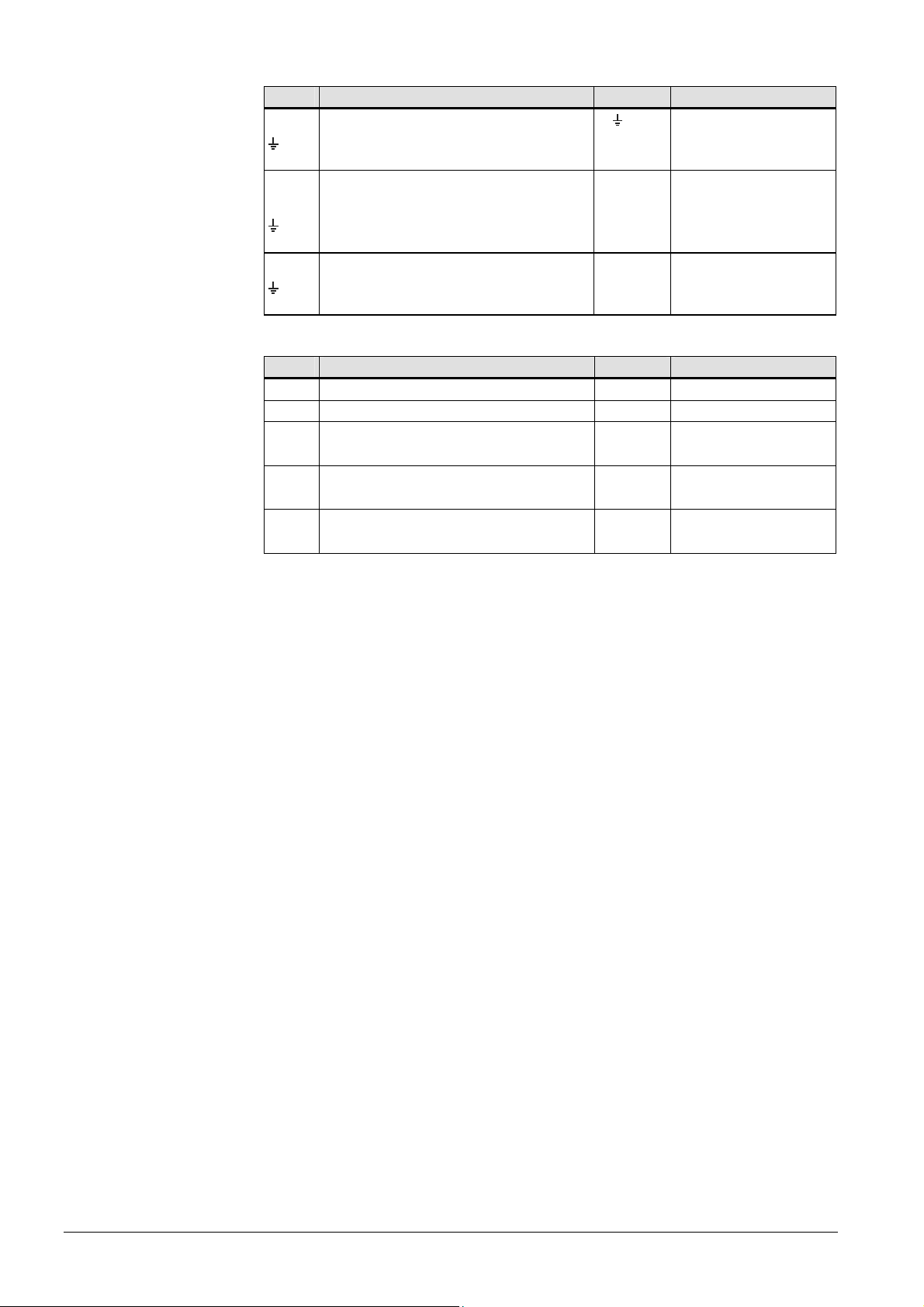
3.4 Operator unit AVS37.294
Mounting method
Installation
Removal
2358Z30
2358Z31
2358Z32
Connections
The AVS37.294 operator unit must be connected to terminal X30 of the basic unit using
the AVS82.491/109 connecting cable. The connectors are coded.
Ground
(144)
0.5...3.0
92
+0.8
0
138
+1
0
2358M05
(96)
Panel cutout
2358M03
144
96
90
27
42.4
17
22/180
Siemens Schweiz AG User Manual CE1U2354en
HVAC Products Operator unit AVS37.390 23. August 2007
3.5 Operator unit AVS37.390
Connections
The AVS37.390 operator unit must be connected to terminal X30 of the basic unit using
the AVS82.491/109 connecting cable. The connectors are coded.
Dimensions
2354M01
13
0,5
A
A Control panel, front
23/180
Siemens Schweiz AG User Manual CE1U2354en
HVAC Products Room unit QAA55… 23. August 2007
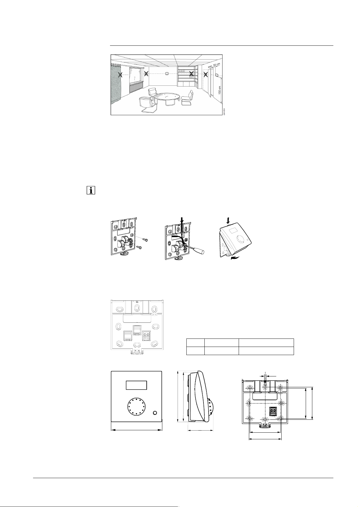
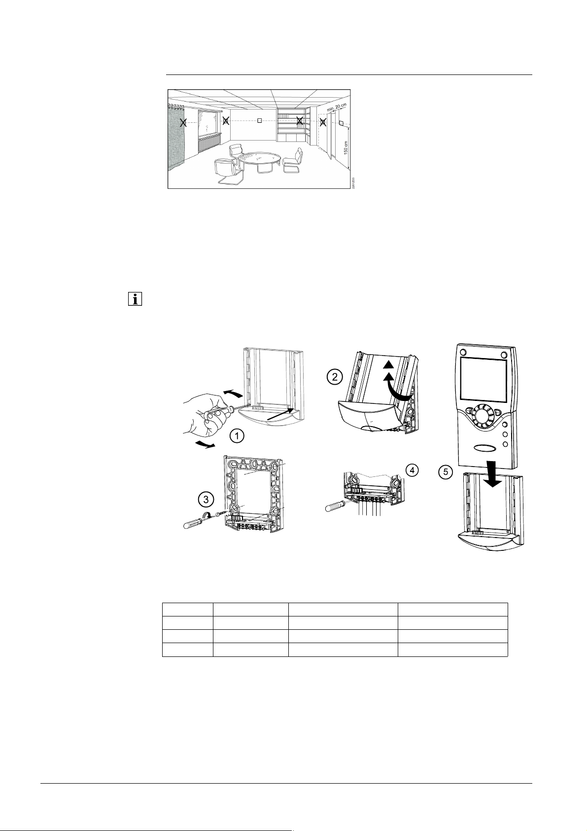
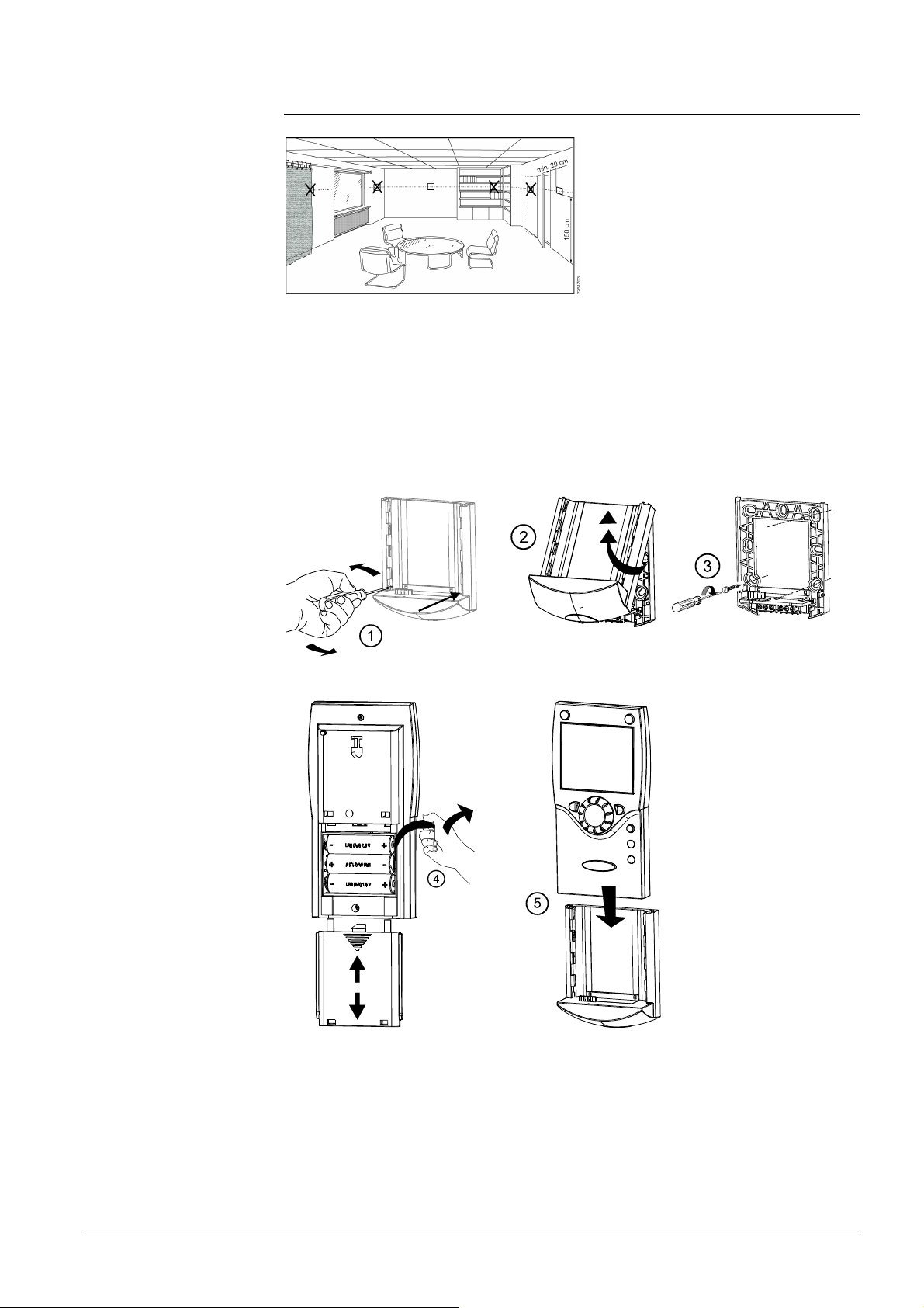
3.6 Room unit QAA55…
Engineering
@
The room unit should be located in the main living room while giving consideration to
the following points:
• The place of installation should be chosen so that the sensor can capture the room
temperature as accurately as possible without getting adversely affected by direct
solar radiation or other heat or refrigeration sources (about 1.5 meters above the floor)
• In the case of wall mounting, there must be sufficient clearance above the unit,
enabling it to be fitted and removed
When the unit is removed from its base, power is cut off so that the unit is out of
operation.
Mounting method
2284Z33a
2284Z34a
• The controller must not be exposed to dripping water
Connections
1
34
562
2284Z40
1 CL+ BSB data
2 CL- BSB ground
Dimensions and drilling plan
2282M02
96
9
6
9
1
4
7
12
2359Z27
4,2
56
60
56
60
24/180
Siemens Schweiz AG User Manual CE1U2354en
HVAC Products Room unit QAA75… 23. August 2007
3.7 Room unit QAA75…
Engineering
@
The room unit should be located in the main living room while giving consideration to
the following points:
• The place of installation should be chosen so that the sensor can capture the room
temperature as accurately as possible without getting adversely affected by direct
solar radiation or other heat or refrigeration sources (about 1.5 meters above the floor)
• In the case of wall mounting, there must be sufficient clearance above the unit,
enabling it to be fitted and removed
When the unit is removed from its base, power is cut off so that the unit is out of
operation.
Mounting method
Connections
Terminal Name QAA75.610 QAA75.611
1 CL+ BSB data BSB data
2 CL- BSB ground BSB ground
3 G+ Reserved Power supply DC 12 V
2359Z20
2359Z26
2359Z24
2359Z21
2359Z25
25/180
Siemens Schweiz AG User Manual CE1U2354en
HVAC Products Room unit QAA75… 23. August 2007
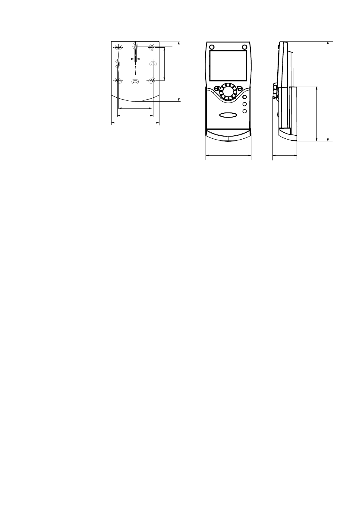
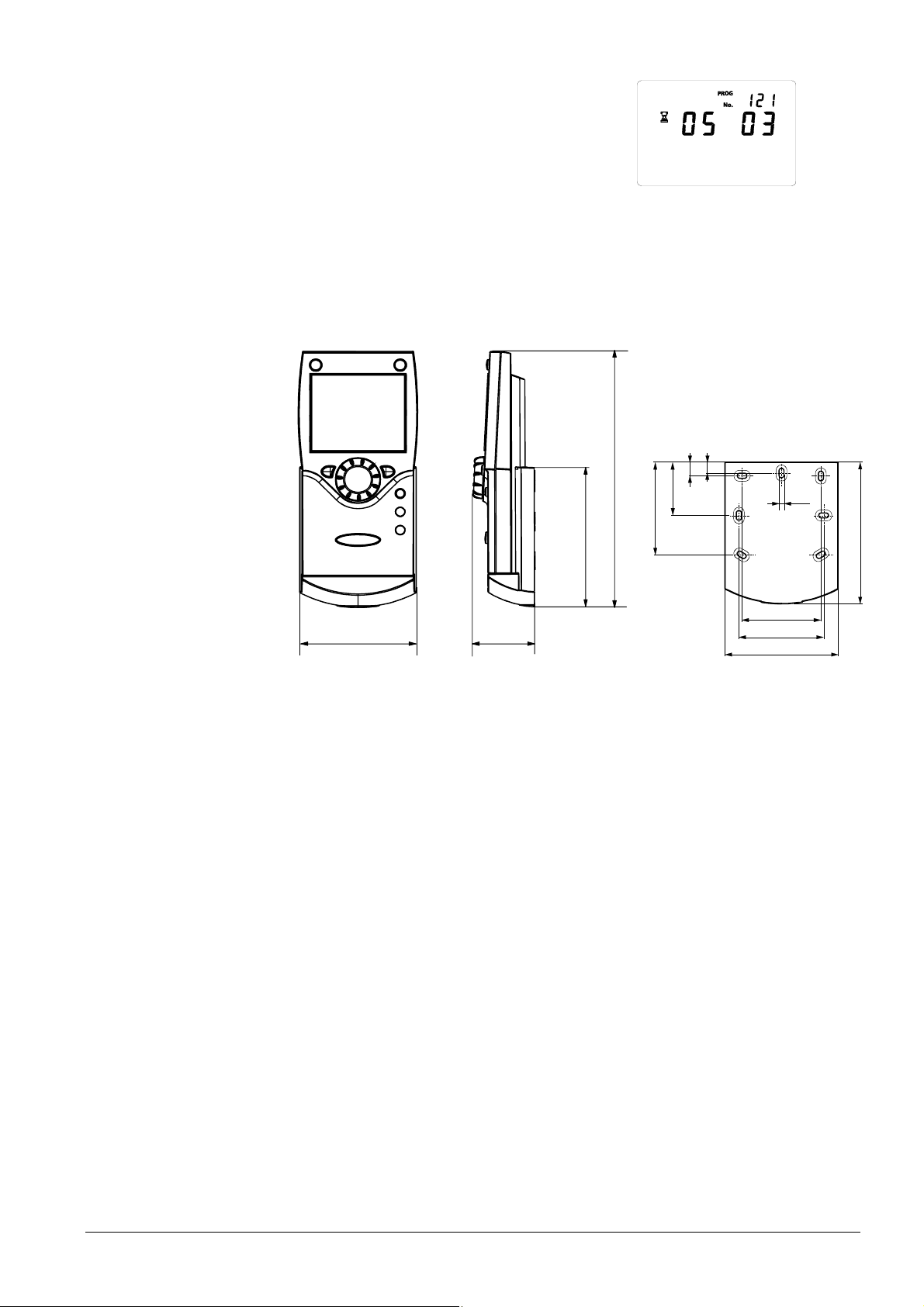
Dimensions and drilling plan
2359Z50
4,2
56
60
56
60
100
80
42
185
2359Z12
100
82
26/180
Siemens Schweiz AG User Manual CE1U2354en
HVAC Products Wireless components 23. August 2007
3.8 Wireless components
The wireless components should be located such that transmission will be as
interference-free as possible. The following criteria must be observed:
• Not in the vicinity of electrical cables, strong magnetic fields or equipment like PCs,
TV sets, microwave ovens, etc.
• Not near larger metal structures or constructional elements with fine metal meshes
such as special glass or special concrete
• The distance to the transmitter should not exceed 30 meters or 2 floors
3.8.1 Radio module AVS71.390
The radio module extends the product range by introducing wireless communication.
With this type of device, the system components, such as room units, transmit data with
no need for laying cables.
Engineering
Do not install the radio module inside metal casings (e.g. inside a boiler).
Mounting method
2359Z23
Terminals
The prefabricated cable is to be connected to terminal X60 of the controller.
Prior to connecting the module, the basic unit must be disconnected from power!
Radio connection
Establishment of the wireless connection is described in the following sections which
cover the relevant radio-controlled units.
Dimensions and drilling plan
43
2354Z11
2359Z57
A
B
LED
Button
27/180
Siemens Schweiz AG User Manual CE1U2354en
HVAC Products Wireless components 23. August 2007
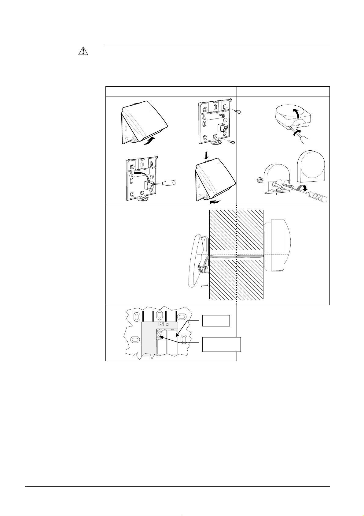
3.8.2 Room unit QAA78.610
Engineering
@
The room unit should be located in the main living room while giving consideration to
the following points:
• The place of installation should be chosen so that the sensor can capture the room
temperature as accurately as possible without getting adversely affected by direct
solar radiation or other heat or refrigeration sources (about 1.5 meters above the floor)
• In the case of wall mounting, there must be sufficient clearance above the unit,
enabling it to be fitted and removed
Mounting with base
2359Z20
2359Z26
2359Z22
2359Z21
2359Z25
28/180
Siemens Schweiz AG User Manual CE1U2354en
HVAC Products Wireless components 23. August 2007
2359Z61
Connection / power supply
The room unit is powered by 3 pieces 1.5 V alkaline batteries type AA (LR06).
Radio connection
Make the radio connection in the vicinity of the radio module prior to mounting so that
all system are within easy reach.
Prerequisite for the radio connection is that all components receive power, which
means that the radio module must be correctly connected to the basic unit and the
batteries must be correctly installed in the room unit.
1. Press the button on the installed radio module for at least 8 seconds until the LED
on the radio module starts flashing at high frequency.
2. Press OK on the room unit to switch to programming.
3. Press the info button for at least 3 seconds and select operating level
“Commissioning“ with the setting knob. Then, press OK.
4. Select operating page “Operator unit“ and press OK.
5. Select operating line “Used as“ (operating line 40) and make the appropriate
selection. Then, press OK.
6. Select operating page “Radio“ and press OK.
7. Select setting line “Binding“ (line 120). Then, press OK.
8. Set the setting knob to “YES“ and press OK. Connection establishment is started.
9. The display shows the progress of connection establishment in %. This process can
take 2 to 120 seconds.
10. The connection is established when “Device ready” appears and the LED on the
radio module extinguishes
The test is made to check the quality of the radio link.
• The test can be aborted by pressing the ESC button.
• While the radio link can be opened on the controller, the test should be made at the
location where the room unit will be installed
On the room unit, as described above (points 2 through 4), select operating page
“Radio“ and activate the test mode on setting line “Test mode“ (line 121).
Mounting without base
Establishing the link
Testing
29/180
Siemens Schweiz AG User Manual CE1U2354en
HVAC Products Wireless components 23. August 2007
Example of a display during the test:
The digits on the left shows telegrams that have
been sent, the digits on the right telegrams that
have been received. The test will be ended
after 24 telegrams. The test is considered
successful when at least 50 % of the telegrams
sent have been received.
If the test was not successful, some other mounting location is to be selected or the
AVS14.390 radio repeater can be used.
Dimensions and drilling plan
42
185
2359Z12
100
82
2359Z50
4,2
9
56
60
100
80
11
39
67
Bedieneinheit
Testmode
30/180
Siemens Schweiz AG User Manual CE1U2354en
HVAC Products Wireless components 23. August 2007
2359Z53
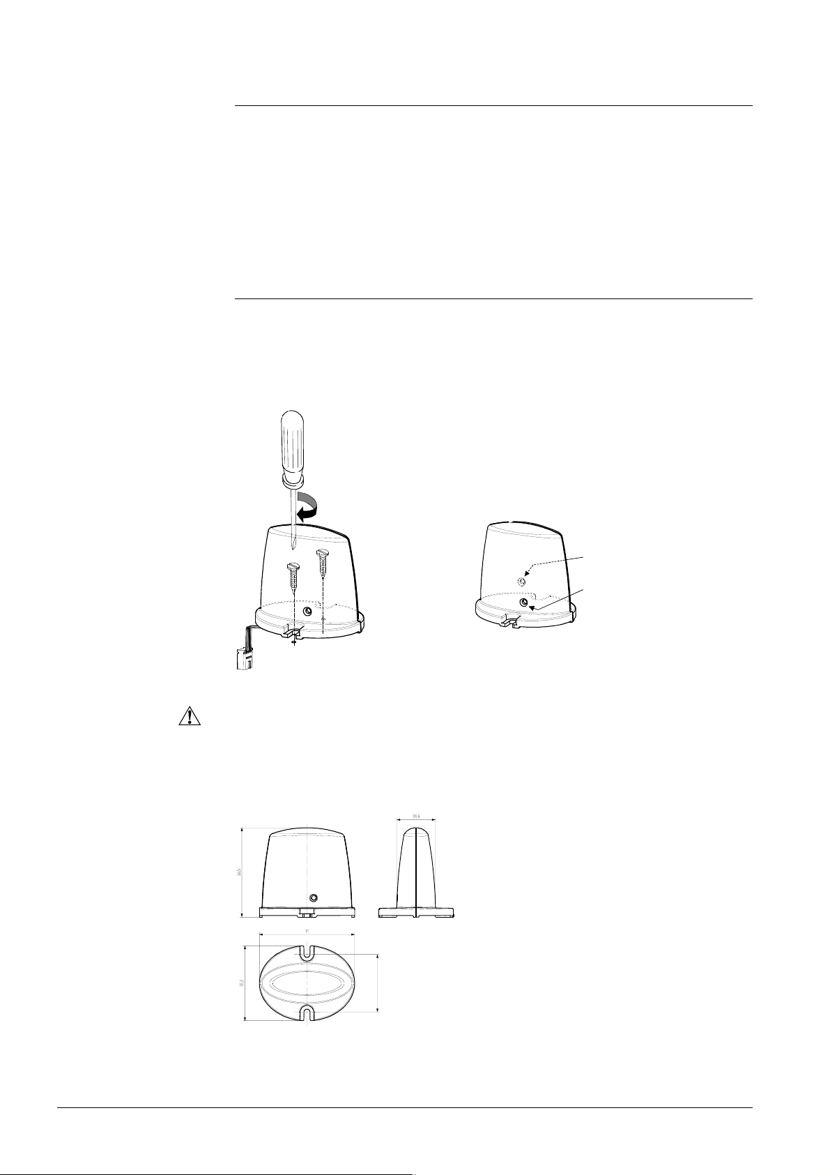
3.8.3 Wireless outside sensor AVS13.399
• The radio transmitter must be installed inside the building.
• The radio transmitter’s mounting location should be chosen such that batteries
can be easily changed.
Mounting method
RF transmitter
Outside sensor
The outside sensor is to be connected to the radio transmitter via a 2-core cable, the
connections are interchangeable.
The room unit is powered by two 1.5 V alkaline batteries type AAA (LR03).
Connections
2359Z54
2359Z30
2359Z33
2359Z31
2359Z55
AAA
AAA
Battery transit
tab
Battery
2359Z32
2359Z59
 Loading...