


420
Table of contents
 Loading...
MICROMASTER 420
0.12 kW - 11 kW
Operating Instructions Issue 07/04
User Documentation
6SE6400-5AA00-0BP0
MICROMASTER 420 Documentation
Getting Started Guide
Is for quick commissioning with SDP and BOP.
Operating Instructions
Gives information about features of the MICROMASTER
420, Installation, Commissioning, Control modes, System
Parameter structure, Troubleshooting, Specifications and
available options of the MICROMASTER 420.
Parameter List
The Parameter List contains the description of all
Parameters structured in functional order and a detailed
description. The Parameter list also includes a series of
function plans.
Catalogues
In the catalogue you will find all the necessary information
to select an appropriate inverter, as well as filters, chokes,
operator panels and communication options.

MICROMASTER 420
0.12 kW - 11 kW
Operating Instructions
User Documentation
Overview
Installation
Commissioning
Troubleshooting
MICROMASTER 420
specifications
Options
1
2
3
4
5
6
Valid for Release Issue 07/04
Inverter Type Control Version
MICROMASTER 420 V1.1
0.12 kW - 11 kW
Electro-magnetic
compatibility (EMC)
Appendices
Index
7
A
B
C
D
E
F
Issue 07/04

Further information is available on the Internet under:
http://www.siemens.de/micromaster
Approved Siemens Quality for Software and Training
is to DIN ISO 9001, Reg. No. 2160-01
The reproduction, transmission or use of this document,
or its contents is not permitted unless authorized in
writing. Offenders will be liable for damages. All rights
including rights created by patent grant or registration of a
utility model or design are reserved.
© Siemens AG 2001, 2002, 2004. All Rights Reserved.
MICROMASTER® is a registered trademark of Siemens.
Order Number: 6SE6400-5AA00-0BP0
Other functions not described in this document may be
available. However, this fact shall not constitute an
obligation to supply such functions with a new control, or
when servicing.
We have checked that the contents of this document
correspond to the hardware and software described.
There may be discrepancies nevertheless, and no
guarantee can be given that they are completely identical.
The information contained in this document is reviewed
regularly and any necessary changes will be included in
the next edition. We welcome suggestions for
improvement.
Siemens handbooks are printed on chlorine-free paper
that has been produced from managed sustainable
forests. No solvents have been used in the printing or
binding process.
Document subject to change without prior notice.
Siemens-Aktiengesellschaft
MICROMASTER 420 Operating Instructions
4 6SE6400-5AA00-0BP0

Issue 07/04 Foreword
Foreword
User Documentation
WARNING
Before installing and commissioning, you must read the safety instructions and
warnings carefully and all the warning labels attached to the equipment. Make
sure that the warning labels are kept in a legible condition and replace missing or
damaged labels.
Information is also available from:
Regional Contacts
Please get in touch with your contact for Technical Support in your Region for
questions about services, prices and conditions of Technical Support.
Central Technical Support
The competent consulting service for technical issues with a broad range of
requirements-based services around our products and systems.
Europe / Africa
Tel: +49 (0) 180 5050 222
Fax: +49 (0) 180 5050 223
Email: adsupport@siemens.com
America
Tel: +1 423 262 2522
Fax: +1 423 262 2589
Email: simatic.hotline@sea.siemens.com
Asia / Pacific
Tel: +86 1064 757 575
Fax: +86 1064 747 474
Email: adsupport.asia@siemens.com
Online Service & Support
The comprehensive, generally available information system over the Internet, from
product support to service & support to the support tools in the shop.
http://www.siemens.com/automation/service&support
Contact address
Should any questions or problems arise while reading this manual, please contact
the Siemens office concerned using the form provided at the back this manual.
MICROMASTER 420 Operating Instructions
6SE6400-5AA00-0BP0
5
Definitions Issue 07/04
f
y
Definitions and Warnings
DANGER
indicates an imminently hazardous situation which, if not avoided, will result in
death or serious injury.
WARNING
indicates a potentially hazardous situation which, if not avoided, could result in
death or serious injury.
CAUTION
used with the safety alert symbol indicates a potentially hazardous situation which,
if not avoided, may result in minor or moderate injury.
PE
= Ground
CAUTION
used without safety alert symbol indicates a potentially hazardous situation which, i
not avoided, may result in a property damage.
NOTICE
indicates a potential situation which, if not avoided, may result in an undesirable
result or state.
NOTES
For the purpose of this documentation, "Note" indicates important information
relating to the product or highlights part of the documentation for special attention.
Qualified personnel
For the purpose of this Instruction Manual and product labels, a "Qualified person"
is someone who is familiar with the installation, mounting, start-up and operation
of the equipment and the hazards involved. He or she must have the following
qualifications:
1. Trained and authorized to energize, de-energize, clear, ground and tag
circuits and equipment in accordance with established safety procedures.
2. Trained in the proper care and use of protective equipment in accordance with
established safety procedures.
3. Trained in rendering first aid.
♦ PE – Protective Earth uses circuit protective conductors sized for short circuits
where the voltage will not rise in excess of 50 Volts. This connection is normall
used to ground the inverter.
♦
- Is the ground connection where the reference voltage can be the same as
the Earth voltage. This connection is normally used to ground the motor.
Use for intended purpose only
The equipment may be used only for the application stated in the manual and only
in conjunction with devices and components recommended and authorized by
Siemens.
MICROMASTER 420 Operating Instructions
6 6SE6400-5AA00-0BP0

Issue 07/04 Safety Instructions
Safety Instructions
The following Warnings, Cautions and Notes are provided for your safety and as a
means of preventing damage to the product or components in the machines
connected. This section lists Warnings, Cautions and Notes, which apply generally
when handling MICROMASTER 420 Inverters, classified as General, Transport &
Storage, Commissioning, Operation, Repair and Dismantling & Disposal.
Specific Warnings, Cautions and Notes that apply to particular activities are
listed at the beginning of the relevant chapters and are repeated or supplemented
at critical points throughout these chapters.
Please read the information carefully, since it is provided for your personal
safety and will also help prolong the service life of your MICROMASTER 420
Inverter and the equipment you connect to it.
General
WARNING
♦ This equipment contains dangerous voltages and controls potentially
dangerous rotating mechanical parts. Non-compliance with Warnings or
failure to follow the instructions contained in this manual can result in loss of
life, severe personal injury or serious damage to property.
♦ Only suitable qualified personnel should work on this equipment, and only
after becoming familiar with all safety notices, installation, operation and
maintenance procedures contained in this manual. The successful and safe
operation of this equipment is dependent upon its proper handling,
installation, operation and maintenance.
♦ Risk of electric shock. The DC link capacitors remain charged for five minutes
after power has been removed. It is not permissible to open the
equipment until 5 minutes after the power has been removed.
♦ HP ratings are based on the Siemens 1LA motors and are given for
guidance only, they do not necessarily comply with UL or NEMA HP
ratings.
CAUTION
♦ Children and the general public must be prevented from accessing or
approaching the equipment!
♦ This equipment may only be used for the purpose specified by the
manufacturer. Unauthorized modifications and the use of spare parts and
accessories that are not sold or recommended by the manufacturer of the
equipment can cause fires, electric shocks and injuries.
MICROMASTER 420 Operating Instructions
6SE6400-5AA00-0BP0
7

Safety Instructions Issue 07/04
NOTICE
♦ Keep these operating instructions within easy reach of the equipment and
make them available to all users
♦ Whenever measuring or testing has to be performed on live equipment, the
regulations of Safety Code VBG 4.0 must be observed, in particular § 8
"Permissible Deviations when Working on Live Parts”. Suitable electronic tools
should be used.
♦ Before installing and commissioning, please read these safety instructions and
warnings carefully and all the warning labels attached to the equipment. Make
sure that the warning labels are kept in a legible condition and replace missing
or damaged labels.
Transport & Storage
WARNING
♦ Correct transport, storage, erection and mounting, as well as careful
operation and maintenance are essential for proper and safe operation of the
equipment.
CAUTION
♦ Protect the inverter against physical shocks and vibration during transport and
storage. Also be sure to protect it against water (rainfall) and excessive
temperatures (see Table 5-1 on page 158).
Commissioning
WARNING
♦ Work on the device/system by unqualified personnel or failure to comply with
warnings can result in severe personal injury or serious damage to material.
Only suitably qualified personnel trained in the setup, installation,
commissioning and operation of the product should carry out work on the
device/system.
♦ Only permanently-wired input power connections are allowed. This equipment
must be grounded (IEC 536 Class 1, NEC and other applicable standards).
♦ If a Residual Current-operated protective Device (RCD) is to be used, it must
be an RCD type B. Machines with a three phase power supply, fitted with
EMC filters, must not be connected to a supply via an ELCB (Earth Leakage
Circuit-Breaker - see DIN VDE 0160, section 5.5.2 and EN50178 section
5.2.11.1).
♦ The following terminals can carry dangerous voltages even if the inverter is
inoperative:
- the power supply terminals L/L1, N/L2, L3.
- the motor terminals U, V, W, DC+, DC-
♦ This equipment must not be used as an ‘emergency stop mechanism’ (see
EN 60204, 9.2.5.4)
CAUTION
The connection of power, motor and control cables to the inverter must be carried
out as shown in Fig. 2-8 on page 33, to prevent inductive and capacitive
interference from affecting the correct functioning of the inverter.
MICROMASTER 420 Operating Instructions
8 6SE6400-5AA00-0BP0

Issue 07/04 Safety Instructions
Operation
WARNING
♦ Motor parameters must be accurately configured for the motor overload
protection to operate correctly.
♦ MICROMASTERS operate at high voltages.
♦ When operating electrical devices, it is impossible to avoid applying
hazardous voltages to certain parts of the equipment.
♦ Emergency Stop facilities according to EN 60204 IEC 204 (VDE 0113) must
remain operative in all operating modes of the control equipment. Any
disengagement of the Emergency Stop facility must not lead to uncontrolled
or undefined restart.
♦ Wherever faults occurring in the control equipment can lead to substantial
material damage or even grievous bodily injury (i.e. potentially dangerous
faults), additional external precautions must be taken or facilities provided to
ensure or enforce safe operation, even when a fault occurs (e.g. independent
limit switches, mechanical interlocks, etc.).
♦ Certain parameter settings may cause the inverter to restart automatically
after an input power failure.
♦ This equipment is capable of providing internal motor overload protection in
accordance with UL508C section 42. Refer to P0610 and P0335, i
2
t is ON by
default. Motor overload protection can also be provided using an external
PTC via a digital input.
♦ This equipment is suitable for use in a circuit capable of delivering not more
than 10,000 symmetrical amperes (rms), for a maximum voltage of
230 V / 460 V when protected by a time delay fuse (see Tables starting on
page 160).
♦ This equipment must not be used as an ‘emergency stop mechanism’ (see
EN 60204, 9.2.5.4)
Repair
WARNING
♦ Repairs on equipment may only be carried out by Siemens Service, by
repair centers authorized by Siemens or by qualified personnel who are
thoroughly acquainted with all the warnings and operating procedures
contained in this manual.
♦ Any defective parts or components must be replaced using parts contained in
the relevant spare parts list.
♦ Disconnect the power supply before opening the equipment for access
Dismantling & Disposal
NOTES
♦ The inverter’s packaging is re-usable. Retain the packaging for future use or
return it to the manufacturer.
♦ Easy-to-release screw and snap connectors allow you to break the unit down
into its component parts. You can then re-cycle these component parts,
dispose of them in accordance with local requirements or return them to
the manufacturer.
MICROMASTER 420 Operating Instructions
6SE6400-5AA00-0BP0
9

Safety Instructions Issue 07/04
MICROMASTER 420 Operating Instructions
10 6SE6400-5AA00-0BP0

Issue 07/04 Table of Contents
Table of Contents
Overview ................................................................................................................ 17
1
1.1 The MICROMASTER 420....................................................................................... 18
1.2 Features.................................................................................................................. 19
2 Installation ............................................................................................................. 21
2.1 General ................................................................................................................... 23
2.2 Ambient operating conditions ................................................................................. 23
2.3 Mechanical installation............................................................................................ 25
2.4 Electrical installation ............................................................................................... 27
3 Functions............................................................................................................... 35
3.1 Parameters ............................................................................................................. 38
3.2 Operator panels for MICROMASTER..................................................................... 52
3.3 Block diagram ......................................................................................................... 56
3.4 Factory setting ........................................................................................................ 57
3.5 Commissioning ....................................................................................................... 59
3.6 Inputs / outputs ....................................................................................................... 87
3.7 Communications ..................................................................................................... 95
3.8 Fixed frequencies (FF)............................................................................................ 99
3.9 Motorized potentiometer (MOP) ........................................................................... 102
3.10 JOG....................................................................................................................... 104
3.11 PID controller (technological controller)................................................................ 106
3.12 Setpoint channel ................................................................................................... 110
3.13 Motor holding brake (MHB)................................................................................... 119
3.14 Electronic brakes .................................................................................................. 122
3.15 Automatic restart................................................................................................... 127
3.16 Flying restart ......................................................................................................... 129
3.17 Closed-loop Vdc control........................................................................................ 131
3.18 Monitoring functions / messages .......................................................................... 133
3.19 Thermal motor protection and overload responses.............................................. 135
3.20 Power module protection ...................................................................................... 139
3.21 Open-loop/closed-loop control technique ............................................................. 143
MICROMASTER 420 Operating Instructions
6SE6400-5AA00-0BP0
11

Table of Contents Issue 07/04
4 Troubleshooting.................................................................................................. 151
4.1 Troubleshooting with the SDP .............................................................................. 152
4.2 Troubleshooting with the BOP .............................................................................. 153
4.3 Fault messages and alarm messages .................................................................. 154
5 MICROMASTER 420 specifications................................................................... 157
6 Options ................................................................................................................ 165
6.1 Device-independent options ................................................................................. 165
6.2 Device-dependent options .................................................................................... 165
7 Electro-magnetic compatibility (EMC).............................................................. 167
7.1 Electro-magnetic compatibility (EMC)................................................................... 168
Appendices .............................................................................................................................. 173
A Changing the Operator Panel ............................................................................ 173
B Removing Covers ............................................................................................... 174
B.1 Removing Covers Frame Size A .......................................................................... 174
B.2 Removing Covers Frame Size B and C................................................................ 175
C Removing ‘Y’ Cap ............................................................................................... 176
C.1 Removing ‘Y’ Cap Frame Size A .......................................................................... 176
C.2 Removing ‘Y’ Cap Frame Size B and C................................................................ 177
D Removing fan ...................................................................................................... 178
D.1 Removing fan, Frame Size A................................................................................ 178
D.2 Removing fan, Frame Sizes B and C ................................................................... 179
E Applicable Standards ......................................................................................... 180
F List of Abbreviations.......................................................................................... 181
Index .............................................................................................................................. 184
MICROMASTER 420 Operating Instructions
12 6SE6400-5AA00-0BP0

Issue 07/04 Table of Contents
List of Illustrations
Fig. 2-1 Forming ................................................................................................................................23
Fig. 2-2 Ambient operating temperature ............................................................................................ 23
Fig. 2-3 Installation altitude................................................................................................................ 24
Fig. 2-4 Drill pattern for MICROMASTER 420 ...................................................................................25
Fig. 2-5 MICROMASTER 420 connection terminals.......................................................................... 29
Fig. 2-6 Motor and Power Connections ............................................................................................. 30
Fig. 2-7 Control terminals of MICROMASTER 420............................................................................ 31
Fig. 2-8 Wiring Guidelines to Minimize the Effects of EMI ................................................................. 33
Fig. 3-1 Parameter types ................................................................................................................... 38
Fig. 3-2 Header line for parameter P0305 .........................................................................................42
Fig. 3-3 Parameter grouping / access................................................................................................ 43
Fig. 3-4 Binectors ..............................................................................................................................47
Fig. 3-5 Connectors ........................................................................................................................... 48
Fig. 3-6 BICO connections (examples).............................................................................................. 49
Fig. 3-7 Normalization / de-normalization .......................................................................................... 51
Fig. 3-8 Operator panels.................................................................................................................... 52
Fig. 3-9 Operator panel keys .............................................................................................................54
Fig. 3-10 Changing parameters using the BOP................................................................................... 55
Fig. 3-11 MICROMASTER 420 – block diagram .................................................................................56
Fig. 3-12 Status Display Panel (SDP).................................................................................................. 57
Fig. 3-13 Recommended wiring for the factory setting ........................................................................58
Fig. 3-14 Procedure when commissioning........................................................................................... 59
Fig. 3-15 DIP switch to change-over between 50/60 Hz...................................................................... 61
Fig. 3-16 Mode of operation of the 50/60 Hz DIP switch in conjunction with P0100............................ 61
Fig. 3-17 Example of a typical motor rating plate ................................................................................ 65
Fig. 3-18 Motor terminal box................................................................................................................ 66
Fig. 3-19 Star / delta circuit configurations .......................................................................................... 67
Fig. 3-20 V/f characteristic................................................................................................................... 67
Fig. 3-21 Upread / download using AOP and PC Tools....................................................................... 84
Fig. 3-22 Digital inputs......................................................................................................................... 87
Fig. 3-23 Digital output ........................................................................................................................90
Fig. 3-24 Connection example for ADC voltage input.......................................................................... 92
Fig. 3-25 ADC channel ........................................................................................................................92
Fig. 3-26 Wire breakage monitoring .................................................................................................... 93
Fig. 3-27 Signal output through the DAC channel ............................................................................... 94
Fig. 3-28 DAC channel ........................................................................................................................94
Fig. 3-29 Serial communication interfaces - BOP link and COM link ................................................... 95
Fig. 3-30 RS485 Terminator ................................................................................................................98
MICROMASTER 420 Operating Instructions
6SE6400-5AA00-0BP0
13

Table of Contents Issue 07/04
Fig. 3-31 USS bus configuration.......................................................................................................... 98
Fig. 3-32 Example for directly selecting FF1 via DIN1 and FF2 via DIN2.......................................... 100
Fig. 3-33 Example for selecting FF1 via DIN1 and FF2 via DIN2 using the binary-coded method .... 101
Fig. 3-34 Motorized potentiometer..................................................................................................... 102
Fig. 3-35 JOG counter-clockwise and JOG clockwise ....................................................................... 104
Fig. 3-36 Structure of the technological controller (PID controller) ....................................................106
Fig. 3-37 PID controller...................................................................................................................... 107
Fig. 3-38 Example to directly select the PID fixed frequency of fixed frequency 1 via DIN1.............. 109
Fig. 3-39 Setpoint channel................................................................................................................. 110
Fig. 3-40 Summation .........................................................................................................................111
Fig. 3-41 Modifying the frequency setpoint........................................................................................ 111
Fig. 3-42 Ramp-function generator.................................................................................................... 112
Fig. 3-43 Rounding off after an OFF1 command ...............................................................................113
Fig. 3-44 OFF1 .................................................................................................................................. 115
Fig. 3-45 OFF2 .................................................................................................................................. 116
Fig. 3-46 OFF3 .................................................................................................................................. 116
Fig. 3-47 Changing-over using the BICO parameter P0810 .............................................................. 117
Fig. 3-48 Motor holding brake after ON / OFF1 ................................................................................. 119
Fig. 3-49 Motor holding brake after OFF2 ......................................................................................... 120
Fig. 3-50 Inter-dependency of the electronic brakes.......................................................................... 122
Fig. 3-51 DC braking after OFF1 / OFF3 ........................................................................................... 123
Fig. 3-52 DC braking after external selection .................................................................................... 124
Fig. 3-53 Compound braking .............................................................................................................125
Fig. 3-54 Flying restart....................................................................................................................... 130
Fig. 3-55 Vdc_max controller............................................................................................................. 131
Fig. 3-56 Drive inverter response ...................................................................................................... 136
Fig. 3-57 PTC characteristic for 1LG / 1LA motors........................................................................... 137
Fig. 3-58 Connecting a temperature sensor to MICROMASTER 420................................................ 138
Fig. 3-59 Drive inverter response to an overload condition ............................................................... 140
Fig. 3-60 Overload response of the drive inverter (P0290)................................................................ 141
Fig. 3-61 Operating ranges and characteristics of an induction motor when fed from a drive inverter144
Fig. 3-62 Slip compensation ..............................................................................................................148
Fig. 3-63 Effect of V/f resonance damping ........................................................................................ 149
Fig. 3-64 Imax controller.................................................................................................................... 150
MICROMASTER 420 Operating Instructions
14 6SE6400-5AA00-0BP0

Issue 07/04 Table of Contents
List of Tables
Table 2-1 Dimensions and Torques of MICROMASTER 420............................................................... 25
Table 3-1 Parameter attributes............................................................................................................. 40
Table 3-2 Parameter P0700 .................................................................................................................44
Table 3-3 Parameter P1000 .................................................................................................................45
Table 3-4 Parameter P0719 .................................................................................................................46
Table 3-5 Normalized interfaces...........................................................................................................50
Table 3-6 Normalization functions ........................................................................................................ 50
Table 3-7 Pre-assignment of the digital inputs ..................................................................................... 57
Table 3-8 Example 1LA7060-4AB10 ....................................................................................................68
Table 3-9 Parameter for motor/control data.......................................................................................... 69
Table 3-10 Parameters P0701 – P0706 ................................................................................................. 88
Table 3-11 Parameter P0731 (frequently used functions / states).......................................................... 91
Table 3-12 BOP link ...............................................................................................................................96
Table 3-13 COM link............................................................................................................................... 96
Table 3-14 Example for direct coding via digital inputs........................................................................... 99
Table 3-15 Example for binary coding via digital inputs........................................................................ 101
Table 3-16 Mode of operation of the MOP ........................................................................................... 103
Table 3-17 Selecting the motorized potentiometer ...............................................................................103
Table 3-18 Correspondence between the parameters ......................................................................... 108
Table 3-19 BICO parameters for ramp-function generator ................................................................... 114
Table 3-20 Examples for the parameter settings of P0810................................................................... 117
Table 3-21 Possible parameter settings for P0719............................................................................... 118
Table 3-22 Automatic restarts ..............................................................................................................127
Table 3-23 Settings for parameter P1200............................................................................................. 129
Table 3-24 Partial excerpt of monitoring functions / messages ............................................................ 134
Table 3-25 Thermal classes ................................................................................................................. 137
Table 3-26 General protection of the power components..................................................................... 139
Table 3-27 V/f characteristic (parameter P1300).................................................................................. 144
Table 3-28 Voltage boost ..................................................................................................................... 145
Table 4-1 Inverter conditions indicated by the LEDs on the SDP ....................................................... 152
Table 5-1 MICROMASTER Performance Ratings.............................................................................. 158
Table 5-2 Dimensions, required cooling air flow and tightening torques for power terminals .............159
Table 5-3 Current reduction depending on pulse frequency............................................................... 159
Table 5-4 MICROMASTER 420 Specifications .................................................................................. 160
Table 7-1 Permissible harmonic current emissions ............................................................................ 169
Table 7-2 Class 1 - General Industrial................................................................................................ 170
Table 7-3 Class 2 - Filtered Industrial................................................................................................. 170
Table 7-4 Class 3 - Filtered for Residential, Commercial and Light Industry ...................................... 171
Table 7-5 Compliance Table .............................................................................................................. 172
MICROMASTER 420 Operating Instructions
6SE6400-5AA00-0BP0
15

Table of Contents Issue 07/04
MICROMASTER 420 Operating Instructions
16 6SE6400-5AA00-0BP0

Issue 07/04 1 Overview
1 Overview
This Chapter contains:
A summary of the major features of the MICROMASTER 420 range.
1.1
The MICROMASTER 420....................................................................................... 18
1.2 Features.................................................................................................................. 19
MICROMASTER 420 Operating Instructions
6SE6400-5AA00-0BP0
17

1 Overview Issue 07/04
1.1 The MICROMASTER 420
The MICROMASTER 420s are a range of frequency inverters for controlling the
speed of three phase AC motors. The various models available range from the
120 W single-phase input to the 11 kW three-phase input.
The inverters are microprocessor-controlled and use state-of-the-art Insulated Gate
BipoIar Transistor (IGBT) technology. This makes them reliable and versatile. A
special pulse-width modulation method with selectable Pulse frequency permits
quiet motor operation. Comprehensive protective functions provide excellent
inverter and motor protection.
The MICROMASTER 420 with its default factory settings, is ideal for a large range
of simple motor control applications. The MICROMASTER 420 can also be used
for more advanced motor control applications via its comprehensive parameter
lists.
The MICROMASTER 420 can be used in both 'stand-alone' applications as well as
being integrated into 'Automation Systems'.
MICROMASTER 420 Operating Instructions
18 6SE6400-5AA00-0BP0

Issue 07/04 1 Overview
1.2 Features
Main Characteristics
Easy installation
Easy commissioning
Rugged EMC design
Can be operated on IT line supplies
Fast repeatable response time to control signals
Comprehensive range of parameters enabling configuration for a wide range of
applications
Simple cable connection
1 Output relay
1 Analog output (0 – 20 mA)
3 Isolated and switchable NPN/PNP digital inputs
1 Analog input, ADC: 0 – 10 V
The analog input can be used as the 4
BICO technology
Modular design for extremely flexible configuration
High switching frequencies for low-noise motor operation
Detailed status information and integrated message functions
th
digital input
Performance Characteristics
V/f Control
♦ Flux Current Control (FCC) for improved dynamic response and motor
control
♦ Multi-point V/f characteristic
Automatic restart
Flying restart
Slip compensation
Fast Current Limitation (FCL) for trip-free operation
Motor holding brake
Built-in DC injection brake
Compound braking to improve braking performance
Setpoint input via:
♦ Analog input
♦ Communication interface
♦ JOG function
♦ Motorized potentiometer
♦ Fixed frequencies
Ramp function generator
♦ With smoothing
♦ Without smoothing
Closed-loop control with proportional-integral controller function (PI)
MICROMASTER 420 Operating Instructions
6SE6400-5AA00-0BP0
19

1 Overview Issue 07/04
Protection characteristics
Overvoltage/undervoltage protection
Overtemperature protection for the inverter
Ground fault protection
Short-circuit protection
2
i
t thermal motor protection
PTC for motor protection
Options
Refer to Chapter 6
MICROMASTER 420 Operating Instructions
20 6SE6400-5AA00-0BP0

Issue 07/04 2 Installation
2 Installation
This Chapter contains:
General data relating to installation
Dimensions of Inverter
Wiring guidelines to minimize the effects of EMI
Details concerning electrical installation
2.1
General ................................................................................................................... 23
2.2 Ambient operating conditions ................................................................................. 23
2.3 Mechanical installation............................................................................................ 24
2.4 Electrical installation ............................................................................................... 27
MICROMASTER 420 Operating Instructions
6SE6400-5AA00-0BP0
21

2 Installation Issue 07/04
WARNING
♦ Work on the device/system by unqualified personnel or failure to comply with
warnings can result in severe personal injury or serious damage to material.
Only suitably qualified personnel trained in the setup, installation,
commissioning and operation of the product should carry out work on the
device/system.
♦ Only permanently-wired input power connections are allowed. This equipment
must be grounded (IEC 536 Class 1, NEC and other applicable standards).
♦ If a Residual Current-operated protective Device (RCD) is to be used, it must
be an RCD type B. Machines with a three-phase power supply, fitted with
EMC filters, must not be connected to a supply via an ELCB (Earth Leakage
Circuit-Breaker EN50178 Section 5.2.11.1).
♦ The following terminals can carry dangerous voltages even if the inverter is
inoperative:
- the power supply terminals L/L1, N/L2, L3.
- the motor terminals U, V, W, DC+, DC-
♦ Always wait 5 minutes to allow the unit to discharge after switching off before
carrying out any installation work.
♦ This equipment must not be used as an ‘emergency stop mechanism’ (see
EN 60204, 9.2.5.4)
CAUTION
The connection of power, motor and control cables to the inverter must be carried
out as shown in Fig. 2-8 on page 33, to prevent inductive and capacitive
interference from affecting the correct functioning of the inverter.
MICROMASTER 420 Operating Instructions
22 6SE6400-5AA00-0BP0
Issue 07/04 2 Installation
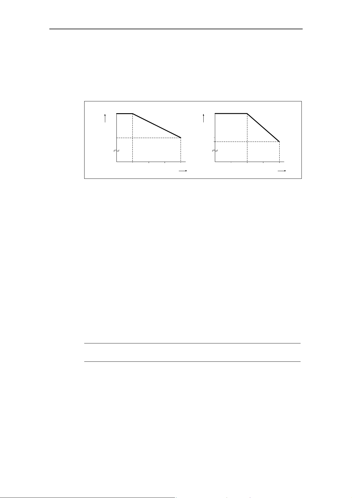
2.1 General
Installation after a Period of Storage
Following a prolonged period of storage, you must reform the capacitors in the
inverter. The requirements are listed below.
Voltage
[%]
100
75
50
0,5 1
2468
Storage period less than 1 year:
Storage period 1 to 2 years Prior to energizing, connect to
Storage period 2 to 3 years Prior to energizing, form
Storage period 3 and more years Prior to energizing, form
Fig. 2-1 Forming
2.2 Ambient operating conditions
Temperature
Permissible output current
100
[%]
75
No action necessary
voltage for one hour
according to the curve
according to the curve
Time t [h]
50
25
-10
0
20 301040
Operating temperature
50
60
[°C]
Fig. 2-2 Ambient operating temperature
MICROMASTER 420 Operating Instructions
6SE6400-5AA00-0BP0
23
2 Installation Issue 07/04
Humidity
Relative air humidity ≤ 95% Non-condensing
Altitude
If the inverter is to be installed at an altitude > 1000 m or > 2000 m above sea
level, derating will be required:
Permissible output current
100
%
80
01000
Installation altitude in m above sea level
Fig. 2-3 Installation altitude
Shock and Vibration
Do not drop the inverter or expose to sudden shock. Do not install the inverter in an
area where it is likely to be exposed to constant vibration.
Mechanical strength to DIN IEC 68-2-6
Deflection: 0.075 mm (10 ... 58 Hz)
Acceleration: 9.8 m/s
Electromagnetic Radiation
Do not install the inverter near sources of electromagnetic radiation.
Atmospheric Pollution
Do not install the inverter in an environment, which contains atmospheric pollutants
such as dust, corrosive gases, etc.
2000
3000 4000
2
(> 58 ... 500 Hz)
Permissible input voltage
100
%
80
77
01000
Installation altitude in m above sea level
2000
3000 4000
Water
Take care to site the inverter away from potential water hazards, e.g. do not install
the inverter beneath pipes that are subject to condensation. Avoid installing the
inverter where excessive humidity and condensation may occur.
Installation and cooling
MICROMASTER 420 Operating Instructions
24 6SE6400-5AA00-0BP0
CAUTION
The inverters MUST NOT be mounted horizontally.
The inverters can be mounted without any clearance at either side.
Allow 100 mm clearance above and below the inverter. Make sure that the cooling
vents in the inverter are positioned correctly to allow free movement of air.
Issue 07/04 2 Installation
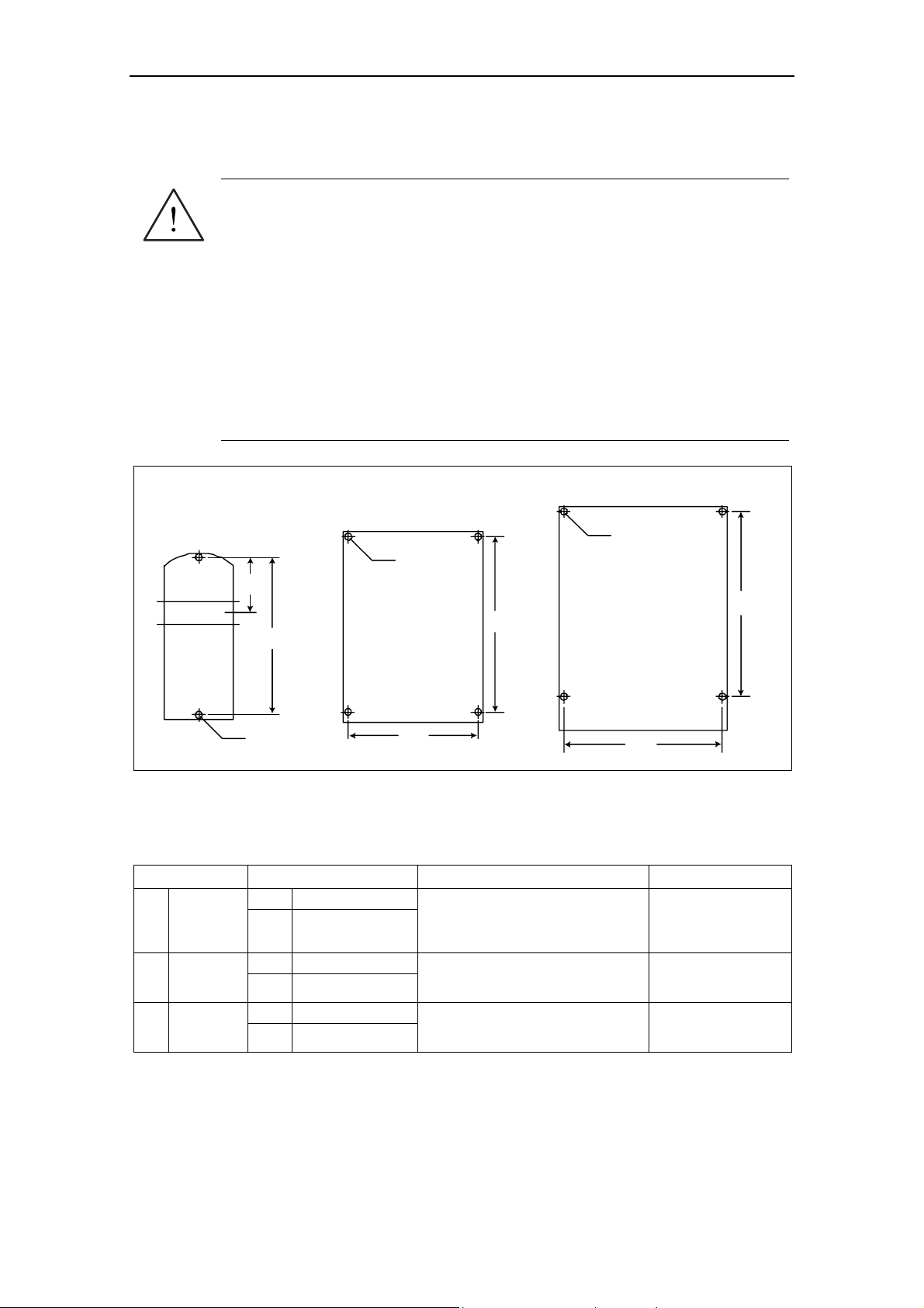
2.3 Mechanical installation
WARNING
♦ To ensure the safe operation of the equipment, it must be installed and
commissioned by qualified personnel in full compliance with the warnings laid
down in these operating instructions.
♦ Take particular note of the general and regional installation and safety
regulations regarding work on dangerous voltage installations (e.g. EN
50178), as well as the relevant regulations regarding the correct use of tools
and personal protective gear.
♦ The mains input, DC and motor terminals, can carry dangerous voltages even
if the inverter is inoperative; wait 5 minutes to allow the unit to discharge after
switching off before carrying out any installation work.
♦ The inverters can be mounted adjacent to each other. If they are mounted on
top of each other, however, a clearance of 100 mm has to be observed.
4
Frame Size A Frame Size B
Ø 4.8 mm
55 mm
2.2"
160 mm
6.30"
Ø 4.5 mm
0.17"
0.19"
138 mm
5.43"
174 mm
6.85"
Frame Size C
Ø 5.5 mm
0.22"
174 mm
6.85"
204 mm
8.03"
Fig. 2-4 Drill pattern for MICROMASTER 420
Table 2-1 Dimensions and Torques of MICROMASTER 420
Frame-Size Overall Dimensions Fixing Method Tightening Torque
2 x M4 Bolts
2 x M4 Nuts
2 x M4 Washers for mounting on
standard rail
4 x M4 Bolts
4 x M4 Nuts
4 x M4 Washers
4 x M5 Bolts
4 x M5 Nuts
4 x M5 Washers
2.5 Nm
with washers fitted
2.5 Nm
with washers fitted
2.5 Nm
with washers fitted
A
B
C
Width x
Height x
Depth
Width x
Height x
Depth
Width x
Height x
Depth
mm 73 x 173 x 149
inch 2.87 x 6.81 x 5.87
mm 149 x 202 x 172
inch 5.87 x 7.95 x 6.77
mm 185 x 245 x 195
inch 7.28 x 9.65 x 7.68
MICROMASTER 420 Operating Instructions
6SE6400-5AA00-0BP0
25
2 Installation Issue 07/04
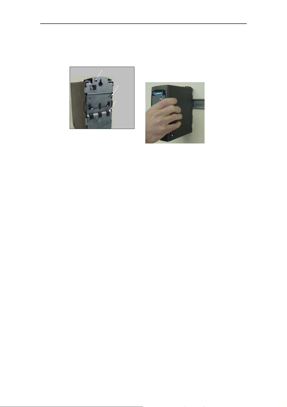
2.3.1 Mounting on standard rail, Frame Size A
Fitting the Inverter to a 35 mm standard rail (EN 50022)
Release Mechanism
Upper
rail latch
Lower
rail latch
Removing the Inverter from the rail
1. To disengaged the release mechanism of the inverter, insert a screwdriver into
the release mechanism.
2. Apply a downward pressure and the lower rail latch will disengage.
3. Pull the inverter from the rail.
1. Fit the inverter to the rail using the upper rail
latch.
2. Push the
inverter
against the
rail and the
lower rail
latch should
click into
place.
MICROMASTER 420 Operating Instructions
26 6SE6400-5AA00-0BP0

Issue 07/04 2 Installation
2.4 Electrical installation
WARNING
The inverter must always be grounded.
♦ To ensure the safe operation of the equipment, it must be installed and
commissioned by qualified personnel in full compliance with the warnings laid
down in these operating instructions.
♦ Take particular note of the general and regional installation and safety
regulations regarding work on dangerous voltage installations (e.g. EN
50178), as well as the relevant regulations regarding the correct use of tools
and personal protective gear.
♦ Never use high voltage insulation test equipment on cables connected to the
inverter.
♦ The mains input, DC and motor terminals, can carry dangerous voltages even
if the inverter is inoperative; wait 5 minutes to allow the unit to discharge
after switching off before carrying out any installation work.
CAUTION
The control, power supply and motor leads must be laid separately. Do not feed
them through the same cable conduit/trunking.
MICROMASTER 420 Operating Instructions
6SE6400-5AA00-0BP0
27

2 Installation Issue 07/04
2.4.1 General
WARNING
The inverter must always be grounded. If the inverter is not grounded correctly,
extremely dangerous conditions may arise within the inverter, which could prove
potentially fatal.
Operation with ungrounded (IT) supplies
It is not permissible to connect MICROMASTER 4 drive converters equipped with
integrated filter to non-grounded line supplies.
If connected to non-grounded line supplies, the 'Y' capacitor must be disabled in
the device. The procedure is described in Attachment B.2.
The MICROMASTER operates on non-grounded line supplies and remains
operational if an input or output phase is connected to ground. In this particular
case, an output reactor must be installed.
Operation with Residual Current Device
If an RCD (also referred to as ELCB or RCCB) is fitted, the MICROMASTER
inverters will operate without nuisance tripping, provided that:
A type B RCD is used.
The trip limit of the RCD is 300mA.
The neutral of the supply is grounded.
Only one inverter is supplied from each RCD.
The output cables are less than 50m (screened) or 100m (unscreened).
Operation with long cables
All inverters will operate at full specification with cable lengths up to 50 m screened
or 100 m unscreened.
When using output reactors as shown in Catalog DA 51.2, the following cable
lengths are possible for all of the types of construction/sizes:
Shielded: 200 m
Non-shielded: 300 m
MICROMASTER 420 Operating Instructions
28 6SE6400-5AA00-0BP0
Issue 07/04 2 Installation
2.4.2 Power and motor connections
WARNING
The inverter must always be grounded.
♦ Isolate the mains electrical supply before making or changing connections to
the unit.
♦ Ensure that the motor is configured for the correct supply voltage: single /
three-phase 230 V MICROMASTERS must not be connected to a 400 V
three-phase supply.
♦ When synchronous motors are connected or when coupling several motors in
parallel, the inverter must be operated with voltage/frequency control
characteristic (P1300 = 0, 2 or 3).
CAUTION
After connecting the power and motor cables to the proper terminals, make sure
that the covers have been replaced properly before supplying power to the unit!
NOTICE
♦ Ensure that the appropriate circuit-breakers/fuses with the specified current
rating are connected between the power supply and inverter (see chapter 5,
Tables starting on page 160).
♦ Use Class 1 60/75
o
C copper wire only (for UL compliance). For tightening
torque see Table 5-2, page 159.
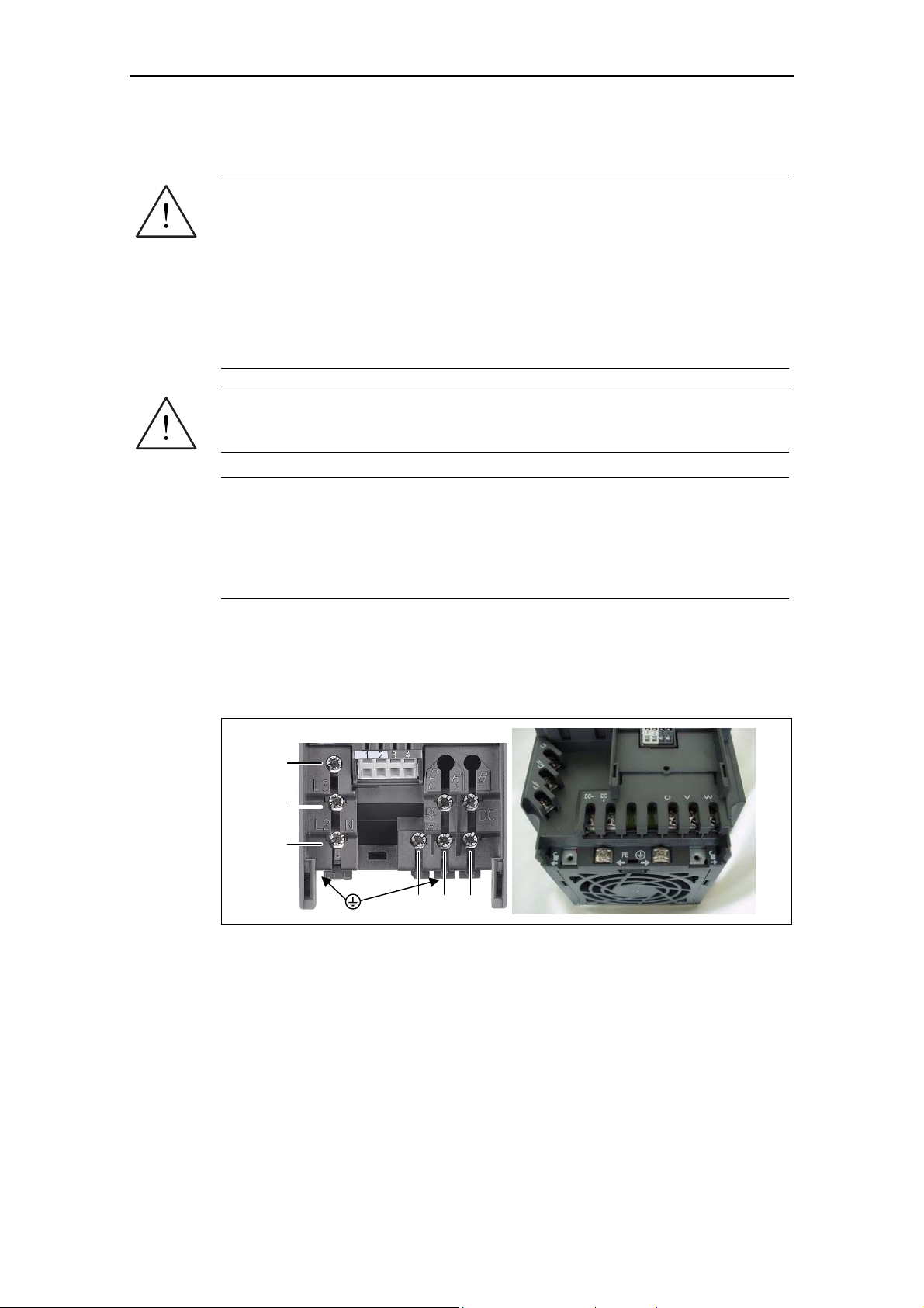
Access to the power and motor terminals
You can gain access to the mains and motor terminals by removing the covers
(see also Appendices A and B).
The mains and motor connections must be made as shown in Fig. 2-6.
L3
L2/N
L1/L
UVW
Fig. 2-5 MICROMASTER 420 connection terminals
MICROMASTER 420 Operating Instructions
6SE6400-5AA00-0BP0
29
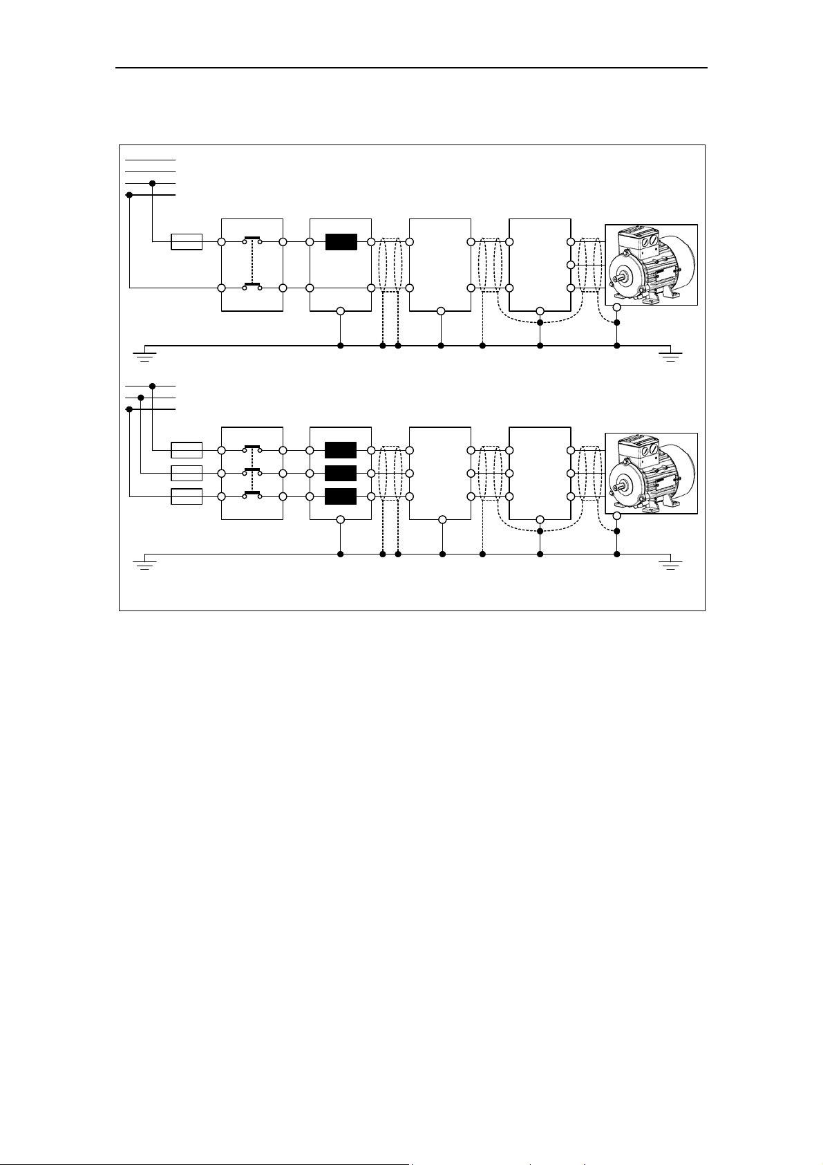
2 Installation Issue 07/04
L3
L2
L1
N
Fuse
L3
L2
L1
Fuse
Contactor
Contactor
Single Phase
Optional
line choke
PE
Three Phase
Optional
line choke
PE
Optional
Filter
PE
Optional
Filter
PE
MICROMASTER
L/L1
U
V
N/L2
W
PE
MICROMASTER
L3
U
L2
V
L1
W
PE
1)
1)
Motor
Motor
1) with and without filter
Fig. 2-6 Motor and Power Connections
MICROMASTER 420 Operating Instructions
30 6SE6400-5AA00-0BP0
Loading...