


KVM 3-1621
Table of contents
 Loading...
control
3
User Guide
KVM series3-1621
Keyboard/Video/Mouse Switch English
USA Notification
Warning: Changes or modifications to this unit not expressly approved by the party
responsible for compliance could void the user’s authority to operate the equipment.
Note: This equipment has been tested and found to comply with the limits for a Class
A digital device, pursuant to Part 15 of the FCC Rules. These limits are designed
to provide reasonable protection against harmful interference when the equipment
is operated in a commercial environment. This equipment generates, uses and can
radiate radio frequency energy and, if not installed and used in accordance with
the instruction manual, may cause harmful interference to radio communications.
Operation of this equipment is a residential area is likely to cause harmful
interference, in which case the user will be required to correct the interference at his/
her own expense.
Canadian Notification
This Class A digital apparatus complies with Canadian ICES-003.
Cet appareil numérique de la classe A est conforme à la norme NMB-003 du
Canada.
Japanese Notification
Korean Notification
Safety and EMC Approvals and Markings
UL, FCC, cUL, ICES-003, CE, GS, VCCI, MIC, C-Tick, GOST
Safety certifications and EMC certifications for this product are obtained under one
or more of the following designations: CMN (Certification Model Number), MPN
(Manufacturer’s Part Number) or Sales Level Model designation. The designation
that is referenced in the EMC and/or safety reports and certificates are printed on the
label applied to this product.

KVM s3-1621 and s3-1641
User Guide
Edition July 2007

Comments... Suggestions... Corrections
The User Documentation Department would like to know your opinion of this manual.
Your feedback helps us optimize our documentation to suit your individual needs. Fax
forms for sending us your comments are included in the back of the manual. There you
will also find the addresses of the relevant User Documentation Department.
Certified documentation
according to DIN EN ISO 9001:2000
To ensure a consi stently high qual ity stand ard and us er-friendli ness, thi s documenta tion
was created to meet the regulations of a quality management system which complies
with the requirements of the standard DIN EN ISO 9001:2000.
Copyright and Trademarks
Copyright © 2006 Fujitsu Siemens computers GmbH.
All rights reserved.
Delivery subject to availability; right of technical modifications reserved.
All hardware and software names used are trademarks of their respective
manufacturers.
This manual is printed on
paper treated with
chlorine-free bleach.

Contents
590-591-609B
Contents
1 Product overview ....................................................................................1
1.1 Glossary....................................................................................................1
1.2 Notational Conventions.............................................................................1
1.3 Features and benefits................................................................................2
1.3.1 KVM-IA Intelligent Adapters......................................................................3
1.3.2 Virtual Media .............................................................................................4
1.3.3 OSCAR graphical user interface ...............................................................4
1.3.3.1 Security .....................................................................................................4
1.3.3.2 Operation modes.......................................................................................4
1.3.4 Video.........................................................................................................4
1.3.5 Flash upgradability....................................................................................5
1.3.6 Accessing the appliances through a network connection..........................5
1.3.7 Accessing target devices...........................................................................5
1.3.8 On-board web interface.............................................................................5
2 Installation ...............................................................................................7
2.1 Installation overview..................................................................................7
2.1.1 Installing a KVM s3-1621 or KVM s3-1641 appliance...............................7
2.1.2 Setting up the network...............................................................................8
2.2 Required items.............. ..... .................................. ...... ..... ..........................9
2.3 Safety precautions.....................................................................................9
2.3.1 General......................................................................................................9
2.4 Rack mounting a KVM appliance............................................................10
2.4.1 General guidelines..................................................................................10
2.4.2 Installing a KVM appliance in the rack mounting space..........................11
2.5 Connecting the KVM applianc e hardwa re................................... ............12
2.5.1 Connecting a KVM-IA to each target device............................................12
2.5.2 Connecting local peripheral devices........................................................12
2.6 Verifying Ethernet connections................................................................13
2.7 Configuring the KVM s3 Client...............................................................13
2.8 Adjusting mouse settings ........................................................................13
2.9 Attaching earlier app liance models to a KVM s3-1621 or s3-1641 appli ance
13
2.9.1 Attaching an incompatible switch model..................................................14
2.10 Setting up the KVM s3-1621 and
KVM s3-1641 appliances15
3 Basic operations .......................................... ...... ...................................17
3.1 Controlling the switching system from the analog port............................17
3.2 Starting the OSCAR interface .................................................................17

Contents
590-591-609B
3.3 Setting a screen delay.............................................................................19
3.4 Connecting a user to a target device..................................... ..................19
3.5 Selecting the previously selected target device.......................................19
3.6 Disconnecting the user from a target device...........................................19
3.7 Using the OSCAR interface.....................................................................20
3.8 Connecting local virtual media.................................................................21
3.9 Configuring the appliances and the OSCAR interface............................22
3.9.1 Assigning target device names ...............................................................23
3.9.2 Assigning appliance and device types ....................................................25
3.9.2.1 Accessing the Devices window...............................................................25
3.9.2.2 Assigning a switch type...........................................................................26
3.9.3 Changing the display behavior................................................................26
3.9.3.1 Selecting the order of the target devices.................................................27
3.9.3.2 Select, complete the following steps.......................................................27
3.9.3.3 Setting up a screen delay........................................................................27
3.9.4 Selecting the display language................................................................28
3.9.5 Controlling the status flag........................................................................28
3.9.6 Setting the keyboard country code..........................................................30
3.9.7 Setting KVM s3-1621 and KVM s3-1641 appliancesecurity...................31
3.9.7.1 Enabling the screen saver.......................................................................31
3.9.7.2 Disabling the screen saver......................................................................31
3.9.7.3 Setting or change a password.................................................................31
3.9.7.4 Recovering a password...........................................................................32
3.9.7.5 Disabling password protection.................................................................32
3.10 Setting the preemption warning...............................................................32
3.11 Managing target device tasks using the OSCAR interface......................33
3.11.1 Accessing the Commands window..........................................................34
3.11.2 Displaying version information.................................................................34
3.11.3 Upgrading the firmware...........................................................................35
3.11.4 Viewing the display configuration............................................................36
3.11.5 Viewing and disconnecting user connections..........................................36
3.11.5.1 Viewing current user connections............................................................36
3.11.5.2 Disconnecting a user...............................................................................37
3.11.6 Resetting the keyboard and mouse values............................................38
3.12 Scanning the switching system...............................................................39
3.12.1 Adding target devices to the scan list......................................................39
3.12.2 Removing a target device from the scan list............................................40
3.12.3 Starting the scan mode...........................................................................40
3.12.4 Canceling scan mode..............................................................................41
3.13 Running switching syst em dia gno st ic tes ts.............................................41

Contents
590-591-609B
4 Computer terminal operations.............................................................43
4.1 The Console menu..................................................................................43
4.1.1 Configuring network settings...................................................................43
4.1.2 Configuring network speed settings........................................................44
4.1.3 Other Console Main menu options..........................................................45
4.1.3.1 Security Configuration.............................................................................45
4.1.3.2 Firmware Management............................................................................45
4.1.3.3 Enable Debug Messages ........................................................................45
4.1.3.4 Restore Factory Defaults.........................................................................45
4.1.3.5 Reset the KVM s3-1621 or KVM s3-1641 appliance...............................45
4.1.3.6 Exit ..........................................................................................................45
5.1 Flash upgrades........................................................................................47
5.1.1 Upgrading the firmware using the KVM s3 Client....................................47
5.1.2 Upgrading the firmware using the Console menu...................................47
5.1.3 Repairing damaged firmware ..................................................................48
5.2 Virtual media ...........................................................................................48
5.2.1 Virtual media and USB 2.0 constraints....................................................48
5.2.2 Booting a computer using virtual memory...............................................49
5.2.2.1 Determining if your computer can be booted from virtual media.............49
5.2.2.2 Virtual media restrictions.........................................................................50
5.3 UTP cabling........................ ...... ...... ..... ...... ....................................... .......50
5.3.1 UTP copper cabling......................................................... ........................50
5.3.2 Wiring standards .....................................................................................51
5.3.3 Cabling installation, maintenance, and safety tips...................................51
5.4 Technical specifications ..........................................................................52
5.5 Technical Support ...................................................................................54
5.5.1 Before you call.........................................................................................54

Contents
590-591-609B

1
590-591-609B
1 Product Overview
The KVM s3-1621and the KVM s3-1641 appliances integrate digital and analog
keyboard, video, and mouse (KVM) switching technology with advanced cable
management, access for two or four simultaneous users, and a user interface. The
appliances have USB and PS/2
®
ports on the rear panel that support all major target
device platforms.
1.1 Glossary
The following terms are used throughout this document:
• ACI Port - ACI stands for “analog console interface ”. Th is is a po rt on some Fujitsu
Siemens KVM switches that acts as an integrated KVM-IA adapter for tiering
purposes.
• ARI Port - ARI stands for “analog rack interface”. The ARI Port is used to connect
computers and KVM switches to KVM series2 and series3 KVM switches via a
KVM-IA adapter.
• KVM s3-1621 and KVM s3-1641 appliances - equipment that provides KVM-over-
IP connectivity to attached target devices. The term appliance is used in this
manual to refer to a KVM switch managed by the KVM s3 Client.
• KVM-IA - (Keyboard/Video/Mo use-Interfa ce Adapter) - adapte r that, wh en attache d
to the appliance and a target device, provides additional functionality, such as
virtual media sessions
• switching system - a set of appliances and attached target devices and KVM-IAs
• target device - equipment such as a server or router that is attached to
an appliance by a KVM-IA
• local user - person with access to the keyboard, monitor, and mouse directly
connected to the appliance. This user has full acc es s to all t arg et dev ice s.
• remote user - an account in the local appliance user database or on a centralized
Active Directory server. This account is used to provide management access to an
appliance and its attached devices.
• virtual media - a USB media device that can be attached to the KVM s3-1621 and
KVM s3-1641 applian ces and made av ailable to any tar get devic e that is co nnected
to a KVM s3-1621 or KVM s3-1641 appliance
1.2 Notational Conventions
The following notational conventions are used in this manual:
Bold This indicates emphasis in the text.
Key This indicates keys or key combinations in continuous text.
Italics This indicates commands, file names, menu names, and
inputs in continuous text.
This indicates additional information and tips.
Product Overview
2
590-591-609B
1.3 Features and benefits
The KVM s3-1621 and KVM s3-164 1 appliances are rack-moun table KVM switc hes that
are configurable for analo g (loc al ) or digit al (rem ote ) con nec tiv ity . Vide o res olu tio ns are
supported up to 1280 x 1024 for remote users.
The KVM s3-1621 appliance includes two digital port sets for KVM-over-IP access, 1
analog port set for KVM access, 16 analog rack interface (ARI) ports for connecting
KVM-IAs and target devices, and virtual media capability for one local user and up to
two remote users.
The KVM s3-1641 appliance includes four digital ports for KVM-over-IP access, 1
analog port set for KVM access, 16 ARI ports for connecting KVM-IAs and target
devices, and virtual media capability for one local user and up to four remote users.
Both appliances can be used with the KVM s3 Client application to view and control
these appliances as well as the legacy KVM series2 (KVM2-1611) appliance and
attached target devices. For more information about the KVM s3 Client, refer to the
Managing KVM Appliances User Guide.
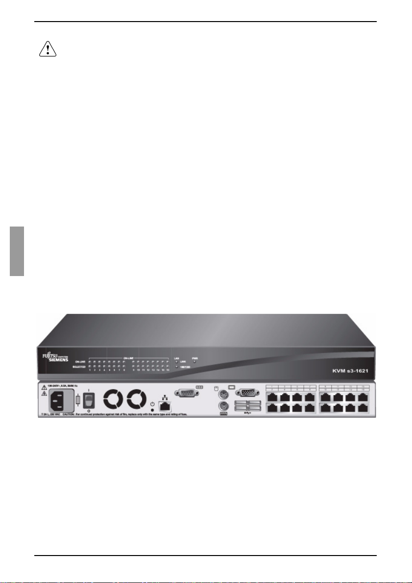
Figure 1: KVM s3-1621 appliance
This indicates information, which if not heeded, may
jeopardize your health, the functioning of your system, or
the security of your data.
This indicates a step that you have to perform.
- and • These characters symbolize itemized lists.
Bold monospace font This indicates user inputs in examples.
Titl
e
KVM-IA Intelligent Adapters
3
590-591-609B
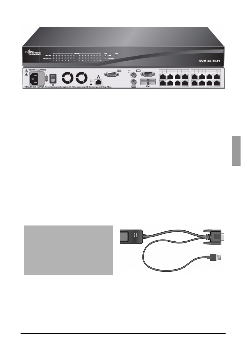
Figure 2: KVM s3-1641 appliance
The KVM s3-1621 and KVM s3-1641 appliances have user peripheral ports for PS/2
®
and USB keyboards and mice. Additionally, virtual media, such as generic removable
media and CD drives, can be connected to any one of four USB ports.
The KVM s3-1621 and KVM s3-1641 appliances work over standard LAN connections.
Users can access target devices across a 1000BASE-T LAN port that is used to
establish an Ethern et connection, or direct ly through a local port. The IP-based KVM s 3-
1621 and KVM s3-1641 appliances give you target device control from anywhere in
the world.
1.3.1 KVM-IA Intelligent Adapters
You can use the following KVM-IAs with the KVM s3-1621 and KVM s3-1641
appliances:
• KVM S2-Adapter PS/2-VGA - PS/2 and VGA connectors
• KVM s2-Adapter SUN-VGA - PS/2 and VGA connectors
• KVM s3-Adapter USB2-VGA - USB2 and VGA connectors, required for virtual
media connections
• KVM s2-Adapter 1.1 USB-VGA - USB and VGA connectors
Figure 3: Examples of KV M-IAs
These intelligent KVM-IAs with Cat 5 design dramatically reduce cable clutter while
providing optim al digita l displa y resolu tion and video se ttings. Th e built-i n memory of the
KVM-IA simplifies configuration by assigning and retaining unique target device
identification codes for each attached target device. This integrated intelligence
enhances security and prevents unauthorized access to a target device through cable
PS/2 and VGA connectors KVM s3-Adapter USB2-VGA

Product Overview
4
590-591-609B
manipulation. Th e KVM-IA is pow ered d irectly f rom the ta rget de vice an d prov ides Keep
Alive functionality when the KVM s3-1621 or KVM s3-1641 appliance is not turned on.
The KVM-IAs enable direct KVM connectivity to target devices that are attached to the
KVM s3-1621 or KVM s3-1641 appliance. Each KVM s3-1621 and KVM s3-1641
appliance has 16 ARI ports for connecting KVM-IAs.
The KVM-IAs that work with the appliances support target devices with PS/2 and USB
ports as well as SUN 8-pin ports for keyboard and mouse. When using the OSCAR
interface in conjunction with KVM-IAs, you can easily switch between platforms.
1.3.2 Virtual Media
The KVM s3-1621 and KVM s3-16 41 appliances support virtual med ia w he n co nn ect ed
to a KVM-IA. You can use virtual media support to connect USB media devices to a
KVM s3-1621 or KVM s3-1641 appliance and make those devices available to any
connected appliances.
Use virtual media to move data between a target device and USB media devices that
are connected to the KVM s3-1621 and KVM s3-1641 appliances. You can install,
upgrade, or recover the operating system; update the BIOS code; or start the target
device from a USB drive through the virtual media capabilities of the KVM s3-1621 and
KVM s3-1641 appliances.
Virtual media can be connected directly to the KVM s3-1621 and KVM s3-1641
appliances using one of four USB ports on these appliances. In addition, virtual media
can be connected to any remote workstation that is running the KVM s3 Client and is
connected to the appliance using an Ethernet connection. To open a virtual media
session with a target device, the target device must first be connected to the appliance
using a KVM s3-Adapter USB2-VGA cable. For more information about the on-board
web interface, refer to the Virtual Media Guide.
1.3.3 OSCAR graphical user interface
The KVM s3-1621 and KVM s3-1641 appliances use the OSCAR
®
for Fujitsu-Siemens
Computers graphica l user interf ace, which h as menus to c onfigure the switchi ng syste m
and to select computers. You can list target devices by unique name, EID (Electronic
ID), or port number.
1.3.3.1 Security
Use the OSCAR interface to protect the switching system with a screen saver
password. After a user-defined time, the screen saver mode engages and access is
prohibited until the correct password is entered to reactivate the switching system.
1.3.3.2 Operation modes
The OSCAR user in terfa ce pro vi des v ario us operation modes for s yst em administration
of the KVM s3-1621 and KVM s3-1641 appliances. Use these modes (Scan, Switch,
and Share) to manage the switching activities. See Chapter 3, “Basic operations”,
beginning on page 17 for more information.
1.3.4 Video
The KVM s3-1621 and KVM s3-1641 appliances provide optimal resolution for analog
VGA, SVGA, and XGA video. You can achieve resolutions of up to 1280 x 1024

Flash upgradability
5
590-591-609B
depending upon th e length of cable that is sepa rating t he KVM s3-1 621 or KVM s3-1641
appliance and target devices.
1.3.5 Flash upgradability
Upgrade the KVM s3-1621 and KVM s3-1641 appliances at any time through the
network port to ensure the KVM s3-1621 or KVM s3-1641 appliance is always running
the most current available version. See Appendix 5.1 on page 47 for detailed
information.
1.3.6 Accessing the appliances through a
network connection
Users access the KVM s3-1621 and KVM s3-1641 appliances and all attached target
devices through the Ethernet from a client computer. A c lient computer can be
anywhere a va lid network connection exists.
1.3.7 Accessing target devices
When you access the KVM s3 Client, a listing of all target devices you have permission
to view and manage opens. When you select a target device from the list, the video of
the selected target device opens in a Video Viewer window.
1.3.8 On-board web interface
The on-board web interface provides similar management functions as the KVM s3
Client, but does not require a software server or any installation. The on-board web
interface is launched directly fro m the applianc e, and any s ervers connec ted to the KVM
s3-1621 and KVM s3-1641 appliances are automatically detected. You can use the on-
board web interface to configure KVM s3-1621 and KVM s3-1641 appliances from a
web browser. Launch the Viewer fro m the on-b oard web inte rface to es tabli sh KVM and
virtual media sessions to target devices. For more information about the on-board web
interface, refer to the M an agi ng KVM Appl ian ce s User Gu ide.
Product Overview
6
590-591-609B
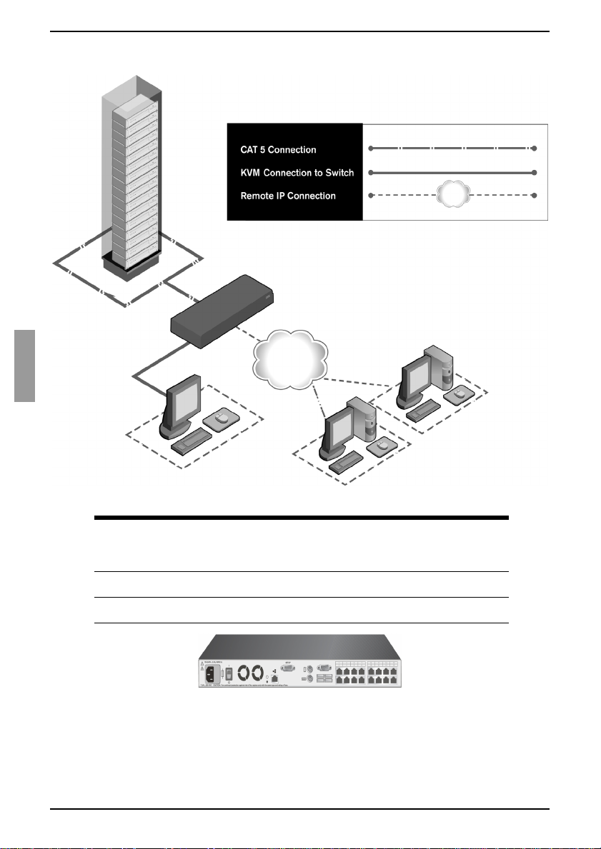
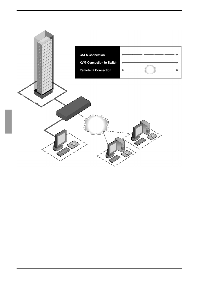
Figure 4 illustrates a typical KVM s3-1621 or KVM s3-1641 appliance configuration.
Figure 4: Example KVM s3-1621 or KVM s3-1641 appliance configuration
Figure 5: KVM s3-1621 and KVM s3-1641 appliance model comparison
Digital user
Analog user
KVM s3-1621 or KVM s3-1641
Ethernet
Digital user
Rack of
target servers
appliance
KVM appliance
models
Number of
ARI ports
Digital
paths
Analog
user
Local virtual
media
sessions
Remote
virtual media
sessions
s3-1621 16 2 1 1 2
s3-1641 16 4 1 1 4

7
590-591-609B
2Installation
The KVM s3-1621 and KVM s3-1641 appliances require connectivity to a computer
running the KVM s3 Client. Use the KVM s3 Client to view and control target devices
(one at a time) attached to a KVM s3-1621 or KVM s3-1641 appliance. The analog port
does not require the KVM s3 Client for operation. The analog port uses OSCAR for the
Fujitsu Siemens graphical user interface. For more information, see Chapter 3, “Basic
operations”, beginning on page 17, or the KVM s3 Client User Guide.
The KVM s3-1621 and KVM s3-1641 appliances transmit KVM information between
operators and target devices attached to another appliance over a network using either
an Ethernet or local connec tion.
The KVM s3-1621 and KVM s3-1641 appliances use TCP/IP for communication over
Ethernet. Although 10BASE-T Ethernet can be used, using a dedicated, switched
100BASE-T network or a 1000BASE-T network will improve performance.
2.1 Installation overview
2.1.1 Installing a KVM s3-1621 or KVM s3-1 641 appliance
Unpack the KVM s 3-1621 o r KVM s3-1641 applian ce and ve rify that al l compo nents
are present and in good condition. See section 2.2 Required items on page 9 for
additional information.
Make all hardware connections between the power source, the KVM s3-1621 or
KVM s3-1641 appliance, target devices, KVM-IAs, and Ethernet. See section 2.3
Safety precautions on page 9 for more information.
Turn on the power and verify that all connections are working. See section 2.6
Verifying Ethernet connections on page 13 for instructions.
To configure the KVM s3-1621 or KVM s3-1641 appliance, complete one of the
following steps:
• Use the console menu interface to configure the KVM s3-1621 or
KVM s3-1641 appliance. See Chapter 4, “Computer terminal operations”,
beginning on page 43 for instructions.
-or-
• Use the KVM s3 Client to configure the KVM s3-1621 or KVM s3-1641
appliance. See the KVM s3 Client User Guide for detailed instructions.
Make the needed mouse setting adjustments. See section 2.8 Adjusting mouse
settings on page 13 for instructions.
Installation
8
590-591-609B
Figure 6 illustrates one possible configuration for the KVM s3-1621 or KVM s3-1641
appliance.
Figure 6: Example KVM s3-1621 or KVM s3-1641 appliance configuration
2.1.2 Setting up the network
The KVM s3-1621 and KVM s3-1641 appliances and KVM-IAs use IP addresses to
uniquely identify the appliances and the target devices. These appliances support both
Dynamic Host configuration Protocol (DHCP) and static IP addressing. To avoid
confusion, have IP addresses that are reserved for each appliance and remain static
while the applia nce s are co nn ect ed to the network. For addi tio nal i nfo rma t ion o n s ett ing
up the KVM s3-1621 and KVM s3-1641 appliances using the KVM s3 Client, and for
information on h ow the KVM s3-1621 and KVM s 3-1641 appli ances use TCP/IP, s ee the
KVM s3 Client Installation and User’s Guide.
Digital user
Analog user
KVM s3-1621 or KVM s3-1641
Ethernet
Digital user
Rack of
target servers
appliance

Required items
9
590-591-609B
2.2 Required items
Before you install a KVM s3-1621 or KVM s3-1641 appliance, make sure that you have
all the required items. The following items come with the KVM s3-1621 and
KVM s3-1641 appliances:
• Power cord (US)
• One serial cable
• Rack-mounting brackets
• KVM s3 Client, Firmware, and Documentation CD
• Quick Installation Guide
In addition to the ite ms that com e with the KVM s 3-1621 or KVM s3-1641 a ppliance, yo u
must provide one KVM-IA (virtual media, KVM, or USB) and one Cat 5 patch cable for
each attached target device or KVM s3-1621 and KVM s3-1641 appliances. A Phillips
and a hex screwdriver is also needed for rack-mounting the KVM s3-1621 and
KVM s3-1641 appliances.
2.3 Safety precautions
Observe the following guidelines to safely operate the equipment.
2.3.1 General
• Observe and follow service markings.
• Do not service any KVM s3-162 1 or KVM s3-1641 appli ance excep t as explain ed in
the KVM s3-1621 and KVM s3-1641 appliance documentation.
• The KVM s3-1621 and KVM s3-1641 appliances contain no serviceable
components. Do not attempt to open the KVM s3-1621 and KVM s3-1641
appliances as doing so may void customer warranty.
• Opening or removing covers t hat are marked with the triangular symbol with a
lightning bolt might expose you to electrical shock. Components inside these
compartments must be serviced only by a trained service technician.
• If any of the following conditions occur, disconnect the KVM s3-1621 or KVM s3-
1641 appliance from th e ele ctri ca l out let an d rep lac e the p art or co ntact the trained
service provider:
• The power c able, extension cable, or connector is damaged.
• An object has fallen into the product.
• The KVM s3-1621 or KVM s3-1641 appliance has been exposed to water.
• The KVM s3-1621 or KVM s3-1641 appliance has been dropped or damaged.
• The KVM s3-1621 or KVM s3-1641 appli anc e doe s not operate properly when
you follow the operating instructions.
• Keep the KVM s3-1621 a nd KVM s3-1 641 applianc es away from ra diators and heat
sources. Also, do not block cooling vents.
• Do not spill food or liquids on the KVM s3-1621 or KVM s3-1641 appliance
components, and never operate the KVM s3-1621 and KVM s3 -164 1 ap pli anc es in
a wet environment. If the KVM s3-1621 or KVM s3-1641 appliance gets wet, see

Installation
10
590-591-609B
the applicable section in the troubleshooting guide or contact the trained service
provider.
• Use the KVM s3-1621 an d KVM s3 -1641 a pplia nces only with ap proved equipm ent.
• Operate the KVM s3-1621 or KVM s3-16 41 appliance onl y from the type of ex ternal
power source that is indicated on the elec trical ratings label. If you are not sure of
the type of power source that is required, consult the service provider or local power
company.
• Be sure that the monitor and attached devices are electrically rated to operate with
the power that is available in the current location.
• Use only power cables that are provided with the KVM s3-1621 and KVM s3-1641
appliances.
• To help prevent electric shock, connect the KVM s3-1621 or KVM s3-1641
appliance and peripheral power cables into properly grounded electrical outlets.
These cables are equipped with three-prong connectors to help ensure proper
grounding. Do not use adapter connectors or remove the grounding prong from a
cable.
• Observe extension cable and power strip ratings. Make sure that the total ampere
rating of all products that are connected to the power strip does not exceed 80
percent of the ampere ratings limit for the power strip.
• To help protect the KVM s3-1621 and KVM s3-1641 appliances from sudden,
transient increase s a nd de cre as es in el ec tric al p ow er, use a su rge s upp res so r, line
conditioner, or uninterruptible power supply.
• Carefully position KVM s3-1621 and KVM s3-1641 appliance cables and power
cables. Route cables so that they cannot be stepped on or tripped over. Be sure
that nothing rests on any cables.
• Do not modify power cables or connectors. consult a licensed electrician or the
power company for site modifications. Always follow the local and national wiring
rules.
2.4 Rack mounting a KVM appliance
Before installing the KVM s3-1621 or KVM s3-16 41 applianc e and o ther components in
the rack (if not already installed), stabilize the rack in a permanent location. Install the
equipment start ing a t the bottom of the rack, then work to the top. Avoid uneven loading
or overloading of racks.
2.4.1 General guidelines
• Refer to the rack installation documentation that accompanied t he rack for
specific caution statements and procedures.
• Elevated ambient temperature: In a closed rack assembly, the operation
temperature of the rack environment can be greater than room ambient. Use care
not to exceed the rated maximum ambient temperature of the unit.
• Reduced air flow: Carefully install the equipment in a rack so that an adequate
amount of airflow is maintained for safe operation of the equipment.
Installing a KVM appliance in the rack mounting space
11
590-591-609B
• Mechanical loading: Avoid a potentially hazardous condition caused by uneven
mechanical loading by carefully mounting the equipment in the rack.
• Circuit overloading: Consider the connection of the equipment to the supply
circuit and the effect that overloading of circuits might have on overcurrent
protection and supply wiring. Observe equipment nameplate ratings for
maximum current.
• Reliable earthing: Maintain reliable earthing of rack-mounted equipment. Pay
particular attention to supply connections other than direct connections to the
branch circuit (for example, use of power strips).
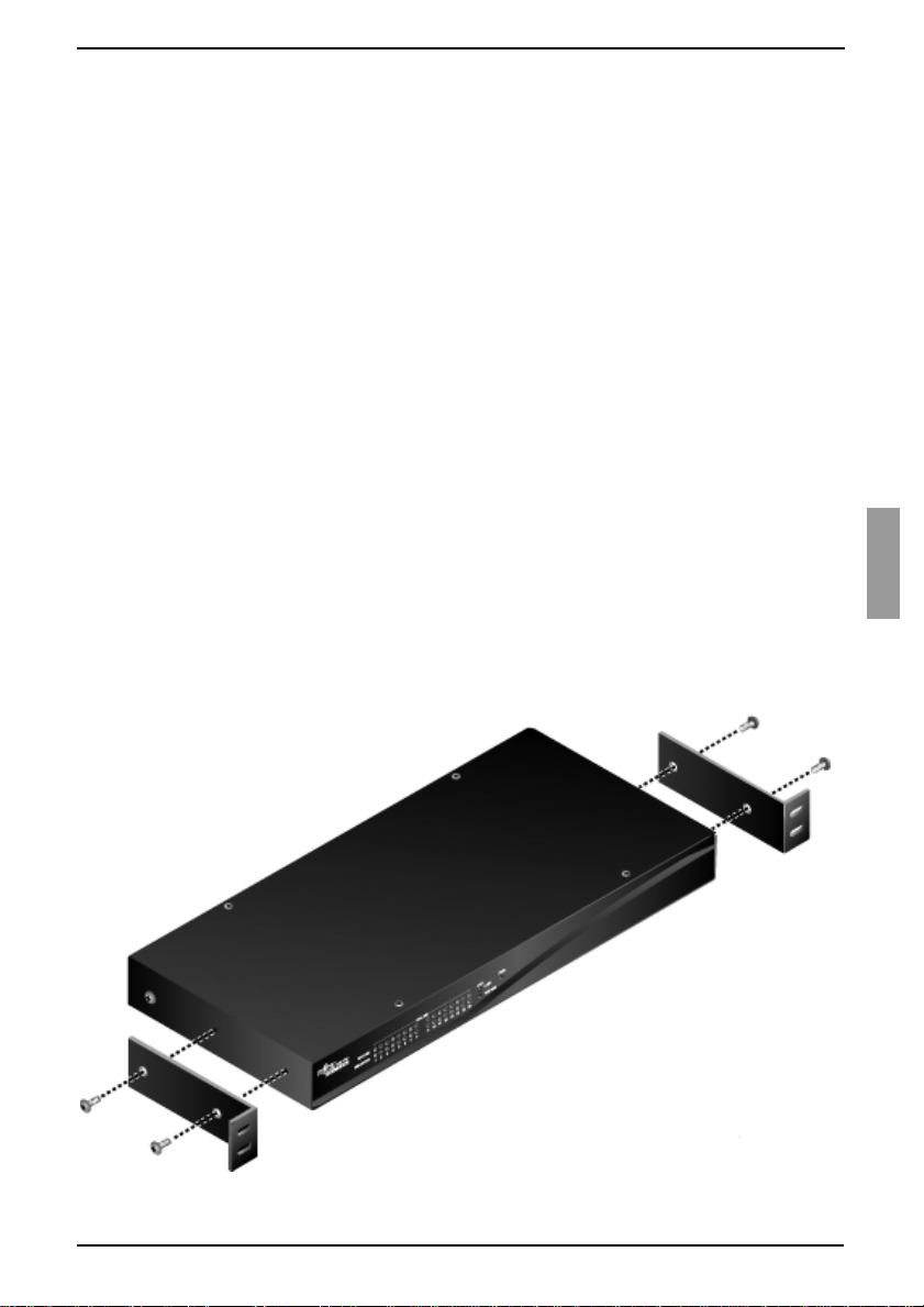
2.4.2 Installing a KVM appliance in the rack
mounting space
Remove the screws on each side of the KVM s3-1621 or KVM s3-1641 appliance.
Line up the holes in the long side of each mounting bracket.
With a Phillips screwdriver, fasten the mounting brackets to the KVM s3-1621 or
KVM s3-1641 appliance, using two 8/32-inch x 1/2-inch pan-head screws on
each side.
Attach four cage nut s or clip nuts to the rack mounting fl ange of the rack so tha t the
nut is positioned on the inside of the rack.
Mount the KVM s3-1621 or KVM s3-1641 appliance assembly to the rack by
matching the holes in the short side of each mounting bracket to a set of matching
holes on the rack. Insert the combination Phillips screws through the slots in the
mounting bracket and the holes in the mounting rail, then into the cage nuts or
clip nuts.
Figure 7: KVM s3-1621 and KVM s3-1641 appliance horizontal installation

Installation
12
590-591-609B
2.5 Conn ecting the KVM appliance hardware
Turn of f the t arget devices that are p art of the swi tching sys tem. Conn ect one end of
the power cord to the rear o f the KVM s3-162 1 or KVM s 3-1641 applianc e, and con-
nect the ot her end to an ac power source.
Connect a VGA monitor and either PS/2 or USB keyboard and mouse cables into
the labeled KVM s3-1621 or KVM s3-1641 appliance ports. You must install both a
keyboard and mouse on the local ports or the keyboard will not initialize correctly.
You cannot connect a DVI or EGA monitor to the KVM s3-1621 and KVM s3-1641
appliances.
Connect one end of a Cat 5 p atc h ca bl e (4-p a ir, up to 10 meters) into any ARI port,
and connect the other end into the RJ-45 connector of a KVM-IA.
Connect the KVM-IA into the correct ports on the rear of the target device. Repeat
this procedure f or all t ar get de vice s t hat are to be conn ected to th e KVM s3-1 621 o r
KVM s3-1641 appliance.
Connect a Cat 5 patch cable from the Ethernet network into the LAN port on the
rear panel of the KVM s3-1621 or KVM s3-1641 appliance. Network users will
access the appliance through this port.
If you are configuring the KVM s3-1621 and KVM s3-1641 appliances using the
console menu int erface, c onnect a compute r running terminal emulati on sof tware to
the IOIOI port on the rear panel of the appliance, using the supplied straight serial
cable. The terminal should b e set to 9 600 bit s per se cond (bp s), 8 bit s, 1 s top bit, n o
parity, and no flow control. Otherwise, proceed to the next step.
Turn on each target flag and then turn on the KVM s3-1621 or KVM s3-1641
appliance. After approximately one minute, the appliance completes initialization
and opens the OSCAR graphical user interface Free tag on the local port monitor.
Use the KVM s3 Client to configure your KVM s3-1621 or KVM s3-1641 appliance.
See the KVM s3 Client Installation and User’s Guide for detailed instructions.
2.5.1 Connecting a KVM-IA to each target device
Attach the color-coded connectors of the KVM-IA to the keyboard, monitor, and
mouse ports on the fi rst targe t devic e that yo u conn ect to the KVM s3-16 21 o r KVM
s3-1641 appliance.
Attach one end of the Cat 5 cable to the RJ-45 connector on the KVM-IA.
Connect the other end of t he Ca t 5 ca bl e to an y ARI port on the rear of the KVM s 3-
1621 or KVM s3-1641 appliance.
Repeat steps 1 to 3 for all target devices that you are attaching.
2.5.2 Connecting local peripheral devices
Connect a keyboard, monitor, and mouse to each set of color-coded ports on the
rear of the KVM s3-1621 or KVM s3-1641 appliance.
Bundle and label the cables for easy identification.
Verifying Ethernet connections
13
590-591-609B
2.6 Verifying Ethernet connections
The Ethernet conne ction has two LEDs. Th e gree n LED on the right is the Link indicato r.
It is lit when a valid c onnection to the network is estab lished, and it flashes w hen there i s
activity on the port. The amber/green LED on the left indicates that you are
communicating at 100 Mbps (amber) or 1000 Mbps (green) when using the Ethernet
connection.
2.7 Configuring the KVM s3 Client
See the KVM s3 Client Us er Guide included on the CD with the software.
2.8 Adjusting mouse settings
Before a computer connected to the KVM s3-1621 or KVM s3-1641 appliance can
be used for remote user control, you must set the target mouse speed and turn off
acceleration.
If you are experiencing slow mouse response during a remote video session,
deactivate mouse acceleration in the operating system of the target device and set
the mouse speed at 50%.
2.9 Attaching earlier appliance models to a
KVM s3-1621 or s3-1641 appliance
You can add earlier appliance models for integ r ati on i nto the ex ist ing configuration. In a
tiered system, each ARI port will accommodate one target device. When earlier
appliance models are tiered under the KVM s3-1621 or KVM s3-1641 appliance, the
KVM s3-1621 or KVM s3-1641 appliance must be at the top level of the tier. See the
following list for earlier appliance models that are compatible with the KVM s3-1621 or
KVM s3-1641 appliance configuration:
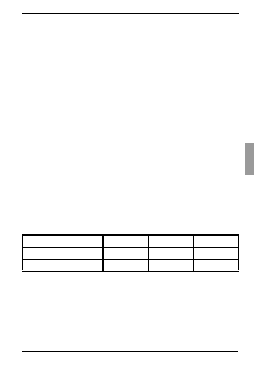
Table 1 lists earlier KVM appliance models.
Mount the earlier appliance model into the rack according to the instructions that
are included with that appliance.
Perform one of the following actions:
• Attach the keyboard, monitor, and mouse connectors of a KVM-IA to the local
port on the tiered appliance and attach one end of a Cat 5 cable to the end of
the KVM s2-Adapter PS/2-VGA KVM-IA.
-or-
Earlier appliance model Remote users Local Users ARI ports
KVM s2-0801 (analog) 0 1 8
KVM s2-1602 (analog) 0 1 16
Table 1: Earlier KVM appliance models

Installation
14
590-591-609B
• Attach one end of a Cat 5 cable directly to the Analog Console Interface (ACI)
port on the tiered appliance. (If you are unsure if the appliance being tiered has
an ACI port, please consult the Installer/User guide for the tiered appliance.)
Connect the other end of th e Cat 5 cable to any availa ble ARI port on the rear of the
KVM s3-1621 or KVM s3-1641 appliance.
Turn off and turn on the target devices to the tiered appliances according to the
instructions that are included with that appliance.
Turn off and turn on the tiered appliances to enable its local port to recognize the
KVM-IA.
Repeat steps 1 to 5 for all tiere d applia nces tha t you want to att a ch to the swit ching
system.
The switching system will automatically merge the two appliances. All target devices
that are connected to the tiered appliances are included in the main KVM s3-1621 or
KVM s3-1641 target device list in the OSCAR interface. However, when an earlier
appliance model is connected to a KVM s2-Adapter PS/2-VGA KVM-IA, the list of
appliances in the OSCAR interface will display both the primary KVM s3-1621 or KVM
s3-1641 appliance port number, followed by a dash, and the secondary appliance port
number. For example, the Port column for a secondary earlier appliance model might
display 01-02, where 01 is the primary port and 02 is the secondary port.
2.9.1 Attaching an incompatible switch model
It is possible to attach appliances not listed in the previous table. Incompatible
appliances do not support seamless tieri ng and devices attached to an incompatible
appliance will not be displayed in the OSCAR menu for the KVM s3-1621 or KVM s3-
1641 appliance. Only the name assigned to the incompatible appliance will be
displayed.
To access an incompatible appliance from the KVM s3-1621 or KVM s3-1641:
Activate the OSCAR interface.
Select the incompatible appliance. The OSCAR menu for the incompatible
appliance will display, and all devices that are attached to the appliance will be
shown in the list of devices.
Select your desired device associated with the incompatible appliance.
You are now connected to that device.
To access the KVM s3-1621 or KVM s3-1641 from an incompatible device:
Activate the OSCAR interface.
Select the desire devi ce on the OS CAR i nterf ace associ ated wit h th e KVM s3-162 1
or KVM s3-1641 appliance.
This will activate the OSCAR interface for both the KVM s3-1621 or KVM s 3-1641 appliance and the
incompatible appliance.

Setting up the KVM s3-1621 and KVM s3-1641 appliances
15
590-591-609B
2.10 Setting up the KVM s3-1621 and
KVM s3-1641 appliances
With the KVM s3-1621 and KVM s3-16 41 applia nces, you c an auto de tect and c onfigure
each port on the appliance. Chapter 3 provides detailed instructions on naming
customization and OSC AR int erfa ce se tup andconfigurat io n.

Installation
16
590-591-609B
17
590-591-609B
3 Basic operations
3.1 Controlling the switching system from the
analog port
The KVM s3-1621 and KVM s3-1641 app liances in clude port s on the re ar panel t hat yo u
can use to connect a keyboard, monitor, and mouse to the appliances for direct analog
access. The KVM s3-1621 and KVM s3-1641 appliances use the OSCAR interface,
which has intuitive menus to configure the switching system and select target devices.
Switches can be identified by customizable names.
3.2 Starting the OSCAR interf ace
To view, configure, and control target devices in the switching system from the OSCAR
interface from a KVM connection to the analog port, perform one of the following
actions:
Press Print Screen
to start the OSCAR interface.
-or-
Press the Control
, Alt, or Shift key twice within 1 second to start the OSCAR
interface.
You can use any of these key sequences instead of pressing Print Screen
in any
procedure in this document. To specify which key sequences can be used to start the
OSCAR interface, click Setup - Menu.
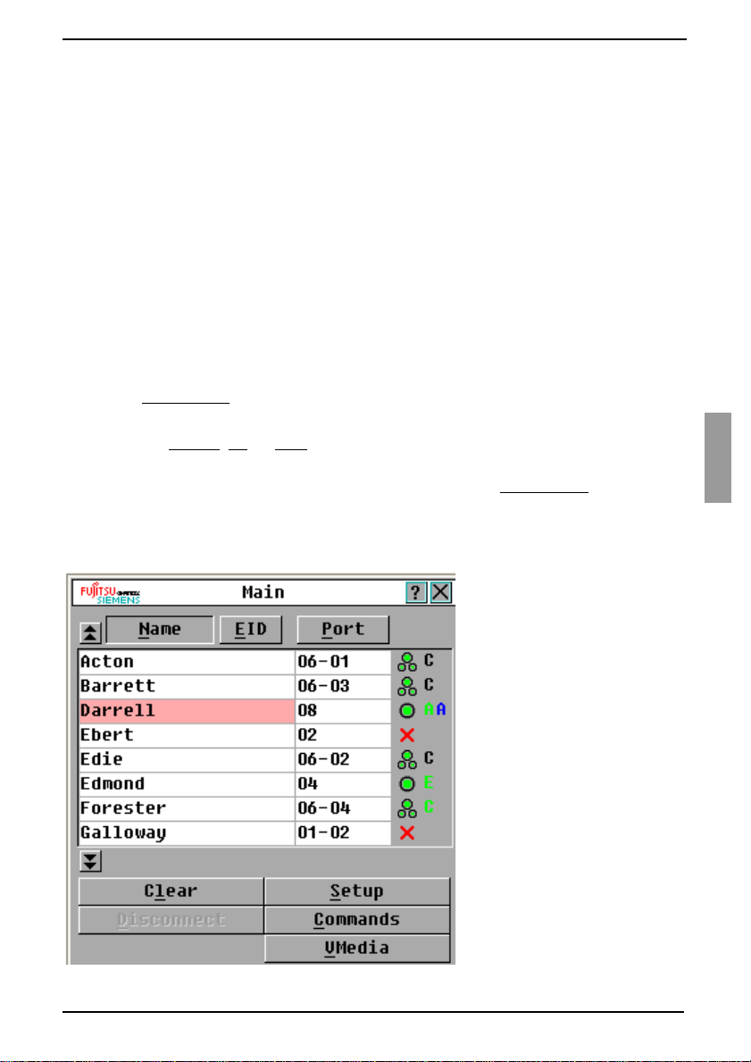
The following illustration is an example of the Main window of the OSCAR interface.
Figure 8: Example of a Main window
Basic operations
18
590-591-609B
The Main window list s the targe t dev ic es in the sw itching system. You can order the li st
by target device names, EID numbers, or port numbers by clicking the Name, EID, or
Port button.
The Port column indicates the ARI port to which each target device is connected. If an
earlier appliance mode l is con nec te d to a KVM s3-1 621 or KVM s 3-16 41 appl ian ce , the
ARI port number is shown first, followed by the number of the appliance port to which
the target device is connected. For example, in Figure 8 on page 17, the target device
named Acton is connected to ARI port 06 and the appliance to port 01.
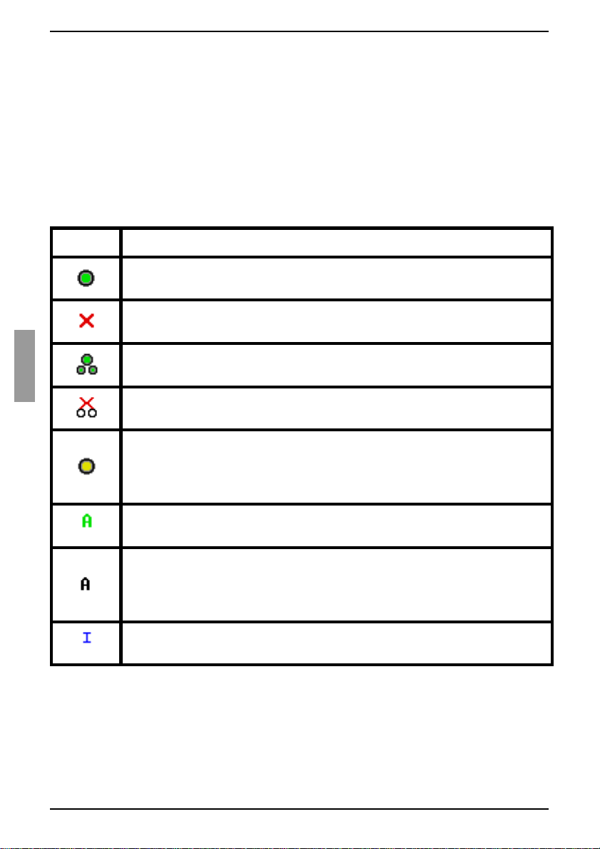
The status of each target device in the switching system is indicated by one or more
status symbols in the right column of the screen. Table 2 describes the status symbols.
Symbol Description
The KVM-IA is online (green circle).
The KVM-IA is offline or is not operating correctly.
The target device is tiered through an earlier appliance model. The target
device and the earlier appliance model is online and has power.
The target device is tiered through an earlier appliance model. The earlier
appliance model is offline or does not have power.
The KVM-IA is being upgrad ed (y el low c ircle). When this symbol is visible,
do not turn off and turn on the appliance or connected target devices and
do not disconnect the KVM-IA. Doing so might damage the KVM-IA
permanently.
The KVM-IA is being accessed by the indicated user channel (green
channel letter).
The KVM-IA is blocked by the indicated user channel (black channel
letter). For instance, in Figure 8 on page 17, user C is viewing Forester,
but is blocking access to Acton, Barrett, and Edie which are connected to
the same KVM-IA.
A virtual media con nec tio n i s e st a bli sh ed to th e target device conne cted to
the indicated user channel (blue letter).
Table 2: OSCAR inter face status symbol s

Setting a screen delay
19
590-591-609B
3.3 Setting a screen delay
You can specify the length of time that elapses between when Print Screen is pressed
and when the OSCAR interface starts.
Press Print Screen
to start the OSCAR interface.
In the Main window, click Setup - Menu.
In the Screen Delay Time field, type the number of seconds that you want to
elapse between when Print Screen is pressed and when the OSCAR interface
starts.
3.4 Conn ecting a user to a target device
Use the Main window of the OSCAR interface to select a target device to which you
want to connect. When you select a target device, the keyboard and mouse are
automatically reconfigured to the correct settings for that target device.
Select a target device by pressing Print Screen
to start the OSCAR interface, and
then use one of the following procedures:
• In the Main window, double-click the target device name, EID number, or port
number.
-or-
• Type the port number, and press Enter
.
-or-
• Type the first few characters of the target device name or EID number, and
press Ente r
.
3.5 Selecting the previously selected
target device
You can toggle between two selected target devices by pressing Print Screen and
then press Backspace
.
3.6 Disconnecting the user from a target device
Press Print Screen and press Alt+0. A Free status flag in the OSCAR interface
indicates that the user is not connected to a target device.
Basic operations
20
590-591-609B
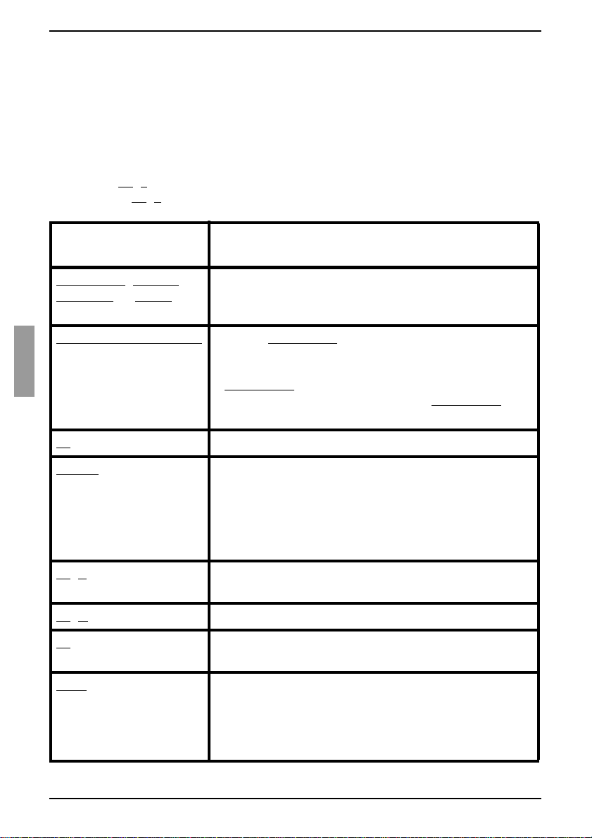
3.7 Using the OSCAR interface
Table 3 describes the keys, key combinations, and mouse actions that you can use in
the OSCAR interface. Two or more key names or mouse actions that are separated by
commas indicate a sequence of actions. Two or more key names or mouse actions that
are separated by a plus sign (+) indicate a combination of actions; that is, they are
performed simultaneously.
You can use the main keyboard or the numeric keypad to type numerals, except when
you use the Alt
+0 key combinat ion; y ou mu st use the 0 (ze ro) key on the main keyb oard
when you use Alt
+0.
Key, key combination,
or mouse action
Result
Print Screen; Ctrl, Ctrl;
Shift, Shift
; or Alt, Alt
Start the OSCAR interface. To specify which key
sequences can be used to start the OSCAR interface,
click Setup - Menu.
Print Screen, Print Screen
Send the Print Screen keystroke to the currently selected
target device. In other words, a screen capture will be
performed for the target device.
If Print Screen
is not selected as st artu p key sequence in
Setup - Menu, you only need to press Print Screen
once
to take a screen capture of the target device.
F1
Display help for the current window.
Escape
In the OSCAR main window: Clos e the OSC AR interf ac e
and return to the status flag on the desktop.
In all other windows: Close the current window, without
saving changes, and return to the previous window.
In pop-up windows: Close the pop-up window and return
to the current window.
Alt
+X Close the current window, without saving changes, and
return to the previous window.
Alt
+O Click OK and return to the previous window.
Alt
+port number Select a target device to be scanned; port number is the
port number of the target device.
Enter
Completes a switch in the Main window and exits the
OSCAR interface.
Click on an editable field to select the text for editing and
enable the Left and Right arrow keys to move the cursor.
Press Enter to quit the edit mode.
Table 3: OSCAR inte rface navigation basics
Connecting local virtual media
21
590-591-609B
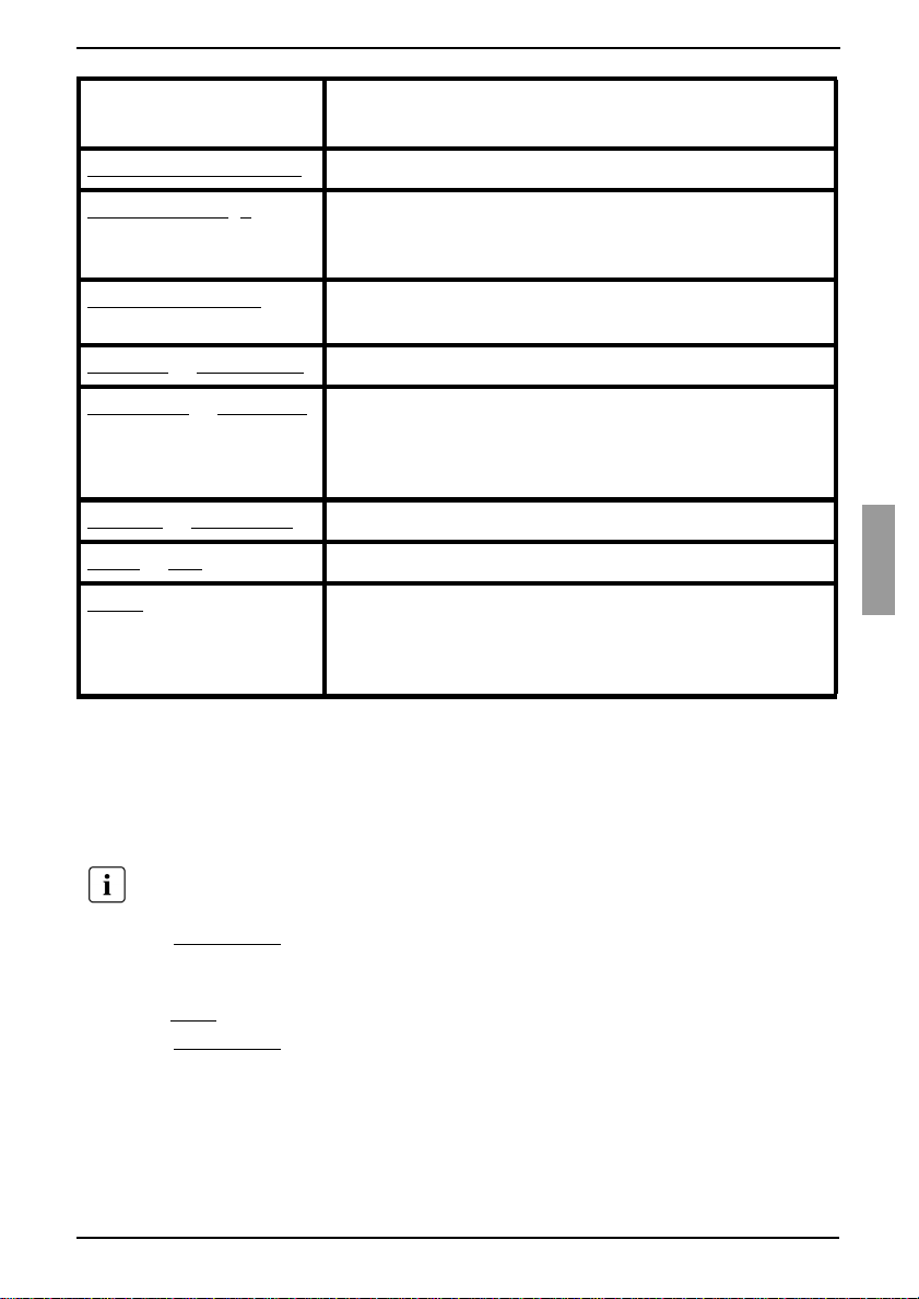
3.8 Connecting local virtual media
You can connect virtual media directly to the KVM s3-1621 and KVM s3-1641
appliances using the USB port on the switches.
Press Print Screen to start the OSCAR interface. The Main window opens.
Connect the user to the target device with which you want to establish a virtual
media session. Use the arrow keys to highlight the target device name, and then
press Ente r
.
Press Print Screen to start the OSCAR interface again. The Virtual Media window
opens.
Print Screen, Backspace R e turn to the previo us ly se lec t ed target dev ic e.
Print Screen, Alt
+0 Disconnect the us er from the selected target device. Note
that the zero must be typed on the main keyboard , not the
numeric keypad.
Print Screen, Pause Start the screen saver immediately and lock the user, if it
is password-protected.
Up Arrow
or Down Arrow Move the cursor from line to line in a list.
Right Arrow
or Left Arro w When editing text in a field: Move within the text in the
field.
All other conditions: Move the cursor from column to
column in a list.
Page Up
or Page Down Page through a list or help window.
Home or End Move the cursor to the top or bottom of a list.
Delete
Delete the selected characters in a field or the selected
item in the scan list. For more information about scan
lists, see section 3.12 Scanning the switchi ng syst em on
page 39.
All USB ports are assigned to a single virtual media session and cannot be
independently mapped.
Key, key combination,
or mouse action
Result
Table 3: OSCAR interface navigation basics (Continued)
Basic operations
22
590-591-609B
Select one or more of the following check boxes:
• Locked - Select this check box to specify that when the user is disconnected
from a target device, the virtual media is also disconnected.
-or-
• Reserve - Select this check box to specify that the virtual media connection
can be accessed on ly by you r user nam e and that no other user can conne ct to
that target device. If both Locked and Reserved are selected, the session will
be reserved.
-or-
• CDROM - Select this c heck box t o estab lish a virtual media CD co nnection to a
target device. Clear this check box to end the connection.
• Mass Storage - Select this check box to establish a virtual media mass-
storage connection to a target device. Clear this check box to end the
connection.
-or-
• Write Access - Sele ct thi s c he ck box to enable the con nec ted ta rget device to
write data to the virtual media during a virtual media session. Read access is
always enabled during virtual media sessions.
Click OK.
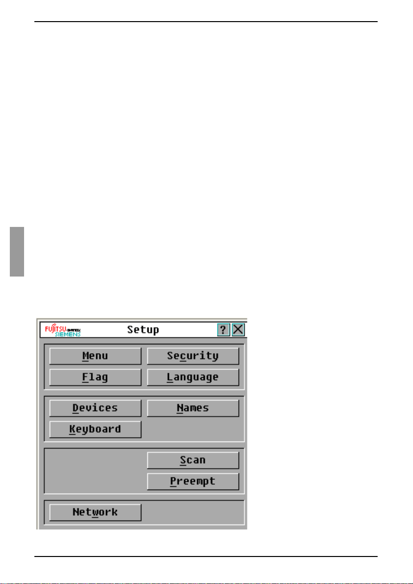
3.9 Configuring the appliances and the
OSCAR interface
Start the OSCAR interface and click Setup. Figure 9 shows the Setup window.
Figure 9: Setup window
Loading...