


 Loading...
SIMATIC NET
Industrial Ethernet Switches
SCALANCE X-200
Operating Instructions
12/2011
___________________
Preface
|
Safety notices |
1 |
|
Network topologies / media |
|
|
2 |
|
|
redundancy |
|
|
|
|
|
Product properties |
3 |
|
|
|
|
Installation |
4 |
|
|
|
|
Connection |
5 |
|
Configuration / diagnostics |
|
|
6 |
|
|
using remote mechanisms |
|
|
IRT technology with |
|
|
7 |
|
|
SCALANCE X-200 |
|
|
|
|
|
PROFINET IO functionality |
8 |
|
|
|
|
Approvals and markings |
9 |
|
|
|
|
Technical specifications |
10 |
|
|
|
|
Accessories |
11 |
|
|
|
______________ |
|
|
12 |
||
|
References |
|
|
|
|
|
Dimension drawings |
13 |
|
|
|
A5E00349864-19

Legal information
Warning notice system
This manual contains notices you have to observe in order to ensure your personal safety, as well as to prevent damage to property. The notices referring to your personal safety are highlighted in the manual by a safety alert symbol, notices referring only to property damage have no safety alert symbol. These notices shown below are graded according to the degree of danger.
 DANGER
indicates that death or severe personal injury will result if proper precautions are not taken.
 WARNING
indicates that death or severe personal injury may result if proper precautions are not taken.
 CAUTION
with a safety alert symbol, indicates that minor personal injury can result if proper precautions are not taken.
CAUTION
without a safety alert symbol, indicates that property damage can result if proper precautions are not taken.
NOTICE
indicates that an unintended result or situation can occur if the relevant information is not taken into account.
If more than one degree of danger is present, the warning notice representing the highest degree of danger will be used. A notice warning of injury to persons with a safety alert symbol may also include a warning relating to property damage.
Qualified Personnel
The product/system described in this documentation may be operated only by personnel qualified for the specific task in accordance with the relevant documentation, in particular its warning notices and safety instructions. Qualified personnel are those who, based on their training and experience, are capable of identifying risks and avoiding potential hazards when working with these products/systems.
Proper use of Siemens products
Note the following:
 WARNING
Siemens products may only be used for the applications described in the catalog and in the relevant technical documentation. If products and components from other manufacturers are used, these must be recommended or approved by Siemens. Proper transport, storage, installation, assembly, commissioning, operation and maintenance are required to ensure that the products operate safely and without any problems. The permissible ambient conditions must be complied with. The information in the relevant documentation must be observed.
Trademarks
All names identified by ® are registered trademarks of Siemens AG. The remaining trademarks in this publication may be trademarks whose use by third parties for their own purposes could violate the rights of the owner.
Disclaimer of Liability
We have reviewed the contents of this publication to ensure consistency with the hardware and software described. Since variance cannot be precluded entirely, we cannot guarantee full consistency. However, the information in this publication is reviewed regularly and any necessary corrections are included in subsequent editions.
Siemens AG |
Order number: A5E00349864-19 |
Copyright © Siemens AG 2011. |
Industry Sector |
12/2011 Technical data subject to change |
All rights reserved |
Postfach 48 48 |
|
|
90026 NÜRNBERG |
|
|
GERMANY |
|
|
Preface
Overview of the SCALANCE X product family
The SCALANCE X-200 product family is part of the SCALANCE X product family. Below, you will find a brief overview of this product family.
The SCALANCE X family comprises various product lines that complement each other and that are carefully tuned to specific automation tasks.
SCALANCE X005 and XB000 line, entry level
Unmanaged switch with five twisted-pair ports and optical diagnostics on the device for use in machine and system islands.
SCALANCE X-100 unmanaged
Switches with redundant power supply and signaling contact for use in applications in the immediate vicinity of machinery.
A variety of device variants with different numbers and designs of electrical and optical ports.
SCALANCE X-200 and XF-200 managed
The devices of the SCALANCE X-200 product line can be used universally – in machinelevel applications as well as in networked plant sections, in electrical or electrical/optical linear, ring or star structures and with single mode up to 26 km.
Devices with a high degree of protection (IP65/67) can be installed outside the control cabinet.
Configuration and remote diagnostics functions are integrated in the STEP 7 engineering tool. This increases plant availability and has advantages during the engineering, commissioning and operational phases. The devices of the SCALANCE X-200 line also have standard remote diagnostics functions (SNMP, Web server).
The only difference between the devices of the SCALANCE XF-200 product line and the SCALANCE X-200 product is the flatter construction.
SCALANCE X-200IRT and XF204IRT managed
In subsystem networks with hard real-time requirements (real time and isochronous real time), the SCALANCE X-200IRT switches can be used. They include the enhanced real-time controller ERTEC. By using the "cut through" switching mechanism, the switches are ideal to meet the real-time requirements of PROFINET.
The standard data transmission (TCP/IP) can take place on the same network. Dual network structures are therefore not necessary.
Network installation, configuration and diagnostics involves the same procedures as for the other devices of the SCALANCE X-200 product line.
SCALANCE X-200 |
|
Operating Instructions, 12/2011, A5E00349864-19 |
3 |

Preface
The only difference between the SCALANCE XF204IRT and the SCALANCE X-204IRT is the shape.
SCALANCE X-200 IRT PRO managed
In terms of functionality, the SCALANCE X200 IRT PRO switches are the same as the SCALANCE X-200 IRT managed switches listed above. The switch with degree of protection IP65/IP67 is designed for use outside a cabinet and has PROFINET-compliant connector technology (RJ-45 in compliance with IEC 61076-3-117 for X204 IRT PRO or SC RJ in compliance with IEC 61754-24-2 for X202-2P IRT PRO).
SCALANCE X-300
The main areas of application are high-speed plant networks with an interface to the Enterprise network. The SCALANCE X-300 managed plus product line combines the firmware functionality of the SCALANCE X-400 product line (without routing functions at the layer 3 level) with the compact design of the SCALANCE X-200 product line. The "managed plus" attribute means both enhanced management functions compared with the SCALANCE X-200 and enhanced firmware functionality.
SCALANCE X-400 modular
The switches of the SCALANCE X-400 product series are suitable for the construction of optical/electrical linear, ring and star topologies (10/100/1000 Mbps) for high-speed systems.
They have a modular structure, in which media modules and extender modules can be inserted in the switch as required. These expansions make as many as eight electrical and eight optical ports additionally available.
By supporting IT standards, for example, VLAN, RSTP, Layer 3, automation networks can be seamlessly connected to existing corporate networks.
The SCALANCE X-400 switches are ideally suited, for example, for process control systems such as PCS 7.
What is possible?
The devices of the SCALANCE X-200 product lines allow the cost-effective installation of Industrial Ethernet linear (bus), star and ring structures with switching functionality.
By using the “cut through” switching mechanism, the SCALANCE X-200IRT switches are ideal to meet the real-time requirements of PROFINET.
Cut through is not possible
●between a port set to 10 Mbps and a port set to 100 Mbps
●when two packets are to be sent at the same time on one port.
|
SCALANCE X-200 |
4 |
Operating Instructions, 12/2011, A5E00349864-19 |

Preface
One particular advantage of the SCALANCE X-200IRT switches in PROFINET networks is the integrated ERTEC. This gives priority to PROFINET packets when forwarding.
 WARNING
When used under hazardous conditions (zone 2), the devices of the SCALANCE X-100 and SCALANCE X-200 product lines must be installed in an enclosure.
To comply with ATEX95 (EN 60079-15), this enclosure must meet the requirements of at least IP54 in compliance with EN 60529.
WARNING – EXPLOSION HAZARD: DO NOT DISCONNECT EQUIPMENT WHEN A FLAMMABLE OR COMBUSTIBLE ATMOSPHERE IS PRESENT.
Note
The specified approvals apply only when the corresponding mark is printed on the product.
Purpose of the Operating Instructions
These operating instructions support you when commissioning networks with the devices of the product line SCALANCE X-200.
Validity of the Operating Instructions
These operating instructions are valid for the following devices:
|
SIMATIC NET SCALANCE XF204 |
6GK5204-0BA00-2AF2 |
|
SIMATIC NET SCALANCE X208 |
6GK5208-0BA10-2AA3 |
|
SIMATIC NET SCALANCE XF208 |
6GK5208-0BA00-2AF2 |
|
SIMATIC NET SCALANCE X216 |
6GK5216-0BA00-2AA3 |
|
SIMATIC NET SCALANCE X224 |
6GK5224-0BA00-2AA3 |
|
SIMATIC NET SCALANCE X204-2 |
6GK5204-2BB10-2AA3 |
|
SIMATIC NET SCALANCE X204-2TS |
6GK5204-2BB10-2CA2 |
|
SIMATIC NET SCALANCE XF204-2 |
6GK5204-2BC00-2AF2 |
|
SIMATIC NET SCALANCE X206-1 |
6GK5206-1BB10-2AA3 |
|
SIMATIC NET SCALANCE XF206-1 |
6GK5206-1BC00-2AF2 |
|
SIMATIC NET SCALANCE X212-2 |
6GK5212-2BB00-2AA3 |
|
SIMATIC NET SCALANCE X204-2LD |
6GK5204-2BC10-2AA3 |
|
SIMATIC NET SCALANCE X206-1LD |
6GK5206-1BC10-2AA3 |
|
SIMATIC NET SCALANCE X212-2LD |
6GK5212-2BC00-2AA3 |
|
SIMATIC NET SCALANCE X202-2IRT |
6GK5202-2BB00-2BA3 |
|
SIMATIC NET SCALANCE X204IRT |
6GK5204-0BA00-2BA3 |
|
SIMATIC NET SCALANCE XF204IRT |
6GK5204-0BA00-2BF2 |
|
SIMATIC NET SCALANCE X204 IRT PRO |
6GK5204-0JA00-2BA6 |
|
SIMATIC NET SCALANCE X202-2P IRT PRO |
6GK5202-2JR00-2BA6 |
SCALANCE X-200 |
|
|
Operating Instructions, 12/2011, A5E00349864-19 |
5 |
|

Preface
SIMATIC NET SCALANCE X201-3P IRT PRO |
6GK5201-3JR00-2BA6 |
SIMATIC NET SCALANCE X202-2P IRT |
6GK5202-2BH00-2BA3 |
SIMATIC NET SCALANCE X201-3P IRT |
6GK5201-3BH00-2BA3 |
SIMATIC NET SCALANCE X200-4P IRT |
6GK5200-4AH00-2BA3 |
Names of the devices in these operating instructions
The descriptions in these operating instructions always apply to the devices of the SCALANCE X-200 product line listed under "Validity of the Operating Instructions" in this document unless the description relates to a specific device of the product line. In the remainder of the description, the devices are called IE Switch X-200 or X-200 IE switches.
Further documentation
The "SIMATIC NET Industrial Ethernet Twisted Pair and Fiber Optic Networks" manual contains additional information on other SIMATIC NET products that you can operate along with the devices of the SCALANCE X-200 product line in an Industrial Ethernet network.
Finding information
To help you to find the information you require more quickly, the manual includes not only the table of contents but also the following sections in the Appendix:
●Index
●Glossary
Audience
These operating instructions are intended for persons involved in commissioning networks in which IE switches are used.
Standards and approvals
The devices of the SCALANCE X-200 product line meet the requirements for the CE mark. You will find detailed information in the section "Approvals and markings" in these operating instructions.
SIMATIC NET glossary
Explanations of the specialist terms used in this documentation can be found in the SIMATIC NET glossary.
You will find the SIMATIC NET glossary here:
●SIMATIC NET Manual DVD
The DVD ships with most SIMATIC NET products.
●On the Internet under the following entry ID:
50305045 (http://support.automation.siemens.com/WW/view/en/50305045)
|
SCALANCE X-200 |
6 |
Operating Instructions, 12/2011, A5E00349864-19 |
Table of contents
|
Preface...................................................................................................................................................... |
|
3 |
1 |
Safety notices.......................................................................................................................................... |
13 |
|
|
1.1 |
Important notes on using the device............................................................................................ |
13 |
2 |
Network topologies / media redundancy.................................................................................................. |
17 |
|
|
2.1 |
Network topologies ...................................................................................................................... |
17 |
|
2.2 |
Options of media redundancy...................................................................................................... |
22 |
|
2.3 |
Media redundancy in ring topologies........................................................................................... |
23 |
|
2.4 |
MRP............................................................................................................................................. |
25 |
|
2.5 |
MRPD........................................................................................................................................... |
27 |
|
2.6 |
HSR.............................................................................................................................................. |
28 |
|
2.7 |
Redundant coupling of network segments................................................................................... |
29 |
3 |
Product properties ................................................................................................................................... |
31 |
|
|
3.1 |
Overview of the product characteristics....................................................................................... |
31 |
|
3.2 |
Components of the product.......................................................................................................... |
33 |
|
3.3 |
Unpacking and checking.............................................................................................................. |
34 |
|
3.4 |
SCALANCE XF204...................................................................................................................... |
35 |
|
3.4.1 |
SCALANCE XF204 product characteristics................................................................................. |
35 |
|
3.4.2 |
SCALANCE XF204 TP ports ....................................................................................................... |
36 |
|
3.5 |
SCALANCE X208........................................................................................................................ |
38 |
|
3.5.1 |
SCALANCE X208 product characteristics................................................................................... |
38 |
|
3.5.2 |
SCALANCE X208 TP ports.......................................................................................................... |
39 |
|
3.6 |
SCALANCE XF208...................................................................................................................... |
41 |
|
3.6.1 |
SCALANCE XF208 product characteristics................................................................................. |
41 |
|
3.6.2 |
SCALANCE XF208 TP ports ....................................................................................................... |
42 |
|
3.7 |
SCALANCE X216........................................................................................................................ |
44 |
|
3.7.1 |
SCALANCE X216 product characteristics................................................................................... |
44 |
|
3.7.2 |
SCALANCE X216 TP ports.......................................................................................................... |
45 |
|
3.8 |
SCALANCE X224........................................................................................................................ |
47 |
|
3.8.1 |
SCALANCE X224 product characteristics................................................................................... |
47 |
|
3.8.2 |
SCALANCE X224 TP ports.......................................................................................................... |
48 |
|
3.9 |
SCALANCE X204-2 / SCALANCE X204-2TS............................................................................. |
50 |
|
3.9.1 |
SCALANCE X204-2 / SCALANCE X204-2TS product features.................................................. |
50 |
|
3.9.2 |
SCALANCE X204-2 / SCALANCE X204-2TS TP interfaces....................................................... |
51 |
|
3.9.3 |
SCALANCE X204-2 / SCALANCE X204-2TS FO interfaces ...................................................... |
53 |
|
3.10 |
SCALANCE XF204-2................................................................................................................... |
54 |
|
3.10.1 |
SCALANCE XF204-2 product characteristics.............................................................................. |
54 |
SCALANCE X-200 |
|
|
|
Operating Instructions, 12/2011, A5E00349864-19 |
7 |
||

Table of contents
3.10.2 |
SCALANCE XF204-2 TP ports................................................................................................... |
55 |
3.10.3 |
SCALANCE XF204-2 FO ports................................................................................................... |
57 |
3.11 |
SCALANCE X206-1.................................................................................................................... |
58 |
3.11.1 |
SCALANCE X206-1 product characteristics............................................................................... |
58 |
3.11.2 |
SCALANCE X206-1 TP ports ..................................................................................................... |
59 |
3.11.3 |
SCALANCE X206-1 FO ports..................................................................................................... |
61 |
3.12 |
SCALANCE XF206-1.................................................................................................................. |
62 |
3.12.1 |
SCALANCE XF206-1 product characteristics............................................................................. |
62 |
3.12.2 |
SCALANCE XF206-1 TP ports................................................................................................... |
63 |
3.12.3 |
SCALANCE XF206-1 FO ports................................................................................................... |
65 |
3.13 |
SCALANCE X212-2.................................................................................................................... |
66 |
3.13.1 |
SCALANCE X212-2 product characteristics............................................................................... |
66 |
3.13.2 |
SCALANCE X212-2 TP ports ..................................................................................................... |
67 |
3.13.3 |
SCALANCE X212-2 FO ports..................................................................................................... |
69 |
3.14 |
SCALANCE X204-2LD................................................................................................................ |
70 |
3.14.1 |
SCALANCE X204-2LD product characteristics.......................................................................... |
70 |
3.14.2 |
SCALANCE X204-2LD TP ports................................................................................................. |
71 |
3.14.3 |
SCALANCE X204-2LD TP ports................................................................................................. |
73 |
3.15 |
SCALANCE X206-1LD................................................................................................................ |
75 |
3.15.1 |
SCALANCE X206-1LD product characteristics.......................................................................... |
75 |
3.15.2 |
SCALANCE X206-1LD TP ports................................................................................................. |
76 |
3.15.3 |
SCALANCE X206-1LD FO ports ................................................................................................ |
78 |
3.16 |
SCALANCE X212-2LD................................................................................................................ |
80 |
3.16.1 |
SCALANCE X212-2LD product characteristics.......................................................................... |
80 |
3.16.2 |
SCALANCE X212-2LD TP ports................................................................................................. |
81 |
3.16.3 |
SCALANCE X212-2LD FO ports ................................................................................................ |
83 |
3.17 |
SCALANCE X202-2IRT .............................................................................................................. |
85 |
3.17.1 |
SCALANCE X202-2IRT product characteristics......................................................................... |
85 |
3.17.2 |
SCALANCE X202-2IRT TP ports................................................................................................ |
86 |
3.17.3 |
SCALANCE X202-2IRT FO ports............................................................................................... |
88 |
3.18 |
SCALANCE X204IRT.................................................................................................................. |
89 |
3.18.1 |
SCALANCE X204IRT product characteristics............................................................................ |
89 |
3.18.2 |
SCALANCE X204IRT TP ports................................................................................................... |
90 |
3.19 |
SCALANCE XF204IRT ............................................................................................................... |
92 |
3.19.1 |
SCALANCE XF204IRT product characteristics.......................................................................... |
92 |
3.19.2 |
SCALANCE XF204IRT TP ports................................................................................................. |
93 |
3.20 |
SCALANCE X204 IRT PRO........................................................................................................ |
95 |
3.20.1 |
SCALANCE X204 IRT PRO product characteristics .................................................................. |
95 |
3.20.2 |
SCALANCE X204 IRT PRO TP ports......................................................................................... |
96 |
3.21 |
SCALANCE X202-2P IRT PRO.................................................................................................. |
98 |
3.21.1 |
SCALANCE X202-2P IRT PRO product characteristics............................................................. |
98 |
3.21.2 |
SCALANCE X202-2P IRT PRO TP ports ................................................................................... |
99 |
3.21.3 |
SCALANCE X202-2P IRT PRO FO ports................................................................................. |
101 |
3.22 |
SCALANCE X201-3P IRT PRO................................................................................................ |
102 |
3.22.1 |
SCALANCE X201-3P IRT PRO product characteristics........................................................... |
102 |
3.22.2 |
SCALANCE X201-3P IRT PRO TP interfaces.......................................................................... |
103 |
|
|
SCALANCE X-200 |
8 |
|
Operating Instructions, 12/2011, A5E00349864-19 |

Table of contents
|
3.22.3 |
SCALANCE X201-3P IRT PRO FO interfaces.......................................................................... |
105 |
|
3.23 |
SCALANCE X202-2P IRT.......................................................................................................... |
106 |
|
3.23.1 |
SCALANCE X202-2P IRT product characteristics..................................................................... |
106 |
|
3.23.2 |
SCALANCE X202-2P IRT TP ports........................................................................................... |
107 |
|
3.23.3 |
SCALANCE X202-2P IRT FO ports........................................................................................... |
109 |
|
3.24 |
SCALANCE X201-3P IRT.......................................................................................................... |
110 |
|
3.24.1 |
SCALANCE X201-3P IRT product characteristics..................................................................... |
110 |
|
3.24.2 |
SCALANCE X201-3P IRT TP ports........................................................................................... |
111 |
|
3.24.3 |
SCALANCE X201-3P IRT FO ports........................................................................................... |
113 |
|
3.25 |
SCALANCE X200-4P IRT.......................................................................................................... |
114 |
|
3.25.1 |
SCALANCE X200-4P IRT product characteristics..................................................................... |
114 |
|
3.25.2 |
SCALANCE X200-4P IRT FO ports........................................................................................... |
115 |
|
3.26 |
C-PLUG (configuration plug)...................................................................................................... |
116 |
|
3.27 |
Button......................................................................................................................................... |
119 |
|
3.28 |
Displays...................................................................................................................................... |
120 |
|
3.28.1 |
Fault indicator (red LED)............................................................................................................ |
120 |
|
3.28.2 |
Power display............................................................................................................................. |
121 |
|
3.28.3 |
Port status indicator (green/yellow LEDs).................................................................................. |
123 |
|
3.28.4 |
Redundancy manager indicator (green LED)............................................................................ |
124 |
|
3.28.5 |
Standby functions (yellow LED)................................................................................................. |
125 |
|
3.28.6 |
FOC diagnostic display (yellow LED) ........................................................................................ |
126 |
|
3.28.7 |
LED display during startup......................................................................................................... |
127 |
4 |
Installation ............................................................................................................................................. |
129 |
|
|
4.1 |
Installation.................................................................................................................................. |
129 |
|
4.2 |
Installation on a DIN rail............................................................................................................. |
131 |
|
4.3 |
Installation on a standard rail..................................................................................................... |
132 |
|
4.4 |
Wall mounting ............................................................................................................................ |
133 |
5 |
Connection ............................................................................................................................................ |
135 |
|
|
5.1 |
Power supply.............................................................................................................................. |
135 |
|
5.2 |
Signaling contact........................................................................................................................ |
140 |
|
5.3 |
Grounding .................................................................................................................................. |
142 |
|
5.4 |
Fitting the IE FC RJ-45 Plug 180............................................................................................... |
143 |
|
5.5 |
Fitting the IE RJ 45 Plug Pro and IE SC RJ Plug Pro................................................................ |
145 |
6 |
Configuration / diagnostics using remote mechanisms.......................................................................... |
147 |
|
|
6.1 |
Assignment of an IP address..................................................................................................... |
147 |
|
6.1.1 |
Introduction ................................................................................................................................ |
147 |
|
6.1.2 |
Configuration with the Primary Setup Tool................................................................................ |
147 |
|
6.1.2.1 |
Configuration with the Primary Setup Tool................................................................................ |
147 |
|
6.1.2.2 |
Installing the Primary Setup Tool............................................................................................... |
148 |
|
6.1.2.3 |
The DLC protocol....................................................................................................................... |
149 |
|
6.1.2.4 |
Installing the DLC protocol......................................................................................................... |
150 |
|
6.1.2.5 |
Working with the Primary Setup Tool ........................................................................................ |
150 |
|
6.1.2.6 |
Configuring a module................................................................................................................. |
151 |
SCALANCE X-200 |
|
|
|
Operating Instructions, 12/2011, A5E00349864-19 |
9 |
||

Table of contents
|
6.1.3 |
Configuration with DHCP.......................................................................................................... |
154 |
|
6.2 |
Updating the firmware with the boot loader .............................................................................. |
155 |
|
6.3 |
Configuration using Web Based Management (WBM) and Command Line Interface (CLI).... 156 |
|
|
6.3.1 |
Principle of Web Based Management....................................................................................... |
157 |
|
6.3.2 |
LED simulation.......................................................................................................................... |
159 |
|
6.3.3 |
Working with WBM.................................................................................................................... |
159 |
|
6.3.4 |
Command Line Interface (CLI).................................................................................................. |
161 |
|
6.3.5 |
WBM menus.............................................................................................................................. |
163 |
|
6.3.5.1 |
Management menus - the Start menu ...................................................................................... |
163 |
|
6.3.5.2 |
The "System" WBM menu......................................................................................................... |
164 |
|
6.3.5.3 |
"System C-PLUG" WBM menu................................................................................................. |
166 |
|
6.3.5.4 |
The "System I&M" WBM menu................................................................................................. |
169 |
|
6.3.5.5 |
The "System Restart & Defaults" WBM menu.......................................................................... |
170 |
|
6.3.5.6 |
The "System Save & Load HTTP" WBM menu ........................................................................ |
172 |
|
6.3.5.7 |
The "System Save & Load TFTP" WBM menu......................................................................... |
174 |
|
6.3.5.8 |
The "System Version Numbers" WBM menu............................................................................ |
177 |
|
6.3.5.9 |
The "System Passwords" WBM menu...................................................................................... |
179 |
|
6.3.5.10 |
The "System Select/Set Button" WBM menu............................................................................ |
180 |
|
6.3.5.11 |
The "System Event Log" WBM menu....................................................................................... |
180 |
|
6.3.5.12 |
The "X200" WBM menu............................................................................................................ |
182 |
|
6.3.5.13 |
The "X200 Fault Mask" WBM menu ......................................................................................... |
183 |
|
6.3.5.14 |
The "X200 Ring" WBM menu.................................................................................................... |
185 |
|
6.3.5.15 |
The "X200 Standby" WBM menu.............................................................................................. |
190 |
|
6.3.5.16 |
The "Agent" WBM menu........................................................................................................... |
192 |
|
6.3.5.17 |
The "Ping" WBM menu ............................................................................................................. |
194 |
|
6.3.5.18 |
The "Agent SNMP Config" WBM menu.................................................................................... |
195 |
|
6.3.5.19 |
The "Agent SNMP Trap Config" WBM menu............................................................................ |
197 |
|
6.3.5.20 |
The "Agent SNMP Config Groups" WBM menu ....................................................................... |
198 |
|
6.3.5.21 |
The "Agent SNMP Config Group Table" WBM menu............................................................... |
200 |
|
6.3.5.22 |
The "Agent SNMP Config Users" WBM menu.......................................................................... |
202 |
|
6.3.5.23 |
The "Agent SNMP Config User Table" WBM menu.................................................................. |
203 |
|
6.3.5.24 |
The "Agent Event Config" WBM menu ..................................................................................... |
204 |
|
6.3.5.25 |
The "Agent E-Mail Config" WBM menu .................................................................................... |
207 |
|
6.3.5.26 |
The "Agent Time Config" WBM menu....................................................................................... |
209 |
|
6.3.5.27 |
The "Switch" WBM menu.......................................................................................................... |
211 |
|
6.3.5.28 |
The "Switch Ports" WBM menu................................................................................................. |
213 |
|
6.3.5.29 |
The "Switch Port Diags" WBM menu........................................................................................ |
216 |
|
6.3.5.30 |
The "Switch FDB" WBM menu.................................................................................................. |
217 |
|
6.3.5.31 |
The "Switch ARP Table" WBM menu ....................................................................................... |
219 |
|
6.3.5.32 |
The "Switch LLDP" WBM menu................................................................................................ |
219 |
|
6.3.5.33 |
The "Switch DCP" WBM menu ................................................................................................. |
222 |
|
6.3.5.34 |
The "Switch POF" WBM menu.................................................................................................. |
224 |
|
6.3.5.35 |
The "Loop Detection Config" WBM menu................................................................................. |
226 |
|
6.3.5.36 |
The "Statistics" WBM menu...................................................................................................... |
230 |
|
6.3.5.37 |
The "Statistics Packet Size" WBM menu.................................................................................. |
232 |
|
6.3.5.38 |
The "Statistics Packet Type" WBM menu................................................................................. |
234 |
|
6.3.5.39 |
The "Statistics Packet Error" WBM menu................................................................................. |
236 |
|
6.3.6 |
SNMP........................................................................................................................................ |
238 |
|
6.3.6.1 |
Configuration and diagnostics over SNMP............................................................................... |
238 |
|
6.3.6.2 |
MIB variables ............................................................................................................................ |
239 |
7 |
IRT technology with SCALANCE X-200................................................................................................. |
243 |
|
|
|
|
SCALANCE X-200 |
10 |
|
|
Operating Instructions, 12/2011, A5E00349864-19 |
Table of contents
8 |
PROFINET IO functionality.................................................................................................................... |
245 |
|
|
8.1 |
Configuring with PROFINET IO................................................................................................. |
245 |
|
8.2 |
Settings in HW Config................................................................................................................ |
249 |
|
8.2.1 |
Configuring alarms..................................................................................................................... |
249 |
|
8.2.2 |
Configuring MRP........................................................................................................................ |
250 |
|
8.2.3 |
Configuring the topology............................................................................................................ |
254 |
|
8.3 |
HSR configuration in PROFINET IO.......................................................................................... |
256 |
|
8.4 |
Structure of the data records ..................................................................................................... |
257 |
9 |
Approvals and markings........................................................................................................................ |
263 |
|
10 |
Technical specifications......................................................................................................................... |
275 |
|
11 |
Accessories........................................................................................................................................... |
285 |
|
12 |
References............................................................................................................................................ |
287 |
|
13 |
Dimension drawings .............................................................................................................................. |
289 |
|
|
Index |
...................................................................................................................................................... |
295 |
SCALANCE X-200 |
|
Operating Instructions, 12/2011, A5E00349864-19 |
11 |

Table of contents
|
SCALANCE X-200 |
12 |
Operating Instructions, 12/2011, A5E00349864-19 |

Safety notices |
1 |
1.1Important notes on using the device
Safety notices on the use of the devices
The following safety notices must be adhered to when setting up and operating the device and during all work relating to it such as installation, connecting up, replacing devices or opening the device.
General notices
 WARNING Safety extra low voltage
The equipment is designed for operation with Safety Extra-Low Voltage (SELV) by a Limited Power Source (LPS). (This does not apply to 100 V...240 V devices.)
This means that only SELV / LPS complying with IEC 60950-1 / EN 60950-1 / VDE 0805-1 must be connected to the power supply terminals. The power supply unit for the equipment power supply must comply with NEC Class 2, as described by the National Electrical Code
(r) (ANSI / NFPA 70).
There is an additional requirement if devices are operated with a redundant power supply:
If the equipment is connected to a redundant power supply (two separate power supplies), both must meet these requirements.
 WARNING
Opening the device
DO NOT OPEN WHEN ENERGIZED.
General notices on use in hazardous areas
 WARNING
Risk of explosion when connecting or disconnecting the device
EXPLOSION HAZARD
DO NOT CONNECT OR DISCONNECT EQUIPMENT WHEN A FLAMMABLE OR
COMBUSTIBLE ATMOSPHERE IS PRESENT.
SCALANCE X-200 |
|
Operating Instructions, 12/2011, A5E00349864-19 |
13 |

Safety notices
1.1 Important notes on using the device
 WARNING
Replacing components EXPLOSION HAZARD
SUBSTITUTION OF COMPONENTS MAY IMPAIR SUITABILITY FOR CLASS I, DIVISION 2 OR ZONE 2.
 WARNING
Requirements for the cabinet/enclosure
When used in hazardous environments corresponding to Class I, Division 2 or Class I, Zone 2, the device must be installed in a cabinet or a suitable enclosure.
 WARNING
WARNING - EXPLOSION HAZARD -
DO NOT DISCONNECT WHILE CIRCUIT IS LIVE UNLESS AREA IS KNOWN TO BE NON-HAZARDOUS.
 WARNING
Restricted area of application
This equipment is suitable for use in Class I, Division 2, Groups A, B, C and D or nonhazardous locations only.
 WARNING
Restricted area of application
This equipment is suitable for use in Class I, Zone 2, Group IIC or non-hazardous locations only.
General notices on use in hazardous areas according to ATEX
 WARNING
Requirements for the cabinet/enclosure
To comply with EU Directive 94/9 (ATEX95), this enclosure must meet the requirements of at least IP54 in compliance with EN 60529.
The fiber-optic bus connections labeled SCALANCE X-200/XF-200 (see type plate) may also be led through a hazardous area zone1 (see also Approvals and markings (Page 263), section "Explosion Protection Directive (ATEX)").
|
SCALANCE X-200 |
14 |
Operating Instructions, 12/2011, A5E00349864-19 |

Safety notices
1.1 Important notes on using the device
 WARNING
Suitable cables for temperatures in excess of 70 °C
If the cable or conduit entry point exceeds 70 °C or the branching point of conductors exceeds 80 °C, special precautions must be taken. If the equipment is operated in an air ambient in excess of 50 °C to 70 °C, only use cables with admitted maximum operating temperature of at least 80 °C.
 WARNING
Protection against transient voltage surges
Provisions shall be made to prevent the rated voltage from being exceeded by transient voltage surges of more than 40%. This criterion is fulfilled, if supplies are derived from SELV (Safety Extra-Low Voltage) only.
See also
Approvals and markings (Page 263)
SCALANCE X-200 |
|
Operating Instructions, 12/2011, A5E00349864-19 |
15 |

Safety notices
1.1 Important notes on using the device
|
SCALANCE X-200 |
16 |
Operating Instructions, 12/2011, A5E00349864-19 |
Network topologies / media redundancy |
2 |
2.1Network topologies
Switching technology allows extensive networks to be set up with numerous nodes and simplifies network expansion.
Which topologies can be implemented?
Bus, ring, or star topologies can be implemented with the X-200 IE switches.
Note
Make sure that the maximum permitted cable lengths for the relevant devices are not exceeded. You will find the permitted cable lengths in the technical specifications.
For example, with the SCALANCE X202-2P IRT, X201-3P IRT, X200P IRT, X202-2P IRT PRO and X201-3P IRT PRO only 50 m POF or 100 m HCS cable may be used.
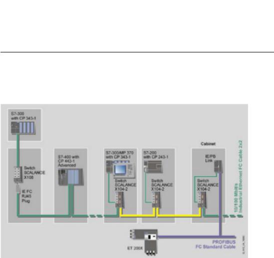
Bus topology
Figure 2-1 Electrical / optical linear topology with SCALANCE X-100
SCALANCE X-200 |
|
Operating Instructions, 12/2011, A5E00349864-19 |
17 |
Network topologies /media redundancy
2.1 Network topologies
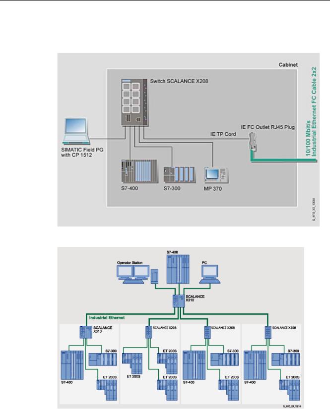
Star topology
Figure 2-2 Electrical star topology. Example with SCALANCE X208
Figure 2-3 Star topology with X310 and X208
|
SCALANCE X-200 |
18 |
Operating Instructions, 12/2011, A5E00349864-19 |
Network topologies /media redundancy
2.1 Network topologies
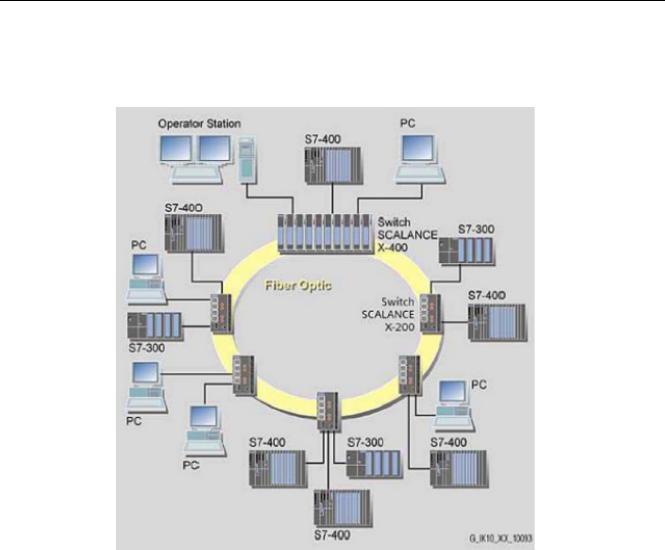
Ring topology
Figure 2-4 Optical ring topology, example with SCALANCE X-200 and SCALANCE X-400 as redundancy manager
SCALANCE X-200 |
|
Operating Instructions, 12/2011, A5E00349864-19 |
19 |

Network topologies /media redundancy
2.1 Network topologies
Operator Station
S7-400
PC
S7-300 |
PC
S7-400
Switch |
S7-300 |
|
SCALANCE |
||
|
||
X-400 |
|
Twisted Pair |
|
S7-400 |
|
Switch |
|
|
|
|
|
SCALANCE |
|
|
X208 |
|
 PC
PC
PC
S7-400 |
S7-300 |
S7-400 |
PC
S7-400 |
G_IK10_XX_10101 |
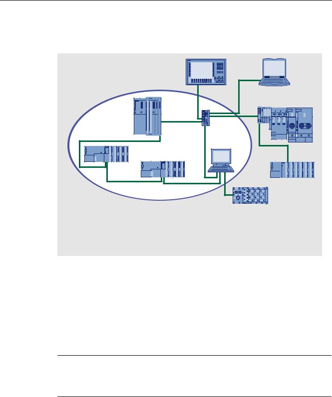
Figure 2-5 Electrical ring topology, example with SCALANCE X208 and SCALANCE X-400 as redundancy manager
Figure 2-6 Ring topology with electrical and optical ring links, example with SCALANCE X206-1, SCALANCE X208, and SCALANCE X204-2 as redundancy manager
SCALANCE X-200
20 |
Operating Instructions, 12/2011, A5E00349864-19 |
Network topologies /media redundancy
2.1 Network topologies
Figure 2-7 Ring topology with optical ring, example with SCALANCE X202-2IRT
To increase availability, optical or electrical bus topologies made up of X-200 IE Switches with an IE Switch X-200, IE Switch X-300, SCALANCE X414-3E, OSM version 2 or ESM version 2 configured as a redundancy manager can be closed to form a ring. The
IE Switches X-200 are first connected over their ring ports to form a bus. The two ends of the bus are closed to form a ring by a switch operating in the redundancy manager mode. Devices of the IE switches X-200, X-300, X-400 product families, or OSMs / ESMs can be used as the redundancy manager. When a switch is used as the redundancy manager, the ring ports are isolated from each other if the network is operating problem-free.
The IE Switch X-200, IE Switch X-300, SCALANCE X414-3E, or OSM / ESM operating in the redundancy manager mode monitors the connected bus over its ring ports and switches the ring ports through if there is an interruption on the connected bus; in other words, it restores a functioning bus over this substitute path. Reconfiguration takes place within 0.3 seconds.
As soon as the problem has been eliminated, the original topology is restored; in other words, the ring ports in the redundancy manager are once again disconnected from each other.
SCALANCE X-200 |
|
Operating Instructions, 12/2011, A5E00349864-19 |
21 |

Network topologies /media redundancy
2.2 Options of media redundancy
2.2Options of media redundancy
There are various options available to increase the network availability of an Industrial Ethernet network with optical or electrical linear bus topologies:
●Mesh networks
●Parallel connection of transmission paths
●Closing a linear bus topology to form a ring topology
|
SCALANCE X-200 |
22 |
Operating Instructions, 12/2011, A5E00349864-19 |
Network topologies /media redundancy
2.3 Media redundancy in ring topologies
2.3Media redundancy in ring topologies
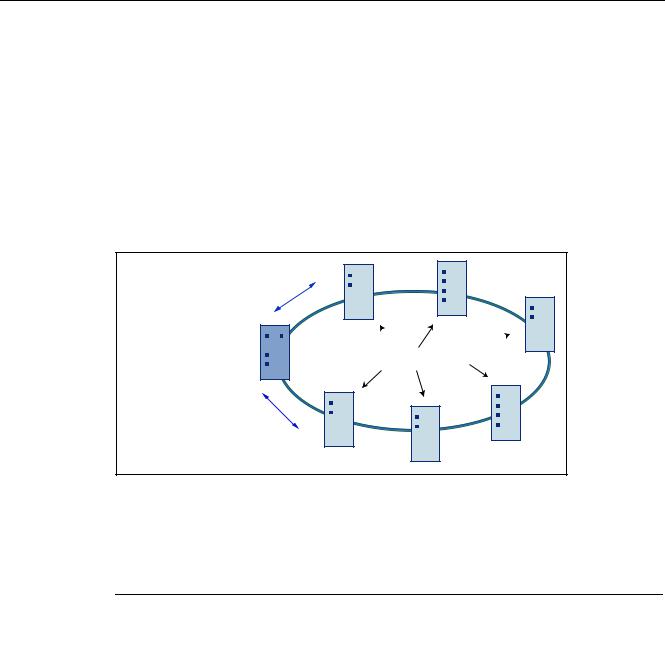
Structure of a ring topology
Nodes in a ring topology can be external switches and/or the integrated switches of communications modules.
To set up a ring topology with media redundancy, you bring together the two free ends of a linear bus topology in one device. Closing the linear bus topology to form a ring is achieved with two ports (ring ports) of a device in the ring. This device is the redundancy manager. All other devices in the ring are redundancy clients.
7HVW IUDPHV
5HGXQGDQF\ PDQDJHU 


 5HGXQGDQF\ FOLHQWV
7HVW IUDPHV
Figure 2-8 Devices in a ring topology with media redundancy
The two ring ports of a device are the ports that establish the connection to its two neighboring devices in the ring topology. The ring ports are selected and set in the configuration of the relevant device. On the S7 Ethernet CP modules, the ring ports are indicated by an "R" after the port number.
Note
Create the configuration of the devices to be connected to form a ring before you close the ring.
How media redundancy works in a ring topology
When using media redundancy, the data paths between the individual devices are reconfigured if the ring is interrupted at one point. Following reconfiguration of the topology, the devices can once again be reached in the resulting new topology.
In the redundancy manager, the 2 ring ports are disconnected from each other if the network is uninterrupted. This prevents circulating data frames. In terms of data transmission, the ring topology is a linear bus topology. The redundancy manager monitors the ring topology. It does this by sending test frames both from ring port 1 and ring port 2. The test frames run round the ring in both directions until they arrive at the other ring port of the redundancy manager.
SCALANCE X-200 |
|
Operating Instructions, 12/2011, A5E00349864-19 |
23 |

Network topologies /media redundancy
2.3 Media redundancy in ring topologies
An interruption of the ring can be caused by loss of the connection between two devices or by failure of a device in the ring.
If the test frames of the redundancy manager no longer arrive at the other ring port, the redundancy manager connects its two ring ports. This substitute path once again restores a functioning connection between all remaining devices in the form of a linear bus topology.
The time between the ring interruption and restoration of a functional linear topology is known as the reconfiguration time.
As soon as the interruption is eliminated, the original transmission paths are established again, the two ring ports of the redundancy manager are disconnected and the redundancy clients informed of the change. The redundancy clients then use the new paths to the other devices.
If the redundancy manager fails, the ring becomes a functional linear bus.
Media redundancy methods
The following media redundancy methods are supported by SIMATIC NET products for ring topologies:
●HSR (High Speed Redundancy) Reconfiguration time: 0.3 seconds
●MRP (Media Redundancy Protocol)
Reconfiguration time: 0.2 seconds Automatic configuration of the ring
The mechanisms of these methods are similar. With both methods, up to 50 devices can participate in the ring. HSR and MRP cannot be used in the ring at the same time.
If you configure your plant using STEP 7, you can only select MRP as the media redundancy method.
If you configure your devices with Web Based Management, CLI or SNMP, you can choose either HSR or MRP.
Media redundancy with IRT
For ring topologies in which MRP is activated, the "MRPD" function is activated automatically for IRT devices capable of IRT, if this is supported by the device.
●MRPD (Media Redundancy with Path Duplication) For use only with SCALANCE X-200IRT
This procedure allows redundancy with IRT. You will find details in the section MRPD (Page 27).
|
SCALANCE X-200 |
24 |
Operating Instructions, 12/2011, A5E00349864-19 |

Network topologies /media redundancy
2.4 MRP
2.4MRP
The "MRP" method conforms to the Media Redundancy Protocol (MRP) specified in the standard IEC 62439-2 Edition 1.0 2010-02.
The reconfiguration time after an interruption of the ring is a maximum of 0.2 seconds.
Requirements
The following requirements must be met for problem-free operation with the MRP media redundancy protocol:
●MRP is supported in ring topologies with up to 50 devices. Exceeding this number of devices can lead to a loss of data traffic.
●The ring in which you want to use MRP may only consist of devices that support this function. This applies, for example, to the following devices:
–Industrial Ethernet switches
SCALANCE X-200 as of firmware version V4.0 SCALANCE X-200 IRT as of firmware version V4.0 SCALANCE X-300 as of firmware version V3.0 SCALANCE X-400 as of firmware version V3.0
–Communications processors
CP 443-1 Advanced (6GK7 443-1GX20-0XE0) as of firmware version V2.0 CP 343-1 Advanced (6GK7 343-1GX30-0XE0) as of firmware version V1.0 CP 1616 (6GK1 161-6AA00) as of firmware version V2.2
CP 1604 (6GK1 160-4AA00) as of firmware version V2.2
–Non-Siemens devices that support this functionality.
Further Siemens devices are planned that will support MRP.
●All devices must be interconnected via their ring ports.
●If you configure in STEP 7, MRP must be enabled on all devices in the ring (see "MRP configuration in PROFINET IO").
●If you configure with Web Based Management, CLI or SNMP, set all the devices in the ring to "MRP Client" or "Automatic Redundancy Detection". At least one device in the ring must have the setting "Automatic Redundancy Detection".
In their basic status, the "Automatic Redundancy Detection" mode is set on IE switches as default.
●The connection settings (transmission medium / duplex) must be set to full duplex and at least 100 Mbps for all ring ports. Otherwise there may be a loss of data traffic.
–To do this, set all the ports involved in the ring to "Automatic settings" in the "Options" tab of the properties dialog during STEP 7 configuration.
–If you configure with Web Based Management, the ring ports are set automatically to autonegotiation.
SCALANCE X-200 |
|
Operating Instructions, 12/2011, A5E00349864-19 |
25 |
Network topologies /media redundancy
2.4 MRP
Topology
The following schematic shows a possible topology for devices in a ring with MRP.
6 |
7 |
|
|
|
8 |
1 |
|
|
2 |
|
3 |
5HGXQGDQF\ GRPDLQ |
|
|
9 |
5 |
|
4 |
|
|
10 |
6 ZLWK &3$GYDQFHG +0, VWDWLRQ
6&$/$1&( ; VZLWFK (QJLQHHULQJ VWDWLRQ
3& ZLWK &3 |
(7 6 |
6 ZLWK &3$GYDQFHG (7 0
(7 SUR
Figure 2-9 Example of a ring topology with the MRP media redundancy protocol
The following rules apply to a ring topology with media redundancy using MRP:
●All the devices connected within the ring topology are members of the same redundancy domain.
●One device in the ring is acting as redundancy manager.
●All other devices in the ring are redundancy clients.
Non MRP-compliant devices can be connected to the ring via a SCALANCE X switch or via a PC with a CP 1616.
Note
SCALANCE X-300 - modular devices (M)
Remember that in the modular switches the ring ports are located on MM900 media modules.
SCALANCE X-200
26 |
Operating Instructions, 12/2011, A5E00349864-19 |

Network topologies /media redundancy
2.5 MRPD
2.5MRPD
The redundancy procedure MRPD (Media Redundancy with Path Duplication)
The MRPD procedure is specified in IEC 61158 Parts 5 and 6 type 10 "PROFINET". It allows redundancy for PROFINET IRT.
In MRPD, the cyclic IRT frames are duplicated and sent to the recipient via different paths. The two redundant paths are planned in STEP 7. Two different paths are then available if the entire network or part of it has a ring topology.
Requirements
●All devices involved must support IRT.
●All devices involved must support MRPD.
Among the Industrial Ethernet switches, this means the following devices:
– SCALANCE X-200IRT as of firmware version 5.0
●STEP 7 as of version V5.5 SP1
Project engineering
MRPD can only configured in STEP 7 and there are no alternative configuration options.
To prevent loops forming and to ensure redundancy for other types of communication, MRP is always required for MRPD. If you activate MRP in STEP 7, products capable of IRT and MRPD use MRPD automatically.
The "High Performance" version of IRT must be used and the topology of the network must be configured.
SCALANCE X-200 |
|
Operating Instructions, 12/2011, A5E00349864-19 |
27 |

Network topologies /media redundancy
2.6 HSR
2.6HSR
The "HSR" method allows a reconfiguration time of 0.3 seconds following an interruption in the ring.
Requirements
The following requirements must be met for problem-free operation with the HSR media redundancy method:
●HSR is supported in ring topologies with up to 50 devices. Exceeding this number of devices can lead to a loss of data traffic.
●The ring in which you want to use HSR may only consist of devices that support this function. This applies, for example, to the following devices: X-400 IE switches, X-300 IE switches, X-200 IE switches and OSM / ESM.
●All devices must be interconnected via their ring ports.
●A device in the ring must be configured as redundancy manager by selecting the "HSR Manager" setting. You can do this with the button on the front of the device, Web Based Management, CLI or SNMP.
●On all other devices in the ring, either the "HSR Client" or "Automatic Redundancy Detection" mode must be activated.
You can do this with Web Based Management, CLI or SNMP.
●In the basic status, the "HSR Client" or "Automatic Redundancy Detection" mode is set as default.
|
SCALANCE X-200 |
28 |
Operating Instructions, 12/2011, A5E00349864-19 |
Network topologies /media redundancy
2.7 Redundant coupling of network segments
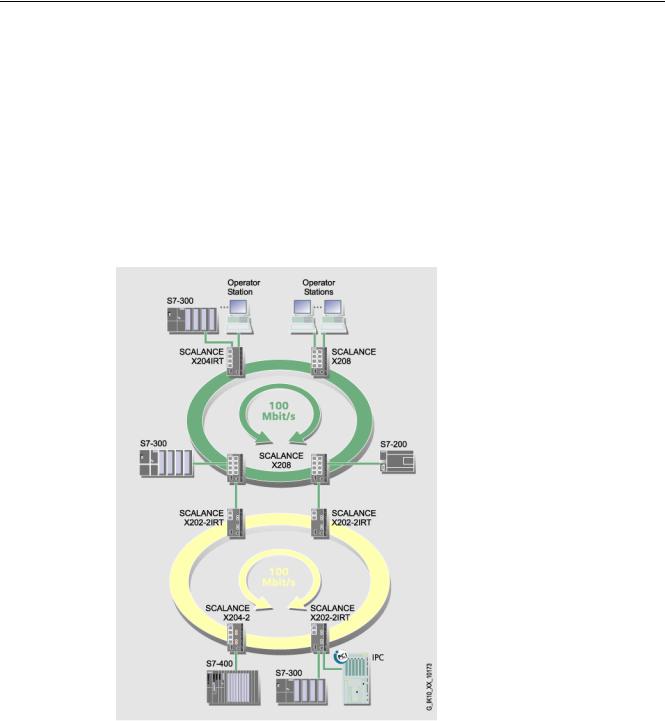
2.7Redundant coupling of network segments
Coupling option
The coupling of two network segments shown here as an example is possible with X- 200IRT, X-300 and X-400 IE switches. This requires the standby function of these devices that can be set via the WEB interface or CLI.
If the standby function is enabled, this is signaled on X-200 IE switches by the RM-LED. The SCALANCE X-200IRT can be operated either as an RM or in standby mode.
Figure 2-10 Redundant coupling of SCALANCE X-200 rings with 2 SCALANCE X-200 IRT devices
SCALANCE X-200 |
|
Operating Instructions, 12/2011, A5E00349864-19 |
29 |

Network topologies /media redundancy
2.7 Redundant coupling of network segments
|
SCALANCE X-200 |
30 |
Operating Instructions, 12/2011, A5E00349864-19 |
Loading...