


 Loading...
FUJI-Reader
SP
Service Manual
Checks, Replacement and Adjustment of Parts
|
|
|
|
|
© Siemens AG 2003 |
|
|
|
The reproduction, transmission or |
|
|
|
use of this document or its contents |
|
|
|
is not permitted without express |
|
|
|
written authority. Offenders will be |
|
|
|
liable for damages. All |
rights, |
|
|
including rights created by patent |
|
|
|
grant or registration of a utility |
|
|
|
model _or_ design,_are_ reserved. |
|
|
|
English |
|
|
Print No.: SPB7-420.840.53.01.02 |
Doc. Gen. Date: |
01.03 |
|
Replaces: n.a.

CR-IR347/CR-IR347P
Service Manual
Checks, Replacement and Adjustment
of Parts (MC)

Contents Maintenance Checks, Replacement and Adjustment of Parts |
0.1 |
CR-IR347 Service Manual – Contents
Checks, Replacement and Adjustment of Parts (MC)
1. Check/Adjustment Procedures for Each Unit............................................................ |
MC-2 |
|
2. Table of Contents ......................................................................................................... |
MC-4 |
|
3. Removing and Installing the Covers .......................................................................... |
MC-8 |
|
4. Removing and Installing the Cassette Set Unit ......................................................... |
MC-10 |
|
4.1 |
Cassette Set Unit ............................................................................................... |
MC-10 |
4.2 |
Shutter ................................................................................................................ |
MC-12 |
4.3 |
Cassette Ejection Sensor (SK1) ....................................................................... |
MC-14 |
4.4 |
Barcode Reader (BCRK1).................................................................................. |
MC-16 |
4.5 |
Pulling Out the Tray ........................................................................................... |
MC-20 |
4.6 |
Cassette Hold Solenoid (SOLK1) ..................................................................... |
MC-26 |
4.7 |
Cassette Hold Sensor (SK3) ............................................................................. |
MC-32 |
4.8 |
Claw Guide Assembly ....................................................................................... |
MC-34 |
4.9 |
Cassette IN Sensor (SK2) .................................................................................. |
MC-40 |
4.10 |
Rubber Roller ..................................................................................................... |
MC-50 |
4.11 |
Guide Plate ......................................................................................................... |
MC-52 |
4.12 |
Guide Stoppers .................................................................................................. |
MC-64 |
4.13 |
Movable Guides ................................................................................................. |
MC-66 |
5. Removing and Installing the IP Removal Unit ........................................................... |
MC-74 |
|
5.1 |
IP Removal Unit.................................................................................................. |
MC-74 |
5.2 |
IP Leak Valve (SVL1).......................................................................................... |
MC-78 |
5.3 |
Suction Cup HP Sensor (SL1)........................................................................... |
MC-80 |
5.4 |
Timing Belt (for IP Conveyance)....................................................................... |
MC-86 |
5.5 |
Guide Plate A...................................................................................................... |
MC-90 |
5.6 |
Rubber Rollers C and D..................................................................................... |
MC-92 |
5.7 |
Rubber Roller (Large) ........................................................................................ |
MC-94 |
5.8 |
Guide Plate D...................................................................................................... |
MC-96 |
5.9 |
Guide Plates B and C......................................................................................... |
MC-98 |
5.10 |
Supports (for IP Removal Arm) ........................................................................ |
MC-100 |
5.11 |
Suction Cups ...................................................................................................... |
MC-104 |
5.12 |
IP Suction Pump (PL1) ...................................................................................... |
MC-108 |
5.13 |
Inch/Metric Sensor (SL4) ................................................................................... |
MC-110 |
5.14 |
Suction Sensor (SL5)......................................................................................... |
MC-112 |
5.15 |
Receiver Rollers ................................................................................................. |
MC-114 |
5.16 |
Guide Plates E, F, and G ................................................................................... |
MC-118 |
5.17 |
Suction Cup Driving Motor (ML1) ..................................................................... |
MC-120 |
009-058-03 08.30.2002 FM3476
CR-IR347 Service Manual |
0.1 |
|
|
|
|

Contents Maintenance Checks, Replacement and Adjustment of Parts |
0.2 |
5.18 |
Timing Belt (for Suction Cup Drive) ................................................................. |
MC-122 |
5.19 |
Shaft (for Suction Cup Drive)............................................................................ |
MC-124 |
5.20 |
IP Removal Unit Upper Assembly .................................................................... |
MC-128 |
5.21 |
Rubber Roller A.................................................................................................. |
MC-130 |
5.22 |
IP Transport Motor (ML2) .................................................................................. |
MC-132 |
5.23 |
Shaft (for IP Conveyance) ................................................................................. |
MC-134 |
5.24 |
Rubber Roller B.................................................................................................. |
MC-136 |
6. Removing and Installing the Erasure Conveyor ....................................................... |
MC-138 |
|
6.1 |
Erasure Lamp Assembly ................................................................................... |
MC-138 |
6.2 |
Erasure Conveyor .............................................................................................. |
MC-140 |
6.3 |
Cleaning Roller Assembly................................................................................. |
MC-144 |
6.4 |
Cleaning Rollers................................................................................................. |
MC-146 |
6.5 |
Erasure Lamps (LAMP1-LAMP5) ...................................................................... |
MC-148 |
6.6 |
Erasure Thermostatic Switch (TSW2) .............................................................. |
MC-150 |
6.7 |
Erasure Thermostatic Switch (TSW1) .............................................................. |
MC-152 |
6.8 |
Erasure Cooling Fan (FANM1) .......................................................................... |
MC-154 |
6.9 |
Sockets ............................................................................................................... |
MC-156 |
6.10 |
Timing Belts ....................................................................................................... |
MC-160 |
6.11 |
Lamp House Assembly ..................................................................................... |
MC-164 |
6.12 |
Filter .................................................................................................................... |
MC-166 |
6.13 |
Reflection Plate .................................................................................................. |
MC-168 |
6.14 |
IP Transport Motor (MM1) ................................................................................. |
MC-170 |
6.15 |
Rubber Rollers (Upper) ..................................................................................... |
MC-172 |
6.16 |
Light Protect Plates ........................................................................................... |
MC-174 |
6.17 |
Rubber Rollers (Lower) ..................................................................................... |
MC-176 |
6.18 |
Guide Plates ....................................................................................................... |
MC-178 |
7. Pulling Out and Pushing In the Scanner Unit............................................................ |
MC-182 |
|
009-058-03 08.30.2002 FM3476
CR-IR347 Service Manual |
0.2 |
|
|
|
|

Contents Maintenance Checks, Replacement and Adjustment of Parts |
0.3 |
8. Removing and Installing the Side-Positioning Conveyor ......................................... |
MC-188 |
|
8.1 |
Side-Positioning Conveyor ............................................................................... |
MC-188 |
8.2 |
Grip Release Motor (MN2) ................................................................................. |
MC-192 |
8.3 |
Barcode Reader (BCRN1).................................................................................. |
MC-194 |
8.4 |
Side-Positioning Mechanism HP Sensor (SN1) .............................................. |
MC-196 |
8.5 |
Grip Release HP Sensor (SN2) ......................................................................... |
MC-198 |
8.6 |
Cleaning Guide Drive Motor (MN4)................................................................... |
MC-200 |
8.7 |
BCR08A Board ................................................................................................... |
MC-202 |
8.8 |
Side-Positioning IP Sensor (SN3)..................................................................... |
MC-204 |
8.9 |
Cleaning Guide HP Sensor (SN4) ..................................................................... |
MC-206 |
8.10 |
Cleaning Guide Assembly................................................................................. |
MC-208 |
8.11 |
Shaft (for Cleaning Guide Assembly) .............................................................. |
MC-214 |
8.12 |
Guide Plate C...................................................................................................... |
MC-218 |
8.13 |
Timing Belt (for IP Conveyance)....................................................................... |
MC-220 |
8.14 |
Guide Plate G ..................................................................................................... |
MC-222 |
8.15 |
Rubber Rollers (Rear) ........................................................................................ |
MC-226 |
8.16 |
Wires (Left Side)................................................................................................. |
MC-230 |
8.17 |
Wires (Right Side) .............................................................................................. |
MC-234 |
8.18 |
Timing Belt (for Side-Positioning Mechanism) ............................................... |
MC-240 |
8.19 |
Shaft (for Grip Release) ..................................................................................... |
MC-246 |
9. Removing and Installing the Scanning Optics Unit .................................................. |
MC-250 |
|
9.1 |
Adjusting the Format ......................................................................................... |
MC-250 |
9.2 |
Shading and Sensitivity Corrections ............................................................... |
MC-254 |
9.3 |
Checking for Image Problems .......................................................................... |
MC-258 |
9.4 |
Removing and Installing the Scanning Optics Unit........................................ |
MC-262 |
9.5 |
LD Assembly ...................................................................................................... |
MC-266 |
9.6 |
Polygon Assembly ............................................................................................. |
MC-270 |
9.7 |
SYN08A Board.................................................................................................... |
MC-274 |
009-058-03 08.30.2002 FM3476
CR-IR347 Service Manual |
0.3 |
|
|
|
|

Contents Maintenance Checks, Replacement and Adjustment of Parts |
0.4 |
10. Removing and Installing the Subscanning Unit........................................................ |
MC-278 |
|
10.1 |
Driving-Side Grip Release HP Sensor (SZ2).................................................... |
MC-278 |
10.2 |
Mirror HP Sensor (SZ4) ..................................................................................... |
MC-280 |
10.3 |
Rubber Belt and SUS Belt ................................................................................. |
MC-282 |
10.4 |
Kapton® Belt ...................................................................................................... |
MC-284 |
10.5 |
Flywheel .............................................................................................................. |
MC-286 |
10.6 |
Subscanning Motor MZ1 (FFM) ........................................................................ |
MC-288 |
10.7 |
PMT08D Board ................................................................................................... |
MC-292 |
10.8 |
PMR08C Board ................................................................................................... |
MC-296 |
10.9 |
Light-Collecting Guide Assembly (for Front Surface) .................................... |
MC-300 |
10.10 |
Light-Collecting Guide Assembly (for Back Surface) .................................... |
MC-308 |
10.11 |
Light-Collecting Mirror and IP Leading-Edge Sensor (SZ1/SED08D) ........... |
MC-320 |
10.12 |
Glass Guide ........................................................................................................ |
MC-326 |
10.13 |
Lower Rubber Rollers........................................................................................ |
MC-332 |
10.14 |
Mirror Driving Motor (MZ4)................................................................................ |
MC-336 |
10.15 |
Driving-Shaft Grip Motor (MZ2) ........................................................................ |
MC-338 |
10.16 |
Driven-Shaft Grip Motor (MZ3).......................................................................... |
MC-342 |
10.17 |
Driven-Side Grip Release HP Sensor (SZ3) ..................................................... |
MC-346 |
10.18 |
Subscanning Unit Controller Assembly .......................................................... |
MC-348 |
10.19 |
SCN08D/SCR08D Board .................................................................................... |
MC-354 |
10.20 |
PHV08D Board.................................................................................................... |
MC-358 |
11. Removing and Installing the Hard Disk Drive (HDD) ................................................ |
MC-360 |
|
11.1 |
Setting HDD ........................................................................................................ |
MC-361 |
11.2 |
Hard Disk Drive (HDD) ....................................................................................... |
MC-362 |
12. Removing and Installing the Floppy Disk Drive (FDD) ............................................. |
MC-372 |
|
12.1 |
Setting FDD ........................................................................................................ |
MC-372 |
12.2 |
Floppy Disk Drive (FDD) .................................................................................... |
MC-372 |
009-058-03 08.30.2002 FM3476
CR-IR347 Service Manual |
0.4 |
|
|
|
|

Contents Maintenance Checks, Replacement and Adjustment of Parts |
0.5 |
13. Removing and Installing the Power Supply Unit (JPS-6) ......................................... |
MC-374 |
|
13.1 |
Power Supply Unit (JPS-6) ................................................................................ |
MC-374 |
13.2 |
Power Supply Unit Fuses .................................................................................. |
MC-378 |
14. Removing and Installing the Monitor ......................................................................... |
MC-382 |
|
14.1 |
CRT (Monitor) ..................................................................................................... |
MC-382 |
14.2 |
Fuse Between Power Supply Unit and CRT .................................................... |
MC-388 |
15. Removing and Installing the PC Boards .................................................................... |
MC-390 |
|
15.1 |
MTH08C Board ................................................................................................... |
MC-402 |
15.2 |
MTH08D Board ................................................................................................... |
MC-404 |
15.3 |
CPU90E Board.................................................................................................... |
MC-406 |
15.4 |
IMG07B Board .................................................................................................... |
MC-410 |
15.5 |
BSP08A Board.................................................................................................... |
MC-411 |
15.6 |
IMG08M Board .................................................................................................... |
MC-413 |
15.7 |
CPU90F Board (Optional) .................................................................................. |
MC-414 |
15.8 |
LAN90B Board (Optional).................................................................................. |
MC-416 |
15.9 |
HCP08A Board (Optional) ................................................................................. |
MC-417 |
15.10 |
IMG08H Board (Optional) .................................................................................. |
MC-418 |
15.11 |
SNS08C and DRV08A Boards ........................................................................... |
MC-420 |
15.12 |
VOL08A Board.................................................................................................... |
MC-427 |
15.13 |
LED08A Board .................................................................................................... |
MC-428 |
15.14 |
LED08B Board .................................................................................................... |
MC-428 |
15.15 |
BCR08A Board ................................................................................................... |
MC-429 |
15.16 |
SYN08A, PMT08D, PMR08C, SCN08D/SCR08D, and PHV08D boards .......... |
MC-429 |
009-058-03 08.30.2002 FM3476
CR-IR347 Service Manual |
0.5 |
|
|
|
|

Checks, Replacement and Adjustment of Parts (MC) Control Sheet |
MC - 1 |
|||||
|
|
|
Control Sheet |
|
|
|
|
|
|
|
|
||
|
|
|
Issue date |
Revision number |
Reason |
Pages affected |
10/20/2000 |
00 |
New release (FM2732) |
All pages |
|||
05/15/2001 |
01 |
Corrections (FM3052) |
MC - 9, 93, 146, 265, 331 |
|||
08/30/2001 |
02 |
Design changes; measures against noise |
MC - 25, 91, 93, 95, 130, 131, |
|||
|
|
|
|
|
(FM3142) |
137, 142-145, 161-162, 173, 177, |
|
|
|
|
|
|
178, 180, 183, 184, 208-210, 214, |
|
|
|
|
|
|
215, 223-225, 227-229, 241, 244, |
|
|
|
|
|
|
245, 263, 267, 271, 275, 327, |
|
|
|
|
|
|
328, 331, 333, 334, 349-353, |
|
|
|
|
|
|
353.1-353.8, 361, 361.1-361.4, |
|
|
|
|
|
|
362, 401 |
08/30/2002 |
03 |
Scanning optics unit, HDD, and other |
MC - 6, 7, 33, 37, 148, 254–261, |
|||
|
|
|
|
|
information added (FM3476) |
261.1–261.4, 262–265, |
|
|
|
|
|
|
265.1–265.8, 275, 293, 297, |
|
|
|
|
|
|
356, 357, 359–429 |
009-058-03 08.30.2002 FM3476
CR-IR347 Service Manual |
MC - 1 |
|
|
|
|
MC - 2
1.Check/Adjustment Procedures for Each Unit
Precautions for Check, Replacement, and Adjustment
In this volume, descriptions are omitted regarding components that do not require special attention or adjustment during their removal/reinstallation. For removal procedures for such components, refer to the Parts List Volume.
When performing check/replacement/adjustment procedures on the machine, the following precautions should be observed.
 WARNING
To avoid electric shock hazards, power OFF the machine before performing the procedures.
 WARNING/CAUTION
Observe the warnings and cautions described in the “Safety Precautions.”
 CAUTION
Never remove screws to which red paint is applied.
INSTRUCTION
Screws to which yellow paint is applied need to be adjusted at the time of component installation. When installing a component, follow the specified check/adjustment procedure.
Some of the illustrations in this volume contain check/adjustment and half-punch indicators as needed.
For removal and reinstallation, perform the procedures as instructed by such indicators.
• Check/Adjustment indicator:
CHECK
• Half-punch indicator:
Indicates that it is necessary to check or adjust the installation location when the part or component removed is to be reinstalled.
This indicator is placed in the illustration that depicts the procedures for removing the parts and components.
When you see this indicator, refer to its relevant “■ Check/ Adjustment Procedures.”
Indicates that it is necessary to align the half-punches when installing the parts or components.
However, it is not indicated for the half-punches for improving ease of assembly or preventing erroneous assembly procedures.
009-058-00 10.20.2000 FM2732 (2)
CR-IR347 Service Manual |
MC - 2 |
|
|
|
|

MC - 3
BLANK PAGE
009-058-00 10.20.2000 FM2732 (2)
CR-IR347 Service Manual |
MC - 3 |
|
|
|
|
MC - 4
2.Table of Contents
3. Covers |
3. Removing and Installing the Covers |
MC-8 |
4. Cassette set unit |
4. Removing and Installing the Cassette Set Unit |
MC-10 |
|
|
4.1 |
Cassette Set Unit |
MC-10 |
|
4.2 |
Shutter |
MC-12 |
|
4.3 |
Cassette Ejection Sensor (SK1) |
MC-14 |
|
4.4 |
Barcode Reader (BCRK1) |
MC-16 |
|
4.5 |
Pulling Out the Tray |
MC-20 |
|
4.6 |
Cassette Hold Solenoid (SOLK1) |
MC-26 |
|
4.7 |
Cassette Hold Sensor (SK3) |
MC-32 |
|
4.8 |
Claw Guide Assembly |
MC-34 |
|
4.9 |
Cassette IN Sensor (SK2) |
MC-40 |
|
4.10 |
Rubber Roller |
MC-50 |
|
4.11 |
Guide Plate |
MC-52 |
|
4.12 |
Guide Stoppers |
MC-64 |
|
4.13 |
Movable Guides |
MC-66 |
5. IP Removal Unit |
5. Removing and Installing the IP Removal Unit |
MC-74 |
|
|
5.1 |
IP Removal Unit |
MC-74 |
|
5.2 |
IP leak valve (SVL1) |
MC-78 |
|
5.3 |
Suction Cup HP Sensor (SL1) |
MC-80 |
|
5.4 |
Timing Belt (for IP Conveyance) |
MC-86 |
|
5.5 |
Guide Plate A |
MC-90 |
|
5.6 |
Rubber Rollers C and D |
MC-92 |
|
5.7 |
Rubber Roller (Large) |
MC-94 |
|
5.8 |
Guide Plate D |
MC-96 |
|
5.9 |
Guides Plates B and C |
MC-98 |
|
5.10 |
Supports (for IP Removal Arm) |
MC-100 |
|
5.11 |
Suction Cups |
MC-104 |
|
5.12 |
IP Suction Pump (PL1) |
MC-108 |
|
5.13 |
Inch/Metric Sensor (SL4) |
MC-110 |
|
5.14 |
Suction Sensor (SL5) |
MC-112 |
|
5.15 |
Receiver rollers |
MC-114 |
|
5.16 |
Guide Plates E, F, and G |
MC-118 |
|
5.17 |
Suction Cup Driving Motor (ML1) |
MC-120 |
|
5.18 |
Timing Belt (for Suction Cup Drive) |
MC-122 |
|
5.19 |
Shaft (for Suction Cup Drive) |
MC-124 |
|
5.20 |
IP Removal Unit Upper Assembly |
MC-128 |
|
5.21 |
Rubber Roller A |
MC-130 |
|
5.22 |
IP Transport Motor (ML2) |
MC-132 |
|
5.23 |
Shaft (for IP Conveyance) |
MC-134 |
|
5.24 |
Rubber Roller B |
MC-136 |
FR7H30AC.EPS
009-058-00 10.20.2000 FM2732 (2)
CR-IR347 Service Manual |
MC - 4 |
|
|
|
|
MC - 5
6. Erasure conveyor |
6. Removing and Installing the Erasure Conveyor |
MC-138 |
|
|
6.1 |
Erasure Lamp Assembly |
MC-138 |
|
6.2 |
Erasure Conveyor |
MC-140 |
|
6.3 |
Cleaning Roller Assembly |
MC-144 |
|
6.4 |
Cleaning Rollers |
MC-146 |
|
6.5 |
Erasure Lamps (LAMP1-LAMP5) |
MC-148 |
|
6.6 |
Erasure Thermostatic Switch (TSW2) |
MC-150 |
|
6.7 |
Erasure Thermostatic Switch (TSW1) |
MC-152 |
|
6.8 |
Erasure Cooling Fan (FANM1) |
MC-154 |
|
6.9 |
Sockets |
MC-156 |
|
6.10 Timing Belts |
MC-160 |
|
|
6.11 Lamp House Assembly |
MC-164 |
|
|
6.12 Filter |
MC-166 |
|
|
6.13 Reflection Plate |
MC-168 |
|
|
6.14 IP Transport Motor (MM1) |
MC-170 |
|
|
6.15 Rubber Rollers (Upper) |
MC-172 |
|
|
6.16 Shielding Plates |
MC-174 |
|
|
6.17 Rubber Rollers (Lower) |
MC-176 |
|
|
6.18 Guide Plates |
MC-178 |
|
7. Scanner unit |
7. Pulling Out and Pushing In the Scanner Unit |
MC-182 |
|
8. Side-positioning conveyor |
8. Removing and Installing the Side-Positioning Conveyor |
MC-188 |
|
|
8.1 |
Side-Positioning Conveyor |
MC-188 |
|
8.2 |
Grip Release Motor (MN2) |
MC-192 |
|
8.3 |
Barcode Reader (BCRN1) |
MC-194 |
|
8.4 |
Side-Positioning Mechanism HP Sensor (SN1) |
MC-196 |
|
8.5 |
Grip Release HP Sensor (SN2) |
MC-198 |
|
8.6 |
Cleaning Guide Drive Motor (MN4) |
MC-200 |
|
8.7 |
BCR08A Board |
MC-202 |
|
8.8 |
Side-Positioning IP Sensor (SN3) |
MC-204 |
|
8.9 |
Cleaning Guide HP Sensor (SN4) |
MC-206 |
|
8.10 Cleaning Guide Assembly |
MC-208 |
|
|
8.11 |
Shaft (for Cleaning Guide Assembly) |
MC-214 |
|
8.12 Guide Plate C |
MC-218 |
|
|
8.13 Timing Belt (for IP Conveyance) |
MC-220 |
|
|
8.14 Guide Plate G |
MC-222 |
|
|
8.15 Rubber Rollers (Rear) |
MC-226 |
|
|
8.16 Wire (Left Side) |
MC-230 |
|
|
8.17 Wires (Right Side) |
MC-234 |
|
|
8.18 Timing Belt (for Side-Positioning Mechanism) |
MC-240 |
|
|
8.19 Shaft (for Grip Release) |
MC-246 |
|
FR7H30AD.EPS
009-058-00 10.20.2000 FM2732 (2)
CR-IR347 Service Manual |
MC - 5 |
|
|
|
|
|
|
|
MC - 6 |
9. Scanning optics unit |
9. Removing and Installing the Scanning Optics Unit |
MC-250 |
|
|
9.1 |
Adjusting the Format |
MC-250 |
|
9.2 |
Shading and Sensitivity Corrections |
MC-254 |
|
9.3 |
Checking for Image Problems |
MC-258 |
|
9.4 |
Removing and Installing the Scanning |
|
|
|
Optics Unit |
MC-262 |
|
9.5 |
LD Assembly |
MC-266 |
|
9.6 |
Polygon Assembly |
MC-270 |
|
9.7 |
SYN08A Board |
MC-274 |
10. Subscanning unit |
10. Removing and Installing the Subscanning Unit |
MC-278 |
|
|
10.1 |
Driving-Side Grip Release HP Sensor (SZ2) |
MC-278 |
|
10.2 |
Mirror HP Sensor (SZ4) |
MC-280 |
|
10.3 |
Rubber Belt and SUS Belt |
MC-282 |
|
10.4 |
Kapton® Belt |
MC-284 |
|
10.5 |
Flywheel |
MC-286 |
|
10.6 |
Subscanning Motor MZ1 (FFM) |
MC-288 |
|
10.7 |
PMT08D Board |
MC-292 |
|
10.8 |
PMR08C Board |
MC-296 |
|
10.9 |
Light-Collecting Guide Assembly |
|
|
|
(for Front Surface) |
MC-300 |
|
10.10 |
Light-Collecting Guide Assembly |
|
|
|
(for Back Surface) |
MC-308 |
|
10.11 |
Light-Collecting Mirror and IP Leading-Edge |
|
|
|
Sensor (SZ1/SED08D) |
MC-320 |
|
10.12 |
Glass Guide |
MC-326 |
|
10.13 |
Lower Rubber Rollers |
MC-332 |
|
10.14 |
Mirror Driving Motor (MZ4) |
MC-336 |
|
10.15 |
Driving-Shaft Grip Motor (MZ2) |
MC-338 |
|
10.16 |
Driven-Shaft Grip Motor (MZ3) |
MC-342 |
|
10.17 |
Driven-Side Grip Release HP Sensor (SZ3) |
MC-346 |
|
10.18 |
Subscanning Unit Controller Assembly |
MC-348 |
|
10.19 |
SCN08D/SCR08D Board |
MC-354 |
|
10.20 |
PHV08D Board |
MC-358 |
11. HDD |
11. Removing and Installing the Hard Disk Drive |
|
|
|
(HDD) |
MC-360 |
|
|
11.1 |
Setting HDD |
MC-361 |
|
11.2 |
Hard Disk Drive (HDD) |
MC-362 |
FR7H30AE.EPS
009-058-03 08.30.2002 FM3476
CR-IR347 Service Manual |
MC - 6 |
|
|
|
|
|
|
|
MC - 7 |
12. FDD |
12. Removing and Installing the Floppy Disk |
|
|
|
Drive (FDD) |
MC-372 |
|
|
12.1 |
Setting FDD |
MC-372 |
|
12.2 |
Floppy Disk Drive (FDD) |
MC-372 |
13. Power Supply Unit |
13. Removing and Installing the Power |
|
|
|
Supply Unit (JPS-6) |
MC-374 |
|
|
13.1 |
Power Supply Unit (JPS-6) |
MC-374 |
|
13.2 |
Power Supply Unit Fuses |
MC-378 |
14. Monitor |
14. Removing and Installing the Monitor |
MC-382 |
|
|
14.1 |
CRT (Monitor) |
MC-382 |
|
14.2 |
Fuse Between Power Supply Unit and CRT |
MC-388 |
15. PC Boards |
15. Removing and Installing the PC Boards |
MC-390 |
|
|
15.1 |
MTH08C |
MC-402 |
|
15.2 |
MTH08D |
MC-404 |
|
15.3 |
CPU90E Board |
MC-406 |
|
15.4 |
IMG07B Board |
MC-410 |
|
15.5 |
BSP08A Board |
MC-411 |
|
15.6 |
IMG08M Board |
MC-413 |
|
15.7 |
CPU90F Board (Optional) |
MC-414 |
|
15.8 |
LAN90B Board (Optional) |
MC-416 |
|
15.9 |
HCP08A Board (Optional) |
MC-417 |
|
15.10 |
IMG08H Board (Optional) |
MC-418 |
|
15.11 |
SNS08C and DRV08A Boards |
MC-420 |
|
15.12 |
VOL08A Board |
MC-427 |
|
15.13 |
LED08A Board |
MC-428 |
|
15.14 |
LED08B Board |
MC-428 |
|
15.15 |
BCR08A Board |
MC-429 |
|
15.16 |
SYN08A, PMT08D, PMR08C, SCN08D/SCR08C, |
|
|
|
and PHV08D Boards |
MC-429 |
FR7H30AF.EPS
009-058-03 08.30.2002 FM3476
CR-IR347 Service Manual |
MC - 7 |
|
|
|
|
MC - 8
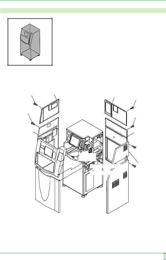
3.Removing and Installing the Covers
FR7H3000.EPS
■ Removal procedure
Upper left-hand side cover
[Remove] |
Upper rear cover |
|
T4x12 (x4) |
||
[Remove] |
||
|
T4x12 (x4) |
|
[Remove] |
|
|
T4x12 (x6) |
[Remove] |
|
T4x6 (x3) |
T4x12 (x8) |
|
Lower left-hand side cover |
Lower rear cover |
|
|
Upper front cover 
Lower front cover 
[Remove] |
BR4x8 (x2) |
[Loosen] T4x12 (x2) |
[Loosen] T4x12 (x2) |
 [Remove]
T4x6 (x4)
Upper right-hand side cover
 [Remove] T4x6 (x7)
 Lower right-hand side cover
FR7H3098.EPS
009-058-00 10.20.2000 FM2732 (2)
CR-IR347 Service Manual |
MC - 8 |
|
|
|
|
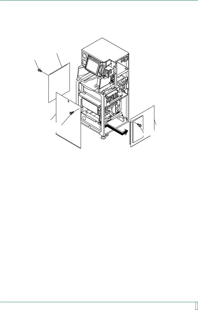
MC - 9
Left-hand inner cover
[Remove] BR4x8 (x6)
Light protect plate |
|
[Remove] |
Right-hand inner cover |
BR4x8 (x9) |
[Remove] BR4x8 (x5) |
|
|
|
FR7H3099.EPS |
■ Installation procedure
Accomplish installation by reversing the removal procedure.
009-058-010 0510.1520.20010 FM3052732 (2)
CR-IR347 Service Manual |
MC - 9 |
|
|
|
|
MC - 10
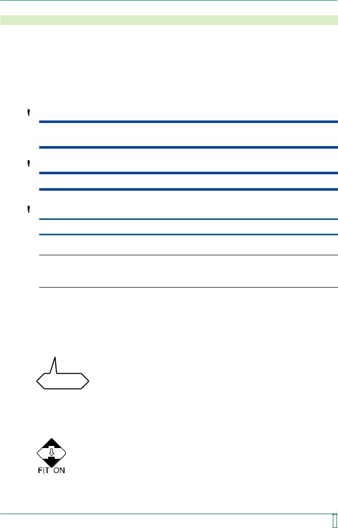
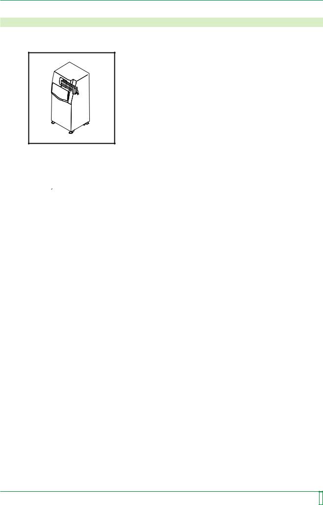
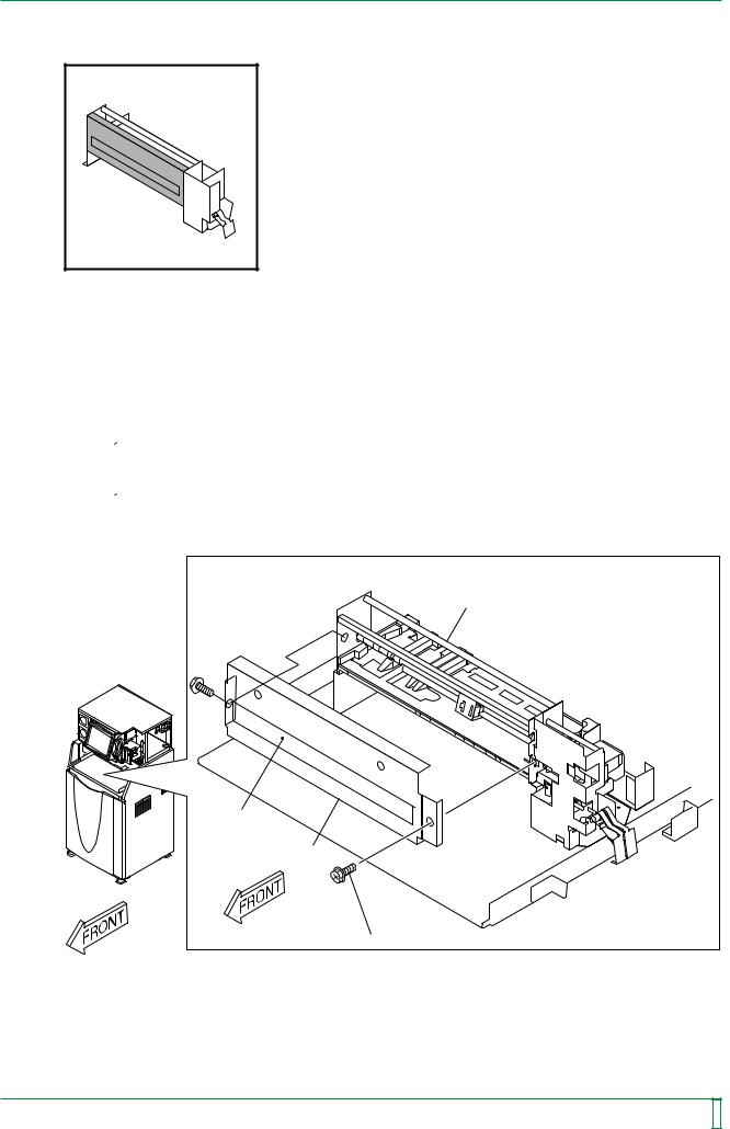
4.Removing and Installing the Cassette Set Unit
4.1Cassette Set Unit
FR7H3001*.EPS
■Removal procedure
(1)Pull out the tray.
 “4.5 Pulling Out the Tray”
009-058-00 10.20.2000 FM2732 (2)
CR-IR347 Service Manual |
MC - 10 |
|
|
|
|
MC - 11
(2)Remove the cassette set unit.
NOTE
Before removing the cassette set unit, place the removal arm in the following position:
#1
[Rotate] Timing belt
IP removal unit 
 IP removal arm
#2
[Remove] BR4x8 (x3)
Cassette set unit 
 Cassette
set unit
Positioning screw
FR7H3315.EPS
Installation procedure
Accomplish installation by reversing the removal procedure.
009-058-00 10.20.2000 FM2732 (2)
CR-IR347 Service Manual |
MC - 11 |
|
|
|
|
MC - 12
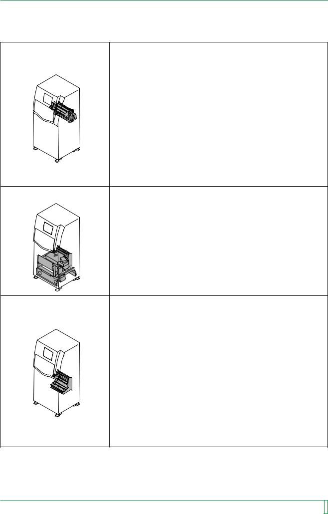
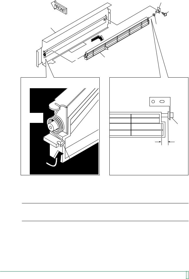
4.2 |
Shutter |
|
FR7H3002.EPS |
■Removal procedure
(1)Remove the following covers:
•Upper right-hand side cover
•Upper left-hand side cover
•Upper front cover
 “3. Removing and Installing the Covers”
(2)Remove the front shelf cover.
 “4.5 Pulling Out the Tray”
(3)Remove the shutter assembly.
Cassette set unit |
Shutter |
Shutter assembly |
[Remove] BR4x8 (x2) |
FR7H3301.EPS |
009-058-00 10.20.2000 FM2732 (2)
CR-IR347 Service Manual |
MC - 12 |
|
|
|
|
MC - 13
(4) Remove the shutter.
Bracket
[Remove]
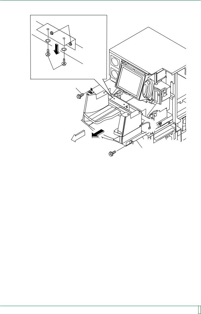
B3x6
Bracket |
Bearing |
|
Shutter
 Bracket
Torsion coil spring
Bearing
Shutter 
A
[Remove] Hook
FR7H3302.EPS
Installation procedure
NOTE
When installing the shutter, ensure that gap A shown above permits the entry of a single thickness of a 150 mm scale but does not permit the entry of a single thickness of a 300 mm scale.
To accomplish installation, reverse the removal procedure.
009-058-00 10.20.2000 FM2732 (2)
CR-IR347 Service Manual |
MC - 13 |
|
|
|
|
MC - 14
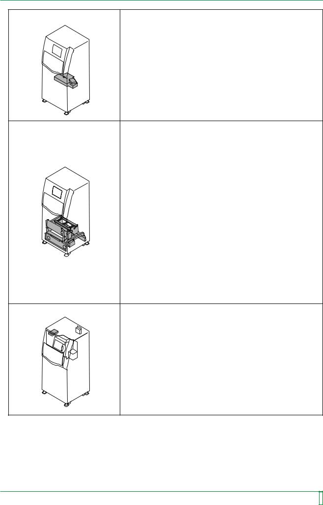
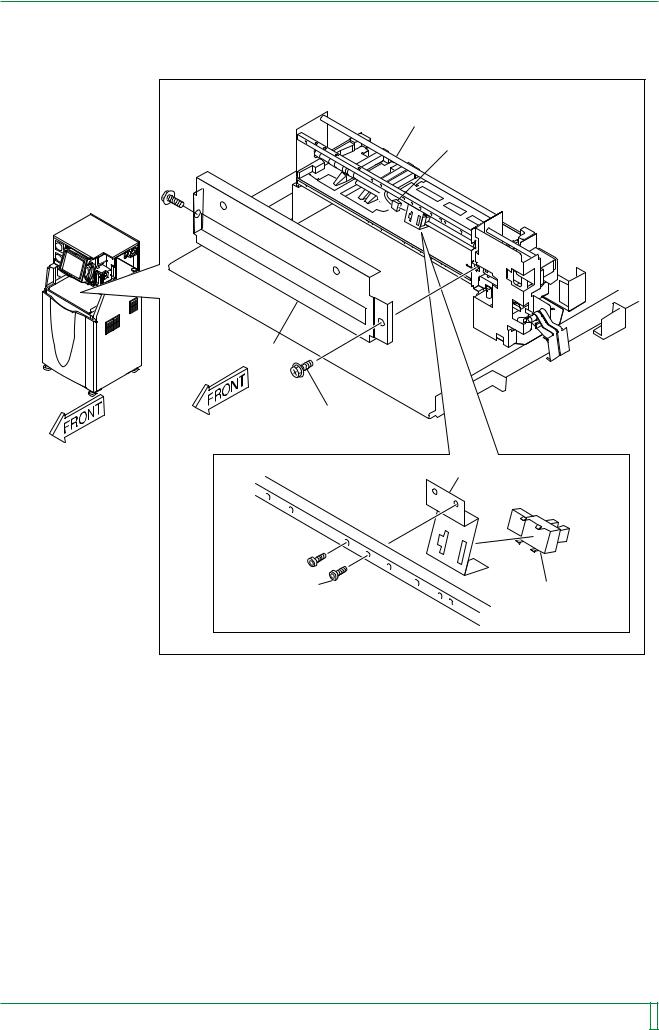
4.3Cassette Ejection Sensor (SK1)
FR7H3003.EPS |
■Removal procedure
(1)Remove the following covers:
•Upper right-hand side cover
•Upper left-hand side cover
•Upper front cover
 “3. Removing and Installing the Covers”
(2)Remove the front shelf cover.
 “4.5 Pulling Out the Tray”
009-058-00 10.20.2000 FM2732 (2)
CR-IR347 Service Manual |
MC - 14 |
|
|
|
|
MC - 15
(3)Remove the shutter assembly.
(4)Remove the cassette ejection sensor (SK1).
|
Cassette set unit |
|
(4) #1 |
|
[Disconnect] Connector (SK1) |
Shutter assembly |
|
|
(3) |
|
[Remove] BR4x8 (x2) |
|
Bracket |
(4) #2 |
(4) #3 |
[Remove] |
|
Q4x12 (x2) |
[Remove] SK1 |
(Loktite) |
|
|
FR7H3304.EPS |
■ Installation procedure
To accomplish installation, reverse the removal procedure.
009-058-00 10.20.2000 FM2732 (2)
CR-IR347 Service Manual |
MC - 15 |
|
|
|
|
MC - 16
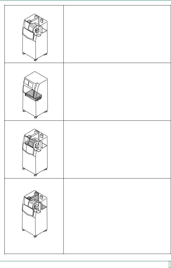
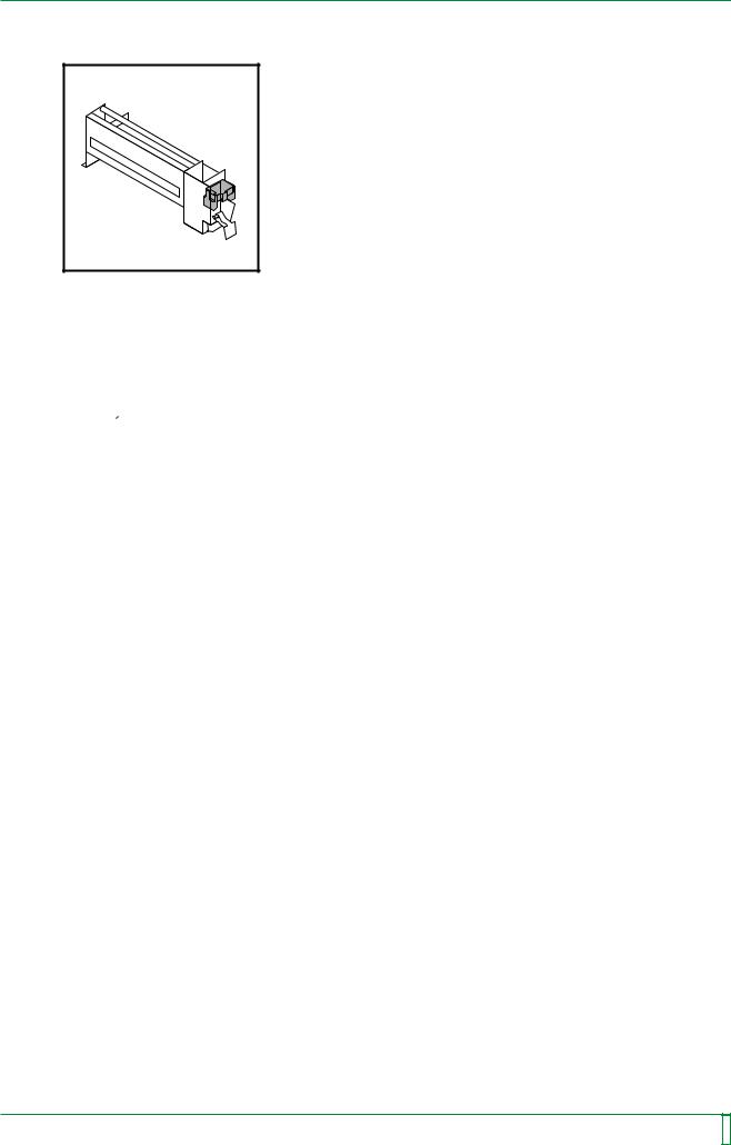
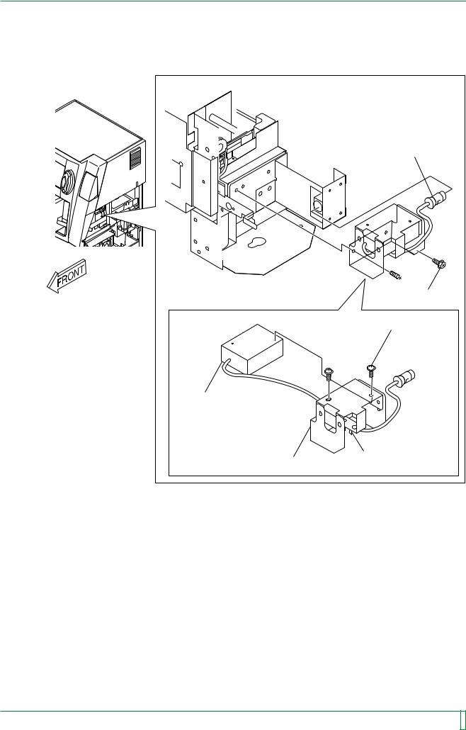
4.4Barcode Reader (BCRK1)
FR7H3004.EPS |
■Removal procedure
(1)Remove the following covers:
•Lower front cover
•Lower right-hand side cover
 “3. Removing and Installing the Covers”
009-058-00 10.20.2000 FM2732 (2)
CR-IR347 Service Manual |
MC - 16 |
|
|
|
|
MC - 17
(2) Remove the barcode reader (BCRK1).
 Cassette set unit
#1 [Disconnect] Connector
 #2 [Remove] BR4x8 (x2)
#4
[Remove] N2x6 (x2)
BCRK1
Bracket |
#3 |
|
[Cut] Tie (x2) |
||
|
FR7H3306.EPS
009-058-00 10.20.2000 FM2732 (2)
CR-IR347 Service Manual |
MC - 17 |
|
|
|
|
MC - 18
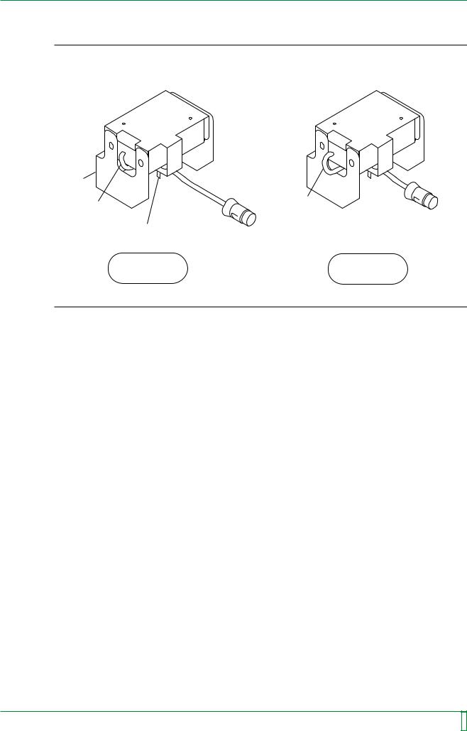
Installation procedure
NOTE
When clamping the cable with a tie, ensure that the cable does not come out of the bracket.
Bracket
Cable
Cable
Tie
OK NG
FR7H3307.EPS
To accomplish installation, reverse the removal procedure.
009-058-00 10.20.2000 FM2732 (2)
CR-IR347 Service Manual |
MC - 18 |
|
|
|
|

MC - 19
BLANK PAGE
009-058-00 10.20.2000 FM2732 (2)
CR-IR347 Service Manual |
MC - 19 |
|
|
|
|
MC - 20
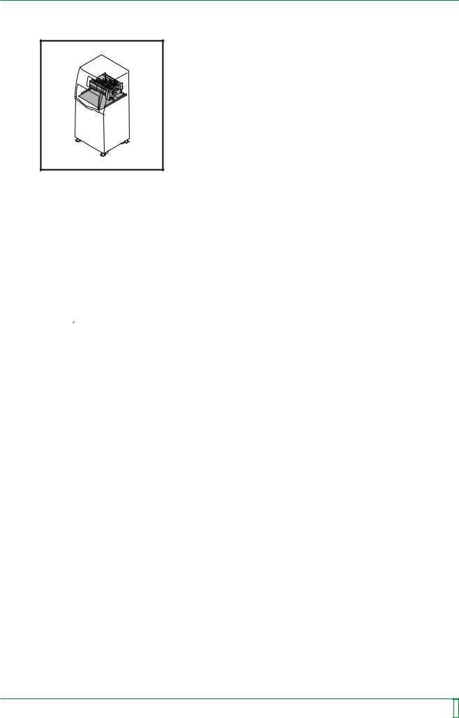
4.5Pulling Out the Tray
FR7H3005.EPS
■Pull-out procedure
(1)Remove the following covers:
•Upper left-hand side cover
•Upper right-hand side cover
•Upper front cover
•Lower front cover
•Lower right-hand side cover
 “3. Removing and Installing the Covers”
009-058-00 10.20.2000 FM2732 (2)
CR-IR347 Service Manual |
MC - 20 |
|
|
|
|
MC - 21
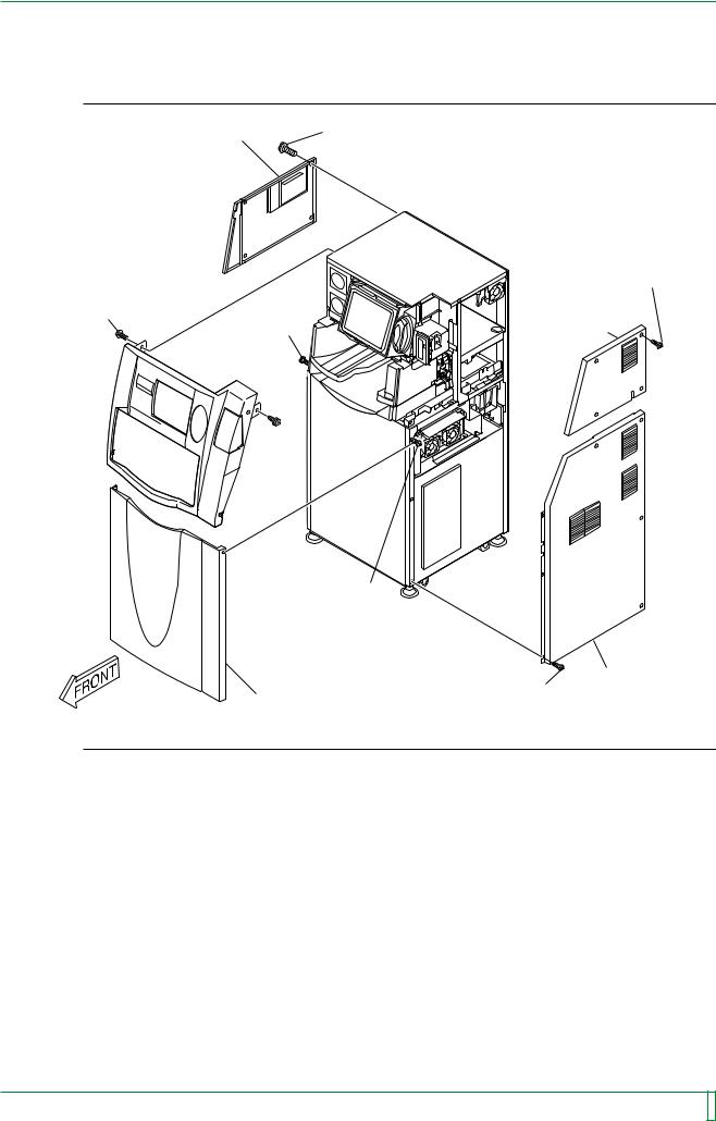
 REFERENCE
Upper left-hand side cover |
#1 |
|
[Remove] T4x12 (x4) |
||
|
|
|
#2 |
|
|
[Remove] |
|
|
T4x6 (x4) |
#4 |
#3 |
Upper right- |
[Remove] |
hand side cover |
|
BR4x8 (x2) |
[Loosen] |
|
|
T4x12 (x2) |
|
Upper front cover 
#5
[Loosen] T4x12 (x2)
|
|
Lower right-hand |
Lower front cover |
#6 |
side cover |
[Remove] T4x6 (x7) |
|
|
|
|
|
|
|
FR7H3308.EPS |
009-058-00 10.20.2000 FM2732 (2)
CR-IR347 Service Manual |
MC - 21 |
|
|
|
|

MC - 22
(2) Disconnect the connectors.
[Disconnect] Connectors
IP removal unit
CNL2
CNL3
|
CNL1 |
|
FRONT |
[Disconnect] Connectors |
|
Cassette set unit |
|
CNU1 |
|
CNK1 |
CNSOLK1 |
|
BCR08A CN1 |
CNK2 |
|
|
FR7H3309.EPS |
009-058-00 10.20.2000 FM2732 (2)
CR-IR347 Service Manual |
MC - 22 |
|
|
|
|
MC - 23
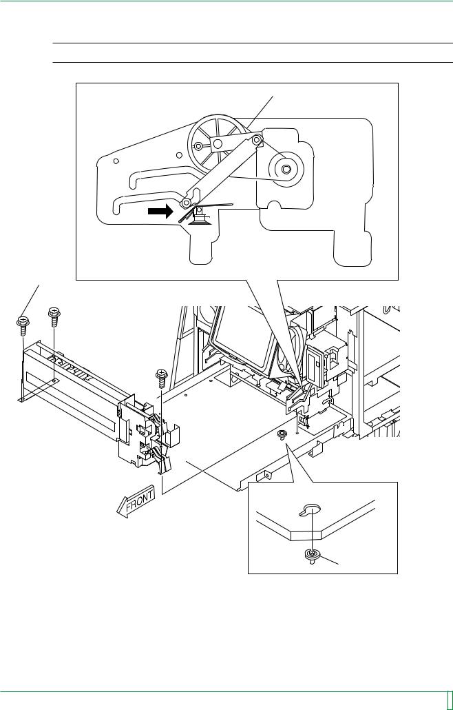
(3) Pull out the tray.
#1 [Loosen] BR4x8 (x2)
 Bracket
#2 [Remove] BR4x8 (x2), W6
#3 [Remove] BR4x8 (x2)
 FRONT
FRONT
#4  [Pull out] Tray
FR7H3389.EPS
009-058-00 10.20.2000 FM2732 (2)
CR-IR347 Service Manual |
MC - 23 |
|
|
|
|
Loading...