


 Loading...
1
AT Command Manual
for
Brodersen Products with Siemens MC55 Modem Engine
V. 04.00 / April 2006 / Doc 40232
Brodersen Controls A/S ● Industrivej 3 ● DK-4000 Roskilde ● Tel: +45 46 74 00 00 ● Fax: +45 46 75 73 36 E-mail: bc@brodersencontrols.com ● Internet: www.brodersencontrols.com

Document Name: |
MC55 AT Command Set |
|
|
Version: |
04.00 |
Date: |
March 17, 2006 |
DocId: |
MC55_ATC_V04.00 |
Status |
Confidential / Released |
|
|
General Notes
Product is deemed accepted by recipient and is provided without interface to recipient’s products. The documentation and/or product are provided for testing, evaluation, integration and information purposes. The documentation and/or product are provided on an “as is” basis only and may contain deficiencies or inadequacies. The documentation and/or product are provided without warranty of any kind, express or implied. To the maximum extent permitted by applicable law, Siemens further disclaims all warranties, including without limitation any implied warranties of merchantability, completeness, fitness for a particular purpose and non-infringement of thirdparty rights. The entire risk arising out of the use or performance of the product and documentation remains with recipient. This product is not intended for use in life support appliances, devices or systems where a malfunction of the product can reasonably be expected to result in personal injury. Applications incorporating the described product must be designed to be in accordance with the technical specifications provided in these guidelines. Failure to comply with any of the required procedures can result in malfunctions or serious discrepancies in results. Furthermore, all safety instructions regarding the use of mobile technical systems, including GSM products, which also apply to cellular phones must be followed. Siemens or its suppliers shall, regardless of any legal theory upon which the claim is based, not be liable for any consequential, incidental, direct, indirect, punitive or other damages whatsoever (including, without limitation, damages for loss of business profits, business interruption, loss of business information or data, or other pecuniary loss) arising out the use of or inability to use the documentation and/or product, even if Siemens has been advised of the possibility of such damages. The foregoing limitations of liability shall not apply in case of mandatory liability, e.g. under the German Product Liability Act, in case of intent, gross negligence, injury of life, body or health, or breach of a condition which goes to the root of the contract. However, claims for damages arising from a breach of a condition, which goes to the root of the contract, shall be limited to the foreseeable damage, which is intrinsic to the contract, unless caused by intent or gross negligence or based on liability for injury of life, body or health. The above provision does not imply a change on the burden of proof to the detriment of the recipient. Subject to change without notice at any time. The interpretation of this general note shall be governed and construed according to German law without reference to any other substantive law.
Copyright
Transmittal, reproduction, dissemination and/or editing of this document as well as utilization of its contents and communication thereof to others without express authorization are prohibited. Offenders will be held liable for payment of damages. All rights created by patent grant or registration of a utility model or design patent are reserved.
Copyright © Siemens AG 2006
MC55_ATC_V04.00 |
Page 2 of 475 |
3/17/06 |
Confidential / Released |
|
|

Contents
1. |
Introduction............................................................................................................................................ |
|
13 |
|
|
1.1 |
Scope of the document ................................................................................................................. |
13 |
|
|
1.2 |
Related documents ....................................................................................................................... |
14 |
|
|
1.3 |
Document conventions.................................................................................................................. |
15 |
|
|
|
1.3.1 |
Quick reference table..................................................................................................... |
15 |
|
|
1.3.2 |
Superscript notation for parameters and values ............................................................ |
16 |
|
1.4 |
AT Command Syntax .................................................................................................................... |
17 |
|
|
|
1.4.1 |
Using Parameters .......................................................................................................... |
17 |
|
|
1.4.2 |
Combining AT commands on the same command line ................................................. |
18 |
|
1.5 |
Supported character sets .............................................................................................................. |
19 |
|
|
|
1.5.1 |
GSM alphabet tables and UCS2 character values ........................................................ |
21 |
|
|
1.5.2 |
UCS2 and GSM data coding and conversion for SMS text mode ................................. |
23 |
|
|
1.5.2.1 |
Implementing output of SIM data to Terminal (direction TA to TE) ................................ |
23 |
|
|
1.5.2.2 |
Implementing input of Terminal data to SIM (direction TE to TA)................................... |
24 |
|
1.6 |
Serial Interface Flow Control ......................................................................................................... |
25 |
|
|
|
1.6.1 |
Software Flow Control (XON/OFF Handshake)............................................................. |
25 |
|
|
1.6.2 |
Hardware Flow Control (RTS/CTS Handshake) ............................................................ |
25 |
|
1.7 |
Unsolicited Result Code Presentation........................................................................................... |
26 |
|
|
|
1.7.1 |
Communication between Customer Application and MC55 .......................................... |
26 |
|
1.8 |
Common PCN Handset Specification (CPHS) .............................................................................. |
27 |
|
|
1.9 |
Errors and Messages .................................................................................................................... |
28 |
|
2. |
Configuration Commands..................................................................................................................... |
29 |
|||
|
2.1 |
AT&F |
Set all current parameters to manufacturer defaults ......................................................... |
29 |
|
|
2.2 |
AT&V |
Display current configuration ............................................................................................ |
30 |
|
|
|
2.2.1 |
AT&V responses............................................................................................................ |
31 |
|
|
2.3 |
AT&W Stores current configuration to user defined profile ......................................................... |
32 |
||
|
2.4 |
ATQ |
Set result code presentation mode ..................................................................................... |
33 |
|
|
2.5 |
ATV |
Set result code format mode ............................................................................................... |
34 |
|
|
|
2.5.1 |
Verbose and numeric result codes ................................................................................ |
34 |
|
|
2.6 |
ATX |
Set CONNECT result code format and call monitoring ....................................................... |
35 |
|
|
2.7 |
ATZ |
Set all current parameters to user defined profile................................................................ |
36 |
|
|
2.8 |
AT+CFUN |
Set phone functionality .............................................................................................. |
37 |
|
|
|
2.8.1 |
Wake up the ME from SLEEP mode ............................................................................. |
40 |
|
|
2.9 |
AT^SMSO |
Switch off mobile station............................................................................................ |
42 |
|
|
2.10 |
AT+GCAP |
Request complete TA capabilities list........................................................................ |
43 |
|
|
2.11 |
AT+CMEE |
Mobile Equipment Error Message Format ................................................................ |
44 |
|
|
|
2.11.1 CME/CMS Error Code Overview ................................................................................... |
45 |
||
|
2.12 |
AT+CSCS |
Select TE character set ............................................................................................. |
49 |
|
|
2.13 |
AT^SCFG |
Extended Configuration Settings ............................................................................... |
50 |
|
|
2.14 |
AT^SM20 |
Set M20 compatibility mode ....................................................................................... |
59 |
|
3. |
Status Control Commands ................................................................................................................... |
60 |
||||
|
|
3.1 |
AT+CMER |
Mobile Equipment Event Reporting .......................................................................... |
60 |
|
|
|
3.2 |
AT+CIND |
Indicator control .......................................................................................................... |
62 |
|
|
|
3.3 |
AT^SIND |
Extended Indicator Control.......................................................................................... |
65 |
|
|
|
|
|
|
||
MC55_ATC_V04.00 |
Page 3 of 475 |
3/17/06 |
|
|||
Confidential / Released |
|
|
|
|||

|
|
3.4 |
AT+CEER |
Extended Error Report............................................................................................... |
71 |
|||
|
|
|
3.4.1 |
|
Cause Location ID for the extended error report ........................................................... |
72 |
||
|
|
|
3.4.2 |
|
GSM release cause for L3 Radio Resource (RR).......................................................... |
73 |
||
|
|
|
3.4.3 |
|
SIEMENS release cause for L3 Radio Resource (RR).................................................. |
73 |
||
|
|
|
3.4.4 |
|
GSM release cause for Mobility Management (MM) or Session Management (SM)..... 74 |
|||
|
|
|
3.4.5 |
|
SIEMENS release cause for L3 Mobility Management (MM) ........................................ |
75 |
||
|
|
|
3.4.6 |
|
GSM release cause for L3 Call Control (CC)................................................................. |
75 |
||
|
|
|
3.4.7 |
|
SIEMENS release cause for L3 Call Control (CC)......................................................... |
77 |
||
|
|
|
3.4.8 |
|
SIEMENS release cause for L3 Advice of Charge (AOC) ............................................. |
77 |
||
|
|
|
3.4.9 |
|
GSM Release cause for Supplementary Service Call ................................................... |
77 |
||
|
|
|
3.4.10 SIEMENS release cause for Call-related Supplementary Services (CRSS) ................. |
79 |
||||
|
|
|
3.4.11 |
|
SIEMENS release cause for Session Management (SM) ............................................. |
80 |
||
|
|
|
3.4.12 |
|
GSM cause for L3 Protocol module or other local cause ............................................. |
80 |
||
|
|
|
3.4.13 |
|
SIEMENS release cause for GPRS API ........................................................................ |
80 |
||
|
|
|
3.4.14 |
|
SIEMENS release cause for PPP/IP-Stack ................................................................... |
80 |
||
|
|
3.5 |
ATS18 |
Extended call release report............................................................................................ |
81 |
|||
|
|
3.6 |
AT+CPAS |
Mobile equipment activity status................................................................................ |
83 |
|||
|
|
3.7 |
AT+WS46 |
Select wireless network ............................................................................................. |
84 |
|||
4. |
Serial Interface Control Commands..................................................................................................... |
85 |
||||||
|
|
4.1 |
AT\Q |
Flow control........................................................................................................................ |
85 |
|||
|
|
4.2 |
AT&C |
Set Data Carrier Detect (DCD) Line mode ....................................................................... |
86 |
|||
|
|
4.3 |
AT&D |
Set circuit Data Terminal Ready (DTR) function mode..................................................... |
87 |
|||
|
|
4.4 |
AT&S |
Set circuit Data Set Ready (DSR) function mode ............................................................. |
88 |
|||
|
|
4.5 |
ATE Enable command echo........................................................................................................ |
89 |
||||
|
|
4.6 |
AT+ILRR |
Set TE-TA local rate reporting..................................................................................... |
90 |
|||
|
|
4.7 |
AT+IPR |
Set fixed local rate ......................................................................................................... |
92 |
|||
|
|
|
4.7.1 |
|
Autobauding................................................................................................................... |
93 |
||
|
|
4.8 |
AT+CMUX |
Enter multiplex mode ................................................................................................ |
95 |
|||
|
|
|
4.8.1 |
|
Restrictions on Multiplex mode...................................................................................... |
96 |
||
|
|
|
4.8.2 |
|
Second serial interface ASC1........................................................................................ |
98 |
||
5. |
Security Commands.............................................................................................................................. |
99 |
||||||
|
|
5.1 |
AT+CPIN |
|
PIN Authentication ...................................................................................................... |
99 |
||
|
|
|
5.1.1 |
|
What to do if PIN or password authentication fails? .................................................... |
101 |
||
|
|
5.2 |
AT+CPIN2 |
PIN2 Authentication ................................................................................................ |
103 |
|||
|
|
5.3 |
AT^SPIC |
Display PIN counter................................................................................................... |
105 |
|||
|
|
5.4 |
AT+CLCK |
Facility lock .............................................................................................................. |
109 |
|||
|
|
5.5 |
AT^SLCK |
Facility lock ............................................................................................................... |
114 |
|||
|
|
5.6 |
AT+CPWD |
Change Password .................................................................................................. |
115 |
|||
|
|
5.7 |
AT^SPWD |
Change Password................................................................................................... |
119 |
|||
6. |
Identification Commands.................................................................................................................... |
120 |
||||||
|
|
6.1 |
ATI Display product identification information ........................................................................... |
120 |
||||
|
|
6.2 |
AT+CGMI |
Request manufacturer identification......................................................................... |
121 |
|||
|
|
6.3 |
AT+GMI |
Request manufacturer identification ........................................................................... |
121 |
|||
|
|
6.4 |
AT+CGMM |
Request model identification .................................................................................. |
122 |
|||
|
|
6.5 |
AT+GMM |
|
Request model identification..................................................................................... |
122 |
||
|
|
6.6 |
AT+CGMR |
Request revision identification of software status................................................... |
123 |
|||
|
|
6.7 |
AT+GMR |
|
Request revision identification of software status ..................................................... |
123 |
||
|
|
|
|
|
|
|||
MC55_ATC_V04.00 |
|
Page 4 of 475 |
3/17/06 |
|
||||
Confidential / Released |
|
|
|
|||||

|
|
6.8 |
AT+CGSN |
|
Request International Mobile Equipment Identity (IMEI)......................................... |
124 |
||
|
|
6.9 |
AT+GSN |
Request International Mobile Equipment Identity (IMEI) ........................................... |
124 |
|||
|
|
6.10 |
AT+CIMI |
Request International Mobile Subscriber Identity (IMSI)............................................ |
125 |
|||
7. |
Call related Commands....................................................................................................................... |
126 |
||||||
|
|
7.1 |
Call Status Information ................................................................................................................ |
126 |
||||
|
|
7.2 |
ATA |
Answer a call ..................................................................................................................... |
127 |
|||
|
|
7.3 |
ATD |
Mobile originated call to specified number ........................................................................ |
128 |
|||
|
|
7.4 |
ATD><mem><n> Mobile originated call using specific memory and index number ................. |
130 |
||||
|
|
7.5 |
ATD><n> |
Mobile originated call from active memory using index number ............................... |
132 |
|||
|
|
7.6 |
ATD><str> |
Mobile originated call from active memory using corresponding field .................... |
133 |
|||
|
|
7.7 |
ATDI |
Mobile originated call to ISDN number............................................................................. |
134 |
|||
|
|
7.8 |
ATDL |
Redial last number used ................................................................................................. |
135 |
|||
|
|
7.9 |
ATH |
Disconnect existing connection......................................................................................... |
136 |
|||
|
|
7.10 |
AT+CHUP |
|
Hang up call ............................................................................................................ |
137 |
||
|
|
7.11 |
ATS0 |
Set number of rings before automatically answering a call ............................................. |
138 |
|||
|
|
7.12 |
ATS6 |
Set pause before blind dialing ......................................................................................... |
139 |
|||
|
|
7.13 |
ATS7 |
Set number of seconds to wait for connection completion .............................................. |
140 |
|||
|
|
7.14 |
ATS8 |
Set number of seconds to wait for comma dialing modifier............................................. |
141 |
|||
|
|
7.15 |
ATS10 Set disconnect delay after indicating the absence of data carrier ................................. |
142 |
||||
|
|
7.16 |
ATO |
Switch from command mode to data mode / PPP online mode........................................ |
143 |
|||
|
|
7.17 |
+++ Switch from data mode to command mode ....................................................................... |
144 |
||||
|
|
7.18 |
AT+CBST |
Select bearer service type ....................................................................................... |
145 |
|||
|
|
7.19 |
AT+CRLP |
Select radio link protocol parameters for originated non-transparent data calls ...... |
146 |
|||
|
|
7.20 |
AT+CLCC |
List current calls of ME ............................................................................................ |
147 |
|||
|
|
7.21 |
AT^SLCC |
Siemens defined command to list current calls of ME.............................................. |
149 |
|||
|
|
7.22 |
AT+CR Service reporting control .............................................................................................. |
155 |
||||
|
|
7.23 |
AT+CRC |
Set Cellular Result Codes for incoming call indication .............................................. |
156 |
|||
|
|
7.24 |
AT+CSNS |
Single Numbering Scheme...................................................................................... |
157 |
|||
|
|
7.25 |
AT^SCNI |
List Call Number Information..................................................................................... |
158 |
|||
|
|
7.26 |
AT^SLCD |
Display Last Call Duration ........................................................................................ |
159 |
|||
|
|
7.27 |
AT^STCD |
Display Total Call Duration....................................................................................... |
160 |
|||
|
|
7.28 |
ATP |
Select pulse dialing ........................................................................................................... |
161 |
|||
|
|
7.29 |
ATT |
Select tone dialing ............................................................................................................. |
161 |
|||
8. |
Network Service Commands .............................................................................................................. |
162 |
||||||
|
|
8.1 |
AT+COPN |
|
Read operator names ............................................................................................. |
162 |
||
|
|
8.2 |
AT+COPS |
|
Operator Selection .................................................................................................. |
163 |
||
|
|
8.3 |
AT^SOPS |
Extended Operator Selection................................................................................... |
166 |
|||
|
|
8.4 |
AT+CREG |
|
Network registration ................................................................................................ |
168 |
||
|
|
8.5 |
AT+CSQ |
Signal quality ............................................................................................................. |
171 |
|||
|
|
8.6 |
AT^SMONC |
Cell Monitoring...................................................................................................... |
172 |
|||
|
|
8.7 |
AT^SMOND |
Cell Monitoring...................................................................................................... |
174 |
|||
|
|
8.8 |
AT^MONI |
Monitor idle mode and dedicated mode ................................................................... |
177 |
|||
|
|
|
8.8.1 |
AT^MONI responses.................................................................................................... |
178 |
|||
|
|
|
8.8.2 |
Service states .............................................................................................................. |
179 |
|||
|
|
8.9 |
AT^MONP |
|
Monitor neighbour cells ........................................................................................... |
180 |
||
|
|
|
8.9.1 |
AT^MONP responses .................................................................................................. |
181 |
|||
|
|
8.10 |
AT^SMONG |
GPRS Monitor ...................................................................................................... |
182 |
|||
|
|
|
8.10.1 AT^SMONG Cell Info Table......................................................................................... |
183 |
||||
|
|
|
|
|
|
|||
MC55_ATC_V04.00 |
|
Page 5 of 475 |
3/17/06 |
|
||||
Confidential / Released |
|
|
|
|
||||

|
|
8.11 |
AT^SALS |
|
Alternate Line Service............................................................................................... |
184 |
|
|
8.12 |
AT^SHOM |
Display Homezone .................................................................................................. |
186 |
|
|
|
8.13 |
AT^SPLM |
Read the PLMN list .................................................................................................. |
187 |
|
|
|
8.14 |
AT+CPOL |
Preferred Operator List ............................................................................................ |
188 |
|
|
|
8.15 |
AT^SPLR |
Read entry from the preferred operators list............................................................. |
189 |
|
|
|
8.16 |
AT^SPLW |
Write an entry to the preferred operators list ........................................................... |
190 |
|
9. |
Supplementary Service Commands .................................................................................................. |
191 |
||||
|
|
9.1 |
AT+CACM |
Accumulated call meter (ACM) reset or query ........................................................ |
191 |
|
|
|
9.2 |
AT^SACM |
Advice of charge and query of ACM and ACMmax ................................................. |
192 |
|
|
|
9.3 |
AT+CAMM |
Accumulated call meter maximum (ACMmax) set or query.................................... |
194 |
|
|
|
9.4 |
AT+CAOC |
Advice of Charge information.................................................................................. |
195 |
|
|
|
9.5 |
AT+CCUG |
Closed User Group ................................................................................................. |
196 |
|
|
|
9.6 |
AT+CCFC |
Call forwarding number and conditions control ....................................................... |
198 |
|
|
|
9.7 |
AT+CCWA |
Call Waiting ............................................................................................................ |
202 |
|
|
|
9.8 |
AT+CHLD |
Call Hold and Multiparty........................................................................................... |
206 |
|
|
|
9.9 |
AT+CLIP |
|
Calling Line Identification Presentation ..................................................................... |
208 |
|
|
9.10 |
AT+CLIR |
|
Calling line identification restriction ........................................................................... |
210 |
|
|
9.11 |
AT+COLP |
Connected Line Identification Presentation ............................................................. |
211 |
|
|
|
9.12 |
AT+CPUC |
Price per unit and currency table............................................................................. |
213 |
|
|
|
9.13 |
AT+CSSN |
Supplementary service notifications ........................................................................ |
215 |
|
|
|
9.14 |
AT+CUSD |
Supplementary service notifications........................................................................ |
217 |
|
10. |
Internet Service Commands ............................................................................................................... |
219 |
||||
|
|
10.1 |
AT^SICS |
|
Internet Connection Setup Profile.............................................................................. |
222 |
|
|
|
10.1.1 Example: Default values of a CSD connection profile ................................................. |
224 |
||
|
|
|
10.1.2 Example: GPRS connection profile ............................................................................. |
225 |
||
|
|
10.2 |
AT^SICI |
Internet Connection Information.................................................................................. |
226 |
|
|
|
|
10.2.1 Checking Connection Profile Status ............................................................................ |
227 |
||
|
|
10.3 |
AT^SISS |
|
Internet Service Setup Profile .................................................................................... |
228 |
|
|
10.4 |
AT^SISI |
Internet Service Information ........................................................................................ |
237 |
|
|
|
10.5 |
AT^SISO |
|
Internet Service Open ............................................................................................... |
239 |
|
|
|
10.5.1 Example: Accepting / Rejecting Socket Connection Request from Remote Client |
..... 242 |
||
|
|
10.6 |
AT^SISC |
|
Internet Service Close ............................................................................................... |
244 |
|
|
10.7 |
AT^SISR |
|
Internet Service Read Data ....................................................................................... |
245 |
|
|
|
10.7.1 |
Example: Socket Host Reads Small Amounts of UDP Data Packets (URC Mode)..... 246 |
||
|
|
10.8 |
AT^SISW |
|
Internet Service Write Data....................................................................................... |
248 |
|
|
|
10.8.1 Usage of parameter <eodFlag>................................................................................... |
250 |
||
|
|
10.9 |
AT^SISE |
|
Internet Service Error Report..................................................................................... |
251 |
|
|
10.10 Internet Service URC "^SIS" ....................................................................................................... |
252 |
|||
|
|
|
10.10.1 Information Elements Related to the Service Application............................................ |
253 |
||
|
|
|
10.10.2 Information Elements Related to FTP Service............................................................. |
254 |
||
|
|
|
10.10.3 Information Elements Related to HTTP Service .......................................................... |
255 |
||
|
|
|
10.10.4 Information Elements Related to POP3 Service.......................................................... |
255 |
||
|
|
|
10.10.5 Information Elements Related to SMTP Service ......................................................... |
255 |
||
|
|
10.11 |
Examples of how to Configure and Use Internet Service Profiles............................................... |
256 |
||
|
|
|
10.11.1 Selecting URC Mode or Polling Mode ......................................................................... |
256 |
||
|
|
|
10.11.2 |
Configuring Socket Listener......................................................................................... |
256 |
|
|
|
|
10.11.3 Configuring Socket Client for Calling a Socket Listener on Another Host ................... |
257 |
||
|
|
|
10.11.4 Socket Client Sends Data via TCP Connection (Polling Mode)................................... |
257 |
||
|
|
|
|
|
||
MC55_ATC_V04.00 |
|
Page 6 of 475 |
3/17/06 |
|||
Confidential / Released |
|
|
||||

|
|
|
10.11.5 Socket client sends data via TCP connection with URCs............................................ |
258 |
|||||
|
|
|
10.11.6 Configuring and Using FTP Download (URC Mode) ................................................... |
258 |
|||||
|
|
|
10.11.7 Configuring and Using FTP Upload (URC Mode)........................................................ |
259 |
|||||
|
|
|
10.11.8 Configuring SMPT Service Profile ............................................................................... |
259 |
|||||
|
|
|
10.11.9 Sending Email (URC Mode) ........................................................................................ |
260 |
|||||
|
|
|
10.11.10 Sending Email (Polling Mode) ..................................................................................... |
261 |
|||||
|
|
|
10.11.11 Configuring POP3 Service Profile................................................................................ |
262 |
|||||
|
|
|
10.11.12 Retrieving Email (URC Mode) ..................................................................................... |
262 |
|||||
|
|
|
10.11.13 Retrieving Email (Polling Mode) .................................................................................. |
263 |
|||||
|
|
|
10.11.14 HTTP POST (Polling Mode) ........................................................................................ |
264 |
|||||
|
|
|
10.11.15 HTTP GET (Polling Mode)........................................................................................... |
265 |
|||||
11. |
GPRS Commands................................................................................................................................ |
|
|
266 |
|||||
|
|
11.1 |
AT+CGACT |
PDP context activate or deactivate ....................................................................... |
266 |
||||
|
|
11.2 |
AT+CGANS |
Manual response to a network request for PDP context activation ...................... |
268 |
||||
|
|
11.3 |
AT+CGATT GPRS attach or detach ......................................................................................... |
270 |
|||||
|
|
11.4 |
AT+CGAUTO |
|
Automatic response to a network request for PDP context activation ............... |
271 |
|||
|
|
11.5 |
AT+CGEREP |
|
GPRS event reporting ........................................................................................ |
273 |
|||
|
|
11.6 |
AT+CGDATA |
Enter data state .................................................................................................. |
275 |
||||
|
|
|
11.6.1 Automatic deactivation of PDP context during dial-up PPP......................................... |
276 |
|||||
|
|
11.7 |
AT+CGDCONT |
Define PDP Context ........................................................................................ |
277 |
||||
|
|
11.8 |
AT+CGPADDR |
Show PDP address ......................................................................................... |
279 |
||||
|
|
11.9 |
AT+CGQMIN |
Quality of Service Profile (Minimum acceptable) ................................................ |
280 |
||||
|
|
11.10 |
AT+CGQREQ |
Quality of Service Profile (Requested) .............................................................. |
284 |
||||
|
|
11.11 |
AT+CGREG |
GPRS Network Registration Status...................................................................... |
288 |
||||
|
|
11.12 |
AT+CGSMS |
Select service for MO SMS messages................................................................. |
290 |
||||
|
|
11.13 |
AT^SGAUTH |
Set type of authentication for PPP connection.................................................... |
291 |
||||
|
|
11.14 |
AT^SGCONF |
Configuration of GPRS related Parameters ...................................................... |
292 |
||||
|
|
11.15 |
ATA |
Manual response to a network request for PDP context activation................................... |
293 |
||||
|
|
11.16 ATD*99# |
Request GPRS service.............................................................................................. |
294 |
|||||
|
|
11.17 ATD*98# |
Request GPRS IP service ......................................................................................... |
295 |
|||||
|
|
11.18 |
ATH |
Manual rejection of a network request for PDP context activation.................................... |
296 |
||||
|
|
11.19 |
ATS0 |
Automatic response to a network request for PDP context activation............................. |
297 |
||||
|
|
11.20 |
Using GPRS AT commands (Examples)..................................................................................... |
298 |
|||||
|
|
11.21 |
Using the GPRS dial command ATD .......................................................................................... |
300 |
|||||
12. |
FAX Commands................................................................................................................................... |
|
|
301 |
|||||
|
|
12.1 |
FAX parameters .......................................................................................................................... |
301 |
|||||
|
|
|
12.1.1 Summary of Fax Class 2 URCs defined by EIA PN-2388 ........................................... |
303 |
|||||
|
|
12.2 |
AT+FBADLIN |
|
Bad Line Threshold ............................................................................................ |
304 |
|||
|
|
12.3 |
AT+FBADMUL |
Error Threshold Multiplier ................................................................................. |
305 |
||||
|
|
12.4 |
AT+FBOR |
Query data Bit Order ............................................................................................... |
306 |
||||
|
|
12.5 |
AT+FCIG |
Query or set the Local Polling ID .............................................................................. |
307 |
||||
|
|
12.6 |
AT+FCLASS |
Fax: Select, read or test service class................................................................. |
308 |
||||
|
|
12.7 |
AT+FCQ |
Copy Quality Checking .............................................................................................. |
309 |
||||
|
|
12.8 |
AT+FCR |
Capability to Receive ................................................................................................. |
310 |
||||
|
|
12.9 |
AT+FDCC |
Query or set capabilities .......................................................................................... |
311 |
||||
|
|
12.10 |
AT+FDFFC Data Compression Format Conversion ................................................................. |
312 |
|||||
|
|
12.11 AT+FDIS |
Query or set session parameters .............................................................................. |
313 |
|||||
|
|
12.12 |
AT+FDR |
Begin or continue phase C Data Reception ............................................................... |
314 |
||||
|
|
|
|
|
|
|
|||
MC55_ATC_V04.00 |
|
|
Page 7 of 475 |
3/17/06 |
|
||||
Confidential / Released |
|
|
|
|
|
||||

12.13 |
AT+FDT |
Data Transmission...................................................................................................... |
315 |
|
12.14 |
AT+FET |
End a page or document ............................................................................................ |
316 |
|
12.15 |
AT+FK Kill operation, orderly FAX abort ................................................................................... |
317 |
||
12.16 |
AT+FLID |
Query or set the Local Id setting capabilities ............................................................. |
318 |
|
12.17 |
AT+FMDL |
|
Identify Product Model ............................................................................................ |
319 |
12.18 |
AT+FMFR |
Request Manufacturer Identification........................................................................ |
320 |
|
12.19 |
AT+FOPT |
|
Set bit Order independently ..................................................................................... |
321 |
12.20 |
AT+FPHCTO DTE Phase C Response Timeout....................................................................... |
322 |
||
12.21 |
AT+FREV |
|
Identify Product Revision ......................................................................................... |
323 |
12.22 |
AT+FRH |
Receive Data Using HDLC Framing .......................................................................... |
324 |
|
12.23 |
AT+FRM |
Receive Data ............................................................................................................. |
325 |
|
12.24 |
AT+FRS |
Receive Silence.......................................................................................................... |
326 |
|
12.25 |
AT+FTH |
Transmit Data Using HDLC Framing.......................................................................... |
327 |
|
12.26 |
AT+FTM |
Transmit Data............................................................................................................. |
328 |
|
12.27 |
AT+FTS |
Stop Transmission and Wait....................................................................................... |
329 |
|
12.28 |
AT+FVRFC |
Vertical Resolution Format Conversion ................................................................. |
330 |
|
13. Short Message Service (SMS) Commands........................................................................................ |
331 |
|||
13.1 |
SMS parameters ......................................................................................................................... |
331 |
||
13.2 |
AT+CMGC |
Send an SMS command......................................................................................... |
335 |
|
13.3 |
AT+CMGD |
Delete short message............................................................................................. |
336 |
|
13.4 |
AT+CMGF |
Select SMS message format .................................................................................. |
337 |
|
13.5 |
AT+CMGL |
List SMS messages from preferred store................................................................ |
338 |
|
13.6 |
AT+CMGR |
Read SMS messages............................................................................................. |
340 |
|
13.7 |
AT+CMGS |
Send Short Message .............................................................................................. |
342 |
|
13.8 |
AT+CMGW |
Write Short Messages to Memory ......................................................................... |
344 |
|
13.9 |
AT+CMSS |
Send short messages from storage ........................................................................ |
346 |
|
13.10 |
AT+CNMA |
New Message Acknowledgement to ME/TE, only phase 2+ .................................. |
347 |
|
13.11 |
AT+CNMI |
|
New short Message Indication ................................................................................. |
348 |
13.12 |
AT+CPMS |
Preferred SMS message storage............................................................................ |
351 |
|
13.13 |
AT+CSCA |
SMS Service Center Address.................................................................................. |
353 |
|
13.14 |
AT+CSCB |
Select Cell Broadcast Message Indication .............................................................. |
354 |
|
13.15 |
AT+CSDH |
Show SMS text mode parameters........................................................................... |
355 |
|
13.16 |
AT+CSMP |
Set SMS text Mode Parameters.............................................................................. |
356 |
|
13.17 |
AT+CSMS |
Select Message Service.......................................................................................... |
358 |
|
13.18 |
AT^SLMS |
|
List SMS Memory Storage ....................................................................................... |
360 |
13.19 |
AT^SMGL |
|
List Short Messages from preferred store without setting status to REC READ ..... |
361 |
13.20 |
AT^SMGO |
Set or query SMS overflow presentation mode or query SMS overflow ................. |
362 |
|
13.21 |
AT^SMGR |
Read short message without setting status to REC READ..................................... |
364 |
|
13.22 |
AT^SSCONF SMS Command Configuration ........................................................................... |
365 |
||
13.23 |
AT^SSDA |
|
Set SMS Display Availability .................................................................................... |
366 |
13.24 |
AT^SSMSS |
Set Short Message Storage Sequence ................................................................. |
367 |
|
14. SIM related Commands....................................................................................................................... |
368 |
|||
14.1 |
AT+CRSM |
Restricted SIM Access............................................................................................ |
368 |
|
14.2 |
AT^SXSM |
|
Extended SIM Access.............................................................................................. |
370 |
14.3 |
AT^SCKS |
|
Query SIM and Chip Card Holder Status ................................................................. |
372 |
14.4 |
AT^SCID |
Display SIM card identification number ..................................................................... |
374 |
|
14.5 |
AT+CXXCID Display card ID..................................................................................................... |
375 |
||
MC55_ATC_V04.00 |
Page 8 of 475 |
3/17/06 |
Confidential / Released |
|
|

15. SIM Application Toolkit (SAT) Commands........................................................................................ |
376 |
||
15.1 |
AT^SSTA |
SAT Interface Activation ........................................................................................... |
376 |
15.2 |
^SSTN SAT Notification ............................................................................................................ |
378 |
|
15.3 |
AT^SSTGI |
SAT Get Information ............................................................................................... |
379 |
15.4 |
AT^SSTR |
SAT Response ......................................................................................................... |
380 |
16. Phonebook Commands....................................................................................................................... |
381 |
||
16.1 |
Sort Order for Phonebooks ......................................................................................................... |
381 |
|
16.2 |
AT+CPBR |
Read from Phonebook............................................................................................. |
382 |
16.3 |
AT+CPBS |
Select phonebook memory storage ......................................................................... |
385 |
16.4 |
AT+CPBW |
Write into Phonebook ............................................................................................. |
387 |
16.5 |
AT^SPBC |
Find first matching entry in sorted phonebook ......................................................... |
390 |
16.6 |
AT^SPBD |
Purge phonebook memory storage.......................................................................... |
391 |
16.7 |
AT^SPBG |
Display phonebook entries in alphabetical order ..................................................... |
392 |
16.8 |
AT^SPBS |
Step through the selected phonebook alphabetically............................................... |
395 |
16.9 |
AT+CNUM |
Read own numbers................................................................................................. |
399 |
16.10 |
AT^SDLD |
Delete the 'last number redial' memory .................................................................... |
400 |
17. Audio Commands ................................................................................................................................ |
401 |
||||
17.1 |
Audio programming model .......................................................................................................... |
401 |
|||
17.2 |
ATL |
Set monitor speaker loudness ........................................................................................... |
402 |
||
17.3 |
ATM |
Set monitor speaker mode................................................................................................ |
402 |
||
17.4 |
AT+CLVL |
|
Loudspeaker volume level........................................................................................ |
403 |
|
17.5 |
AT+CMUT |
Mute control ............................................................................................................ |
404 |
||
17.6 |
AT+VTD |
Tone duration ............................................................................................................. |
405 |
||
17.7 |
AT+VTS |
DTMF and tone generation......................................................................................... |
406 |
||
17.8 |
AT^SAIC |
|
Audio Interface Configuration .................................................................................... |
407 |
|
17.9 |
AT^SNFA |
|
Set or query of microphone attenuation .................................................................. |
409 |
|
17.10 |
AT^SNFD |
|
Set audio parameters to manufacturer default values ............................................. |
411 |
|
17.11 |
AT^SNFI |
|
Set microphone path parameters .............................................................................. |
412 |
|
17.12 |
AT^SNFM |
|
Set microphone audio path and power supply......................................................... |
413 |
|
17.13 |
AT^SNFO |
|
Set audio output (= loudspeaker path) parameter ................................................... |
415 |
|
17.14 |
AT^SNFPT Set progress tones ................................................................................................. |
417 |
|||
17.15 |
AT^SNFS |
|
Select audio hardware set........................................................................................ |
418 |
|
17.16 |
AT^SNFTTY Signal TTY/CTM audio mode capability............................................................... |
421 |
|||
17.17 |
AT^SNFV |
|
Set loudspeaker volume........................................................................................... |
422 |
|
17.18 |
AT^SNFW |
Write audio setting in non-volatile store .................................................................. |
423 |
||
17.19 |
AT^SRTC |
|
Ring tone configuration ............................................................................................ |
424 |
|
18. Hardware related Commands............................................................................................................. |
426 |
||
18.1 |
AT+CCLK |
Real Time Clock....................................................................................................... |
426 |
18.2 |
AT+CALA |
Set alarm time ......................................................................................................... |
427 |
18.3 |
AT^SBC |
Battery Charge Control............................................................................................... |
430 |
|
18.3.1 Responses returned by read command....................................................................... |
432 |
|
18.4 |
AT^SBV |
Battery/Supply Voltage ............................................................................................... |
433 |
18.5 |
AT^SCTM |
Set critical operating temperature presentation mode or query temperature........... |
434 |
18.6 |
AT^SSYNC Configure SYNC Pin.............................................................................................. |
437 |
|
|
18.6.1 ME status indicated by status LED patterns ................................................................ |
438 |
|
19. Miscellaneous Commands.................................................................................................................. |
|
439 |
|
|
19.1 A/ Repeat previous command line |
............................................................................................ |
439 |
|
|
|
|
MC55_ATC_V04.00 |
Page 9 of 475 |
3/17/06 |
|
Confidential / Released |
|
|
|

19.2 |
ATS3 |
Set command line termination character......................................................................... |
440 |
19.3 |
ATS4 |
Set response formatting character .................................................................................. |
441 |
19.4 |
ATS5 |
Write command line editing character ............................................................................. |
442 |
20. Appendix .............................................................................................................................................. |
|
443 |
|
20.1 |
Restricted access to SIM data after SIM PIN authentication....................................................... |
443 |
|
20.2 |
Star-Hash (*#) Network Commands............................................................................................ |
444 |
|
20.3 |
Available AT Commands and Dependency on SIM PIN ............................................................. |
447 |
|
20.4 |
Availability of AT Commands Depending on Operating Mode of ME.......................................... |
454 |
|
20.5 |
AT Command Settings storable with AT&W................................................................................ |
461 |
|
20.6 |
Factory Default Settings Restorable with AT&F .......................................................................... |
464 |
|
20.7 |
Summary of Unsolicited Result Codes (URC)............................................................................. |
467 |
|
20.8 |
Alphabetical List of AT Commands ............................................................................................. |
470 |
|
MC55_ATC_V04.00 |
Page 10 of 475 |
3/17/06 |
Confidential / Released |
|
|
List of Tables |
|
|
Table 1.1: |
Symbols used to mark the type of parameters ........................................................................... |
16 |
Table 1.2: |
Symbols used to indicate the correlations with other commands ............................................... |
16 |
Table 1.3: |
Symbols used to mark different types of default values of parameters ..................................... |
16 |
Table 1.4: |
Types of AT commands and responses .................................................................................... |
17 |
Table 1.5: |
Examples for character definitions depending on alphabet ........................................................ |
20 |
Table 2.1: |
Current configuration on ASC0 / MUX channel 1 (example) ...................................................... |
31 |
Table 2.2: |
Current configuration on ASC1 and MUX channels 2 and 3 (example) .................................... |
31 |
Table 2.3: |
Wake-up events in NON-CYCLIC and CYCLIC SLEEP modes ................................................. |
40 |
Table 2.4: |
General "CME ERROR" Codes (GSM 07.07) .......................................................................... |
45 |
Table 2.5: |
General "CME ERROR" Codes (SIEMENS) ............................................................................ |
46 |
Table 2.6: |
GPRS related "CME ERROR" Codes (GSM 07.07) ................................................................. |
46 |
Table 2.7: |
SMS related "CMS ERROR" Codes (GSM 07.05) ................................................................... |
46 |
Table 4.1: |
Availability of AT Commands on Virtual Channels .................................................................... |
96 |
Table 4.2: |
Summary of AT commands with Different Behavior in Multiplex Mode ..................................... |
97 |
Table 10.1: |
Applicability of AT^SICS <conParmTag> values ................................................................... |
222 |
Table 10.2: |
Applicability of AT^SISS <srvParmTag> values ................................................................... |
228 |
Table 12.1: Summary of Fax Class 2 URCs defined by EIA PN-2388 ........................................................ |
303 |
|
Table 18.1: |
Modes of the LED and indicated ME functions......................................................................... |
438 |
Table 20.1: |
Star-Hash (*#) Command Overview ........................................................................................ |
444 |
Table 20.2: |
Abbreviations of Codes and Parameters used in Table 20.1 .................................................. |
445 |
Table 20.3: |
Star-Hash Command Response Parameters .......................................................................... |
446 |
Table 20.4: |
Star-Hash Commands for Supplementary Services ................................................................ |
446 |
Table 20.5: |
Available AT Commands and Dependency on SIM PIN........................................................... |
447 |
Table 20.6: |
Availability of AT Commands Depending on Operating Mode of ME ....................................... |
454 |
Table 20.7: |
Settings Stored to User Profile on ASC0 / MUX Channel 1...................................................... |
461 |
Table 20.8: |
Settings Stored to User Profile on ASC1 / MUX Channels 2 and 3.......................................... |
462 |
Table 20.9: Factory Default Settings Restorable with AT&F ....................................................................... |
464 |
|
Table 20.10: |
Summary of Unsolicited Result Codes (URC) .......................................................................... |
467 |
Table 20.11: |
Alphabetical List of AT Commands........................................................................................... |
470 |
MC55_ATC_V04.00 |
Page 11 of 475 |
3/17/06 |
Confidential / Released |
|
|

List of Figures |
|
|
Figure 1.1: |
Main character table of GSM 03.38 alphabet ............................................................................. |
21 |
Figure 1.2: |
Extension character table of GSM 03.38 alphabet ..................................................................... |
22 |
Figure 17.1: |
Audio programming model for MC55 Module ........................................................................... |
401 |
MC55_ATC_V04.00 |
Page 12 of 475 |
3/17/06 |
Confidential / Released |
|
|

1.Introduction
1.1Scope of the document
This document presents the AT Command Set for the Siemens Cellular Engine
MC55 Release 04.00.
Before using the Cellular Engine or upgrading to a new firmware version please read the latest product information provided in the Release Notes [1].
More information is available at the Siemens Website: http://www.siemens.com/wm.
MC55_ATC_V04.00 |
Page 13 of 475 |
3/17/06 |
Confidential / Released |
|
|

1.2Related documents
[1]MC55 Release Notes, Version 04.00
[2]MC55 Hardware Interface Description, Version 04.00
[3]GPRS Startup User's Guide
[4]Remote-SAT User's Guide
[5]Multiplexer User's Guide
[6]Multiplex Driver Developer's Guide for Windows 2000 and Windows XP
[7]Multiplex Driver Installation Guide for Windows 2000 and Windows XP
[8]Application Note 02: Audio Interface Design
[9]Application Note 16: Updating MC55 Firmware [10] Application Note 24: Application Developer's Guide
[11] Application Note 22: Using TTY / CTM equipment with MC55
[12] ISO/IEC10646: "Universal Multiple-Octet Coded Character Set (UCS)"; UCS2, 16 bit coding
[13]ITU-T Recommendation V.24: List of definitions for interchange circuits between data terminal equipment (DTE) and data circuit-terminating equipment (DCE)
[14]ITU-T Recommendation V.250: Serial asynchronous automatic dialling and control
[15]3GPP TS 100 918/EN 300 918 (GSM 02.04): General on supplementary services
[16]3GPP TS 100 907 (GSM 02.30): Man-Machine Interface (MMI) of the Mobile Station (MS)
[17]3GPP TS 23.038 (GSM 03.38): Alphabets and language specific information
[18]3GPP TS 27.005 (GSM 07.05): Use of Data Terminal Equipment - Data Circuit terminating Equipment (DTE
-DCE) interface for Short Message Service (SMS) and Cell Broadcast Service (CBS)
[19]3GPP TS 27.007 (GSM 07.07): AT command set for User Equipment (UE)
[20]3GPP TS 27.060 (GSM 07.60): Mobile Station (MS) supporting Packet Switched Services
[21]3GPP TS 51.011 (GSM 11.11): Specification of the Subscriber Identity Module - Mobile Equipment (SIM - ME) interface
[22]3GPP TS 11.14 (GSM 11.14): Specification of the SIM Application Toolkit for the Subscriber Identity Module
-Mobile Equipment (SIM - ME) interface
[23]3GPP TS 22.101 (GSM 22.101): Service principles
[24]Common PCN Handset Specification (CPHS) v4.2
MC55_ATC_V04.00 |
Page 14 of 475 |
3/17/06 |
Confidential / Released |
|
|

1.3Document conventions
Throughout the document, the GSM engines are referred to as ME (Mobile Equipment), MS (Mobile Station), TA (Terminal Adapter), DCE (Data Communication Equipment) or facsimile DCE (FAX modem, FAX board).
To control your GSM engine you can simply send AT Commands via its serial interface. The controlling device at the other end of the serial line is referred to as TE (Terminal Equipment), DTE (Data Terminal Equipment) or plainly 'the application' (probably running on an embedded system).
All abbreviations and acronyms used throughout this document are based on the GSM specifications. For definitions please refer to TR 100 350 V7.0.0 (1999-08), (GSM 01.04, version 7.0.0 release 1998).
1.3.1Quick reference table
Each AT command description includes a table similar to the example shown below. The table is intended as a quick reference to indicate the following functions:
PIN: |
Is the AT command PIN protected? |
|
|
% |
Yes |
|
! |
No |
|
§ |
Usage is dependent on conditions specified for the command, or not all command types are PIN |
|
|
protected (for example write command PIN protected, read command not). |
|
Note: The table provided in Section 20.3, Available AT Commands and Dependency on SIM |
|
|
|
PIN uses the same symbols. |
ASC0: |
Is the AT command supported on the first physical serial interface ASC0? |
|
|
% |
Yes |
|
! |
No |
ASC1: |
Is the AT command supported on the second physical serial interface ASC1? |
|
|
% |
Yes |
|
! |
No |
MUXn: |
Is the AT command usable on the Multiplexer channels MUX1, MUX2, MUX3? |
|
%Yes ! No
§ AT command is usable, but under the restrictions specified in the section related to the command. Note: The columns MUX1, MUX2 and MUX3 are relevant only when the GSM engine operates in Multiplexer mode, that is, when the first physical serial interface is partitioned into 3 virtual channels
by using the Multiplexer protocol. Usage is the same on ASC0 and MUX1.
Is the AT command supported in ALARM mode?
%Yes
!No
Charge: Is the AT command supported in CHARGE ONLY mode? % Yes
!No
§AT command is usable, but under the restrictions specified in the section related to the command.
Last: If commands are concatenated, this AT command must be the last one. % Yes
!No
Note: See also Section 1.4, AT Command Syntax for details on concatenated AT commands.
Example:
PIN ASC0 ASC1 MUX1 MUX2 MUX3 Charge Last
! % % § § § % ! !
MC55_ATC_V04.00 |
Page 15 of 475 |
3/17/06 |
Confidential / Released |
|
|

1.3.2Superscript notation for parameters and values
Table 1.1: Symbols used to mark the type of parameters
Parameter type |
Meaning |
|
<param>(num) |
Parameter value must be numeric type |
|
<param>(str) |
Parameter value must be string type |
|
Table 1.2: |
Symbols used to indicate the correlations with other commands |
|
|
|
|
Parameter option |
Meaning |
|
<param>(&W) |
Parameter value will be stored with AT&W |
|
<param>(&V) |
Parameter value will be displayed with AT&V |
|
<param>(ˆSNFW) |
Parameter value will be stored with AT^SNFW |
|
<param>(+CSCS) |
Parameter value has to be (is) coded according to current setting of <chset> (see |
|
|
|
AT+CSCS for details) |
Table 1.3: |
Symbols used to mark different types of default values of parameters |
|
|
|
|
Value option |
Meaning |
|
[x] |
|
Default value: if the parameter is omitted, the value 'x' will be assumed |
x(&F) |
|
Factory default value, will be restored to 'x' with AT&F |
x(P) |
|
Powerup default value of a parameter which is not stored at power down |
x(D) |
|
Delivery default value of a parameter which cannot be restored automatically |
MC55_ATC_V04.00 |
Page 16 of 475 |
3/17/06 |
Confidential / Released |
|
|

1.4AT Command Syntax
The "AT" or "at" prefix must be set at the beginning of each command line. To terminate a command line enter <CR>. Commands are usually followed by a response that includes "<CR><LF><response><CR><LF>". Throughout this document, only the responses are presented, <CR><LF> are omitted intentionally.
Table 1.4: Types of AT commands and responses
AT command type |
Syntax |
Function |
Test command |
AT+CXXX=? |
The mobile equipment returns the list of parameters and value |
|
|
ranges set with the corresponding Write command or by internal |
|
|
processes. |
Read command |
AT+CXXX? |
This command returns the currently set value of the parameter or |
|
|
parameters. |
Write command |
AT+CXXX=<...> |
This command sets user-definable parameter values. |
Exec(ution) command |
AT+CXXX |
The execution command reads non-variable parameters deter- |
|
|
mined by internal processes in the GSM engine. |
1.4.1Using Parameters
•Optional parameters are enclosed in square brackets. If optional parameters are omitted, the current settings are used until you change them.
•Optional parameters or subparameters can be omitted unless they are followed by other parameters. If you want to omit a parameter in the middle of a string it must be replaced by a comma. See also example 1.
•A parameter value enclosed in square brackets represents the value that will be used if an optional parameter is omitted. See also example 2.
•When the parameter is a character string, e.g. <text> or <number>, the string must be enclosed in quotation marks, e.g. "Charlie Brown" or "+49030xxxx". Symbols in quotation marks will be recognized as strings.
•All spaces will be ignored when using strings without quotaton marks.
•It is possible to omit the leading zeros of strings which represent numbers.
•If an optional parameter of a V.250 command is omitted, its value is assumed to be 0.
Example 1: Omitting parameters in the middle of a string
AT+CCUG? |
Query current setting |
+CCUG: 1,10,1 |
|
OK |
Set only the middle parameter |
AT+CCUG=,9 |
|
OK |
Query new setting |
AT+CCUG? |
|
+CCUG: 1,9,1 |
|
OK |
|
Example 2: Using default parameter values for optional parameters |
|
AT+CFUN=5 |
Activate CYCLIC SLEEP mode, don't reset ME |
OK |
Query ME mode |
AT+CFUN? |
|
+CFUN: 5 |
|
OK |
Set ME back to normal (default parameters: 1,0) |
AT+CFUN= |
|
OK +CFUN: 1 OK
MC55_ATC_V04.00 |
Page 17 of 475 |
3/17/06 |
Confidential / Released |
|
|

1.4.2Combining AT commands on the same command line
You may enter several AT commands on the same line. This eliminates the need to type the "AT" or "at" prefix before each command. Instead, it is only needed once at the beginning of the command line. Use a semicolon as command delimiter.
The table below lists the AT commands you cannot enter together with other commands on the same line. Otherwise, the responses may not be in the expected order.
AT command type |
Comment |
V.250 commands |
with FAX commands (Prefix AT+F) |
GSM 7.07 commands |
with Siemens commands, Prefix AT^S) |
GSM 7.05 commands (SMS) |
To be used standalone |
Commands starting with AT& |
To be used standalone |
AT+IPR |
To be used standalone |
|
|
Note: When concatenating AT commands please keep in mind that the sequence of processing may be different from the sequential order of command input. Therefore, if the consecutive order of the issued commands and the associated responses is your concern, avoid concatenating commands on the same line.
MC55_ATC_V04.00 |
Page 18 of 475 |
3/17/06 |
Confidential / Released |
|
|

1.5Supported character sets
The ME supports two character sets: GSM 03.38 (7 bit, also referred to as GSM alphabet or SMS alphabet) and UCS2 (16 bit, refer to ISO/IEC 10646). See AT+CSCS for information about selecting the character set. Character tables can be found below.
Explanation of terms
•International Reference Alphabet (IRA)
IRA means that one byte is displayed as two characters in hexadecimal format. For example, the byte 0x36 (decimal 54) is displayed as "36" (two characters). IRA is used here for input 8-bit or 16-bit data via terminal devices using text mode. This means only characters 'A'..F','a'..'f' and '0'..'9' are valid.
•Escape sequences
The escape sequence used within a text coded in the GSM default alphabet (0x1B) must be correctly interpreted by the TE, both for character input and output. To the module, an escape sequence appears like any other byte received or sent.
•Terminal Adapter (TA)
TA is used equivalent to Mobile Equipment (ME) which stands for the GSM module described here. It uses GSM default alphabet as its character set.
•Terminal Equipment (TE)
TE is the device connected to the TA via serial interface. In most cases TE is an ANSI/ASCII terminal that does not fully support the GSM default alphabet, for example MS Hyperterminal.
•TE Character Set
The character set currently used by Terminal Equipment is selected with AT+CSCS.
•Data Coding Scheme (dcs)
DCS is part of a short message and is saved on the SIM. When writing a short message to the SIM in text mode, the dcs stored with AT+CSMP is used and determines the coded character set.
The behavior when encountering characters, that are not valid characters of the supported alphabets, is undefined.
Due to the constraints described below it is recommended to prefer the USC2 alphabet in any external application.
If the GSM alphabet is selected all characters sent over the serial line (between TE and TA) are in the range from 0 to 127 (7 Bit range). CAUTION: ASCII alphabet (TE) is not GSM alphabet (TA/ME) !
Several problems resulting from the use of GSM alphabet with ASCII terminal equipment:
•"@" character with GSM alphabet value 0 is not printable by an ASCII terminal program (e.g. Microsoft© Hyperterminal®).
•"@" character with GSM alphabet value 0 will terminate any C string! This is because the 0 is defined as C string end tag. Therefore, the GSM Null character may cause problems on application level when using a 'C'- function as "strlen()". This can be avoided if it is represented by an escape sequence as shown in the table below.
By the way, this may be the reason why even network providers often replace "@"with "@=*" in their SIM application.
•Other characters of the GSM alphabet are misinterpreted by an ASCII terminal program. For example, GSM "ö" (as in "Börse") is assumed to be "|" in ASCII, thus resulting in "B|rse". This is because both alphabets mean different characters with values hex. 7C or 00 and so on.
•In addition, decimal 17 and 19 which are used as XON/XOFF control characters when software flow control is activated, are interpreted as normal characters in the GSM alphabet.
When you write characters differently coded in ASCII and GSM (e.g. Ä, Ö, Ü), you need to enter escape sequences. Such a character is translated into the corresponding GSM character value and, when output later, the GSM character value can be presented. Any ASCII terminal then will show wrong responses.
MC55_ATC_V04.00 |
Page 19 of 475 |
3/17/06 |
Confidential / Released |
|
|

Table 1.5: Examples for character definitions depending on alphabet
GSM 03.38 |
GSM character |
Corresponding |
ASCII |
Hex Esc |
character |
hex. value |
ASCII character |
Esc sequence |
sequence |
Ö |
5C |
\ |
\5C |
5C 35 43 |
" |
22 |
" |
\22 |
5C 32 32 |
ò |
08 |
BSP |
\08 |
5C 30 38 |
@ |
00 |
NULL |
\00 |
5C 30 30 |
|
|
|
|
|
CAUTION: Often, the editors of terminal programs do not recognize escape sequences. In this case, an escape sequence will be handled as normal characters. The most common workaround to this problem is to write a script which includes a decimal code instead of an escape sequence. This way you can write, for example, short messages which may contain differently coded characters.
MC55_ATC_V04.00 |
Page 20 of 475 |
3/17/06 |
Confidential / Released |
|
|

1.5.1GSM alphabet tables and UCS2 character values
This section provides tables for the GSM 03.38 alphabet supported by the ME. Below any GSM character find the corresponding two byte character value of the UCS2 alphabet.
(For related mapping definition see: http://www.unicode.org/Public/MAPPINGS/ETSI/GSM0338.TXT)
Figure 1.1: Main character table of GSM 03.38 alphabet
1)This code is an escape to the following extension of the 7 bit default alphabet table.
2)This code is not a printable character and therefore not defined for the UCS2 alphabet. It shall be treated as the accompanying control character.
MC55_ATC_V04.00 |
Page 21 of 475 |
3/17/06 |
Confidential / Released |
|
|
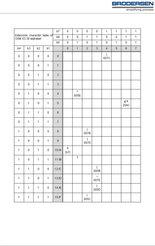
Figure 1.2: Extension character table of GSM 03.38 alphabet
1)This code value is reserved for the extension to another extension table. On receipt of this code, a receiving entity shall display a space until another extension table is defined.
2)This code represents the EURO currency symbol. The code value is the one used for the character 'e'. Therefore a receiving entity which is incapable of displaying the EURO currency symbol will display the character 'e' instead.
3)This code is defined as a Page Break character and may be used for example in compressed CBS messages. Any mobile which does not understand the 7 bit default alphabet table extension mechanism will treat this character as Line Feed.
MC55_ATC_V04.00 |
Page 22 of 475 |
3/17/06 |
Confidential / Released |
|
|

In the event that an MS receives a code where a symbol is not represented in Figure 1.2, Extension character table of GSM 03.38 alphabet the MS shall display the character shown in the main default 7 bit alphabet table (see Figure 1.1, Main character table of GSM 03.38 alphabet).
1.5.2UCS2 and GSM data coding and conversion for SMS text mode
This section provides basic information on how to handle input and output character conversion for SMS text mode and Remote-SAT if internal (TA) and external (TE) character representation differ, i.e. if the Data Coding Scheme and the TE character use different coding.
1.5.2.1Implementing output of SIM data to Terminal (direction TA to TE)
Used character set |
DCS = 7 bit |
DCS = 8 bit |
DCS = 16 bit |
|
GSM |
Data |
UCS2 |
GSM |
Case 1 |
Case 2 |
Case 3 |
|
GSM (1:1) |
8 bit to IRA (1:2) |
UCS2 to IRA (2:4) |
UCS2 |
Case 4 |
Case 5 |
Case 6 |
|
GSM to IRA (1:4) |
8 bit to IRA (1:4) |
UCS2 to IRA (2:4) |
Note: The ratio of SIM bytes to output bytes is given in parentheses.
Case 1
Every GSM character is sent to the TE as it is (8-bit value with highest bit set to zero). Example: 47'H, 53'H, 4D'H → 47'H, 53'H, 4D'H, displayed as "GSM"
Case 2
Every data byte is sent to the TE as 2 IRA characters each representing a halfbyte.
Example: B8'H (184 decimal) → 42'H, 38'H, displayed as "B8"
Case 3
Every 16-bit UCS2 value is sent to the TE as 4 IRA characters.
Example: C4xA7'H (50343 decimal) → 43'H, 34'H, 41'H, 37'H, displayed as "C4A7"
Problem: An odd number of bytes leads to an error because there are always two bytes needed for each USC2 character
Case 4
Every GSM character is sent to the TE as 4 IRA characters to show UCS2 in text mode. Example: 41'H ("A") → 30'H, 30'H, 34'H, 31'H, displayed as "0041"
Case 5
Every data byte is sent to the TE as IRA representation of UCS2 (similar to case 4). Example: B2'H → 30'H, 30'H, 42'H, 32'H, displayed as "00B2"
Case 6
Every 16-bit value is sent to the TE as IRA representation of it. It is assumed that number of bytes is even. Example: C3x46'H → 43'H, 33'H, 34'H, 36'H, displayed as "C346"
MC55_ATC_V04.00 |
Page 23 of 475 |
3/17/06 |
Confidential / Released |
|
|

1.5.2.2Implementing input of Terminal data to SIM (direction TE to TA)
Used character set |
DCS = 7 bit |
DCS = 8 bit |
DCS = 16 bit |
|
GSM |
Data |
UCS2 |
GSM |
Case 1 |
Case 2 |
Case 3 |
|
GSM (1:1) |
IRA to 8 bit (2:1) |
IRA to 16 bit (4:2) |
UCS2 |
Case 4 |
Case 5 |
Case 6 |
|
UCS2 to GSM (4:1) |
UCS2 to 8 bit (4:1) |
UCS2 to 16 bit (4:2) |
Note: The ratio between the number of input characters and bytes stored on the SIM is given in parentheses.
Case 1
Every character is sent from TE to TA as GSM character (or ASCII with standard terminal emulation, e.g. Hyperterminal).
Character value must be in range from 0 to 127 because of 7-bit GSM alphabet.
To reach maximum SMS text length of 160 characters in 140 bytes space characters will be compressed on SIM. This must be set using the parameter <dcs> of AT+CSMP (add 64).
Example: "ABCDEFGH" typed is sent and stored uncompressed as → 4142434445464748'H (stored compressed as 41E19058341E91'H)
Case 2
Every data byte is sent as 2 IRA characters.
Maximum text length is 280 IRA characters which will be converted into 140 bytes SMS binary user data Example: "C8" typed is sent as 43'H, 38'H → stored as C8'H
Case 3
Every 16-bit value is sent as 4 IRA characters.
Maximum text length is 280 IRA characters which will be convertedinto 70 UCS2 characters (16-bit each) Number of IRA characters must be a multiple of four because always 4 half bytes are needed for a 16-bit value Example: "D2C8" typed is sent as 44'H, 32'H, 43'H, 38'H → stored as D2C8'H
Case 4
Every GSM character is sent as 4 IRA characters representing one UCS2 character. Example: To store text "ABC" using UCS2 character set you have to type "004100420043".
This is sent as 30'H,30'H,34'H,31'H, 30'H,30'H,34'H,32'H, 30'H,30'H,34'H,33'H → detected as IRA representation of 3 UCS2 characters, converted to GSM character set and stored as 41'H, 42'H, 43'H.
Maximum input is 640 IRA characters repesenting 160 UCS2 characters when compression is active. These are converted to 160 GSM 7-bit characters.
Without compression only 140 GSM characters can be stored which are put in as 560 IRA characters. Values of UCS2 characters must be smaller than 80'H (128 decimal) to be valid GSM characters. Number of IRA characters must be a multiple of four. Problems:
•"41" → Error, there are four IRA characters (two bytes) needed
•"0000" → Error, not an UCS2 character
•"4142" → Error, value of UCS2 character > 7F'H
•"008B" → Error, value of UCS2 character > 7F'H
This affects the maximum input length of a string)
Case 5
Every UCS2 character is sent as 4 IRA characters and is converted into two 8-bit values. This means that the first two characters have to be '00'.
Example: UCS2 character 009F'H typed as "009F" is sent as 30'H,30'H,39'H,46'H → converted into 8-bit value 9F'H.
Maximum number of UCS2 characters is 140 which are represented by 560 IRA characters. Number of IRA characters must be a multiple of four.
Case 6
Every UCS2 character is sent as 4 IRA characters each and is converted into a 16-bit value again. Example: UCS2 character 9F3A'H typed as "9F3A" is sent as 39'H,46'H,33'H,41'H → converted into 9F3A'H.
Maximum number of UCS2 characters is 70 which are represented by 280 IRA characters. Number of IRA characters must be a multiple of four.
Invalid UCS2 values must be prevented.
MC55_ATC_V04.00 |
Page 24 of 475 |
3/17/06 |
Confidential / Released |
|
|

1.6Serial Interface Flow Control
Flow control is essential to prevent loss of data or avoid errors when, in a data or fax call, the sending device is transferring data faster than the receiving side is ready to accept. When the receiving buffer reaches its capacity, the receiving device should be capable to cause the sending device to pause until it catches up.
There are basically two approaches to regulate data flow: Software flow control and hardware flow control. The High Watermark of the input/output buffer should be set to approximately 60% of the total buffer size. The Low Watermark is recommended to be about 30%. The data flow should be stopped when the capacity rises close to the High Watermark and resumed when it drops below the Low Watermark. The time required to cause stop and go results in a hysteresis between the High and Low Watermarks.
During Multiplex mode (AT+CMUX) it is recommended to use hardware flow control.
1.6.1Software Flow Control (XON/OFF Handshake)
Software flow control sends different characters to stop (XOFF, decimal 19) and resume (XON, decimal 17) data flow. The only advantage of software flow control is that three wires would be sufficient on the serial interface.
1.6.2Hardware Flow Control (RTS/CTS Handshake)
Hardware flow control sets or resets the RTS/CTS wires. This approach is faster and more reliable, and therefore, the better choice. When the High Watermark is reached, CTS is set inactive until the transfer from the buffer has completed. When the Low Watermark is passed, CTS goes active again.
To achieve smooth data flow, ensure that the RTS/CTS lines are present on your application platform. The application should include options to enable RTS/CTS handshake with the GSM engine. This needs to be done with the AT command AT\Q3 - it is not sufficient to set RTS/CTS handshake in the used Terminal program only.
The default setting of the GSM engine is AT\Q0 (no flow control) which must be altered to AT\Q3 (RTS/CTS hardware handshake on). The setting is stored volatile and must be restored each time after the GSM engine was switched off.
AT\Q has no read command. To verify the current setting of AT\Q, simply check the settings of the active profile with AT&V.
Often, fax programs run an intialization procedure when started up. The intialization commonly includes enabling RTS/CTS hardware handshake, eliminating the need to set AT\Q3 once again. However, before setting up a CSD call, you are advised to check that RTS/CTS handshake is set.
RTS/CTS hardware handshake must also be set if you want to take advantage of the CYCLIC SLEEP modes. For further details refer to AT+CFUN.
Note: After deactivating the RTS line, the ME may still send up to 264 bytes (worst case). This can be easily handled if the buffer of the host application is sufficiently sized, and if a hysteresis is implemented regarding its Rx buffer. For host applications that are required to handle a large amount of data at high speed, a total buffer capacity of 512 bytes is recommended.
MC55_ATC_V04.00 |
Page 25 of 475 |
3/17/06 |
Confidential / Released |
|
|

1.7Unsolicited Result Code Presentation
URC stands for Unsolicited Result Code and is a report message issued by the ME without being requested by the TE, i.e. a URC is issued automatically when a certain event occurs. Hence, a URC is not issued as part of the response related to an executed AT command.
Typical events leading to URCs are incoming calls ("RING"), waiting calls, received short messages, changes in temperature, network registration etc.
A list of all URCs can be found in Section 20.7, Summary of Unsolicited Result Codes (URC).
To announce a pending URC transmission the ME will do the following:
•The ME activates its RING line (logic "1") for 1 second, i.e. the RING line changes to the physical "Low" level. This allows the TE to stay in power saving mode until an ME related event requests service.
If several URCs occur coincidently or in quick succession each URC triggers the RING line independently, although the line will not be deactivated between each URC. As a result, the RING line may stay low for more than 1 second.
If an incoming call is answered within less than 1 second (with ATA or if autoanswering is set to ATS0=1) than the RING line will be deactivated earlier.
The "^SHUTDOWN" URC will not activate the RING line.
•If the AT command interface is busy a "BREAK" will be sent immediately but the URC will not be issued until the line is free. This may happen if the URC is pending in the following cases:
-During the processing of an AT command (i.e. the time after the TE echoes back the first character "A" of an AT command just sent by itself until the ME responds with "OK" or "ERROR").
-During a data call.
Please note that AT command settings may be necessary to enable in-band signaling, e.g. refer to AT+CMER or AT+CNMI.
It is strongly recommended to use the multiplex mode to map logical communication channels onto the serial line of the MC55, for details refer to [5] and AT command AT+CMUX. Doing so it is possible to use one channel to still process URCs while having a data call active on another.
For most of these messages, the ME needs to be configured whether or not to send a URC. Depending on the AT command, the URC presentation mode can be saved to the user defined profile (see AT&W), or needs to be activated every time you reboot the ME. Several URCs are not user definable, such as "^SYSSTART", "^SYSSTART <text>", "^SHUTDOWN" and the Fax Class 2 URCs listed in Section 12.1, FAX parameters.
If autobauding is enabled (as factory default mode or set with AT+IPR=0), URCs generated after restart will be output with 57600 bps until the ME has detected the current bit rate. The URCs "^SYSSTART", "^SYSSTART <text>", however, are not presented at all. For details please refer to Section 4.7.1, Autobauding. To avoid problems we recommend to configure a fixed bit rate rather than using autobauding.
1.7.1Communication between Customer Application and MC55
Leaving hardware flow control unconsidered the Customer Application (TE) is coupled with the MC55 (ME) via a receive and a transmit line.
Since both lines are driven by independent devices collisions may (and will) happen, i.e. while the TE issues an AT command the MC55 starts sending an URC. This will probably lead to the TE's misinterpretation of the URC being part of the AT command's response.
To avoid this conflict the following measures must be taken:
•If an AT command is finished (with "OK" or "ERROR") the TE shall always wait at least 100 milliseconds before sending the next one.
This gives the MC55 the opportunity to transmit pending URCs and get necessary service.
Note that some AT commands may require more delay after "OK" or "ERROR" response, refer to the following command specifications for details.
•The TE shall communicate with the MC55 using activated echo (ATE1), i.e. the MC55 echoes characters received from the TE.
Hence, when the TE receives the echo of the first character "A" of the AT command just sent by itself it has control both over the receive and the transmit paths.
MC55_ATC_V04.00 |
Page 26 of 475 |
3/17/06 |
Confidential / Released |
|
|

1.8Common PCN Handset Specification (CPHS)
The ME provides features to implement a device following the prerequisites of the Common PCN Handset Specification (CPHS) Phase 2.
CPHS Feature |
Description/Remarks |
AT command |
Alternate Line Service |
Using two phone numbers with one SIM card. |
AT^SALS |
Voice Message Waiting |
Indicate the receipt of a short message coded as Voice Mes- |
AT^SIND, |
Indication |
sage Waiting Indicator as defined by the CPHS Phase 2 |
AT+CMER, indicators |
|
standard. |
"vmwait1" and |
|
|
"vmwait2" |
Operator (Service pro- |
Read specific Elementary Files (6F14h, 6F18h) from SIM. |
AT+CRSM |
vider) name from SIM |
|
|
Network and Service Pro- |
Lock/Unlock an ME to specific HPLMN and service provider. |
AT+CLCK, |
vider Lock |
|
(AT+CPIN) |
Call Forwarding |
Get and set diverted call status. Access specific Elementary |
AT+CCFC, AT+CRSM |
|
File (6F13h) from SIM. |
|
Customer Service Profile |
Setting services and their menu entries depending on cus- |
AT+CRSM |
(CSP) |
tomer profiles. |
|
Information numbers |
Hierarchically structured service numbers phonebook on |
AT+CRSM |
|
SIM according to CPHS 4.2 (mandatory). |
|
MC55_ATC_V04.00 |
Page 27 of 475 |
3/17/06 |
Confidential / Released |
|
|

1.9Errors and Messages
The command result codes "+CME ERROR: <err>" and "+CMS ERROR: <err>" indicate errors related to mobile equipment or network functionality.
The format of <err> can be either numeric or verbose and is selectable via AT+CMEE.
A result error code terminates the execution of the command and prevents the execution of all remaining commands that may follow on the same command line. If so, neither "ERROR" nor "OK" result codes are returned for these commands. A 30 seconds timeout will deliver "ERROR" when the input of a command is not complete.
Using the wrong command syntax may result in errors: For example, using the execute command syntax although the command has no execute format, causes "ERROR" to be returned. Likewise, using the write command syntax although the command has no write format causes "+CME ERROR: <err>" to be returned.
See also:
•Section 2.11.1, CME/CMS Error Code Overview
•Section 2.5.1, Verbose and numeric result codes
•Section 3.4, AT+CEER
MC55_ATC_V04.00 |
Page 28 of 475 |
3/17/06 |
Confidential / Released |
|
|

2.Configuration Commands
The AT Commands described in this chapter allow the external application to determine the MC55's behaviour under various conditions.
2.1 AT&F Set all current parameters to manufacturer defaults
AT&F sets all current parameters to the manufacturer defined profile. All defined GPRS contexts which are not activated or not online will be undefined (see AT+CGDCONT).
Syntax
Exec Command
AT&F[<value>]
Response(s)
OK
|
Reference(s) |
|
|
|
PIN |
ASC0 |
ASC1 |
MUX1 |
MUX2 |
MUX3 |
Charge |
Last |
|
|
|
|
|
|
|
|
|
|
|
|
|
|
|
|
V.250 |
|
|
|
! |
% |
% |
% |
% |
% |
! |
! ! |
|
|
|
|
|
|
|
|
|
|
|
|
|
|
|
Parameter Description
<value>(num)
[0] Set all TA parameters to manufacturer defaults
Notes
•List of parameters reset to manufacturer default can be found in Section 20.6, Factory Default Settings Restorable with AT&F.
•In addition to the default profile, you can store an individual one with AT&W. To alternate between the two profiles enter either ATZ (loads user profile) or AT&F (restores factory profile).
•Every ongoing or incoming call will be terminated.
MC55_ATC_V04.00 |
Page 29 of 475 |
3/17/06 |
Confidential / Released |
|
|

2.2AT&V Display current configuration
AT&V returns the current parameter setting. The configuration varies depending on whether or not PIN authentication has been done and whether or not Multiplex mode is enabled (see AT+CMUX).
Syntax
Exec Command
AT&V[<value>]
Response(s)
ACTIVE PROFILE:
... (see Section 2.2.1, AT&V responses)
OK
|
Reference(s) |
|
|
|
PIN |
ASC0 |
ASC1 |
MUX1 |
MUX2 |
MUX3 |
Charge |
Last |
|
|
|
|
|
|
|
|
|
|
|
|
|
|
|
|
V.250 |
|
|
|
! |
% |
§ |
% |
§ |
§ |
! |
! ! |
|
|
|
|
|
|
|
|
|
|
|
|
|
|
|
Parameter Description
<value>(num)
[0] Profile number
Notes
•The parameters of AT^SMGO can only be displayed after the SMS data from the SIM have been read successfully for the first time. Reading starts after successful SIM authentication has been performed, and may take up to 30 seconds depending on the SIM used. While the read process is in progress, an attempt to read the parameter will result in empty values.
•The parameter of AT+CSDH will only be displayed in SMS PDU mode, see AT+CMGF.
MC55_ATC_V04.00 |
Page 30 of 475 |
3/17/06 |
Confidential / Released |
|
|
Loading...