


21-115532-001
Installation / Operation / Maintenance
Instructions
JFR Distribution
Step Voltage Regulator
21-115532-001 PR4018-06
SUPERCEDES
21-115532-001
PR4018-05
October 08


TABLE OF CONTENTS
Page
INTRODUCTION
Inspection for Damage in Shipment................... 2
Storage Prior To Installation............................. 2
Physical Considerations ...................................3
Line Terminals and Connections.......................3
Electrical Considerations .................................. 3
Installation Diagrams........................................4
Protective Measures ........................................5
Control Connections ........................................ 5
Connection Diagrams
Straight Design................................................6
Inverted Design................................................7
Series Transformers Design ............................. 8
Placing the Regulator in Service
Before Connecting ...........................................9
Connecting ......................................................9
Switching On-Line ............................................ 9
Checking Regulator Operation..........................9
Removing the Regulator From Service .............10
Maintenance
General Instructions ........................................11
Operational Checks.........................................11
Periodic Inspection..........................................12
Page
Special Features
Polarized Disconnect Switch
and Hinged Control Panel ......................................... 13
Remote Mounting of Control Equipment..................... 13
Vari-AMP
TM
Position Indicator................................... 13
Operation at Less Than Rated Voltage.........................14
Forced Air Cooling ................................................... 15
Subbase Assembly .................................................. 15
Parts List
Major Components................................................... 16
Position Indicator................................................... 17
Type TLG Dial Switch ............................................. 18
Type TLG Quick Break Mechanism ........................... 19
Type TLF Dial Switch ............................................... 20
Type TLF Quick Break Mechanism............................21
Bypass Arresters..................................................... 22
Bushings.................................................................23
For Emergency Service Call :
1-877-742-3309
Siemens Energy, Inc.
THESE INSTRUCTIONS DO NOT PURPORT TO COVER ALL DETAILS OR VARIATIONS IN EQUIPMENT, NOR TO PROVIDE FOR EVERY
POSSIBLE CONTINGENCY TO BE MET IN CONNECTION WITH INSTALLATION, OPERATION OR MAlNTENANCE. SHOULD FURTHER INFOR-
MATION BE DESIRED OR PROBLEMS ARISE WHICH ARE N OT COVERE D SUF ICIENT LY FOR T HE PURCHASER ’S PURPOSES , THE MATTER
SHOULD BE REFERRED TO YOUR SIEMENS ENERGY, INC. REPRESENTATIVE.
THE CONTENTS OF THIS INSTRUCTION MANUAL SHALL NOT BEC OME PART OF OR MODIFY ANY PRIOR OR EXISTING AGREEMENT,
COMMITMENT OR RELATIONSHIP. THE SALES CONTRACT CONTAINS THE ENTIRE OBLIGATION OF SIEMENS ENERGY, INC. THE
WARRANTY CONTAINED IN THE CONTRACT BETWEEN THE PARTIES IS THE SOLE W ARRANTY OF SIEMENS ENERGY, INC. ANY
STATEMENTS CONTAINED HEREIN DO NOT CREATE NEW WARRANTIES OR MODIFY THE EXISTING WARRANTY.

INTRODUCTION
Page 1
Type JFR single-phase step-voltage regulators are designed
to give dependable service and to make installation, operation
and maintenance as simple as possible.
Technology advances, especially in the realm of the control
apparatus, make it efficient to provide a separate instruction
manual for the Accu/Stat
TM
control provided with this JFR
Regulator. For specific control information, refer to the
Accu/Stat
TM
control manual included with the regulator.
QUALIFIED PERSON
FOR THE PURPOSE OF THIS MANUAL AND PRODUCT
LABELS, A QUALIFIED PERSON IS ONE WHO IS FAMILIAR
WITH THE INSTALLATION, CONSTRUCTION AND OPERA-
TION OF THE EQUIPMENT, AND THE HAZARDS INVOLVED.
IN ADDITION, HE HAS THE FOLLOWING QUALIFICATIONS:
(a) Is trained and authorized to de-energize, clear, ground and
tag circuits and equipment in accordance with established
safety practices.
(b) Is trained in the proper care and use of protective
equipment such as rubber gloves, hard hat, safety glasses
or face shields, flash clothing, etc., in accordance with
established safety practices.
(c) Is trained in rendering first aid.
Distinctive signal words (DANGER, WARNING, CAUTION) are
used in this instruction book to indicate degrees of hazard
that may be encountered by the user. For the purpose of this
manual and product labels these signal words are defined
below.
DANGER Indicates an imminently hazardous situation
which, if not avoided, will result in death or
serious injury
WARNING Indicates a potentially hazardous situation,
which, if not avoided, could result in death or
serious injury.
CAUTION Indicates a potentially hazardous situation
which, if not avoided, may result in minor or
moderate injury.
Hazardous Voltag e. Death or serious injury from
electrical shock, burns will result from misuse.
To prevent:
Do not service or touch until you have de-energized
high voltage, grounded all terminals and turned off
control voltage. Grounding terminals with line to
ground capacitors may produce a small arc.
Only qualified personnel should work on or around
this equipment after becoming thoroughly familiar
with all warnings, safety notices, instructions and
maintenance procedures contained herein.
The successful and safe oper ation of this
equipment is dependent upon proper handling,
installation, operation and maintenance.

INTRODUCTION
Page 2
INSPECTION FOR STORAGE PRIOR TO
DAMAGE IN SHIPMENT INSTALLATION
Check each item with the shipping manifest immediately
upon receipt of the regulator. Make a thorough visual in-
spection of the regulator. Check for evidence of damage
attributable to mishandling in shipment. Should any short-
age or damage be found, notify the local agent of the ca rrier
making the delivery and make appropriate notation on the
freight bill. Any damage or shortage that is not noted on the
freight bill becomes the recipients responsibility. A claim
should be made immediately with the carrier. Please also
notify your Siemens representative as soon as possible.
Assure that the control compartment enclosure is tightly
closed, and regulator tank is sealed.
INTRODUCTION
Page 3
PHYSICAL CONSIDERATIONS
• Handling. Type JFR regulators are designed to be lifted
either by a forklift at the base or by use of lifting hooks
on the side of each tank. Each JFR regulator is provided
with either 2 or 4 lifting hooks on the side of each tank.
The number of hooks has been established to provide a
margin of safety. Use all supplied lifting hooks when
lifting.
• Location. Type JFR regulators are designed for outdoor
installation. Any regulator may be platform or pedestal
mounted. Regulators provided with hanger brackets are
suitable for pole mounting. When the regulator is to be
installed in a substation on a pedestal it is recom-
mended that a minimum elevation to the live connection
be established, as required by applicable codes.
Elevation. When the regulator will be used at an elevation
above 1000 meters (3300 feet) the kVA rating must be de-
rated per ANSI C57.15 to assure operating temperature
limits are not exceeded.
LINE TERMINALS AND
CONNECTIONS
Type JFR voltage regulators are routinely equipped with line
bushing terminals per the following criteria.
Nameplate Line Current
Rating
Conductor Size Range
or Threaded Stud Size
50A to 300A #2 to 477 MCM
301A to 668A #2 to 800 MCM
669A to 1200A 1.125- 12 UNF-2A
1201 A to 2000A 1.500- 12 UNF-2A
Clamp type terminals for use through 668 ampere are
capable of accepting an aluminum or copper conductor.
Tank grounding provision consists of a 0.5-13NC tapped
hole in a steel pad for regulators rated to 300 amperes.
Above 300 ampere ratings, a stainless steel pad with two
0.5-13NC tapped holes is provided.
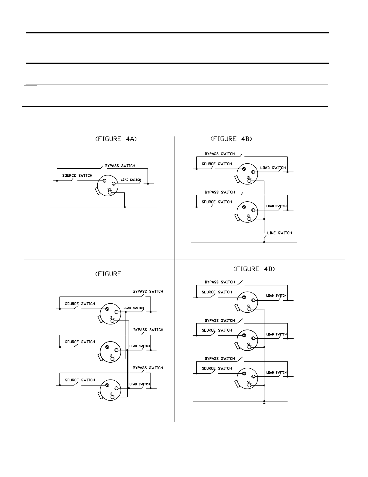
ELECTRICAL CONSIDERATIONS
Type JFR regulators are commonly installed using any of
four electrical configurations.
• One regulator in single-phase application. (Figure 4A)
• Three regulators in wye on a grounded-neutral three-
phase system. (Figure 4D)
• Two regulators in open delta on a three-phase
ungrounded system. (Figure 4B)
• Three regulators in closed delta on a three-phase
ungrounded system. (Figure 4C)
Each of the four alternatives, when complete with switching
provisions, will take the electrical configuration as shown
on the next page.
The descriptions 'S', 'L', and 'SL' are embossed into th e cove r
for user convenience at time of installation.
Improper use of lifting provisions can cause death,
serious injury, or equipment damage.
To prevent:
Do not use cover lifting eyes to lift complete unit.
Cover lifting eyes are for untanking only.
WARNING
Hazardous voltage present at the line terminals of the
bushings on the cover of the regulator.
Will cause serious injury or death.
To prevent:
De-energize the regulator before servicing.
INTRODUCTION
INSTALLATION DIAGRAMS
Connection of two single phase JFR regulators in open
delta on a three phase, ungrounded line.
Connection of one single phase JFR regulator on single
phase line.
Connection of three JFR regulators in closed
delta on three phase, ungrounded system.
Connection of three single phase JFR regulators in
wye on a three phase, grounded neutral system.
Open Delta
Closed Delta
Wye Connected
Single Phase
4C)
Page 4
INTRODUCTION
Page 5
PROTECTIVE MEASURES
Bypass Arrester. All JFR regulators are equipped with a
properly sized arrester , connected externally between the 'S'
and 'L' line terminals. The arrester is provided to protect the
series winding of the regulator from line surges. By itself, the
bypass arrester does not provide lightning protection for the
regulator.
Lightning Protection. The number of lightning arresters used
will be a discretionary decision on the part of the user,
considering such factors as isokeraunic level and degree of
risk of damage to be accepted. The minimum recommended
lightning protection consists of a properly sized arrester
between the 'S' or 'L' bushing and ground on a single phase
or a wye connected system. A delta connection system
requires the use of two arresters to accomplish minimum
protection levels. Additional protection can be obtained with
the use of arresters at both the 'S' and 'L' terminals in single
phase or wye systems and on all three terminals on a delta
system.
For best results, install lightning arresters on the mounting
lugs adjacent to the bushings near the top of the tank. The
lugs are 0.5 - 13NC located on 2.5 inch centers. Ground the
arrester(s) and the regulator tank solidly to the same ground
connection. Be careful to keep the ground lead connections
as short as possible.
Thru Fault. Type JFR regulators are rated under condition of
thru-faults per ANSI C57.15.
The user is advised to provide for additional source imped-
ance, bus sectionalizing or other means of limiting the avail-
able thru-fault current if these criteria are exceeded at the
installation.
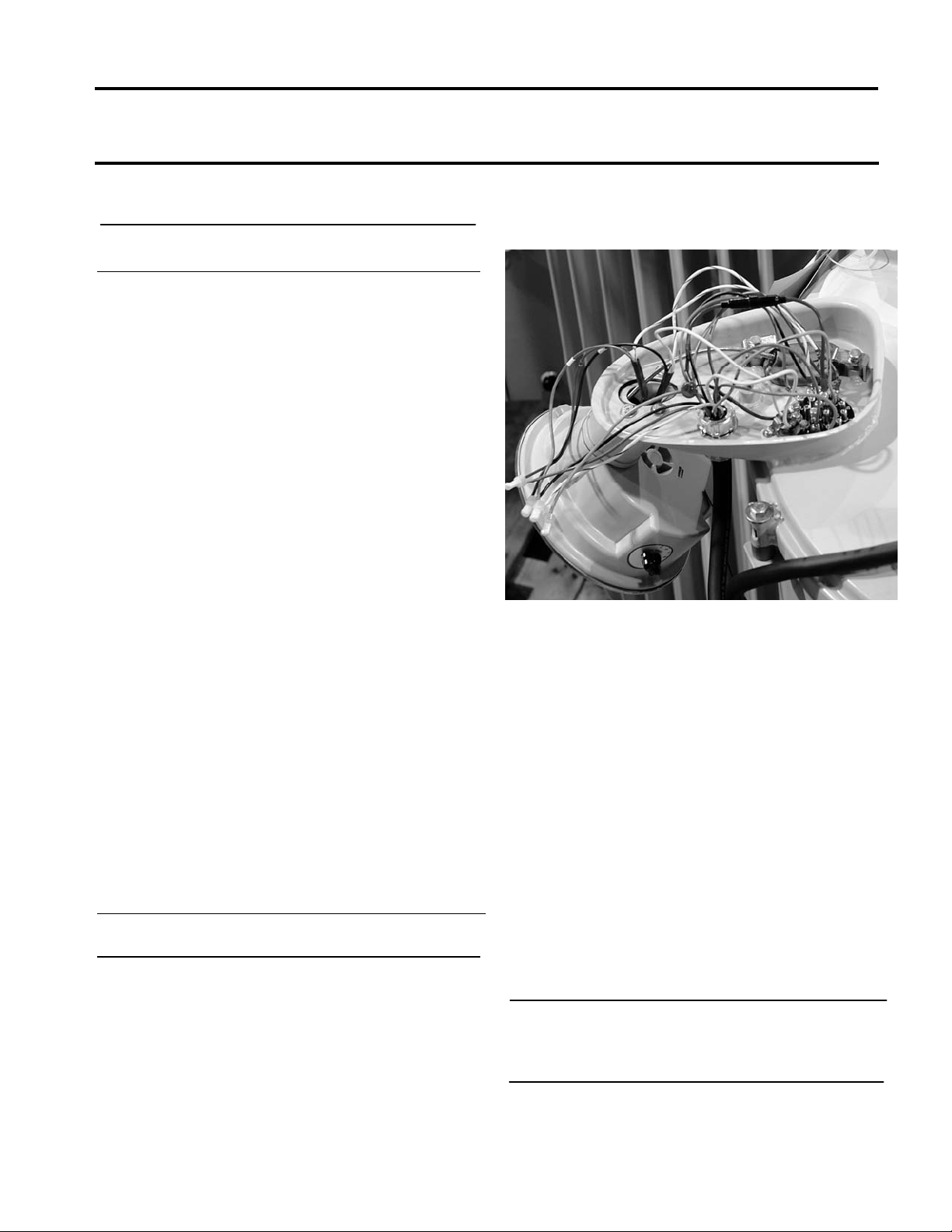
CONTROL CONNECTIONS
Many regulators can be used at several different nominal
system voltages. It is therefore necessary to assure that the
regulator is properly connected at the 19 pin upper terminal
block for the system voltage on which the particular regul ator
will be used.
Figure 5A
For this purpose, it is necessary to use the nameplate
drawing and control diagram found in the control enclosure.
1. Refer to the Nameplate. The P2 column indicates the
correct connection for lead P2 based on the system
voltage. Using the applicable control diagram, the
terminal designation of the nameplate can be cross
referenced to the proper terminal on the 19-pin terminal
block.
2. Depending on the regulator, there may be a second
nameplate column indicating that lead U2 should also be
connected. If so, the U2 column indicates the correct
connection for lead U2 based on the system voltage
Using the applicable control diagram, the “U” terminal
designation of the nameplate can be cross referenced to
the proper terminal on the 19-pin term i na l b lock.
3. For regulator equipped with fans for forced-air cooling,
another set of connections will be shown.
NOTE Matters specifically relating to the Accu/Stat
TM
control used in conjunction with the regulator are
not included in this manual. Refer to the
appropriate control instruction manual.
 Loading...