


Field Panel Web Server
User Guide
125-3584T |
Building Technologies |

Table of Contents
How to Use This Manual ................................................................................................... |
8 |
Related Documents ............................................................................................................. |
8 |
Symbols Used in this Manual .............................................................................................. |
8 |
Manual Conventions ............................................................................................................ |
8 |
Contact Us ........................................................................................................................... |
9 |
Chapter 1 - Introduction to Field Panel Web Server .................................................... |
10 |
||
Applications ....................................................................................................................... |
10 |
||
Chapter 2 - Field Panel Web Server System Administration....................................... |
13 |
||
Chapter Overview .............................................................................................................. |
13 |
||
Prerequisites and Browser Requirements for Field Panel Web Server ............................ |
13 |
||
|
Verifying that Adobe Flash has been Installed................................................... |
14 |
|
Prerequisites for FINlite Graphics Tool.............................................................................. |
14 |
||
Enabling or Disabling Web Server..................................................................................... |
14 |
||
Loading the User Interface ................................................................................................ |
16 |
||
Performance and Limitations............................................................................................. |
17 |
||
|
Tips to Improve Performance of Field Panel Web Server.................................. |
18 |
|
System Security................................................................................................................. |
19 |
||
Language Support ............................................................................................................. |
20 |
||
Chapter 3 - User Interface Navigation Overview .......................................................... |
21 |
||
Welcome Page/Logon ....................................................................................................... |
21 |
||
|
Configuring the Welcome Page Graphic............................................................ |
22 |
|
User Interface after Logon................................................................................................. |
22 |
||
|
Status Bar User Interface................................................................................... |
23 |
|
|
Navigation Pane User Interface ......................................................................... |
23 |
|
|
Application Area User Interface ......................................................................... |
27 |
|
|
Device/Points Navigation Tree........................................................................... |
28 |
|
Chapter 4 - Status Bar..................................................................................................... |
30 |
||
Status Bar Counts and Reports......................................................................................... |
30 |
||
|
Running an Alarm Report................................................................................... |
30 |
|
|
Acknowledging an Alarm.................................................................................... |
30 |
|
Setup |
31 |
|
|
Logoff |
32 |
|
|
Chapter 5 - Point Commander........................................................................................ |
34 |
||
Chapter Overview .............................................................................................................. |
34 |
||
Point Commander Application Overview ........................................................................... |
34 |
||
|
User Interface Description for the Point Commander Application...................... |
35 |
|
|
Tips for Using the Point Commander Application .............................................. |
39 |
|
Using the Point Commander Application........................................................................... |
39 |
||
|
|
|
3 |
Siemens Industry, Inc. |
|
|
125-3584T |

|
Commanding Point Values................................................................................. |
39 |
|
|
Disabling and Re-enabling a Point (Out-of-Service) .......................................... |
40 |
|
|
Priority Arrays ..................................................................................................... |
41 |
|
Chapter 6 - Graphics View .............................................................................................. |
43 |
||
Chapter Overview .............................................................................................................. |
43 |
||
Tips for Using the Graphics View ...................................................................................... |
43 |
||
Using the Graphics View ................................................................................................... |
43 |
||
|
Opening a Graphics View Tab ........................................................................... |
43 |
|
|
Graphics Features.............................................................................................. |
43 |
|
|
Graphics File Types............................................................................................ |
44 |
|
|
Graphics File Navigation .................................................................................... |
44 |
|
Chapter 7 - Point Log Report.......................................................................................... |
46 |
||
Chapter Overview .............................................................................................................. |
46 |
||
Point Log Report Application Overview ............................................................................. |
46 |
||
|
User Interface Description for the Point Log Report Application........................ |
46 |
|
Using the Point Log Report Application............................................................................. |
47 |
||
|
Running a Point Log Report ............................................................................... |
47 |
|
Chapter 8 - Trend View.................................................................................................... |
49 |
||
Chapter Overview .............................................................................................................. |
49 |
||
Trend View Overview......................................................................................................... |
49 |
||
|
Tips for Using the Trend View Application ......................................................... |
49 |
|
Using the Trend View......................................................................................................... |
49 |
||
|
Viewing Trend Data of a Single Trended Point .................................................. |
49 |
|
|
Viewing Trend Data of Multiple Trended Points................................................. |
51 |
|
|
Printing a Trend Graph....................................................................................... |
52 |
|
|
Customizing a Trend Graph ............................................................................... |
53 |
|
Chapter 9 - Schedule View.............................................................................................. |
55 |
||
Chapter Overview .............................................................................................................. |
55 |
||
Scheduler Application Overview ........................................................................................ |
55 |
||
|
User Interface Description for the Scheduler Application................................... |
55 |
|
|
Tips for Using the Scheduler Application ........................................................... |
56 |
|
Using the Scheduler Application........................................................................................ |
56 |
||
Chapter 10 - Create/Edit .................................................................................................. |
58 |
||
Common Editor Fields and Buttons ................................................................................... |
58 |
||
Trend |
60 |
|
|
|
Section Overview................................................................................................ |
60 |
|
|
Trend Application Overview ............................................................................... |
60 |
|
|
Using the Trend Editor Application..................................................................... |
64 |
|
Point |
67 |
|
|
|
Section Overview................................................................................................ |
67 |
|
|
Point Editor Application Overview ...................................................................... |
68 |
|
|
Using the Point Editor Application ...................................................................... |
69 |
|
4 |
|
|
|
Siemens Industry, Inc. |
|
|
125-3584T |

Schedule/Command/Calendar .......................................................................................... |
74 |
||
|
Section Overview ............................................................................................... |
74 |
|
|
Schedule/Command/Calendar Object Editors Overview |
...................................74 |
|
|
Using the Schedule/Command/Calendar Object Editors |
...................................77 |
|
Event Enrollment ............................................................................................................... |
93 |
||
|
Section Overview ............................................................................................... |
93 |
|
|
Event Enrollment Overview................................................................................ |
93 |
|
|
Using the Event Enrollment Editor ..................................................................... |
95 |
|
Notification Class ............................................................................................................... |
99 |
||
|
Section Overview ............................................................................................... |
99 |
|
|
Notification Class Editor Overview ................................................................... |
100 |
|
|
Using the Notification Class Editor................................................................... |
102 |
|
Remote Notification ......................................................................................................... |
105 |
||
|
SMTP Configuration ......................................................................................... |
106 |
|
|
Remote Recipient List ...................................................................................... |
108 |
|
FLN |
112 |
|
|
|
Section Overview ............................................................................................. |
112 |
|
|
FLN Device Editor Overview ............................................................................ |
112 |
|
|
Using the FLN Device Editor............................................................................ |
114 |
|
TEC Init |
117 |
|
|
|
Section Overview ............................................................................................. |
118 |
|
|
TEC Initial Value Editor Overview .................................................................... |
118 |
|
|
Using the TEC Initial Value Editor.................................................................... |
119 |
|
PPCL |
121 |
|
|
|
Section Overview ............................................................................................. |
121 |
|
|
PPCL Editor Overview...................................................................................... |
121 |
|
|
Using the PPCL Editor ..................................................................................... |
124 |
|
Users |
127 |
|
|
|
User Interface Description for the User Account Editor ................................... |
127 |
|
|
Using the User Account Editor ......................................................................... |
131 |
|
Change User Password................................................................................................... |
134 |
||
Change Panel Time ......................................................................................................... |
135 |
||
Chapter 11 - FINlite Graphics Tool............................................................................... |
137 |
||
Chapter Overview ............................................................................................................ |
137 |
||
FINlite Graphics Tool Overview....................................................................................... |
137 |
||
|
User Interface Description for the FINlite Graphics Tool ................................. |
138 |
|
|
Tips for Using the FINlite Graphics Tool .......................................................... |
145 |
|
Using the FINlite Graphics Tool....................................................................................... |
146 |
||
|
Launching the FINlite Graphics Tool................................................................ |
146 |
|
|
Logging in to the Controller .............................................................................. |
147 |
|
|
Creating Graphics ............................................................................................ |
147 |
|
|
Editing the Graphics Animation........................................................................ |
151 |
|
|
Saving and Publishing the Graphics File ......................................................... |
152 |
|
|
|
|
5 |
Siemens Industry, Inc. |
|
|
125-3584T |

Creating Device Templates .............................................................................. |
153 |
Backing Up Graphics........................................................................................ |
155 |
Deleting Graphics Files .................................................................................... |
156 |
Updating the FINlite User Guide ...................................................................... |
158 |
Chapter 12 - Field Panel Features for Field Panel Web Server ................................. |
160 |
Field Panel File System Operations ................................................................................ |
160 |
Basic File System Operation Commands......................................................... |
160 |
Rename a File .................................................................................................. |
162 |
Delete a File ..................................................................................................... |
163 |
Move a File ....................................................................................................... |
164 |
Copy a File ....................................................................................................... |
164 |
Remove a Directory.......................................................................................... |
166 |
Backing up and Restoring Databases ............................................................................. |
168 |
Enabling Auto Save.......................................................................................... |
169 |
Available Memory Diagnostic Point ................................................................................. |
170 |
Chapter 13 - Troubleshooting....................................................................................... |
171 |
Log On Error Messages................................................................................................... |
172 |
Install, Upgrade, and Connection Errors.......................................................................... |
173 |
Graphics Issues ............................................................................................................... |
175 |
Other Issues..................................................................................................................... |
176 |
6 |
|
Siemens Industry, Inc. |
125-3584T |

Copyright Notice 
Copyright Notice
Notice
Document information is subject to change without notice by Siemens Industry, Inc. Companies, names, and various data used in examples are fictitious unless otherwise noted. No part of this document may be reproduced or transmitted in any form or by any means, electronic or mechanical, for any purpose, without the express written permission of Siemens Industry, Inc.
All software described in this document is furnished under a license agreement and may be used or copied only in accordance with license terms.
For further information, contact your nearest Siemens Industry, Inc. representative. Copyright 2012 by Siemens Industry, Inc.
To the Reader
Your feedback is important to us. If you have comments about this manual, please submit them to: SBT_technical.editor.us.sbt@siemens.com
Credits
Staefa and TALON are registered trademarks of Siemens Industry, Inc.
Other product or company names mentioned herein may be the trademarks of their respective owners.
Printed in USA
|
7 |
Siemens Industry, Inc. |
125-3584T |

How to Use This Manual
Related Documents
How to Use This Manual
This manual is for users of TALON® Automation Systems who use Field Panel Web Server to command and monitor their TALON field panels. It is designed to describe the functions and applications of Field Panel Web Server.
To effectively use this manual, you must be familiar with the basic operation of the TALON Building Automation Systems and a Web browser.
Related Documents
In addition to this User Guide, please review the following Siemens Industry, Inc. documentation:
TALON Controllers User's Manual (588-580)
This manual, along with information about other Siemens Industry, Inc. products, technical training classes, and services, can be obtained from the local Siemens Industry, Inc. representative.
Symbols Used in this Manual
The following table lists the safety symbols used in this manual to draw attention to important information.
Symbol |
Meaning |
Description |
|
|
|
NOTICE |
CAUTION |
Equipment damage may occur if a procedure or instruction is not |
|
|
followed as specified. (For online documentation, the NOTICE displays |
|
|
in white with a blue background.) |
|
|
|
|
CAUTION |
Minor or moderate injury may occur if a procedure or instruction is not |
|
|
followed as specified. |
WARNING |
Personal injury or property damage may occur if a procedure or |
|
instruction is not followed as specified. |
DANGER |
Electric shock, death, or severe property damage may occur if a |
|
procedure or instruction is not followed as specified. |
Manual Conventions
The following table lists conventions to help you use this manual in a quick and efficient manner.
8 |
|
Siemens Industry, Inc. |
125-3584T |

|
|
How to Use This Manual |
|
|
|
Contact Us |
|
|
|
|
|
|
|
|
|
|
Convention |
Examples |
|
|
|
|
|
|
Numbered Lists (1, 2, 3…) indicate a |
1. Turn OFF power to the field panel. |
|
|
procedure with sequential steps. |
2. Turn ON power to the field panel. |
|
|
|
3. Contact the local Siemens Solution Partner, Authorized |
|
|
|
TALON Dealer. |
|
|
|
|
|
|
Actions that should be performed are specified |
Type F for Field panels. |
|
|
in boldface font. |
Click OK to save changes and close the dialog box. |
|
|
|
|
|
|
New terms appearing for the first time are |
The field panel continuously executes a user-defined set |
|
|
italicized. |
of instructions called the control program. |
|
|
|
|
|
|
|
This symbol signifies Notes. Notes provide additional |
|
|
|
information or helpful hints. |
|
|
|
|
|
|
Cross references to other information are |
For more information on creating flowcharts, see |
|
|
indicated with an arrow and the page number, |
Flowcharts [→92]. |
|
|
enclosed in brackets: [→92] |
|
|
|
|
|
|
Contact Us
Your feedback is important to us. If you have comments about this manual, please submit them to SBT_technical.editor.us.sbt@siemens.com
|
9 |
Siemens Industry, Inc. |
125-3584T |

Chapter 1 - Introduction to Field Panel Web Server
Applications
Chapter 1 - Introduction to Field Panel Web Server
The Graphical User Interface software or files can only be loaded into a TC Modular or TC Compact 36 controller. Due to space constraints, the Web Server user interface cannot be loaded into a TC Compact 16 or 24 controller.
Once loaded into a panel on the network, the user interface can be accessed from any compatible Web browser (see the Browser Requirements section). Through the browser, you can access and interact with any BACnet IP-enabled controller in the network that has the FPWeb license enabled, including Compact 16 and Compact 24 controllers.
Siemens FINlite Graphics Tool
The Siemens FINlite Graphics Tool is a graphic utility program which can be used to create, modify, animate, and save graphics files to be used with the Web Server Graphics View.
For more information, see the FINlite Graphics Tool section.
Field Panel Features for Field Panel Web Server
There are several new field panel features which can be used with Field Panel Web Server using the HMI. New basic file system operation features include renaming, moving, deleting, and copying a file. Other new features include Auto Save and Graphics Backup.
Applications
Field Panel Web Server includes all the applications a facility operator needs to easily configure, monitor, and control the TALON® Automation System through a simple Web-based user interface.
In the Siemens FINlite graphics utility program and in the Web Server user interface, limit the total number of tabs that are open simultaneously to six (6). This means that any combination of tabs displaying editors or graphics files should not exceed six tabs.
|
Status Bar Reports |
|
Provides the ability to view reports of various conditions. |
|
Point Editor |
|
Allows you to create, modify, and delete points. |
|
Point Commander |
10 |
|
Siemens Industry, Inc. |
125-3584T |
Chapter 1 - Introduction to Field Panel Web Server
Applications
Shows details for a selected point.
Allows commanding of point values and priorities, and disabling of points.
Provides navigation to the trending application.
Point Log Report
Displays a Point Log Report for the selected points.
Generates a printer-ready format of the Point Log Report.
Event Enrollment Editor
Allows you to create, modify, and delete Event Enrollment objects.
Notification Class Editor
Allows you to create, modify, and delete Notification Class objects.
Remote Recipient List Editor
Allows you to add, modify, and delete Remote Recipient addresses.
SMTP Configuration Editor
Allows you to configure the settings required by the SMTP E-Mail server in order to use Remote Notification.
Graphics
Allows you to display/view the graphics that have been created and published to the panel using the Siemens FINlite graphics utility program.
Trend Editor
Allows you to create, modify, and delete Trend Log objects
Trending
Displays Trend data in graphical or report format.
Allows the ability to view Trend Log Object data or dynamic trend data by polling point objects.
Generates a printer-ready format of the Trend Graph.
|
Schedule/Command/Calendar Object Editors |
|
|
Allows you to create, modify, and delete Schedule, Command and Calendar |
|
|
objects. |
|
|
Scheduling |
|
|
11 |
|
Siemens Industry, Inc. |
|
125-3584T |

Chapter 1 - Introduction to Field Panel Web Server
Applications
Displays schedules for a selected date, in several views: Today, Day, Work Week, Week, and Month.
PPCL Editor
Allows you to create, modify and delete Powers Process Control Language (PPCL) programs.
FLN Device Editor
Allows you to create, modify, and delete FLN Devices.
TEC Initial Value Editor
Allows you to set and modify TEC initial values.
User Account Editor
Allows you to create, modify, and delete user accounts.
Change User Password
Allows you to modify passwords.
Change Panel Time
Allows you to modify panel time.
12 |
|
Siemens Industry, Inc. |
125-3584T |

Chapter 2 - Field Panel Web Server System Administration
Chapter Overview
Chapter 2 - Field Panel Web Server System
Administration
Chapter Overview
Chapter 2 discusses the following topics:
Prerequisites and Browser Requirements for Field Panel Web Server
Prerequisites for FINlite Graphics Tool
Enabling and Disabling Web Server
Loading the User Interface
Performance and Limitations
System Security
Language Support
Prerequisites and Browser Requirements for Field
Panel Web Server
Prerequisites
Before using the Field Panel Web Server, be sure to verify the following:
The panels being accessed by Field Panel Web Server use Firmware 3.2.2 or later
– Firmware Revision 3.2.2 must be loaded using FLT 3.11 or later
The FPWeb license must be installed and enabled in each controller that the Web Server UI will be accessing
The panels have Web Server enabled via the HMI
The browser requirements below are met
For more information, see the Loading the User Interface and Connecting to Web
Server section, and the TALON Controllers User's Manual (588-580).
Browser Requirements
Internet Explorer (IE) Version 6.0, 7.0, and 8.0, or Firefox 3.0 or later is required for Field Panel Web Server.
NOTE: Field Panel Web Server has been tested with IE 6.0, 7.0, and 8.0, and Firefox 3.0, but any browser that supports Flash Player 10.1 can be used.
Cookies must be enabled. This can be done by selecting Options from the Tools menu in most browsers.
The Adobe Flash Player Plug-in Version 10.1 or later is required. The user interface may prompt you to update if an older version of Adobe Flash Player is installed. If Adobe Flash Player is not installed, the browser may display an empty browser window.
|
13 |
Siemens Industry, Inc. |
125-3584T |

Chapter 2 - Field Panel Web Server System Administration
Prerequisites for FINlite Graphics Tool
Verifying that Adobe Flash has been Installed
Adobe Flash Player Plug-In Version 10.1 or later is required for the Field Panel Web Server.
In Internet Explorer (IE), complete the following steps to determine whether or not the correct version Adobe Flash is installed on your computer:
1.Launch IE.
2.From the Tools menu, click Internet Options.
3.In the Internet Options dialog box, click the Programs tab.
4.Click Manage Add-ons.
5.Scroll down through the list of add-ons and verify that “Shockwave Flash Object” from Adobe Systems, Incorporated has been installed.
In Firefox, complete the following steps to determine whether or not the correct version Adobe Flash is installed on your computer:
1.Launch Firefox.
2.From the Tools menu, click Options.
3.In the Options dialog box, select the General tab, and then click the Manage AddOns button.
4.In the Add-Ons dialog box, click Plugins.
5.Scroll down through the list of add-ons and verify that Shockwave Flash has been installed.
If Adobe Flash has not been installed, or if an upgrade is necessary, it can be downloaded and installed by the administrator of the computer by following the instructions at http://get.adobe.com/flashplayer/.
Prerequisites for FINlite Graphics Tool
Adobe AIR has been installed (be sure to accept upgrades to Adobe AIR).
Siemens FINlite graphics application has been installed.
The Adobe Flash Player Plug-in Version 10.1 or later is required. The user interface may prompt you to update if an older version of Adobe Flash Player is installed. If Adobe Flash Player is not installed, the browser may display an empty browser window.
For more information, see the FINlite Graphics Tool section, the Loading the User
Interface section, and the TALON Controllers User's Manual (588-580).
Enabling or Disabling Web Server
Use these procedures to enable or disable Web Server via the HMI.
14 |
|
Siemens Industry, Inc. |
125-3584T |

Chapter 2 - Field Panel Web Server System Administration
Enabling or Disabling Web Server
Be sure that the FPWeb license is installed on the field panel.
HMI |
S, H, E, W, M (System, Hardware, Ethernet, Webserver, Modify |
|
|
Example
10:13:04 07/30/2010 FRI Logged on successfully Field panel <40091>
User: <high> <High default user account>
>Point, Application, Time, Message, Cancel, System, passWord, Bye? s
>Diagnostics, Users, dSt, Bacnet, Error_msgs, Hardware, Text, Quit? h
>Fieldpanels, Ethernet, nodeNametable, Disks, Reportprinter, Licensemanager, Quit? e
>ipSettings, Bbmd, Telnet, Webserver, Quit? w >Display, Modify, Uiupgrade, Graphicsbackup, Quit? m >Webserver Enabled (Y/N) : y
>Ok to coldstart (Y/N) : y
Use these procedures to check the enabled/disabled status of Web Server.
HMI |
S, H, E, W, D (System, Hardware, Ethernet, Webserver, Display |
|
|
Example
10:13:04 07/30/2010 FRI Logged on successfully Field panel <40091>
User: <high> <High default user account>
>Point, Application, Time, Message, Cancel, System, passWord, Bye? s
>Diagnostics, Users, dSt, Bacnet, Error_msgs, Hardware, Text, Quit? h
>Fieldpanels, Ethernet, nodeNametable, Disks, Reportprinter, Licensemanager, Quit? e
>ipSettings, Bbmd, Telnet, Webserver, Quit? w >Display, Modify, Uiupgrade, Graphicsbackup, Quit? d Webserver Enabled : Enabled
|
15 |
Siemens Industry, Inc. |
125-3584T |

Chapter 2 - Field Panel Web Server System Administration
Loading the User Interface
Loading the User Interface
Be sure that the FPWeb license is enabled for each field panel.
Recommended Method: Loading or Upgrading the User Interface via
Human-Machine Interface (HMI)
To load or upgrade the User Interface file via HMI (recommended method):
Copy the UIUpgrade folder and its contents from Vantage Web site onto the root of a USB memory device (such as a thumb drive). Do not change the folder or file structure.
NOTE: The files within the UIUpgrade folder include wsroot/fpweb.swf as well as language (.mo) files and other support files.
1.Insert the USB memory device into the USB port of the field panel.
NOTE: Due to USB memory device manufacturer, size, and contents, the time to detect the device will vary from several seconds to one or more minutes. You may verify that the device is attached by using the HMI commands S/H/F/F/L to list the available drives on the Field Panel, and confirm that Drive B is listed.
2.Use the HMI Uiupgrade function (System/Hardware/Ethernet/Webserver/Uiupgrade). When prompted, type Y for Yes, and press ENTER.
The User Interface and support files will be copied from the USB memory device in the field panel’s B:\ drive to the field panel’s internal flash drive (IFD) and to the field panel’s A:\ drive.
Alternate Method: Loading or Upgrading the User Interface via File Transfer Protocol (FTP)
There are many user-friendly FTP tools publicly available that can be used for transferring files between your computer and the field panel.
Telnet must be enabled in order to use FTP. Remember to disable Telnet on the field panel when you are done using the Telnet and FTP services. For information on enabling Telnet, see Troubleshooting.
Telnet must be enabled in order to use FTP. Remember to disable Telnet on the field panel when you are done using the Telnet and FTP services. For information on enabling Telnet, see the TALON Controllers User's Manual (588-580).
To load or upgrade the User Interface file via FTP (alternate method; HMI method is recommended):
Use FTP to copy the UIUpgrade folder and its contents from Vantage Web site or your computer to the root of Drive A on the field panel.
After the transfer, the contents of Drive A should look similar to the following folder structure:
Do one of the following:
16 |
|
Siemens Industry, Inc. |
125-3584T |

Chapter 2 - Field Panel Web Server System Administration
Performance and Limitations
Use the HMI “Uiupgrade” function (System/Hardware/Ethernet/Webserver/Uiupgrade)
Use FTP to transfer the uiupgrade.txt file from Vantage Web site or your computer to the root of Drive A on the field panel.
After the upgrade is complete, the UIupgrade folder is automatically removed from
Drive A. No coldstart is necessary.
If a coldstart occurs, all files are preserved in the IFD.
Performance and Limitations
An interface is available via the Human-Machine Interface (HMI) to save files to and restore files from the RAM drive, USB media, or the Field Panel’s internal flash drive (IFD). For more information, see the TALON Controllers User's Manual (588580).
Graphics files can be published from the Siemens FINlite Graphics Tool to the field panel’s RAM (Drive A) or USB (Drive B). For graphics to be preserved across a coldstart, files must be saved on the internal flash drive (IFD) or stored on a USB drive. Any graphics files stored only on the panel’s RAM drive will not be preserved across a coldstart. Files can be saved to the IFD using the Graphics Backup feature in the HMI.
There are 8MB of RAM available on the RAM (Drive A), but it is recommended that 4MB of RAM is kept available for field panel operations. Individual graphic sizes typically range from 300KB to 500KB, depending on background resolution.
Cache refresh time is affected by the number of objects and FLN devices on the panel. Panels with multiple FLN applications will experience longer refresh times.
USB devices must be formatted as FAT. Due to USB memory device manufacturer, size, and contents, the time to detect the device will vary from several seconds to one or more minutes.
The following devices are supported by the installed device drivers. Cruzer, SanDisk, and Kingston brand devices were used during development and testing.
–ADISK USB 1.1 32MB flash disk
–Aigo USB 1.1 64M flash disk
–Crucial 1G flash disk
–FPT-D US5B2H01 18-in-1 USB card reader/writer
–HP 1G flash disk
–IBM Portable Diskette Drive (floppy drive)
–Integral USB 2.0 2GB flash disk
–Kingston DataTraveler 1GB flash disk
–Kingston DataTraveler 100 2GB flash disk
–Kingston DataTraveler 16GB flash disk
–LACIE USB 2.0 40GB mobile hard drive
–Lexar Media JumpDrive Secure USB 2.0 512MB flash disk
–Memorex 2GB flash disk
–NCP XDrivePlus MMC/SD reader
–Newman USB 1.1 64MB flash disk
–PNY Attache USB 1.1 64MB flash disk
|
17 |
Siemens Industry, Inc. |
125-3584T |

Chapter 2 - Field Panel Web Server System Administration
Performance and Limitations
–PNY Attache (U3) 1GB
–PNY Attache 2GB
–PNY Attache 8GB
–PQI MMC/SD reader
–RedLeaf USB 2.0 256MB flash disk
–SanDisk Cruzer USB 2.0 256MB flash disk
–SanDisk Cruzer Micro 2GB flash disk
–SanDisk Cruzer Micro (U3) 2GB flash disk
–SanDisk Cruzer Micro (U3) 4GB flash disk
–SONY MICROVAULT USM256U2 USB 2.0 256MB flash disk
–Transcend JF V30 4GB flash disk
–Edge DiskGO™ 1GB USB Flash Drive Enhanced for ReadyBoost™
–Edge DiskGO™ 2GB USB Flash Drive Enhanced for ReadyBoost™
–Imation 1GB Swivel USB Flash Drive
–Imation 2GB Swivel USB Flash Drive
–Integral 1GB USB Memory Stick
–MARKEM 1GB USB Memory Stick
–Memorex 1GB TravelDrive™ USB Flash Drive
–Memorex 2GB TravelDrive™ USB Flash Drive
–PNY 1GB Attache USB Flash Drive
–SanDisk 2GB Cruzer® Crossfire USB Flash Drive
–SanDisk 512MB Cruzer® Micro USB Flash Drive
–SanDisk 2GB Cruzer® Micro USB Flash Drive
–SanDisk 4GB Cruzer® Micro USB Flash Drive (U3 function not initialized)
–Sony 512MB Micro Vault Tiny USB Flash Drive
–Sony 2GB Micro Vault Tiny USB Flash Drive
–Sony 1GB Micro Vault Classic USB Flash Drive
–Sony 4GB Micro Vault Classic USB Flash Drive
–X Digital Media 1GB Itty Bit USB Flash Drive
–X Digital Media 1GB Poker Chip USB Flash Drive
–X Digital Media 2GB Itty Bit USB Flash Drive
Field Panel Web Server was benchmarked with five (5) users. However, there is no limit to the number of users that can access Field Panel Web Server simultaneously. Certain actions will cause some performance degradation, when performed by multiple users simultaneously (for example: refreshing the cache, running point log reports, opening graphics, etc.).
Field Panel Web Server was benchmarked with ten (10) panels. However, there is no hard limit to the number of panels accessible through Field Panel Web Server. Access time and performance is affected by the number of panels. As the number of panels on the system increases, so will the login and caching time.
Tips to Improve Performance of Field Panel Web Server
18 |
|
Siemens Industry, Inc. |
125-3584T |
Chapter 2 - Field Panel Web Server System Administration
System Security
Allow Browser Caching of Adobe Flash Player
This setting will be particularly helpful once the panel database is stable. This allows the Field Panel Web Server to keep information about the panel database without needing to continuously read it from the panel.
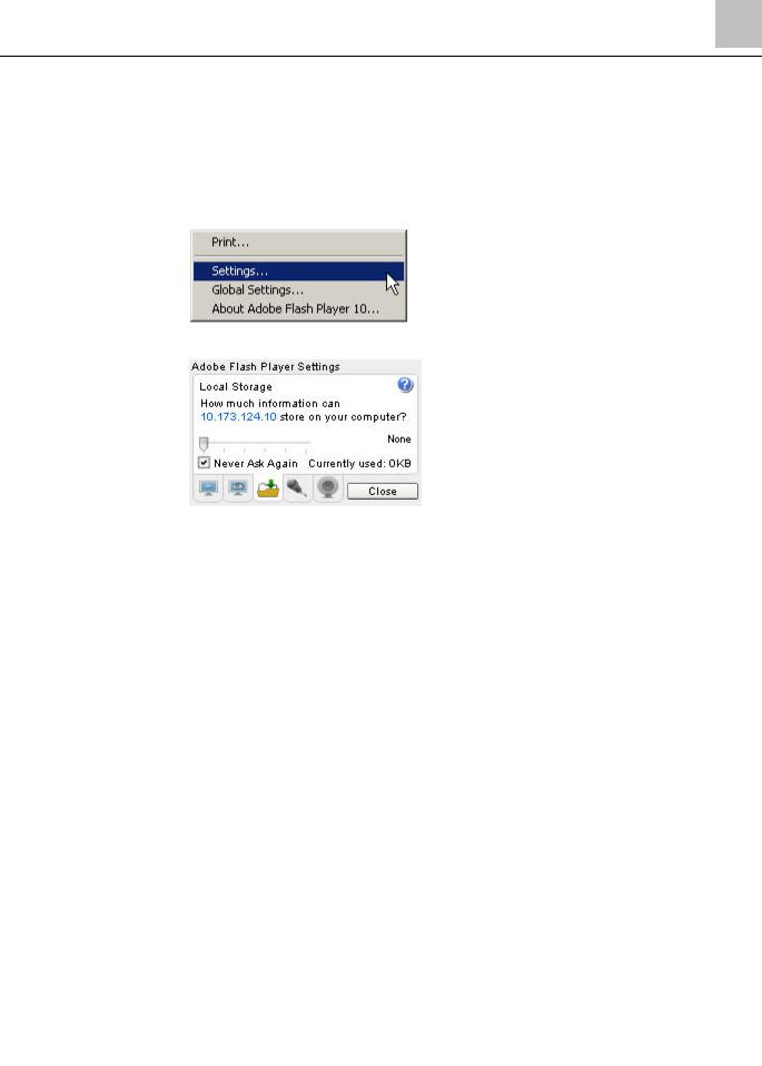
1.Right click while in a browser and accessing the Field Panel Web Server.
2.Click Settings.
3.In the Adobe Flash Player Settings window, open the folder (icon) tab.
4. Choose a local storage setting appropriate to the system being used.
Distribute Points from a Particular Panel among Several Graphics
Loading a graphic with a large number of points from a single panel may degrade the performance of the panel and will cause it to take longer to load and report changes of values (COVs). Particularly, the loading of a graphic with points from a TC Compact 16 or 24, or their associated FLN devices, will occur more slowly, since these panels use a slower processor with lower memory.
To improve performance when loading graphics, distribute the points from the panel among several different graphics files.
Use Device Template Graphics for Viewing FLN Device Points on a Graphic
For information about creating Device Template graphics (also called relativizing), see the Create Device Templates section.
Limit Open Tabs to Six
In the Siemens FINlite graphics utility program and in the Web Server user interface, limit the total number of tabs that are open simultaneously to six (6). This means that any combination of tabs displaying editors or graphics files should not exceed six tabs.
System Security
|
19 |
Siemens Industry, Inc. |
125-3584T |

Chapter 2 - Field Panel Web Server System Administration
Language Support
User access to the Field Panel Web Server is controlled through individual User Accounts. Each User Account has access levels determined by a system administrator, which grant or deny permissions to work with the specific applications and features of the Field Panel Web Server.
User Accounts are password protected. The passwords are encrypted when they are entered by the user at the Web Server User Interface.
When a User Account is created, a password expiration time can be determined by the system administrator. If a user account is created with an expiration date on the password, and if a user attempts to log in to that account three times using an incorrect password, the User Account will be locked, requiring a system administrator to unlock it. A locked User Account can be unlocked through a modification to the User Account by a system administrator.
For more information about access levels and passwords, see the Users section and the TALON Controllers User's Manual (588-580).
Language Support
Dynamic text refers to text that lists object names, descriptors, state text, and other information that can be defined by the user.
Static text refers to text in the user interfaces (HMI, Web Server user interface, and FINlite Graphics Tool), such as menu titles, labels, error messages, and other information that cannot be modified by the user.
Dynamic text support requires appropriate host computer regional settings or the specified language.
Static text support at the Web Server user interface and FINlite Graphics Tool requires downloading the appropriate language (.mo) files in the appropriate place. See the Setup section and the FINlite Graphics Tool sections for information on selecting a static language.
Static and dynamic text support at the HMI requires downloading the appropriate language files during firmware loading via Firmware Loading Tool (FLT), typically English and a second language (French, Chinese, Korean, or Japanese).
See the TALON Controllers User's Manual (588-580) for more information about language support.
Importing a Language File
Additional language (.mo) files can be downloaded from Vantage Web site into the field panel via FTP or a USB memory device. These language files will then become accessible by the user interface for static text display.
20 |
|
Siemens Industry, Inc. |
125-3584T |
Chapter 3 - User Interface Navigation Overview
Welcome Page/Logon
Chapter 3 - User Interface Navigation Overview
Welcome Page/Logon
Begin a Field Panel Web Server session with a Web browser URL request to the panel, using either its IP address or panel name/Fully Qualified Domain Name. The panel will respond with the Web Server Welcome page, which allows you to log on to the system.
If you have problems connecting to the Field Panel Web Server or logging on, see the
Troubleshooting section.
Steps for Logging On
1.Launch a supported Web browser on the computer.
2.Type one of the following into the address field:
-IP address of the field panel
-Field panel node name/Fully Qualified Domain Name
NOTE: The browser must be configured to ignore the proxy settings for the panel names and/or IP addresses. See the Troubleshooting section for more information.
The End User License Agreement page displays.
3.Click Accept.
The Field Panel Web Server Welcome page displays.
NOTE: The graphic that displays on the Welcome page can be customized. See the Settings section.
|
4. Type the user name and password of any ALN user account into the appropriate |
|
|
fields in the log-on window and click Login. |
|
|
If the log-on is successful, a log-on message is sent to all configured alarm printers. |
|
|
The Panel Navigation screen will display, showing a list of panels connected. |
|
|
21 |
|
Siemens Industry, Inc. |
|
125-3584T |

Chapter 3 - User Interface Navigation Overview
User Interface after Logon
Configuring the Welcome Page Graphic
Field Panel Web Server provides a Welcome page image, which can be changed by the user.
To change the image on the Welcome page:
1.Create a custom image file that is 398 × 263 pixels.
2.Name the file login.png.
3.Save the file to a USB drive.
4.There are several ways to save this file in the panel:
5.Using the USB drive as drive B:\ of the panel, copy the login file to A:/wsroot/login.png. Be sure to copy the file to the Internal Flash Drive (IFD:\wsroot\login.png) as well, in order to preserver the file after a panel coldstart. For the HMI command prompts to perform the file copy, see the Field Panel Features for Field Panel Web Server section of this document.
OR
6.Using the USB drive as drive B:\ of the panel, save the file to the WSROOT subdirectory in the UIUpgrade directory, along with the standard contents of the UIUpgrade folder. Perform the UIUpgrade, using the HMI command prompts. The login file will be transferred properly to the correct folder in both the A: and IFD drives. For the HMI command prompts to perform the file copy, see the Field Panel Features for Field Panel Web Server section of this document.
OR
7.Use File Transfer Protocol (FTP) to save the file to WSROOT.
The custom image will display on the Welcome page. If login.png does not exist in the WSROOT directory, the default welcome page image displays.
The Login.png file will be deleted from the A:\ drive after a coldstart of the panel. The file should be copied to the Internal Flash Drive (IFD) so that it will be preserved after a panel coldstart occurs.
User Interface after Logon
Once you are logged in, the Field Panel Web Server user interface is divided into the status bar, the navigation pane, and the application area.
22 |
|
Siemens Industry, Inc. |
125-3584T |
Chapter 3 - User Interface Navigation Overview
User Interface after Logon
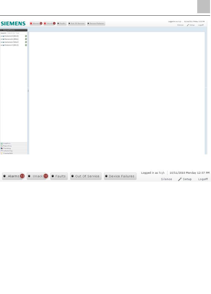
Status Bar User Interface
The Status Bar at the top includes the following features:
Alarms, Unack, Faults, Out Of Service, and Device Failures buttons indicate a count for the number of items in that status. These buttons can be clicked to generate a detailed report for each item in that status. See the Status Bar Counts and Reports section.
The Silence button allows you to stop the Alarms, Unack, Faults, Out Of Service, and Device Failures buttons from flashing until a new item is added to the list.
The Setup button opens a Setup window that allows you to choose colors, text language, font size, and refresh rate of Status Bar buttons. See the Setup section.
The Logoff button allows you to manually log off and return to the Welcome page. See the Logoff section.
User log in information and panel time are displayed.
Navigation Pane User Interface
|
23 |
Siemens Industry, Inc. |
125-3584T |
Chapter 3 - User Interface Navigation Overview
User Interface after Logon
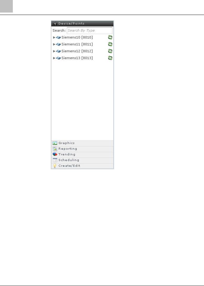
The navigation pane on the left side includes six horizontal main application bars. These main application bars allow you to access the available applications. For descriptions of icons used in the Navigation Pane, see the Device/Points Bar Icons and Messages section. For information about panel accessibility, see the
Accessible/Inaccessible Panels on the ALN section.
Device/Points: This application bar opens by default after successful logon. It provides a tree view of ALN and FLN panels and their associated objects and FLNs. This tree view can be used to start several applications including Point Commander, Trend View, Schedule View, and Graphics View by selecting the appropriate object.
Graphics: This application bar provides a tree view of panels and their associated graphics files. Clicking on a specific graphics file name in this tree view loads that graphic in the Graphics View application.
Reporting: This application bar provides a button for Point Log Reports. Clicking on the Point Log Reports button starts the Point Log Reports application.
Trending: This application bar provides a tree view of panels and their associated Trend Log objects. Clicking on a specific Trend Log object in this tree view launches the trend view application displaying the trend graph for the selected object.
24 |
|
Siemens Industry, Inc. |
125-3584T |
Chapter 3 - User Interface Navigation Overview
User Interface after Logon
Scheduling: This application bar provides a tree view of panels and their associated Schedule, Command, and Calendar objects. Clicking on a specific Schedule object in this tree view launches the scheduler view application displaying the schedule data for the selected object.
NOTE: The Command and Calendar objects in this tree view are inactive. They are not used to start the Schedule View application.
Create/Edit: This application bar provides buttons to start the editing applications. The editing applications include Trend Editor, Point Editor, Schedule Editor, Command Editor, Calendar Editor, Event Enrollment Editor, Notification Class Editor, Remote Recipient List Editor, SMTP Configuration Editor, FLN Editor, TEC Initial Value Editor, PPCL Editor, User Account Editor, Password Reset, and Change Panel Time.
See the specific application sections for more information.
Device/Points Bar Icons and Messages
The Device/Points application bar opens by default after successful logon, or can be opened during any Web Server session by clicking the Device/Points bar in the Navigation Pane. The Device/Points tree view provides status of and information about the ALN panels and their associated objects and FLNs.
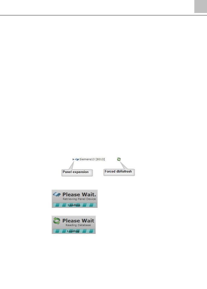
Discovering the Database
When a panel in the Device/Points bar is expanded using the gray arrow to the left of the device name, a database discovery may be triggered.
A database discovery will also be triggered by clicking the green arrows to the right of the device name.
During a database discovery, status messages will display:
Inaccessible Panels on the ALN
The Web Server application can only discover databases for panels on the Automation Level Network (ALN) that are web-enabled, ready, and updated to the current firmware revision.
|
25 |
Siemens Industry, Inc. |
125-3584T |
Chapter 3 - User Interface Navigation Overview
User Interface after Logon
Inaccessible Panels
Panels on the ALN that are not web-enabled will be identified in the Navigation Pane as grayed out. These panels are not accessible in any Web Server editor applications which require panel selection.
Panels on the ALN that are “not ready” will be identified in the Navigation Pane as grayed out. These panels are not accessible in any Web Server editor applications which require panel selection.
Panels on the ALN that are web-enabled and “ready” but not updated to the current firmware revision will be identified in the Navigation Pane with a yellow triangle icon in the Navigation pane next to the panel name. These panels are not accessible in any Web Server editor applications which require panel selection.
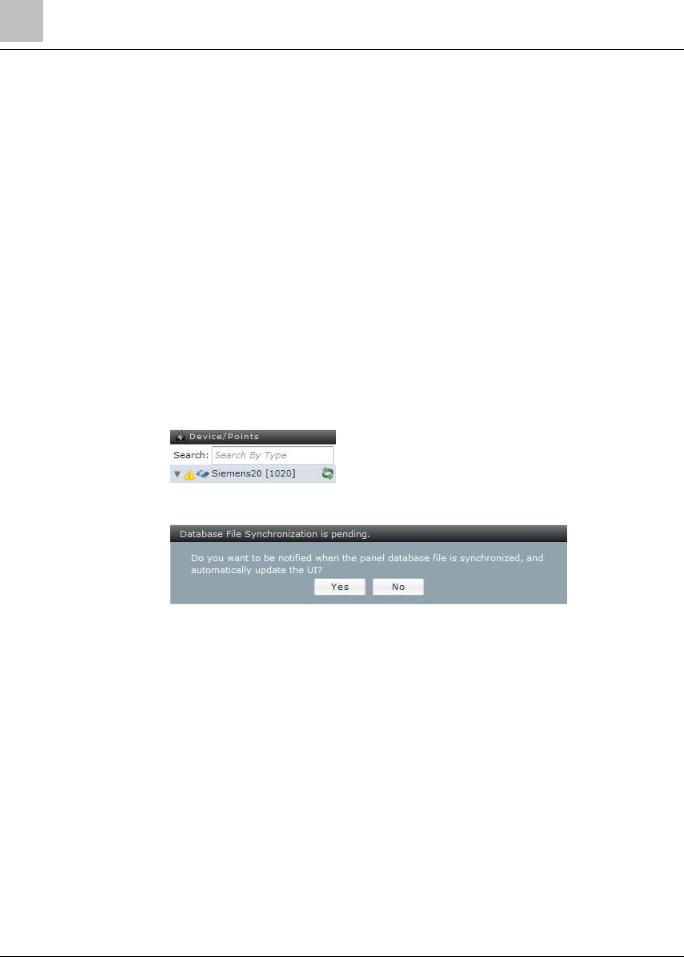
Pending Database File Synchronization
When a panel on the ALN is web-enabled, “ready”, and updated to the current firmware revision, the Web Server application can discover its database, and provide an indication when the database discovery is complete.
When a database discovery has been postponed or was never initiated, a yellow triangle icon will display in the Navigation Pane next to the panel name to indicate a conflict between the panel database file and the user interface database.
When a database discovery is needed, but the panel database file is being synchronized, a message will display:
If this prompt appears while in the FLN Editor, it will only appear once, and the answer will be preserved.
If this prompt appears following a panel expansion arrow selection, the answer will be preserved until the database discovery is complete.
If you click No to this prompt, the yellow triangle icon will display in the Navigation Pane next to the panel name, indicating your request to postpone database discovery.
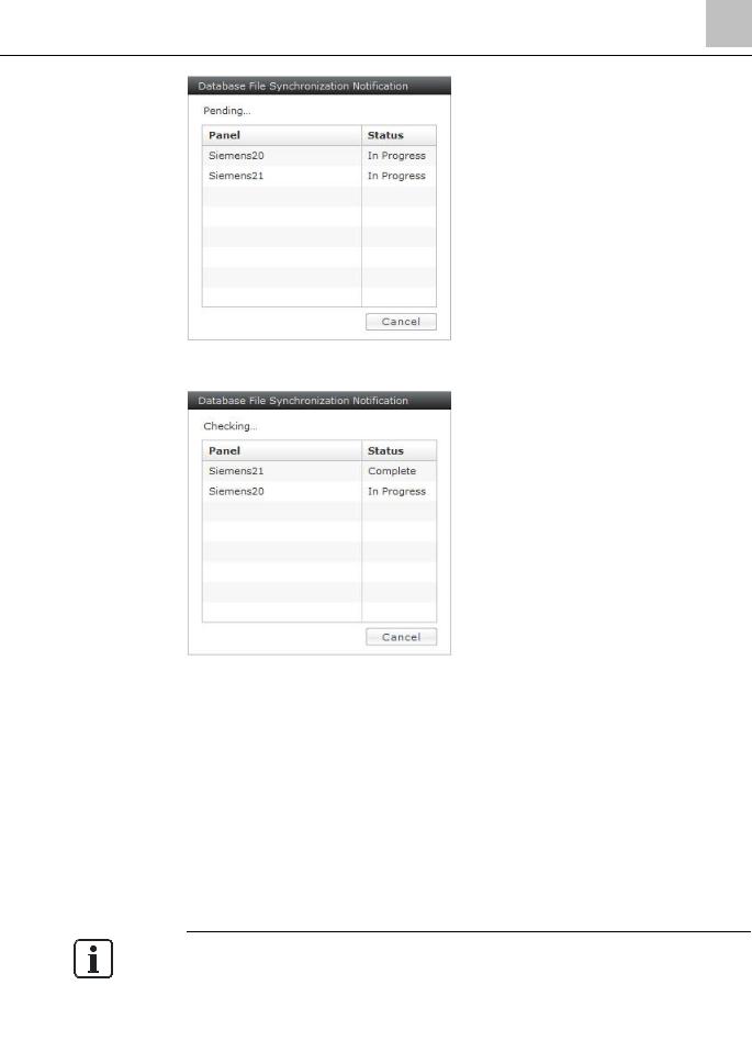
If you click Yes to this prompt, the database will be discovered when the panel’s database file is synchronized. A status table will display indicating the database file synchronization status:
26 |
|
Siemens Industry, Inc. |
125-3584T |
Chapter 3 - User Interface Navigation Overview
User Interface after Logon
When a panel database file has been synchronized, the table will update the panel status:
When all panel database files are synchronized, the status table will disappear, a successful database discovery will occur, and the yellow triangle icon will be removed from the Navigation Pane.
Application Area User Interface
The application area shows the output of the current active application. The information displayed in the application area depends on the application being used. See the specific application section for more information.
When an application is started from the Navigation Pane, either an application window will open on the right side, or an application tab will be open on the right side.
Point Commander and Password Reset open in an application window. All other applications open in tabs.
In the Web Server user interface, limit the total number of tabs that are open simultaneously to six (6). This means that any combination of tabs displaying editors or graphics files should not exceed six tabs.
|
27 |
Siemens Industry, Inc. |
125-3584T |
Chapter 3 - User Interface Navigation Overview
User Interface after Logon
After a successful logon, the Application Area will either be blank or loaded with the “Default.fnl” graphic file loaded in a Graphics View application tab. See the FINlite Graphics Tool section for more information about the default graphic.
Device/Points Navigation Tree
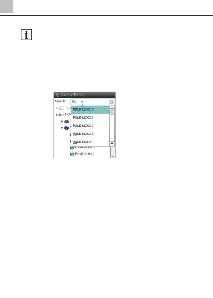
When you click the Device/Points application bar, a navigation tree displays that includes a search box and a list of panels.
Search Box
The Device/Points search box allows searching for points by name. Type any part of the desired point name into the search box and a list of matching point names will display. Click the desired point name to access the point.
Panel List
Panels that are not grayed out are Web Server-enabled panels that are communicating properly.
Panels that are grayed out are either not Web Server-enabled, or are Web Serverenabled panels but are not communicating properly.
1.Hover over a panel name to view panel information. Click the arrow next to a Web Server-enabled panel name to expand and display folders for local points and available applications.
2.Click the arrow to expand the Local option and display the local points, categorized by point type. Clicking a point name will start the Point Commander application.
3.Click the arrow to expand the Trends option to see the Trend Log objects on the panel. Clicking a Trend Log object name will start the Trend View application.
4.Click the arrow to expand the Schedules option to see the Schedule, Command, and Calendar objects on the panel. Clicking a Schedule object name will start the Schedule View application.
NOTE: The Command and Calendar object names are inactive.
28 |
|
Siemens Industry, Inc. |
125-3584T |

Chapter 3 - User Interface Navigation Overview
User Interface after Logon
5.Click the arrow to expand the Graphics options to display the graphic files on the panel.
6.Click the name of a Field Level Network (FLN) option, if available, to display the FLN devices on the panel, which can be further expanded to se the FLN device’s points, categorized by point type. Click the desired point name to access the point in the Point Commander application.
|
29 |
Siemens Industry, Inc. |
125-3584T |

Chapter 4 - Status Bar
Status Bar Counts and Reports
Chapter 4 - Status Bar
Status Bar Counts and Reports
Running an Alarm Report
Alarm details can be viewed in the Alarm report, which is accessible via the Status Bar (see the User Interface Navigation Overview section for more information about the Status Bar and its features). An Alarm report lists the details of both Event Enrollment alarms and Intrinsic Alarms. Alarms can be acknowledged from the Alarm report. Acknowledging the state of an object does not refresh the report. The report must be re-run by clicking the count button to see updated data.
To run an Alarm report:
1.Click the Alarms button in the Status Bar.
An Alarm report will display, listing alarm details.
2.Select the date and time in the Event Time column to see event time and acknowledge time details.
Exporting, Saving, and Printing an Alarm Report
The Alarm report can be exported to the system printer with a preview, or exported as a CSV file, and saved.
To export the Alarm report, click the Export to CSV button at the top right section of the report pane. A dialog box will open. Browse to the desired location to save the CSV (Comma Separated Variable) file.
To print the Alarm report, click the Print button at the top right section of the report pane. A print dialog box will open. Choose the desired printer and click OK.
To close the Alarm report, click the X button to close the Report tab.
Acknowledging an Alarm
To acknowledge an Alarm:
30 |
|
Siemens Industry, Inc. |
125-3584T |
 Loading...