


MULTIMEDIA PROJECTOR
MODEL
XG-MB67X-L
SETUP MANUAL
Connecting Pin Assignments ............................ |
2 |
RS-232C Specifications and Commands .......... |
3 |
Setting up the Projector Network Environment ... |
7 |
1. Connecting the Projector to a Computer ............ |
8 |
2. Setting an IP Address for the Computer ............ |
9 |
3. Setting up a Network Connection for the Projector .. |
11 |
Controlling the Projector via LAN.................... |
13 |
Controlling the Projector Using Internet Explorer |
|
(Version 5.0 or later) ................................... |
13 |
Confirming the Projector Status (Status) ............. |
14 |
Controlling the Projector (Control) ....................... |
14 |
Setting and Adjusting the Projector |
|
(Settings & Adjustments) ............................ |
15 |
Setting the Security (Network – Security) ............ |
15 |
Making General Settings for the Network |
|
(Network – General) .................................. |
16 |
Setting for Sending E-mail when an Error Occurs |
|
(Mail – Originator Settings) ....................... |
16 |
Setting Error Items and Destination Addresses |
|
to which E-mail is to be Sent when an |
|
Error Occurs (Mail – Recipient Settings) ... |
17 |
Setting Error Items and the URL that are to be |
|
Displayed when an Error Occurs |
|
(Service & Support – Access URL) ........... |
17 |
Setting up the Projector Using RS-232C or Telnet .... |
18 |
When Connecting Using RS-232C ....................... |
18 |
When Connecting Using Telnet ............................ |
19 |
SETUP MENU (Main Menu) ................................. |
20 |
ADVANCED SETUP MENU ................................. |
20 |
View Setting Detail List ([V]View All Setting) ....... |
21 |
Set Items ............................................................... |
21 |
Save Settings and Quit ([S]Save & Quit) ............. |
22 |
Quit without Saving Settings ([Q]Quit Unchanged) .. |
22 |
IP Address Setting ([1]IP Address) ...................... |
23 |
Subnet Mask Setting ([2]Subnet Mask) ............... |
23 |
Default Gateway Setting ([3]Default Gateway) .... |
23 |
User Name Setting ([4]User Name) ..................... |
23 |
Password Setting ([5]Password) .......................... |
24 |
RS-232C Baud Rate Setting |
|
([6]RS-232C Baud Rate) ............................ |
24 |
Projector Name Setting ([7]Projector Name) ....... |
24 |
DHCP Client Setting ([8]DHCP Client) ................. |
24 |
Disconnecting All Connections |
|
([D]Disconnect All) ..................................... |
25 |
Entering ADVANCED SETUP MENU |
|
([A]Advanced Setup) .................................. |
25 |
Setting Auto Logout Time |
|
(ADVANCED[1]Auto Logout Time) ............. |
25 |
Data Port Setting (ADVANCED[2]Data Port) ....... |
25 |
Carrying out Network Ping Test |
|
(ADVANCED[5]Network Ping Test) ............ |
26 |
Setting of Accept IP Address (ADVANCED[6]Accept |
|
IP Addr(1) – [8]Accept IP Addr(3)) ................ |
26 |
Accepting All IP Addresses |
|
(ADVANCED[9]Accept All IP Addr) ............ |
26 |
Setting of Search Port |
|
(ADVANCED[0]Search Port) ...................... |
27 |
Return to Default Settings |
|
(ADVANCED[!]Restore Default Setting) ............ |
27 |
Return to Main Menu |
|
(ADVANCED[Q]Return to Main Menu) .............. |
27 |
Resetting the Lamp Timer of the Projector |
|
via LAN ....................................................... |
28 |
Troubleshooting ................................................. |
30 |
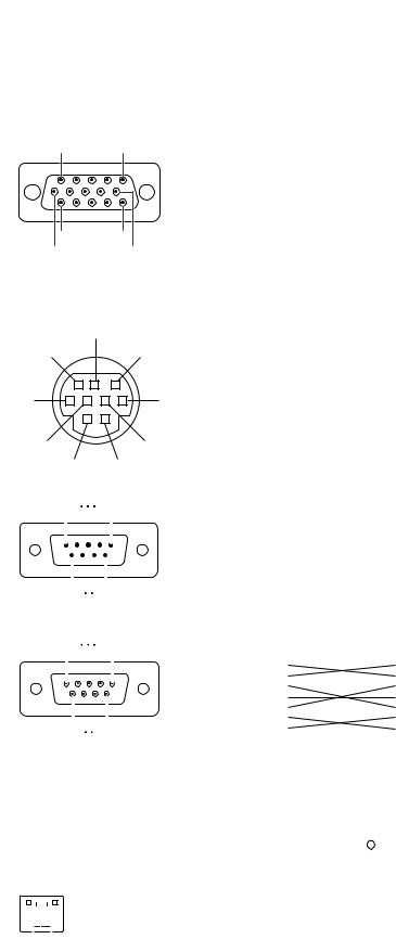
Connecting Pin Assignments
COMPUTER-RGB/COMPONENT INPUT 1, 2 and COMPUTER-RGB/COMPONENT OUTPUT Terminals:
15-pin mini D-sub female connector
11 
 15
15
1 
 5
5
6 
 10
10
COMPUTER-RGB Input/Output |
Component Input/Output |
||
1. |
Video input (red) |
1. |
PR (CR) |
2. |
Video input (green/sync on green) |
2. |
Y |
3. |
Video input (blue) |
3. |
PB (CB) |
4. |
Not connected |
4. |
Not connected |
5. |
Not connected |
5. |
Not connected |
6. |
Earth (red) |
6. |
Earth (PR) |
7. |
Earth (green/sync on green) |
7. |
Earth (Y) |
8. |
Earth (blue) |
8. |
Earth (PB) |
9. |
Not connected |
9. |
Not connected |
10. |
GND |
10. |
Not connected |
11. |
Not connected |
11. |
Not connected |
12. |
Bi-directional data |
12. |
Not connected |
13. |
Horizontal sync signal: TTL level |
13. |
Not connected |
14. |
Vertical sync signal: TTL level |
14. |
Not connected |
15. |
Data clock |
15. |
Not connected |
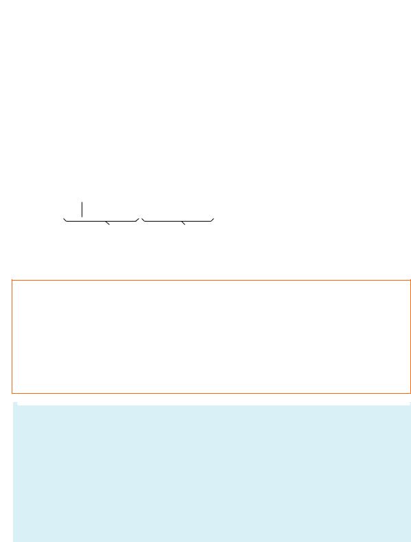
RS-232C Terminal: 9-pin mini DIN female connector
8 |
|
|
|
Pin No. |
Signal |
Name |
I/O |
Reference |
||
|
|
|
|
|
|
1 |
|
|
|
Not connected |
9 |
|
|
7 |
2 |
RD |
Receive Data |
Input |
Connected to internal circuit |
||
|
|
|
|
|
|
3 |
SD |
Send Data |
Output |
Connected to internal circuit |
|
|
|
|
|
|
4 |
|
|
|
Not connected |
|
|
|
|
|
|
5 |
SG |
Signal Ground |
|
Connected to internal circuit |
6 |
|
|
3 |
6 |
|
|
|
Not connected |
||
|
|
7 |
RS |
Request to Send |
|
Connected to CS in internal circuit |
||||
|
|
|
|
|
|
8 |
CS |
Clear to Send |
|
Connected to RS in internal circuit |
|
|
|
|
|
|
9 |
|
|
|
Not connected |
5 |
|
|
4 |
|
|
|
|
|
||
2 |
1 |
|
|
|
|
|
||||
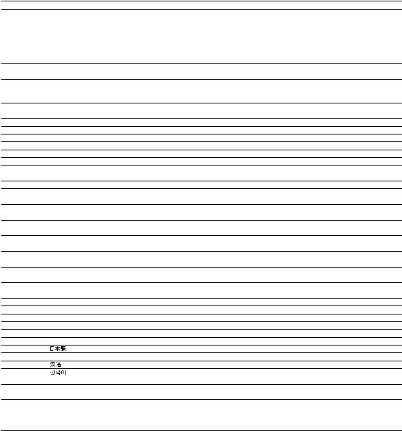
RS-232C Terminal: 9-pin D-sub male connector of the DIN-D-sub RS-232C adaptor |
||||||||||
1 |
|
5 |
Pin No. |
Signal |
Name |
I/O |
Reference |
|||
|
|
|
|
|
|
1 |
|
|
|
Not connected |
|
|
|
|
|
|
|
|
|
||
|
|
|
|
|
|
2 |
RD |
Receive Data |
Input |
Connected to internal circuit |
|
|
|
|
|
|
3 |
SD |
Send Data |
Output |
Connected to internal circuit |
|
|
|
|
|
|
4 |
|
|
|
Not connected |
|
|
|
|
|
|
5 |
SG |
Signal Ground |
|
Connected to internal circuit |
|
|
|
|
|
|
6 |
|
|
|
Not connected |
|
|
|
|
|
|
7 |
RS |
Request to Send |
|
Connected to CS in internal circuit |
|
|
|
|
|
|
8 |
CS |
Clear to Send |
|
Connected to RS in internal circuit |
6 |
9 |
|
|
|||||||
|
9 |
|
|
|
Not connected |
|||||
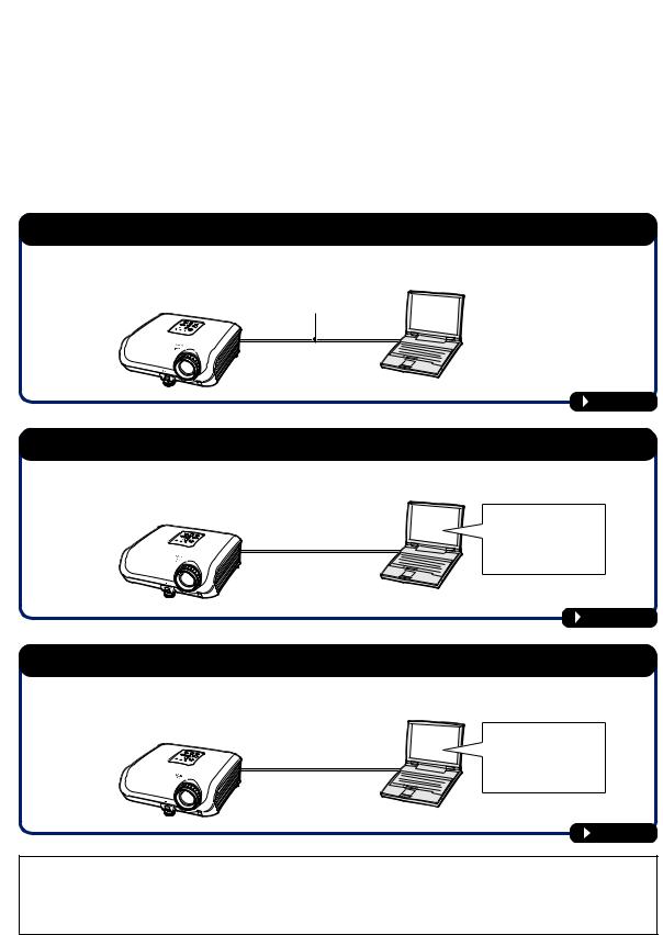
RS-232C Cable recommended connection: 9-pin D-sub female connector |
||||||||||
5 |
|
1 |
Pin No. |
Signal |
Pin No. |
Signal |
|
|||
|
1 |
CD |
1 |
CD |
|
|||||
|
|
|
|
|
|
|
||||
|
|
|
|
|
|
2 |
RD |
2 |
RD |
|
|
|
|
|
|
|
3 |
SD |
3 |
SD |
|
|
|
|
|
|
|
4 |
ER |
4 |
ER |
|
|
|
|
|
|
|
5 |
SG |
5 |
SG |
|
|
|
|
|
|
|
|
||||
|
|
|
|
|
|
6 |
DR |
6 |
DR |
|
|
|
|
|
|
|
7 |
RS |
7 |
RS |
|
9 |
6 |
|
8 |
CS |
8 |
CS |
|
|||
|
|
|
|
|
|
9 |
CI |
9 |
CI |
|
 Note
Note
• Depending on the controlling device used, it may be necessary to connect Pin 4 and Pin 6 on the controlling device (e.g. computer).
Projector |
Computer |
||||||
Pin No. |
|
Pin No. |
|||||
4 |
|
|
|
|
|
4 |
|
5 |
|
|
|
|
|
5 |
|
|
|
|
|
|
|||
6 |
|
|
|
|
|
6 |
|
LAN Terminal : 8-pin RJ-45 modular connector
|
|
|
|
|
|
|
|
|
|
|
|
|
Pin No. |
Signal |
Pin No. |
Signal |
|
|
|
|
|
|
|
|
|
|
|
|
|
1 |
TX+ |
5 |
|
|
|
|
|
|
|
|
|
|
|
|
|
|
2 |
TX– |
6 |
RX– |
|
|
|
|
|
|
|
|
|
|
|
|
|
3 |
RX+ |
7 |
|
|
|
|
|
|
|
|
|
|
|
|
|
|
4 |
|
8 |
|
8...1 |
|
|
||||||||||||||
|
|
|
|
|||||||||||||
 -2
-2
RS-232C Specifications and Commands
Computer control
A computer can be used to control the projector by connecting an RS-232C serial control cable (cross type, commercially available) to the projector. (See page 26 of the projector’s operation manual for connection.)
Communication conditions
Set the serial port settings of the computer to match that of the table.
Signal format: Conforms to RS-232C standard. |
Parity bit: None |
Baud rate*: 9,600 bps / 115,200 bps |
Stop bit: 1 bit |
Data length: 8 bits |
Flow control: None |
*Set the projector’s baud rate to the same rate as used by the computer.
Basic format
Commands from the computer are sent in the following order: command, parameter, and return code. After the projector processes the command from the computer, it sends a response code to the computer.
Command format |
|
|
|
|
|
|
|
|
|
|
|
|
|
|
|
|
|
|
||
|
C1 C2 |
C3 |
C4 |
P1 |
P2 |
P3 |
P4 |
|
|
|
|
|
Return code (0DH) |
|
|
|||||
|
|
|
|
|
|
|
|
|
|
|
|
|
|
|
|
|
|
|
|
|
Response code format |
Command 4-digit |
Parameter 4-digit |
|
|
|
|
||||||||||||||
|
|
|
|
|
|
|
|
|
|
|
|
|
|
|
|
|
|
|||
Normal response |
|
Problem response (communication error or incorrect command) |
||||||||||||||||||
|
|
|
|
|
|
|
|
|
|
|
|
|
|
|
||||||
|
O |
K |
|
|
Return code (0DH) |
|
|
|
E |
R |
R |
|
Return code (0DH) |
|
||||||
|
|
|
|
|
|
|
|
|
|
|
|
|
|
|
|
|
|
|
|
|
 Info
Info
•When controlling the projector using RS-232C commands from a computer, wait for at least 30 seconds after the power has been turned on, and then transmit the commands.
•When more than one code is being sent, send each command only after the response code for the previous command from the projector is verified.
•“POWR????” “TABN _ _ _ 1” “TLPS _ _ _ 1” “TPOW _ _ _ 1” “TLPN _ _ _ 1” “TLTT _ _ _ 1” “TLTL _ _ _ 1”
“TNAM _ _ _ 1” “MNRD _ _ _ 1” “PJN0 _ _ _ 1” When the projector receives a command shown above:
*The on-screen display will not disappear.
*The “Auto Power Off” timer will not be reset.
 Note
Note
•If an underbar (_) appears in the parameter column, enter a space.
•If an asterisk (*) appears in the parameter column, enter a value in the range indicated in brackets under Control Contents.
*1 For setting the projector name, send the commands in the order of PJN1, PJN2 and PJN3. *2 Parameters of CLR Temp settings are as follows.
CLR Temp |
Parameter |
CLR Temp |
Parameter |
5500K |
_0 5 5 |
8500K |
_0 8 5 |
6500K |
_0 6 5 |
9300K |
_0 9 3 |
7500K |
_0 7 5 |
10500K |
_1 0 5 |
 -3
-3

RS-232C Specifications and Commands
Commands
Example: When turning on the projector, make the following setting.
|
|
|
|
Computer |
|
|
|
|
|
|
|
|
|
→ |
|
Projector |
|||||||
|
P |
O |
W |
R |
_ |
_ |
|
|
_ |
|
|
1 |
|
|
|
O |
|
K |
|
|
|
||
|
|
|
|
|
|
|
|
← |
|
|
|
|
|||||||||||
|
|
|
|
|
|
|
|
|
|
|
|
|
|
|
|
|
|
|
|
|
|
|
|
|
|
|
|
|
|
|
|
|
|
|
|
|
|
|
|
|
|
|
|
|
|
|
|
|
|
|
|
|
|
|
|
|
|
|
|
|
|
|
|
|
|
RETURN |
|
|
|
||
|
CONTROL CONTENTS |
|
|
|
COMMAND |
PARAMETER |
|
Power ON |
|
|
|
|
|
|
Standby mode |
||||||||
|
|
|
|
|
|
|
|
|
|
|
|
|
|
|
|
|
|
|
|
|
(or 30-second startup time) |
||
|
|
|
|
|
|
|
|
|
|
|
|
|
|
|
|
|
|
|
|
|
|
||
Power Off |
|
|
|
|
|
P |
O |
W |
R |
_ |
_ |
_ |
0 |
OK or ERR |
|
|
|
|
OK |
||||
Power On |
|
|
|
|
|
P |
O |
W |
R |
_ |
_ |
_ |
1 |
OK |
|
|
|
|
OK or ERR |
||||
Power Status |
|
|
|
|
|
P |
O |
W |
R |
? |
? |
? |
? |
1 |
|
|
|
|
|
0 |
|
||
Projector Condition |
|
|
|
|
|
T |
A |
B |
N |
_ |
_ |
_ |
1 |
0 : Normal, |
|
|
|
|
0 : Normal, |
||||
|
|
|
|
|
|
|
|
|
|
|
|
|
|
|
1 : Temp High, |
|
|
|
|
1 : Temp High, |
|||
|
|
|
|
|
|
|
|
|
|
|
|
|
|
|
8 : Lamp Life 5% or less, |
|
|
|
|
2 : Fan Error, |
|||
|
|
|
|
|
|
|
|
|
|
|
|
|
|
|
16 : Lamp Burnt-out, |
|
|
|
|
4 : Lamp Cover Open, |
|||
|
|
|
|
|
|
|
|
|
|
|
|
|
|
|
32 : Lamp Ignition Failure |
|
|
|
|
8 : Lamp Life 5% or less, |
|||
|
|
|
|
|
|
|
|
|
|
|
|
|
|
|
|
|
|
|
|
|
16 : Lamp Burnt-out, |
||
|
|
|
|
|
|
|
|
|
|
|
|
|
|
|
|
|
|
|
|
|
32 : Lamp Ignition Failure, |
||
|
|
|
|
|
|
|
|
|
|
|
|
|
|
|
|
|
|
|
|
|
64 : Temp Abnormally High |
||
Lamp Status |
|
|
|
|
|
T |
L |
P |
S |
_ |
_ |
_ |
1 |
0 : Off, 1 : On, 2 : Retry, 3 : Waiting, 4 : Lamp Error |
0 : Off, 4 : Lamp Error |
||||||||
Lamp Power Status |
|
|
|
|
|
T |
P |
O |
W |
_ |
_ |
_ |
1 |
1 : On, 2 : Cooling, 3 : Shutting Down |
0 : Standby |
||||||||
Lamp Quantity |
|
|
|
|
|
T |
L |
P |
N |
_ |
_ |
_ |
1 |
1 |
|
|
|
|
|
|
|
|
|
Lamp Usage Time (Hour) |
|
|
|
|
|
T |
L |
T |
T |
_ |
_ |
_ |
1 |
0 – 9999 (Integer) |
|
|
|
|
|
|
|
||
Lamp Life (Percentage) |
|
|
|
|
|
T |
L |
T |
L |
_ |
_ |
_ |
1 |
0% – 100% (Integer) |
|
|
|
|
|
|
|
||
Model Name Check |
|
|
|
|
|
T |
N |
A |
M |
_ |
_ |
_ |
1 |
XGMB67XL |
|
|
|
|
|
|
|
||
Model Name Check |
|
|
|
|
|
M |
N |
R |
D |
_ |
_ |
_ |
1 |
XG-MB67X-L |
|
|
|
|
|
|
|
||
Projector Name Setting 1 |
|
|
|
|
|
P |
J |
N |
1 |
* |
* |
* |
* |
OK or ERR |
|
|
|
|
|
|
|
||
(First four characters) *1 |
|
|
|
|
|
|
|
|
|
|
|
|
|
|
|
|
|
|
|
|
|
|
|
Projector Name Setting 2 |
|
|
|
|
|
P |
J |
N |
2 |
* |
* |
* |
* |
OK or ERR |
|
|
|
|
|
|
|
||
(Middle four characters) *1 |
|
|
|
|
|
|
|
|
|
|
|
|
|
|
|
|
|
|
|
|
|
|
|
Projector Name Setting 3 |
|
|
|
|
|
P |
J |
N |
3 |
* |
* |
* |
* |
OK or ERR |
|
|
|
|
|
|
|
||
(Last four characters) *1 |
|
|
|
|
|
|
|
|
|
|
|
|
|
|
|
|
|
|
|
|
|
|
|
Projector Name Check |
|
|
|
|
|
P |
J |
N |
0 |
_ |
_ |
_ |
1 |
Projector Name |
|
|
|
|
|
|
|
||
INPUT 1 (RGB1) |
|
|
|
|
|
I |
R |
G |
B |
_ |
_ |
_ |
1 |
OK or ERR |
|
|
|
|
ERR |
||||
INPUT 2 (RGB2) |
|
|
|
|
|
I |
R |
G |
B |
_ |
_ |
_ |
2 |
OK or ERR |
|
|
|
|
ERR |
||||
INPUT RGB Check |
|
|
|
|
|
I |
R |
G |
B |
? |
? |
? |
? |
1 : RGB1 (INPUT1), 2 : RGB2 (INPUT2), ERR |
ERR |
||||||||
INPUT 3 (Video1) |
|
|
|
|
|
I |
V |
E |
D |
_ |
_ |
_ |
1 |
OK or ERR |
|
|
|
|
ERR |
||||
INPUT 4 (Video2) |
|
|
|
|
|
I |
V |
E |
D |
_ |
_ |
_ |
2 |
OK or ERR |
|
|
|
|
ERR |
||||
INPUT Video Check |
|
|
|
|
|
I |
V |
E |
D |
? |
? |
? |
? |
1 : Video1 (INPUT3), 2 : Video2 (INPUT4), ERR |
ERR |
||||||||
INPUT Mode Check |
|
|
|
|
|
I |
M |
O |
D |
? |
? |
? |
? |
1 : RGB, 2 : Video |
|
|
|
|
ERR |
||||
INPUT Check |
|
|
|
|
|
I |
C |
H |
K |
? |
? |
? |
? |
1 : INPUT1, 2 : INPUT2, 3 : INPUT3, 4 : INPUT4 |
ERR |
||||||||
INPUT 1 Adjustment Reset |
|
|
|
|
|
R |
A |
R |
E |
_ |
_ |
_ |
1 |
OK or ERR |
|
|
|
|
ERR |
||||
INPUT 2 Adjustment Reset |
|
|
|
|
|
R |
B |
R |
E |
_ |
_ |
_ |
1 |
OK or ERR |
|
|
|
|
ERR |
||||
INPUT 3 Adjustment Reset |
|
|
|
|
|
V |
A |
R |
E |
_ |
_ |
_ |
1 |
OK or ERR |
|
|
|
|
ERR |
||||
INPUT 4 Adjustment Reset |
|
|
|
|
|
V |
B |
R |
E |
_ |
_ |
_ |
1 |
OK or ERR |
|
|
|
|
ERR |
||||
All Reset |
|
|
|
|
|
A |
L |
R |
E |
_ |
_ |
_ |
1 |
OK or ERR |
|
|
|
|
ERR |
||||
Volume (0 – 60) |
|
|
|
|
|
V |
O |
L |
A |
_ |
_ |
* |
* |
OK or ERR |
|
|
|
|
ERR |
||||
Volume up / down ( 10 – 10) |
|
|
|
|
|
V |
O |
U |
D |
_ |
* |
* |
* |
OK or ERR |
|
|
|
|
ERR |
||||
Keystone ( 127 – 127) |
|
|
|
|
|
K |
E |
Y |
S |
_ |
* |
* |
* |
OK or ERR |
|
|
|
|
ERR |
||||
AV Mute Off |
|
|
|
|
|
I |
M |
B |
K |
_ |
_ |
_ |
0 |
OK or ERR |
|
|
|
|
ERR |
||||
AV Mute On |
|
|
|
|
|
I |
M |
B |
K |
_ |
_ |
_ |
1 |
OK or ERR |
|
|
|
|
ERR |
||||
Freeze Off |
|
|
|
|
|
F |
R |
E |
Z |
_ |
_ |
_ |
0 |
OK or ERR |
|
|
|
|
ERR |
||||
Freeze On |
|
|
|
|
|
F |
R |
E |
Z |
_ |
_ |
_ |
1 |
OK or ERR |
|
|
|
|
ERR |
||||
Auto Sync Start |
|
|
|
|
|
A |
D |
J |
S |
_ |
_ |
_ |
1 |
OK or ERR |
|
|
|
|
ERR |
||||
INPUT 1 Resize : Normal |
|
|
|
|
|
R |
A |
S |
R |
_ |
_ |
_ |
1 |
OK or ERR |
|
|
|
|
ERR |
||||
INPUT 1 Resize : Stretch |
|
|
|
|
|
R |
A |
S |
R |
_ |
_ |
_ |
2 |
OK or ERR |
|
|
|
|
ERR |
||||
INPUT 1 Resize : Border |
|
|
|
|
|
R |
A |
S |
R |
_ |
_ |
_ |
6 |
OK or ERR |
|
|
|
|
ERR |
||||
INPUT 2 Resize : Normal |
|
|
|
|
|
R |
B |
S |
R |
_ |
_ |
_ |
1 |
OK or ERR |
|
|
|
|
ERR |
||||
INPUT 2 Resize : Stretch |
|
|
|
|
|
R |
B |
S |
R |
_ |
_ |
_ |
2 |
OK or ERR |
|
|
|
|
ERR |
||||
INPUT 2 Resize : Border |
|
|
|
|
|
R |
B |
S |
R |
_ |
_ |
_ |
6 |
OK or ERR |
|
|
|
|
ERR |
||||
INPUT 3 Resize : Normal |
|
|
|
|
|
R |
A |
S |
V |
_ |
_ |
_ |
1 |
OK or ERR |
|
|
|
|
ERR |
||||
INPUT 3 Resize : Stretch |
|
|
|
|
|
R |
A |
S |
V |
_ |
_ |
_ |
2 |
OK or ERR |
|
|
|
|
ERR |
||||
INPUT 3 Resize : Border |
|
|
|
|
|
R |
A |
S |
V |
_ |
_ |
_ |
3 |
OK or ERR |
|
|
|
|
ERR |
||||
INPUT 4 Resize : Normal |
|
|
|
|
|
R |
B |
S |
V |
_ |
_ |
_ |
1 |
OK or ERR |
|
|
|
|
ERR |
||||
INPUT 4 Resize : Stretch |
|
|
|
|
|
R |
B |
S |
V |
_ |
_ |
_ |
2 |
OK or ERR |
|
|
|
|
ERR |
||||
INPUT 4 Resize : Border |
|
|
|
|
|
R |
B |
S |
V |
_ |
_ |
_ |
3 |
OK or ERR |
|
|
|
|
ERR |
||||
INPUT 1 Picture Mode : Standard |
|
|
|
|
|
R |
A |
P |
S |
_ |
_ |
1 |
0 |
OK or ERR |
|
|
|
|
ERR |
||||
 -4
-4

RS-232C Specifications and Commands
|
|
|
|
|
|
|
|
|
|
|
RETURN |
|
CONTROL CONTENTS |
COMMAND |
PARAMETER |
|
Power ON |
|
Standby mode |
||||||
|
|
|
|
|
|
|
|
|
|
|
(or 30-second startup time) |
|
|
|
|
|
|
|
|
|
|
|
|
|
|
INPUT 1 Picture Mode : Presentation |
R |
A |
P |
S |
_ |
_ |
1 |
1 |
OK or ERR |
|
|
ERR |
INPUT 1 Picture Mode : Movie |
R |
A |
P |
S |
_ |
_ |
1 |
2 |
OK or ERR |
|
|
ERR |
INPUT 1 Picture Mode : Game |
R |
A |
P |
S |
_ |
_ |
1 |
3 |
OK or ERR |
|
|
ERR |
INPUT 1 Picture Mode : sRGB |
R |
A |
P |
S |
_ |
_ |
1 |
4 |
OK or ERR |
|
|
ERR |
INPUT 1 Contrast ( 30 – 30) |
R |
A |
P |
I |
_ |
* |
* |
* |
OK or ERR |
|
|
ERR |
INPUT 1 Bright ( 30 – 30) |
R |
A |
B |
R |
_ |
* |
* |
* |
OK or ERR |
|
|
ERR |
INPUT 1 Color ( 30 – 30) |
R |
A |
C |
O |
_ |
* |
* |
* |
OK or ERR |
|
|
ERR |
INPUT 1 Tint ( 30 – 30) |
R |
A |
T |
I |
_ |
* |
* |
* |
OK or ERR |
|
|
ERR |
INPUT 1 Red ( 30 – 30) |
R |
A |
R |
D |
_ |
* |
* |
* |
OK or ERR |
|
|
ERR |
INPUT 1 Blue ( 30 – 30) |
R |
A |
B |
E |
_ |
* |
* |
* |
OK or ERR |
|
|
ERR |
INPUT 1 Sharp ( 30 – 30) |
R |
A |
S |
H |
_ |
* |
* |
* |
OK or ERR |
|
|
ERR |
INPUT 1 CLR Temp *2 |
R |
A |
C |
T |
_ |
* |
* |
* |
OK or ERR |
|
|
ERR |
INPUT 1 Bright Boost (0 – 2) |
R |
A |
W |
E |
_ |
_ |
_ |
* |
OK or ERR |
|
|
ERR |
INPUT 1 Progressive : 2D |
R |
A |
I |
P |
_ |
_ |
_ |
0 |
OK or ERR |
|
|
ERR |
INPUT 1 Progressive : 3D |
R |
A |
I |
P |
_ |
_ |
_ |
1 |
OK or ERR |
|
|
ERR |
INPUT 1 Progressive : Film Mode |
R |
A |
I |
P |
_ |
_ |
_ |
2 |
OK or ERR |
|
|
ERR |
INPUT 1 Signal Type : Auto |
I |
A |
S |
I |
_ |
_ |
_ |
0 |
OK or ERR |
|
|
ERR |
INPUT 1 Signal Type : RGB |
I |
A |
S |
I |
_ |
_ |
_ |
1 |
OK or ERR |
|
|
ERR |
INPUT 1 Signal Type : Component |
I |
A |
S |
I |
_ |
_ |
_ |
2 |
OK or ERR |
|
|
ERR |
INPUT 2 Picture Mode : Standard |
R |
B |
P |
S |
_ |
_ |
1 |
0 |
OK or ERR |
|
|
ERR |
INPUT 2 Picture Mode : Presentation |
R |
B |
P |
S |
_ |
_ |
1 |
1 |
OK or ERR |
|
|
ERR |
INPUT 2 Picture Mode : Movie |
R |
B |
P |
S |
_ |
_ |
1 |
2 |
OK or ERR |
|
|
ERR |
INPUT 2 Picture Mode : Game |
R |
B |
P |
S |
_ |
_ |
1 |
3 |
OK or ERR |
|
|
ERR |
INPUT 2 Picture Mode : sRGB |
R |
B |
P |
S |
_ |
_ |
1 |
4 |
OK or ERR |
|
|
ERR |
INPUT 2 Contrast ( 30 – 30) |
R |
B |
P |
I |
_ |
* |
* |
* |
OK or ERR |
|
|
ERR |
INPUT 2 Bright ( 30 – 30) |
R |
B |
B |
R |
_ |
* |
* |
* |
OK or ERR |
|
|
ERR |
INPUT 2 Color ( 30 – 30) |
R |
B |
C |
O |
_ |
* |
* |
* |
OK or ERR |
|
|
ERR |
INPUT 2 Tint ( 30 – 30) |
R |
B |
T |
I |
_ |
* |
* |
* |
OK or ERR |
|
|
ERR |
INPUT 2 Red ( 30 – 30) |
R |
B |
R |
D |
_ |
* |
* |
* |
OK or ERR |
|
|
ERR |
INPUT 2 Blue ( 30 – 30) |
R |
B |
B |
E |
_ |
* |
* |
* |
OK or ERR |
|
|
ERR |
INPUT 2 Sharp ( 30 – 30) |
R |
B |
S |
H |
_ |
* |
* |
* |
OK or ERR |
|
|
ERR |
INPUT 2 CLR Temp *2 |
R |
B |
C |
T |
_ |
* |
* |
* |
OK or ERR |
|
|
ERR |
INPUT 2 Bright Boost (0 – 2) |
R |
B |
W |
E |
_ |
_ |
_ |
* |
OK or ERR |
|
|
ERR |
INPUT 2 Progressive : 2D |
R |
B |
I |
P |
_ |
_ |
_ |
0 |
OK or ERR |
|
|
ERR |
INPUT 2 Progressive : 3D |
R |
B |
I |
P |
_ |
_ |
_ |
1 |
OK or ERR |
|
|
ERR |
INPUT 2 Progressive : Film Mode |
R |
B |
I |
P |
_ |
_ |
_ |
2 |
OK or ERR |
|
|
ERR |
INPUT 2 Signal Type : Auto |
I |
B |
S |
I |
_ |
_ |
_ |
0 |
OK or ERR |
|
|
ERR |
INPUT 2 Signal Type : RGB |
I |
B |
S |
I |
_ |
_ |
_ |
1 |
OK or ERR |
|
|
ERR |
INPUT 2 Signal Type : Component |
I |
B |
S |
I |
_ |
_ |
_ |
2 |
OK or ERR |
|
|
ERR |
INPUT 3 Picture Mode : Standard |
V |
A |
P |
S |
_ |
_ |
1 |
0 |
OK or ERR |
|
|
ERR |
INPUT 3 Picture Mode : Presentation |
V |
A |
P |
S |
_ |
_ |
1 |
1 |
OK or ERR |
|
|
ERR |
INPUT 3 Picture Mode : Movie |
V |
A |
P |
S |
_ |
_ |
1 |
2 |
OK or ERR |
|
|
ERR |
INPUT 3 Picture Mode : Game |
V |
A |
P |
S |
_ |
_ |
1 |
3 |
OK or ERR |
|
|
ERR |
INPUT 3 Contrast ( 30 – 30) |
V |
A |
P |
I |
_ |
* |
* |
* |
OK or ERR |
|
|
ERR |
INPUT 3 Bright ( 30 – 30) |
V |
A |
B |
R |
_ |
* |
* |
* |
OK or ERR |
|
|
ERR |
INPUT 3 Color ( 30 – 30) |
V |
A |
C |
O |
_ |
* |
* |
* |
OK or ERR |
|
|
ERR |
INPUT 3 Tint ( 30 – 30) |
V |
A |
T |
I |
_ |
* |
* |
* |
OK or ERR |
|
|
ERR |
INPUT 3 Sharp ( 30 – 30) |
V |
A |
S |
H |
_ |
* |
* |
* |
OK or ERR |
|
|
ERR |
INPUT 3 CLR Temp *2 |
V |
A |
C |
T |
_ |
* |
* |
* |
OK or ERR |
|
|
ERR |
INPUT 3 Bright Boost (0 – 2) |
V |
A |
W |
E |
_ |
_ |
_ |
* |
OK or ERR |
|
|
ERR |
INPUT 3 Progressive : 2D |
V |
A |
I |
P |
_ |
_ |
_ |
0 |
OK or ERR |
|
|
ERR |
INPUT 3 Progressive : 3D |
V |
A |
I |
P |
_ |
_ |
_ |
1 |
OK or ERR |
|
|
ERR |
INPUT 3 Progressive : Film Mode |
V |
A |
I |
P |
_ |
_ |
_ |
2 |
OK or ERR |
|
|
ERR |
INPUT 4 Picture Mode : Standard |
V |
B |
P |
S |
_ |
_ |
1 |
0 |
OK or ERR |
|
|
ERR |
INPUT 4 Picture Mode : Presentation |
V |
B |
P |
S |
_ |
_ |
1 |
1 |
OK or ERR |
|
|
ERR |
INPUT 4 Picture Mode : Movie |
V |
B |
P |
S |
_ |
_ |
1 |
2 |
OK or ERR |
|
|
ERR |
INPUT 4 Picture Mode : Game |
V |
B |
P |
S |
_ |
_ |
1 |
3 |
OK or ERR |
|
|
ERR |
INPUT 4 Contrast ( 30 – 30) |
V |
B |
P |
I |
_ |
* |
* |
* |
OK or ERR |
|
|
ERR |
INPUT 4 Bright ( 30 – 30) |
V |
B |
B |
R |
_ |
* |
* |
* |
OK or ERR |
|
|
ERR |
INPUT 4 Color ( 30 – 30) |
V |
B |
C |
O |
_ |
* |
* |
* |
OK or ERR |
|
|
ERR |
INPUT 4 Tint ( 30 – 30) |
V |
B |
T |
I |
_ |
* |
* |
* |
OK or ERR |
|
|
ERR |
 -5
-5
RS-232C Specifications and Commands
|
|
|
|
|
|
|
|
|
|
RETURN |
|
CONTROL CONTENTS |
COMMAND |
PARAMETER |
Power ON |
|
Standby mode |
||||||
|
|
|
|
|
|
|
|
|
|
(or 30-second startup time) |
|
|
|
|
|
|
|
|
|
|
|
|
|
INPUT 4 Sharp ( 30 – 30) |
V |
B |
S |
H |
_ |
* |
* |
* |
OK or ERR |
|
ERR |
INPUT 4 CLR Temp *2 |
V |
B |
C |
T |
_ |
* |
* |
* |
OK or ERR |
|
ERR |
INPUT 4 Bright Boost (0 – 2) |
V |
B |
W |
E |
_ |
_ |
_ |
* |
OK or ERR |
|
ERR |
INPUT 4 Progressive : 2D |
V |
B |
I |
P |
_ |
_ |
_ |
0 |
OK or ERR |
|
ERR |
INPUT 4 Progressive : 3D |
V |
B |
I |
P |
_ |
_ |
_ |
1 |
OK or ERR |
|
ERR |
INPUT 4 Progressive : Film Mode |
V |
B |
I |
P |
_ |
_ |
_ |
2 |
OK or ERR |
|
ERR |
Clock ( 150 – 150) |
I |
N |
C |
L |
* |
* |
* |
* |
OK or ERR |
|
ERR |
Phase ( 30 – 30) |
I |
N |
P |
H |
_ |
* |
* |
* |
OK or ERR |
|
ERR |
H-Position ( 150 – 150) |
I |
A |
H |
P |
* |
* |
* |
* |
OK or ERR |
|
ERR |
V-Position ( 60 – 60) |
I |
A |
V |
P |
_ |
* |
* |
* |
OK or ERR |
|
ERR |
Fine Sync Adjustment Reset |
I |
A |
R |
E |
_ |
_ |
_ |
1 |
OK or ERR |
|
ERR |
Auto Sync : Off |
A |
A |
D |
J |
_ |
_ |
_ |
0 |
OK or ERR |
|
ERR |
Auto Sync : On |
A |
A |
D |
J |
_ |
_ |
_ |
1 |
OK or ERR |
|
ERR |
Internal Speaker : Off |
A |
S |
P |
K |
_ |
_ |
_ |
0 |
OK or ERR |
|
ERR |
Internal Speaker : On |
A |
S |
P |
K |
_ |
_ |
_ |
1 |
OK or ERR |
|
ERR |
Image Shift ( 96 – 96 ) |
L |
N |
D |
S |
_ |
* |
* |
* |
OK or ERR |
|
ERR |
OSD Display : Off |
I |
M |
D |
I |
_ |
_ |
_ |
0 |
OK or ERR |
|
ERR |
OSD Display : On |
I |
M |
D |
I |
_ |
_ |
_ |
1 |
OK or ERR |
|
ERR |
Video System Selection : AUTO |
M |
E |
S |
Y |
_ |
_ |
_ |
1 |
OK or ERR |
|
ERR |
Video System Selection : PAL |
M |
E |
S |
Y |
_ |
_ |
_ |
2 |
OK or ERR |
|
ERR |
Video System Selection : SECAM |
M |
E |
S |
Y |
_ |
_ |
_ |
3 |
OK or ERR |
|
ERR |
Video System Selection : NTSC4.43 |
M |
E |
S |
Y |
_ |
_ |
_ |
4 |
OK or ERR |
|
ERR |
Video System Selection : NTSC3.58 |
M |
E |
S |
Y |
_ |
_ |
_ |
5 |
OK or ERR |
|
ERR |
Video System Selection : PAL_M |
M |
E |
S |
Y |
_ |
_ |
_ |
6 |
OK or ERR |
|
ERR |
Video System Selection : PAL_N |
M |
E |
S |
Y |
_ |
_ |
_ |
7 |
OK or ERR |
|
ERR |
Video System Selection : PAL-60 |
M |
E |
S |
Y |
_ |
_ |
_ |
8 |
OK or ERR |
|
ERR |
Background Selection : Logo |
I |
M |
B |
G |
_ |
_ |
_ |
1 |
OK or ERR |
|
ERR |
Background Selection : Blue |
I |
M |
B |
G |
_ |
_ |
_ |
3 |
OK or ERR |
|
ERR |
Background Selection : None |
I |
M |
B |
G |
_ |
_ |
_ |
4 |
OK or ERR |
|
ERR |
Lamp Setting : Bright |
T |
H |
M |
D |
_ |
_ |
_ |
0 |
OK or ERR |
|
ERR |
Lamp Setting : Eco Quiet |
T |
H |
M |
D |
_ |
_ |
_ |
1 |
OK or ERR |
|
ERR |
Auto Search : Off |
I |
N |
S |
E |
_ |
_ |
_ |
0 |
OK or ERR |
|
ERR |
Auto Search : On |
I |
N |
S |
E |
_ |
_ |
_ |
1 |
OK or ERR |
|
ERR |
Auto Power Off : Off |
A |
P |
O |
W |
_ |
_ |
_ |
0 |
OK or ERR |
|
ERR |
Auto Power Off : On |
A |
P |
O |
W |
_ |
_ |
_ |
1 |
OK or ERR |
|
ERR |
Auto Keystone : Off |
A |
T |
K |
S |
_ |
_ |
_ |
0 |
OK or ERR |
|
ERR |
Auto Keystone : On |
A |
T |
K |
S |
_ |
_ |
_ |
1 |
OK or ERR |
|
ERR |
PRJ Mode : Reverse Off |
I |
M |
R |
E |
_ |
_ |
_ |
0 |
OK or ERR |
|
ERR |
PRJ Mode : Reverse On |
I |
M |
R |
E |
_ |
_ |
_ |
1 |
OK or ERR |
|
ERR |
PRJ Mode : Invert Off |
I |
M |
I |
N |
_ |
_ |
_ |
0 |
OK or ERR |
|
ERR |
PRJ Mode : Invert On |
I |
M |
I |
N |
_ |
_ |
_ |
1 |
OK or ERR |
|
ERR |
Language Selection : ENGLISH |
M |
E |
L |
A |
_ |
_ |
_ |
1 |
OK or ERR |
|
ERR |
Language Selection : DEUTSCH |
M |
E |
L |
A |
_ |
_ |
_ |
2 |
OK or ERR |
|
ERR |
Language Selection : ESPAÑOL |
M |
E |
L |
A |
_ |
_ |
_ |
3 |
OK or ERR |
|
ERR |
Language Selection : NEDERLANDS |
M |
E |
L |
A |
_ |
_ |
_ |
4 |
OK or ERR |
|
ERR |
Language Selection : FRANÇAIS |
M |
E |
L |
A |
_ |
_ |
_ |
5 |
OK or ERR |
|
ERR |
Language Selection : ITALIANO |
M |
E |
L |
A |
_ |
_ |
_ |
6 |
OK or ERR |
|
ERR |
Language Selection : SVENSKA |
M |
E |
L |
A |
_ |
_ |
_ |
7 |
OK or ERR |
|
ERR |
Language Selection : |
M |
E |
L |
A |
_ |
_ |
_ |
8 |
OK or ERR |
|
ERR |
Language Selection : PORTUGUÊS |
M |
E |
L |
A |
_ |
_ |
_ |
9 |
OK or ERR |
|
ERR |
Language Selection : |
M |
E |
L |
A |
_ |
_ |
1 |
0 |
OK or ERR |
|
ERR |
Language Selection : |
M |
E |
L |
A |
_ |
_ |
1 |
1 |
OK or ERR |
|
ERR |
Setup Guide : Off |
S |
E |
G |
U |
_ |
_ |
_ |
0 |
OK or ERR |
|
ERR |
Setup Guide : On |
S |
E |
G |
U |
_ |
_ |
_ |
1 |
OK or ERR |
|
ERR |
System Sound : Off |
S |
S |
N |
D |
_ |
_ |
_ |
0 |
OK or ERR |
|
ERR |
System Sound : On |
S |
S |
N |
D |
_ |
_ |
_ |
1 |
OK or ERR |
|
ERR |
RGB Horizontal Frequency Check |
T |
F |
R |
Q |
_ |
_ |
_ |
1 |
x10-1 kHz (***.* or ERR) |
|
ERR |
RGB Vertical Frequency Check |
T |
F |
R |
Q |
_ |
_ |
_ |
2 |
Hz (***.* or ERR) |
|
ERR |
Fan Mode : Normal |
H |
L |
M |
D |
_ |
_ |
_ |
0 |
OK or ERR |
|
ERR |
Fan Mode : High |
H |
L |
M |
D |
_ |
_ |
_ |
1 |
OK or ERR |
|
ERR |
Lamp Timer Reset *3 |
L |
P |
R |
E |
0 |
0 |
0 |
1 |
ERR |
|
OK or ERR |
*3 Lamp Timer Reset command is available only in standby mode.
PJLinkTM Compliant:
This product conforms with the PJLink standard Class 1 and all Class 1 commands are implemented. This product confirms with the PJLink standard specification version 1.00.
 -6
-6
Setting up the Projector Network Environment
This section describes the basic procedure for using the projector via the network.
If the network is already constructed, the projector’s network settings may need to be changed. Please consult your network administrator for assistance with these settings.
You can make network settings both on the projector and on the computer. The following procedure is for making settings on the computer.
Network settings on the computer
1. Connecting the projector to a computer
Connect a LAN cable (Category 5, cross-over type) between the computer and projector.
LAN cable (commercially available)
 Page 8
2. Setting an IP address for the computer
Adjust the IP settings of the computer to enable one-to-one communications with the projector.
Temporarily change the computer’s IP address.
 Pages 9, 10
3. Setting up a network connection for the projector
Adjust the projector network settings to conform to your network.
Use Internet Explorer (version 5.0 or later) to make various projector settings.
 Page 11
•Microsoft® and Windows® are registered trademarks of Microsoft Corporation in the United States and/or other countries.
•All other company or product names are trademarks or registered trademarks of their respective companies.
 -7
-7
Setting up the Projector Network Environment
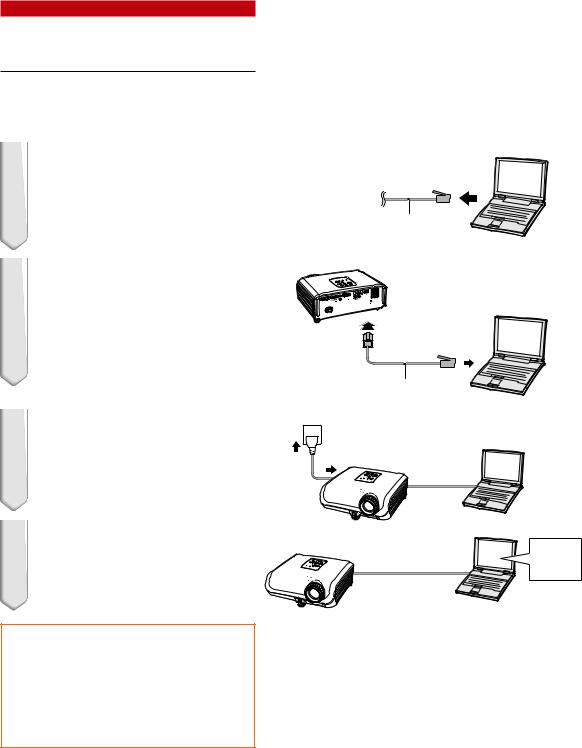
1.Connecting the Projector to a Computer
Establishing a one-to-one connection from the projector to a computer. Using a LAN cable (Category 5, cross-over type) you can configure the projector via the computer.
1 Disconnect the computer’s LAN cable from the existing network.
A LAN cable being connected to the network
2 Connect a LAN cable (a UTP cable, Category 5, cross-over type) to the projector’s LAN terminal and connect the other end of the cable to the computer’s LAN terminal.
LAN cable
(cross-over type, commercially available)
3
4
Plug the power cord into the AC socket of the projector.
Turn on the computer.
ON
 Info
Info
Confirm that the LINK LED on the rear of the projector illuminates. If the LINK LED does not illuminate, check the following :
•The LAN cable is properly connected.
•The power switches of both the projector and the computer are on.
This completes the connection. Now proceed to “2. Setting an IP Address for the Computer”.
 -8
-8
Setting up the Projector Network Environment
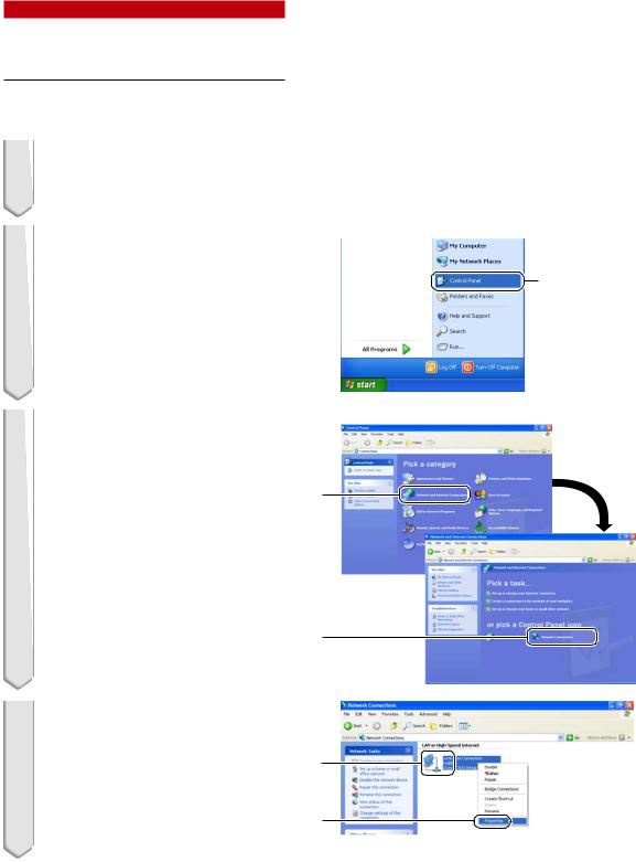
2.Setting an IP Address for the Computer
The following describes how to make settings in Windows® XP (Professional or Home Edition).
1 Log on the network using the administrator’s account for the computer.
2 Click “Start”, and click “Control
Panel”.
2
1
3 Click “Network and Internet Connections”, and click “Network Connections” in the new window.
•This manual uses examples to explain the operations in Category View. If you are using Classic View, double-click “Network Connections”.
1
2
4 Right-click “Local Area Connection” and select “Properties” from the menu. 1
2
 -9
-9

Setting up the Projector Network Environment
5 Click “Internet Protocol (TCP/IP)”,
and click the “Properties” button.
1
2
6 Confirm or change an IP address for the setup computer.
1Confirm and note the current IP address, Subnet mask and Default gateway.
Make sure to note the current IP address, Subnet mask and Default gateway as you will be required to re-
set them later.
2Set temporarily as follows :
IP address : 192.168.150.3 Subnet mask : 255.255.255.0
Default gateway : (Do not input any values.)
 Note
Note
•When “DHCP Client” is set to “OFF” on the projector:
IP address : 192.168.150.2 Subnet mask : 255.255.255.0 Default gateway : 0.0.0.0
7 After setting, click the “OK” button, and then restart the computer.
After confirming or setting, proceed to “3. Setting up Network Connection for the Projector”.
 -10
-10
 Loading...