


AR-M256
Table of contents
 Loading...
Sharp AR-M256, M257, AR-M258, M316, AR-M317 Service Manual. Parts Catalog
...
Parts marked with “ ” are important for maintaining the safety of the set. Be sure to replace these parts with
specified ones for maintaining the safety and performance of the set.
This document has been published to be used
for after sales service only.
The contents are subject to change without notice.
SERVICE MANUAL
CONTENTS
CODE: 00ZARM318/S1E
DIGITAL MULTIFUNCTIONAL
SYSTEM
AR-M256/M257
AR-M258/M316
AR-M317/M318
MODEL
AR-5625/5631
AR-M257/M317
AR-M256/M258
AR-M316/M318
AR-5625/M5631
[1] NOTE FOR SERVICING . . . . . . . . . . . . . . . . . . . . . . . . . . . . . . . . 1-1
[2] CONFIGURATION . . . . . . . . . . . . . . . . . . . . . . . . . . . . . . . . . . . . . 2-1
[3] SPECIFICATIONS . . . . . . . . . . . . . . . . . . . . . . . . . . . . . . . . . . . . . 3-1
[4] CONSUMABLE PARTS . . . . . . . . . . . . . . . . . . . . . . . . . . . . . . . . . 4-1
[5] UNPACKING AND INSTALLATION . . . . . . . . . . . . . . . . . . . . . . . . 5-1
[6] EXTERNAL VIEW AND INTERNAL STRUCTURE . . . . . . . . . . . . 6-1
[7] ADJUSTMENTS, SETTING . . . . . . . . . . . . . . . . . . . . . . . . . . . . . . 7-1
[8] SIMULATION . . . . . . . . . . . . . . . . . . . . . . . . . . . . . . . . . . . . . . . . . 8-1
[9] TROUBLE CODE LIST . . . . . . . . . . . . . . . . . . . . . . . . . . . . . . . . . 9-1
[10] DISASSEMBLY, ASSEMBLY AND MAINTENANCE . . . . . . . . . . 10-1
[11] OTHERS . . . . . . . . . . . . . . . . . . . . . . . . . . . . . . . . . . . . . . . . . . . 11-1
[12] ELECTRICAL SECTION . . . . . . . . . . . . . . . . . . . . . . . . . . . . . . . 12-1

CONTENTS
[1] NOTE FOR SERVICING
1. Warning for servicing. . . . . . . . . . . . . . . . . . . . . . . . . . . . . 1-1
2. Precautions for servicing . . . . . . . . . . . . . . . . . . . . . . . . . . 1-1
3. Note for installing site . . . . . . . . . . . . . . . . . . . . . . . . . . . . 1-1
[2] CONFIGURATION
1. Line of machines and options . . . . . . . . . . . . . . . . . . . . . . 2-1
2. Combination of options list. . . . . . . . . . . . . . . . . . . . . . . . . 2-2
[3] SPECIFICATIONS
1. Basic specifications . . . . . . . . . . . . . . . . . . . . . . . . . . . . . . 3-1
2. Operation specifications . . . . . . . . . . . . . . . . . . . . . . . . . . 3-1
A. Common operation . . . . . . . . . . . . . . . . . . . . . . . . . . . . 3-1
B. Copy mode . . . . . . . . . . . . . . . . . . . . . . . . . . . . . . . . . . 3-1
3. Engine specifications . . . . . . . . . . . . . . . . . . . . . . . . . . . . . 3-2
A. Operation and display section . . . . . . . . . . . . . . . . . . . . 3-2
B. Paper feed, transport, paper exit section . . . . . . . . . . . 3-2
C. Optical (Image scanning) section . . . . . . . . . . . . . . . . . 3-3
D. Scanner (exposure) section . . . . . . . . . . . . . . . . . . . . . 3-3
E. Image process section . . . . . . . . . . . . . . . . . . . . . . . . . 3-3
F. Fusing . . . . . . . . . . . . . . . . . . . . . . . . . . . . . . . . . . . . . . 3-4
G. Drive . . . . . . . . . . . . . . . . . . . . . . . . . . . . . . . . . . . . . . . 3-4
4. Additional functions, copy functions,
and expanded functions. . . . . . . . . . . . . . . . . . . . . . . . . . . 3-4
5. Safety and environmental protection standards . . . . . . . . 3-4
6. Environment conditions . . . . . . . . . . . . . . . . . . . . . . . . . . . 3-5
7. IMC board functions. . . . . . . . . . . . . . . . . . . . . . . . . . . . . . 3-5
8. Printer function
(AR-M256/ M257/ M316/ M317/ 5625/ 5631) . . . . . . . . . . 3-6
A. “Sharp Printer Language with Compression (SPLC)”
Printer function . . . . . . . . . . . . . . . . . . . . . . . . . . . . . . . 3-6
B. Printer driver specification. . . . . . . . . . . . . . . . . . . . . . . 3-6
C. Interface . . . . . . . . . . . . . . . . . . . . . . . . . . . . . . . . . . . . 3-8
D. System outline. . . . . . . . . . . . . . . . . . . . . . . . . . . . . . . . 3-8
9. Printer function (AR-M258/ M318) . . . . . . . . . . . . . . . . . . . 3-8
A. Basic function . . . . . . . . . . . . . . . . . . . . . . . . . . . . . . . . 3-8
[4] CONSUMABLE PARTS
1. Supply system table. . . . . . . . . . . . . . . . . . . . . . . . . . . . . . 4-1
A. SEC/ SECL/ LAG . . . . . . . . . . . . . . . . . . . . . . . . . . . . . 4-1
B. Europe/ East Europe/ Russia/
Australia/ New Zealand . . . . . . . . . . . . . . . . . . . . . . . . . 4-1
C. Asia affiliates . . . . . . . . . . . . . . . . . . . . . . . . . . . . . . . . . 4-1
D. SMEF/ Israel/ Philippines/ Agent. . . . . . . . . . . . . . . . . . 4-1
E. Taiwan. . . . . . . . . . . . . . . . . . . . . . . . . . . . . . . . . . . . . . 4-1
F. Hong Kong . . . . . . . . . . . . . . . . . . . . . . . . . . . . . . . . . . 4-1
G. China. . . . . . . . . . . . . . . . . . . . . . . . . . . . . . . . . . . . . . . 4-1
2. Maintenance parts list . . . . . . . . . . . . . . . . . . . . . . . . . . . . 4-2
A. SDSCA/ SECL/ LAG (AR-M257/ M317) . . . . . . . . . . . . 4-2
B. SEEG/ SUK/ SCA/ SCNZ/ SEA/ SEES/ SEZ/ SEIS/
SEB/ SEN/ SEF/ SMEF/ Russia/ Special country
(AR-M256/ M316, AR-5625/ 5631) . . . . . . . . . . . . . . . . 4-2
C. STCL/ SRH/ SRS/ SRSSC/ SBI/ Agent (All model) . . . 4-3
2. Production number identification . . . . . . . . . . . . . . . . . . . . 4-4
<TD cartridge>. . . . . . . . . . . . . . . . . . . . . . . . . . . . . . . . . . 4-4
<Drum> . . . . . . . . . . . . . . . . . . . . . . . . . . . . . . . . . . . . . . . 4-4
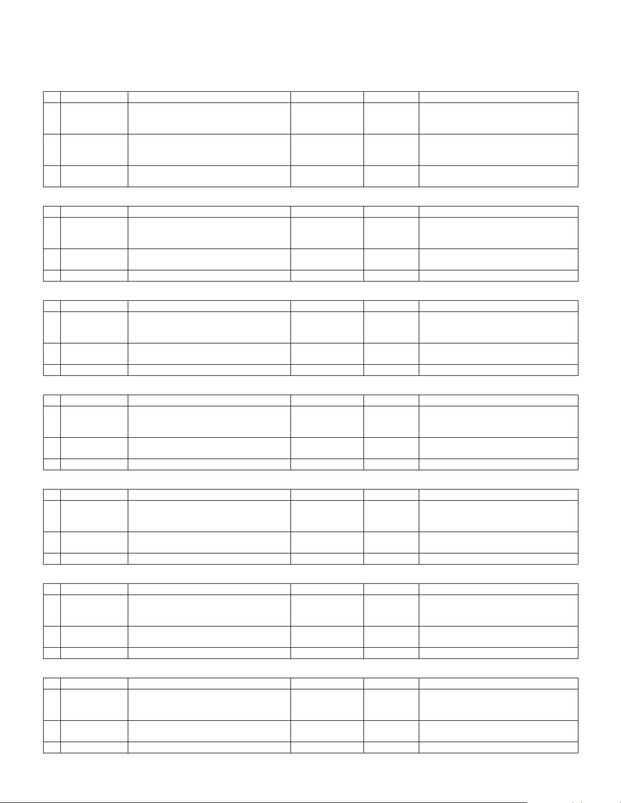
3. Environment conditions . . . . . . . . . . . . . . . . . . . . . . . . . . . 4-4
A. Ambient conditions for transporting . . . . . . . . . . . . . . . . 4-4
B. Ambient storage conditions (sealed). . . . . . . . . . . . . . . 4-4
C. Operating ambient conditions . . . . . . . . . . . . . . . . . . . . 4-4
4. Life (packed conditions). . . . . . . . . . . . . . . . . . . . . . . . . . . 4-4
[5] UNPACKING AND INSTALLATION
1. Installation. . . . . . . . . . . . . . . . . . . . . . . . . . . . . . . . . . . . . . 5-1
A. Environment . . . . . . . . . . . . . . . . . . . . . . . . . . . . . . . . . . 5-1
B. Power source . . . . . . . . . . . . . . . . . . . . . . . . . . . . . . . . . 5-1
C. Transport . . . . . . . . . . . . . . . . . . . . . . . . . . . . . . . . . . . . 5-1
D. Other precautions. . . . . . . . . . . . . . . . . . . . . . . . . . . . . . 5-2
2. Removal of protective material and fixing screw . . . . . . . . 5-2
3. Removal and storage of fixing pin . . . . . . . . . . . . . . . . . . . 5-2
4. Developer cartridge installation . . . . . . . . . . . . . . . . . . . . . 5-3
5. Toner cartridge installation . . . . . . . . . . . . . . . . . . . . . . . . . 5-3
6. Toner density sensor level adjustment . . . . . . . . . . . . . . . . 5-4
7. Tray paper size setting . . . . . . . . . . . . . . . . . . . . . . . . . . . . 5-4
A. Trays 1 – 4 . . . . . . . . . . . . . . . . . . . . . . . . . . . . . . . . . . . 5-4
B. Manual feed tray. . . . . . . . . . . . . . . . . . . . . . . . . . . . . . . 5-4
8. Installation of options . . . . . . . . . . . . . . . . . . . . . . . . . . . . . 5-5
A. AR-P27. . . . . . . . . . . . . . . . . . . . . . . . . . . . . . . . . . . . . . 5-5
B. AR-PK1N . . . . . . . . . . . . . . . . . . . . . . . . . . . . . . . . . . . . 5-6
C. AR-PF1/PF2. . . . . . . . . . . . . . . . . . . . . . . . . . . . . . . . . . 5-7
D. MX-NSX1 . . . . . . . . . . . . . . . . . . . . . . . . . . . . . . . . . . . . 5-7
F. AR-SM5/SM6 . . . . . . . . . . . . . . . . . . . . . . . . . . . . . . . . . 5-8
[6] EXTERNAL VIEW AND INTERNAL STRUCTURE
1. Name and function of each section . . . . . . . . . . . . . . . . . . 6-1
A. External view . . . . . . . . . . . . . . . . . . . . . . . . . . . . . . . . . 6-1
B. Internal structure . . . . . . . . . . . . . . . . . . . . . . . . . . . . . . 6-2
C. Operation panel . . . . . . . . . . . . . . . . . . . . . . . . . . . . . . . 6-3
D. Job status screen
(common to copy, print, network scan and fax) . . . . . . . 6-4
E. Motor, Solenoid, Clutch . . . . . . . . . . . . . . . . . . . . . . . . . 6-5
F. Sensor . . . . . . . . . . . . . . . . . . . . . . . . . . . . . . . . . . . . . . 6-5
G. PWB unit . . . . . . . . . . . . . . . . . . . . . . . . . . . . . . . . . . . . 6-6
H. Section . . . . . . . . . . . . . . . . . . . . . . . . . . . . . . . . . . . . . . 6-6
[7] ADJUSTMENTS, SETTING
1. List of adjustment items . . . . . . . . . . . . . . . . . . . . . . . . . . . 7-1
2. Copier adjustment. . . . . . . . . . . . . . . . . . . . . . . . . . . . . . . . 7-1
A. Process section . . . . . . . . . . . . . . . . . . . . . . . . . . . . . . . 7-1
B. Mechanism section. . . . . . . . . . . . . . . . . . . . . . . . . . . . . 7-3
C. Image density (exposure) adjustment . . . . . . . . . . . . . . 7-9
[8] SIMULATION
(Diagnostics, setup, adjustment value input, data display)
1. Outline and purpose . . . . . . . . . . . . . . . . . . . . . . . . . . . . . . 8-1
2. Code-type simulation . . . . . . . . . . . . . . . . . . . . . . . . . . . . . 8-1
A. Operating procedures and operations . . . . . . . . . . . . . . 8-1
B. How to change the simulation adjustment value set
by the touch panel in the adjustment value entry
process. . . . . . . . . . . . . . . . . . . . . . . . . . . . . . . . . . . . . . 8-1
3. Simulation code list. . . . . . . . . . . . . . . . . . . . . . . . . . . . . . . 8-3
4. Details. . . . . . . . . . . . . . . . . . . . . . . . . . . . . . . . . . . . . . . . . 8-6
[9] TROUBLE CODE LIST
1. List . . . . . . . . . . . . . . . . . . . . . . . . . . . . . . . . . . . . . . . . . . . 9-1
2. Self diagnostics . . . . . . . . . . . . . . . . . . . . . . . . . . . . . . . . . 9-2

[10] DISASSEMBLY, ASSEMBLY AND MAINTENANCE
1. Maintenance table . . . . . . . . . . . . . . . . . . . . . . . . . . . . . . 10-1
(For 25cpm) . . . . . . . . . . . . . . . . . . . . . . . . . . . . . . . . . . . 10-1
(For 31cpm) . . . . . . . . . . . . . . . . . . . . . . . . . . . . . . . . . . . 10-2
2. Counter clear . . . . . . . . . . . . . . . . . . . . . . . . . . . . . . . . . . 10-3
3. List of disassembly and assembly . . . . . . . . . . . . . . . . . . 10-3
4. Details of disassembly and assembly . . . . . . . . . . . . . . . 10-3
A. Process unit . . . . . . . . . . . . . . . . . . . . . . . . . . . . . . . . 10-3
B. Developing section . . . . . . . . . . . . . . . . . . . . . . . . . . . 10-5
C. Fusing section . . . . . . . . . . . . . . . . . . . . . . . . . . . . . . . 10-6
D. Optical section. . . . . . . . . . . . . . . . . . . . . . . . . . . . . . . 10-8
E. Paper feed section . . . . . . . . . . . . . . . . . . . . . . . . . . . 10-9
F. Side door unit . . . . . . . . . . . . . . . . . . . . . . . . . . . . . . 10-15
G. 1st paper exit unit . . . . . . . . . . . . . . . . . . . . . . . . . . . 10-16
H. 2nd paper exit unit. . . . . . . . . . . . . . . . . . . . . . . . . . . 10-17
I. Laser unit . . . . . . . . . . . . . . . . . . . . . . . . . . . . . . . . . 10-18
J. Power unit . . . . . . . . . . . . . . . . . . . . . . . . . . . . . . . . . 10-18
K. PWB . . . . . . . . . . . . . . . . . . . . . . . . . . . . . . . . . . . . . 10-19
L. Ozone filter . . . . . . . . . . . . . . . . . . . . . . . . . . . . . . . . 10-21
M. Drive section. . . . . . . . . . . . . . . . . . . . . . . . . . . . . . . 10-21
N. Transport section . . . . . . . . . . . . . . . . . . . . . . . . . . . 10-23
O. Operation section . . . . . . . . . . . . . . . . . . . . . . . . . . . 10-24
P. Switch . . . . . . . . . . . . . . . . . . . . . . . . . . . . . . . . . . . . 10-24
[11] OTHERS
1. Flash ROM version-up procedure . . . . . . . . . . . . . . . . . . 11-1
A. Program download method
(for Copier, and fax program) . . . . . . . . . . . . . . . . . . . 11-1
B. Printer Control Board firmware download method . . . 11-2
C. Others (Troubleshooting) . . . . . . . . . . . . . . . . . . . . . . 11-3
2. Key operator program list . . . . . . . . . . . . . . . . . . . . . . . . 11-3
A. Common program of digital copier . . . . . . . . . . . . . . . 11-3
B. Copy function setting program . . . . . . . . . . . . . . . . . . 11-4
C. Printer function setting program . . . . . . . . . . . . . . . . . 11-4
D. Network scanner function setting program . . . . . . . . . 11-5
3. E-mail Status/ E-mail Alerts. . . . . . . . . . . . . . . . . . . . . . . 11-6
A. Basic functions . . . . . . . . . . . . . . . . . . . . . . . . . . . . . . 11-6
B. Main body specifications . . . . . . . . . . . . . . . . . . . . . . . 11-6
C. Printer controller specifications . . . . . . . . . . . . . . . . . . 11-6
D. Handling of transmission data. . . . . . . . . . . . . . . . . . . 11-6
[12] ELECTRICAL SECTION
1. Block diagram . . . . . . . . . . . . . . . . . . . . . . . . . . . . . . . . . 12-1
2. Actual wiring diagram . . . . . . . . . . . . . . . . . . . . . . . . . . . 12-2

AR-M256/M257/M258/M316/M317/M318/5625/5631 NOTE FOR SERVICING 1 - 1
[1] NOTE FOR SERVICING
This Service Manual uses some photographs to assure safe operation.
Please understand the meanings of photographs before servicing.
1. Warning for servicing
1) Be sure to connect the power cord only to a power outlet that
meets the specified voltage and current requirements.
Avoid complex wiring, which may lead to a fire or an electric shock.
2) If there is any abnormality such as smoke or an abnormal smell,
interrupt the job and disconnect the power plug.
It may cause a fire or an electric shock.
3) Be sure the machine is properly grounded. Failure to ground the
machine properly may result in an electric shock or fire.
To protect the machine and the power unit from lightening, ground-
ing must be made.
4) When connecting the ground wire, never connect it to the following
points as it may cause an explosion, fire, or an electric shock:
• Gas tube
• Lightning conductor
• A water pipe or a water faucet, which is not recognized as a
grounding object by the authorities.
• Grounding wire for telephone line
5) Do not damage, break, or stress the power cord. Do not put heavy
objects on the power cord. Do not bend or pull the cord forcefully. It
may cause a fire or electric shock.
6) Keep the power cable away from a heat source.
Do not insert the power plug with dust on it into a power outlet.
It may cause a fire or an electric shock.
7) Do not put a receptacle with water in it or a metal piece which may
drop inside the machine.
It may cause a fire or an electric shock.
8) Do not touch the power plug, insert a telephone jack, perform ser-
vice or operate the machine with wet or oil hands. It may cause an
electric shock.
2. Precautions for servicing
1) When servicing, disconnect the power plug, the printer cable, the
network cable, and the telephone line from the machine, except
when performing the communication test, etc.
It may cause an injury or an electric shock.
2) There is a high temperature area inside the machine. Use extreme
care when servicing.
3) There is a high voltage section inside the machine which may
cause an electric shock . Be careful when servicing.
4) Do not disassemble the laser unit. Do not insert a reflective mate-
rial such as a screwdriver in the laser beam path.
It may damage eyes by reflection of laser beams.
5) When servicing the machine while operating, be careful not to
make contact with chains, belts, gear, and any other moving parts.
6) Do not leave the machine with the cabinet disassembled.
Do not allow any person other than a serviceman to touch inside
the machine. It may cause an electric shock, a burn, or an injury.
7) When servicing, do not breathe toner, developer, and ink exces-
sively. Do not get them in the eyes.
If toner, developer, or ink enters you eyes, wash it away with water
immediately, and consult a doctor if necessary.
8) The machine has got sharp edges inside. Be careful not to dam-
age fingers when servicing.
9) Do not throw toner or a toner cartridge in a fire. Otherwise, toner
may pop and burn you.
10) When replacing the lithium battery on the PWB, use only the spec-
ified battery. If a battery of different specification is used, it may not
be compatible and cause breakdown or malfunction of the
machine.
11) When carrying an electric unit or a PWB, use an anti-static (elec-
tricity) bag. Failure to do so may cause component failure or
machine malfunction.
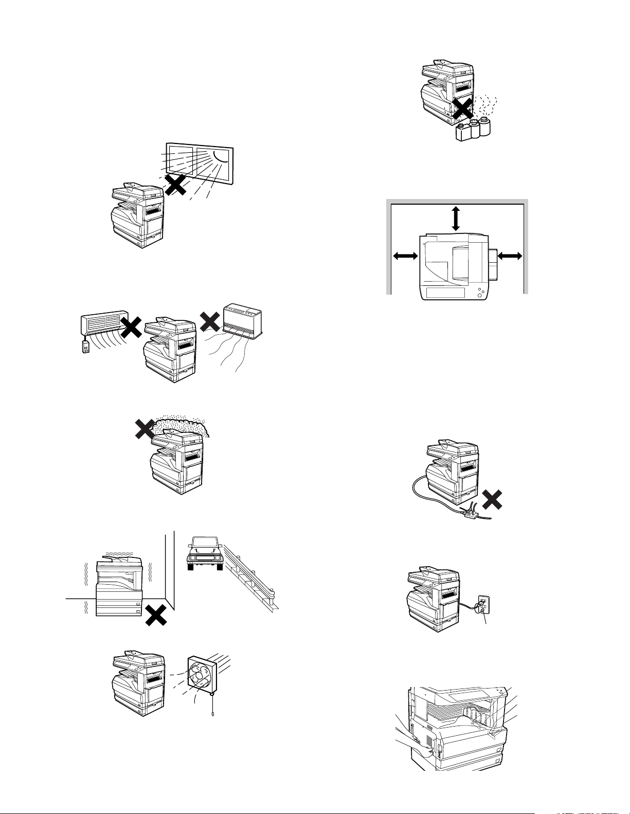
3. Note for installing site
Do not install the machine at the following sites.
1) Place of high temperature, high humidity, low temperature, low
humidity, place under an extreme change in temperature and
humidity.
Paper may get damp and form dews inside the machine, causing
paper jam or copy dirt.
For operating and storing conditions, refer to the specifications
described later.
2) Place of much vibrations
It may cause a breakdown.
3) Poorly ventilated place
An electro-static type copier will produce ozone inside it.
The quantity of ozone produced is designed to a low level so as
not to affect human bodies. However, continuous use of such a
machine may produce a smell of ozone. Install the machine in a
well ventilated place, and ventilate occasionally.
4) Place of direct sunlight.
Plastic parts and ink may be deformed, discolored, or may undergo
qualitative change.
It may cause a breakdown or copy dirt.
5) Place which is full of organic gases such as ammonium
The organic photoconductor (OPC) drum used in the machine may
undergo qualitative change due to organic gases such as ammo-
nium.
Installation of this machine near a diazo-type copier may result in
dirt copy.
6) Place of much dust
When dusts enter the machine, it may cause a breakdown or copy
dirt.
7) Place near a wall
Some machine require intake and exhaust of air.
If intake and exhaust of air are not properly performed, copy dirt or
a breakdown may be resulted.
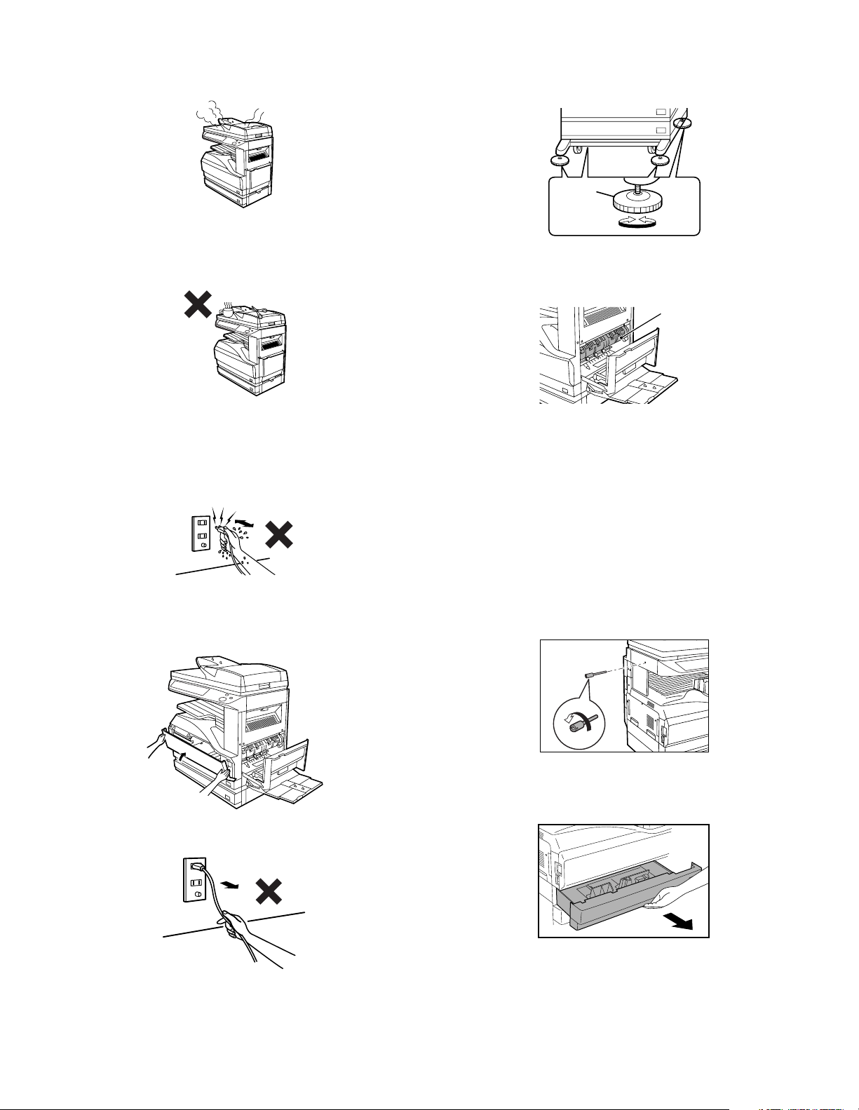
8) Unstable or slant surface
If the machine drops or fall down, it may cause an injury or a break-
down.
If there are optional paper desk and the copier desk specified, it is
recommendable to use them.
When using the optional desk, be sure to fix the adjuster and lock
the casters.
WARNING: If this WARNING should be ignored, a serious danger
to life or a serious injury may result.
CAUTION: If this CAUTION should be ignored, injury or damage
to property could result.

AR-M256/M257/M258/M316/M317/M318/5625/5631 CONFIGURATION 2 - 1
[2] CONFIGURATION
1. Line of machines and options
Paper feed unit (500 Seets)
[AR-D30]
Paper feed unit (500c2 Seets)
[AR-D31]
Finisher
[AR-FN5A]
Saddle stitch finisher
[AR-F14N]
Staple cartridge
[AR-SC2]
Staple cartridge
[AR-SC1]
Punch unit
[AR-PN1A/B/C/D]
Reversing single pass feeder
[AR-RP7]
Document cover
[AR-VR6]
[AR-M257/M317]
[RSPF]
[AR-P27]
Printer expantion kit (PCL)Expantion memory board
PS3 expantion kit
Network scanner
expantion kit
Sharpdesk
license kit
Application integration
module kit
[AR-SM5](256MB)
[AR-SM6](512MB)
FAX expantion kitData security kit FAX memory (8MB)
[AR-FX7]
[AR-PF1] [AR-PF2]
[AR-MM9]
[AR-PK1N][MX-NSX1]
[MX-USX1/
MX-USX5/
MX-US10/
MX-US50/
MX-USA0]
[MX-AMX1]
[AR-FR24]
(For 25cpm)
[AR-FR25]
(For 31cpm)
[AR-FR24U]
(For 25cpm)
[AR-FR25U]
(For 31cpm)
Copier/Printer (SPLC) model
Copier/Printer (SPLC) model
[AR-M258/M318]
Copier/Printer (PCL)
Network model
[AR-M256/M316]
[AR-5625/5631]
[AR-M256/M316/M257/M317/M258/M318]
[AR-M256/M316/M257/M317]
Job separator tray
[AR-TR3]
Barcode font kit Flash ROM kit
[Authentication
version]
[Commercial
version]

AR-M256/M257/M258/M316/M317/M318/5625/5631 CONFIGURATION 2 - 2
2. Combination of options list
F : Installable
✕: Not available
Section
Option Main unit Model
Note
Item Model
AR-M256/
M316
AR-M257/
M317
AR-M258/
M318
AR-5625/
5631
Automatic document
feeder and OC
Document feeder AR-RP7 F Standard FF
Document cover AR-VR6 F ✕ FF
Paper feed system Paper feed unit (500 sheets) AR-D30 FFFF500 x 1 (80g/m
2
)
Paper feed unit
(500 x 2 sheets)
AR-D31 FFFF500 x 2 (80g/m
2
)
Paper exit system Job separator tray AR-TR3 FFFF
Finisher AR-FN5A FFFF
Staple cartridge AR-SC1 FFFFFor AR-FN5A
Saddle stitch finisher AR-F14N FFFF
Staple cartridge AR-SC2 FFFFFor AR-F14N
Punch unit AR-PN1A FFFF
AR-PN1B FFFF
AR-PN1C FFFF
AR-PN1D FFFF
FAX system FAX expansion kit AR-FX7 FFFF
FAX memory (8MB) AR-MM9 FFFF
Printer system Printer expansion kit (PCL) AR-P27 FFStandard ✕
Bar code font kit AR-PF1 FFF✕ AR-P27 must be installed.
Flash ROM kit AR-PF2 FFF ✕
PS3 expansion kit AR-PK1N FFF✕
Memory board 256MB expansion memory
board
AR-SM5 FFFF
512MB expansion memory
board
AR-SM6 FFFF
Software Network scanner expansion
kit
MX-NSX1 FFF✕ AR-P27 must be installed.
Sharpdesk 1 license kit MX-USX1 FFF✕
Sharpdesk 5 license kit MX-USX5 FFF✕
Sharpdesk 10 license kit MX-US10 FFF✕
Sharpdesk 50 license kit MX-US50 FFF✕
Sharpdesk 100 license kit MX-USA0 FFF✕
Application integration
module kit
MX-AMX1 FFF✕ AR-P27 must be installed.
Data security Data security kit
(Commercial version)
AR-FR24U FFFFFor 25cpm
AR-FR25U FFFFFor 31cpm
Data security kit
(Authentication version)
AR-FR24 FFFFFor 25cpm
AR-FR25 FFFFFor 31cpm
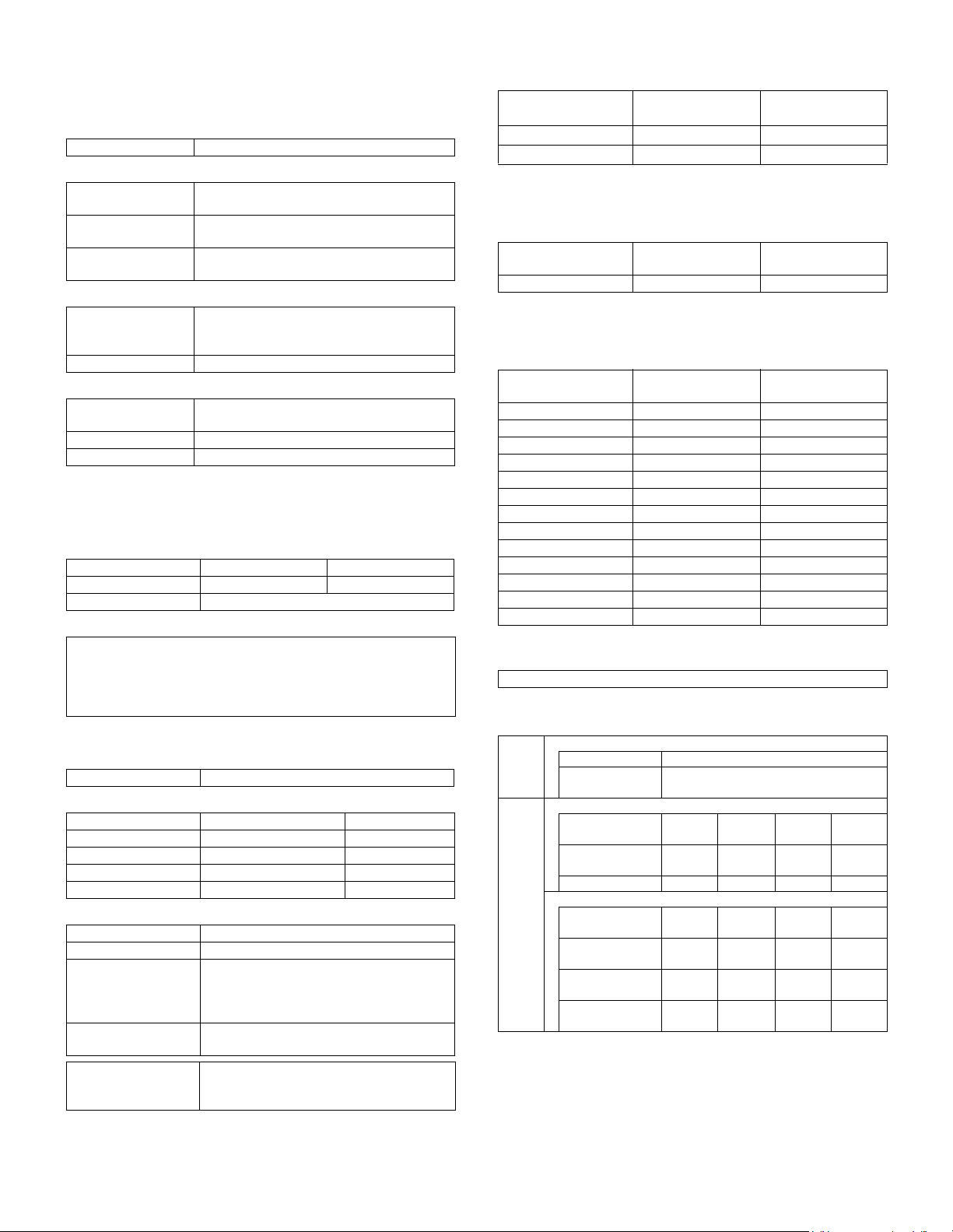
AR-M256/M257/M258/M316/M317/M318/5625/5631 SPECIFICATIONS 3 - 1
[3] SPECIFICATIONS
1. Basic specifications
(1) Type
(2) External dimensions
(3) Weight
(4) Power supply
2. Operation specifications
A. Common operation
(1) Warm up time
(2) Jam recovery time
B. Copy mode
(1) Document size
(2) Picture quality mode
(3) Copy magnification ratio
(4) Job speed
a. First Copy Time
∗ Measurement conditions:
When paper of A4/ 8.5 x 11 is fed from the main unit tray, the poly-
gon motor is rotating.
b. Copy speed
∗ S to S: A4/ 8.5 x 11 documents 11 sheets, copy 1 sets
(First copy is not included.)
Monochrome scan resolution: 600 x 600dpi (Default)
c. Multi copy speed (sheets/ minute)
∗ Same speed for Normal/ Enlargement/ Reduction.
(5) Max. multi-copy (print) quantity
(6) Picture quality
A. Resolution
Machine Type Desktop type
Floor to OC top
surface
623 (W) x 615 (D) x 640.5 (H)mm
(24.5 (W) x 24.2 (D) x 25.2 (H) inch)
Floor to Glass
surface
623 (W) x 615 (D) x 665 (H)mm
(24.5 (W) x 24.2 (D) x 26.2 (H) inch)
Floor to RSPF
surface
623 (W) x 615 (D) x 786 (H)mm
(24.5 (W) x 24.2 (D) x 30.9 (H) inch)
AR-M256/ M258/
M316/ M318/ 5625/
5631
49.2 kg (with OC)
AR-M257/ M317 55 kg
Voltage 100V: 110V/ 120V to 127V
200V: 220V to 240V
Frequency 50/ 60Hz common
Power switch One power source
25 sheet model 31 sheet model
Warm-up time 23 sec. or less 25 sec. or less
Pre-heat function Yes
About 10sec.
However, the conditions for warming up of fusing and toner control
are excluded.
(Condition: Leaving the machine for 60 sec after opening the door,
standard condition, polygon stop.)
Max. document size A3 paper (11" × 17")
Picture quality mode Density adjustment step Toner save mode
Text Auto mode 1 step Selectable
Text mode 5 steps Selectable
Text/ Photo mode 5 steps Selectable
Photo mode 5 steps —
Copy magnification ratio
Magnification range/ fixed magnification
Zoom width 25 to 400% (50 to 200% for RSPF)
Fixed magnification
mode
AB Series : 25, 50, 70, 81, 86, 100, 115,
122, 141, 200, 400%
Inch Series: 25, 50, 64, 77, 100, 121, 129,
200, 400%
Independent
magnification width
25 to 400% for horizontal/ vertical
(50 to 200% for RSPF)
Magnification
precision
Normal copy: 100%±1.0%
Enlargement copy: Set magnification ±1.0%
Reduction copy: Set magnification ±1.0%
Platen/ DSPF
AR-M256/ M257/
M258/ 5625
AR-M316/ M317/
M318/ 5631
Platen Less than 4.8 sec. Less than 4.8 sec.
RSPF Less than 9.3 sec. Less than 9.3 sec.
Engine
AR-M256/ M257/
M258/ 5625
AR-M316/ M317/
M318/ 5631
S to S 25 cpm (100%) 27 cpm (87%)
Document Size
AR-M256/ M257/
M258/ 5625
AR-M316/ M317/
M318/ 5631
A3 13 17
B4 15 20
A4 25 31
A4R 18 24
B5 25 31
B5R 20 24
A5 25 31
11" × 17" 13 17
8-1/ 2" × 14" 14 20
8-1/ 2" × 13" 15 20
8-1/ 2" × 11" 25 31
8-1/ 2" × 11"R 18 24
5.5 × 8.5 25 31
999 sheets
Scan
resol
ution
(dpi)
Copy mode
Platen 400 × 600dpi
RSPF 400 × 600dpi
Input
and
send
resol
ution
(dpi)
Fax send mode
Select mode
Normal
text
Fine
text
Super
fine test
Ultra
fine text
Transmission
resolution
203.2 ×
97.8
203.2 ×
195.6
203.2 ×
391
406.4 ×
391
Half tone × FFF
Scanner mode
Select mode 200 ×
200
300 ×
300
400 ×
400
600 ×
600
Input resolution:
OC
600 ×
600
600 ×
600
600 ×
600
600 ×
600
Input resolution:
RSPF
600 ×
367
600 ×
367
600 ×
367
600 ×
367
Transmission
resolution
200 ×
200
300 ×
300
400 ×
400
600 ×
600
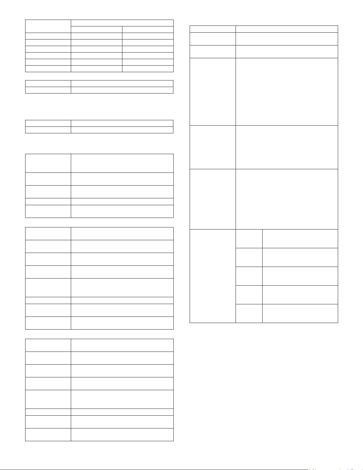
AR-M256/M257/M258/M316/M317/M318/5625/5631 SPECIFICATIONS 3 - 2
b. Gradation
3. Engine specifications
A. Operation and display section
B. Paper feed, transport, paper exit section
(1) Paper feed ability
• Tray 1
• Tray 2
• Manual feed section
∗ Overseas envelopes for check:
#10 Commercial, DL, C5 ("Must be free of passing trouble" with :
Must pass through machine with reliability.)
(Evaluation reference envelope)
∗ Types of gift wrapping paper for check:
Aioi Envelope gift wrapping paper A3, B4, A4, B5, Mino Size, Hanshi
(“Must be free of passing trouble” with : Must pass through machine
with reliability.)
Note: FAX data print from manual paper feed cannot be performed.
Copy magnification
ratio
Position
Center Corners
25% to 49% — —
50% to 69% 3.2 line/mm 2.8 line/mm
70% to 94% 3.6 line/mm 3.2 line/mm
95% to 105% 5.0 line/mm 4.5 line/mm
106% to 141% 5.0 line/mm 4.5 line/mm
142% to 400% 5.0 line/mm 4.5 line/mm
Read 256 gradations
Write 2 gradations
Display unit Dot matrix LCD, Touch panel
Operation system Button switch system
Type 2-stage paper feed tray + multi manual feed
(Can be extended up to 4 stages by installation
of the options.)
Paper feed method Paper is fed from the above by the front
loading system.
Dehumidification
heater
No
Paper size label Yes
Maximum weight
setting
No
Paper size A3/ B4/ A4/ A4R/ B5/ B5R/ A5/ 16K/ 16KR/
11 × 17/ 8.5 × 14/ 8.5 × 13/ 8.5 × 11/ 8.5 × 5.5
Paper size change
method
Changeable by the user.
(By the operation on the LCD panel)
Paper type setting Normal paper, Recycled paper, Letterhead,
Color paper
Paper size setting
when shipping
AB series: A4
Inch series: 8.5 x 11
Allowable paper
type and weight for
paper feed
56 to 105g/
m
2
/ 15 to 28lbs Bond
Paper capacity 500 sheets (80g/
m
2
paper) (Plain paper)
Paper type Plain paper (56 to 80g/
m
2
), Normal paper
(80 to 105g/
m
2
), Letterhead, Color paper
Paper remaining
detection
No (Only paper empty detection)
Paper size A3/ B4/ A4/ A4R/ B5R/ 16KR/ 8K/11 × 17/
8.5 × 14/ 8.5 × 13/ 8.5 × 11/ 8.5 × 11R
Paper size change
method
Changeable by the user.
(By the operation on the LCD panel)
Paper type setting Normal paper, Recycled paper, Letterhead,
Color paper
Paper size setting
when shipping
AB series: A4
Inch series: 8.5 x 11
Allowable paper
type and weight for
paper feed
56 to 105g/
m
2
/ 15 to 28lbs Bond
Paper capacity 500 sheets (80g/
m
2
paper) (Plain paper)
Paper type Plain paper (56 to 80g/
m
2
), Normal paper
(80 to 105g/
m
2
), Letterhead, Color paper
Paper remaining
detection
No (Only paper empty detection)
Transport reference Center reference
Paper size display AB series: A3 to A6R, Postcard
Inch series: 11 x 17 to 5.5 x 8.5
Paper size setting A3/ A4, 11 x 17, B4/ B5, 8.5 x 14, A4R/ A5,
B5R, A5R, 5.5 x 8.5
Paper type Multi paper feed:
Plain paper (52 to 80g/
m
2
), recycled paper,
OHP, label sheet, gift wrapping paper,
postcards, double postal card (no folding line),
envelope, coarse paper, thick paper
Single paper feed:
Plain paper (52 to 128g/m
2
), recycled paper,
OHP, label sheet, gift wrapping paper,
postcards, double postal card (no folding line),
envelope, postcard paper, coarse paper, No. 2
master drawing, Thick paper (Max. 200g/m
2
)
Allowable paper
type and weight for
paper feed
Multi paper feed:
Plain paper (52 to 128g/
m
2
), special paper,
thick paper (Max. 200g/
m
2
)
Single paper feed:
Plain paper, special paper, No. 2 master
drawing, thick paper (Max. 200g/
m
2
)
52 to 200g/
m
2
(14 to 54lbs)
Paper capacity
(Multi paper feed)
Normal paper: 100 sheets
(Plain paper: 52 to 80g/
m
2
)
Recycled paper/ coarse paper: 100 sheets
Postcards/ Double postal card
(no folding line):
30 sheets
Thick paper (Max. 200g/
m
2
): 30 sheets
OHP/ Label sheet/ Gift wrapping paper: 40
sheets
Envelope
(AB series: 10 sheets, Inch series 5 sheets)
Paper size
detection
Automatic
detection-
AB
A3 / A4 / 11 x 17 / 8.5 × 14/
8.5 x 13 */ 8.5 x 11 / 8.5 x 11R /
5.5 x 8.5
Automatic
detection-
inch
A3 / B4 / A4 / A4R / A5 / 11 x 17 /
8.5 × 14/ 8.5 x 13 */ 8.5 x 11
Automatic
detection-
China
A3 / B4 / A4 / A4R / B5 / B5R /
A5 / 8K / 16K
Automatic
detection-
Ta iw a n
A3 / B4 / A4 / A4R / B5 / B5R /
A5 / 11 × 17/ 8.5 x 14 / 8.5 x 11
Detection
disregard
setting
Ye s

AR-M256/M257/M258/M316/M317/M318/5625/5631 SPECIFICATIONS 3 - 3
• Duplex
(2) Finishing ability
(3) Job separator exit tray (AR-TR3)
C. Optical (Image scanning) section
(1) Type
(2) Document reference position
(3) Resolution
(4) Gradation
(5) Original size/ Scanning area
a. Max. original size
(6) Scanning speed
(7) Light source (lamp)
(8) Read sensor
D. Scanner (exposure) section
(1) Resolution
(2) Gradation
(3) Laser unit specifications
E. Image process section
Type Switchback system
Paper size A3, B4, A4, A4R, B5, B5R, 11 x 17, 8.5 x 14,
8.5 x 13, 8.5 x 11, 8.5 x 11R
Type and weight of
paper which can be
passed
56 to 105g/
m
2
/ 15 to 21.3lbs Bond
Duplex print from manual paper feed can be
performed.
(Except for heavy paper, OHP sheet, and
special paper.)
∗ Judgment is made by setting the paper type
on the operation panel.
Paper exit section Paper exit tray (1 tray)
Paper exit face Face down
Capacity 500 sheets (80g/
m
2
paper)
Full detection No
Paper detection Yes
Finishing Yes
Offset function Depending on the shifter.
Stapling Available when the finisher is installed.
Condition In case of Optional function (printer, FAX) is
set up as MFD.
Simultaneous
wrapping in kit
Job separator tray
Setting manual book
Simultaneous
wrapping
Setting manual book
Function This exit tray is set up above main exit tray, and
can separate copier exit, printer exit and FAX
exit.
Many of tray 1 (this tray can not set up more than 2)
Separator system By control of main machine
Exit paper size All sizes of paper except for postcards (A6)
and envelopes.
Exit paper weight 52 to 128g/m
2
(14 to 34.1lbs)
Paper pass Center (same as main unit)
Exit area/ finishing Face-down paper exit to the upper surface of
the main unit paper exit section
Machine weight 0.6 kg
Exit capacity 100 sheets (80g/m
2
paper)
Tray full detector Yes
Concept of function
Upper exit tray
(Job separator)
Copy/ FAX/ Printer
(This setting can be done by users.)
Lower exit tray
(main machine
exit tray)
Copy/ Printer/ FAX
(This setting can be done by users.)
Document table Document table fixed type (Flat-bed type)
Document table Rear left reference
Main scanning direction Sub scanning direction
400 dpi 600 dpi
256 gradations (8-bit)
A3 paper (11" × 17")
122mm/sec (600 dpi: magnification ratio 100%)
(AR-M256/ M257/ M258/ 5625)
145mm/sec (600 dpi: magnification ratio 100%)
(AR-M316/ M317/ M318/ 5631)
Type None-electrode xenon lamp
Drive voltage 1.5 kV
Type Reduction optical system image sensor (CCD)
Monochrome
Main scanning direction Sub scanning direction
600 dpi 600 dpi
2 gradations
r.p.m. 28,819 rpm (26 sheet model/FAX output)
34,252 rpm (31 sheet model)
Mirror surfaces 6 faces
Laser power 0.16mW (26 sheet model/FAX output)
0.18mW (31 sheet model)
Laser beam size 60
µ (Main scan) x 70µ (Sub scan)
Laser wave length 785nm
Imaging speed 600 dpi: 122 mm/sec.
(AR-M256/ M257/ M258/ 5625)
600 dpi: 145 mm/sec.
(AR-M316/ M317/ M318/ 5631)
Photo
conductor
Type OPC drum (dia. 30mm)
LIFE 25 sheet model: 75,000 sheets
31 sheet model: 100,000 sheets
Toner Type Developer (Black)
LIFE 25,000 sheets
(Toner, life: 25k,
Developer life: 75k (26 sheet model)
100k (31 sheet model))
Charge System Charged saw-tooth
Voltage 560
µA constant electric current
Transfer System Transfer roller
Voltage 18
µA (electric current)
Exposure None-electrode xenon lamp
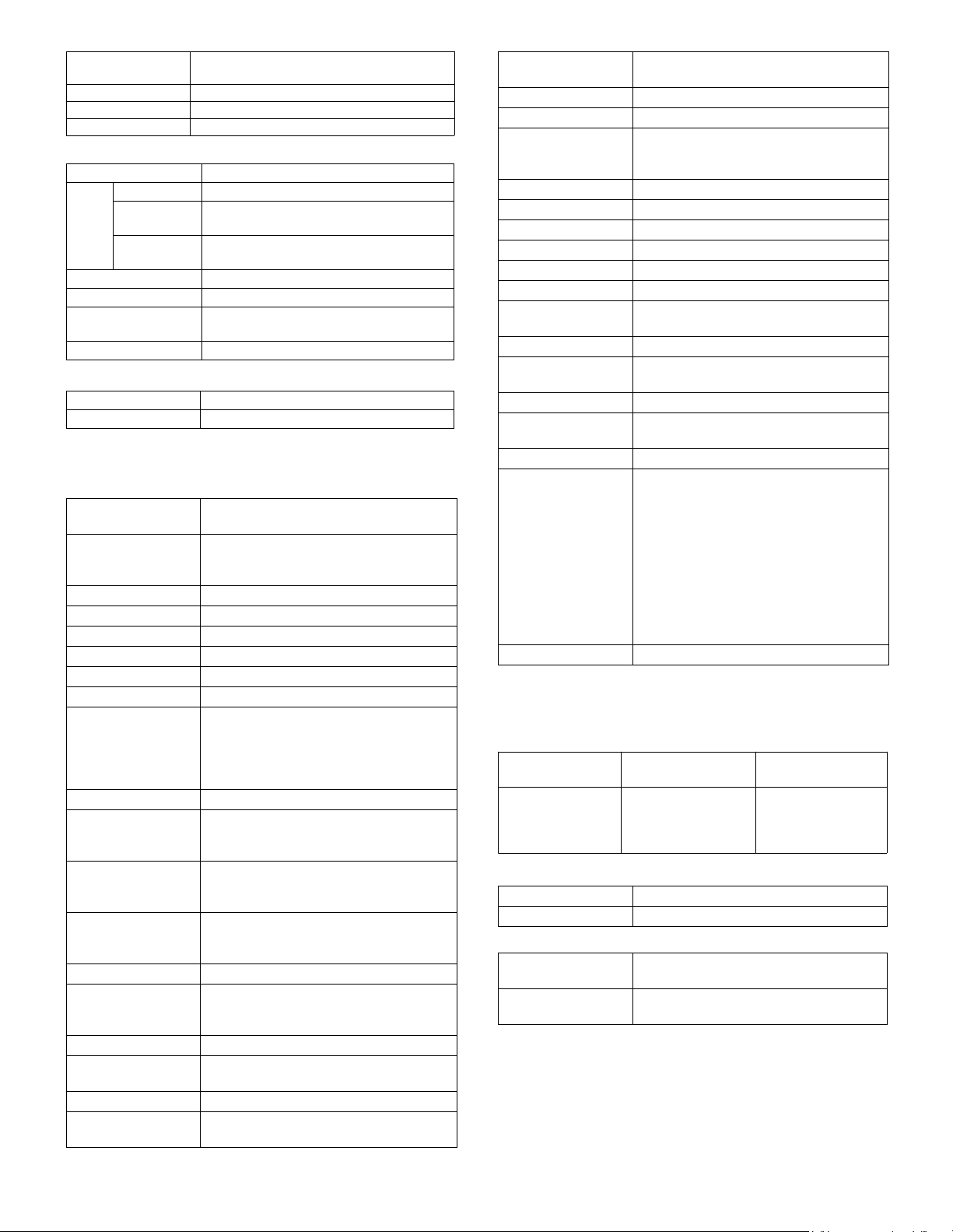
AR-M256/M257/M258/M316/M317/M318/5625/5631 SPECIFICATIONS 3 - 4
F. Fusing
G. Drive
4. Additional functions, copy functions,
and expanded functions
5. Safety and environmental protection
standards
(1) Safety standards
(2) Ozone level
(3) Noise level
Developing Dry, 2-component magnetic brush
development
Separation (–) DC scorotron
Discharge —
Cleaning Contacted blade
Type Heat roller
Lamp Type Halogen lamp
Voltage 100V: 110V/ 120V to 127V
200V: 220V to 240V
Power
consumption
Main : 650W
Sub : 550W
Fusing temperature 185° (600 dpi)
Heat roller Teflon coated roller
Pressure roller Silicone rubber roller with re-engerized
cube
Separation system Natural separation (with pawl)
Drive section Motor
Main motor DC brushless motor
APS (Automatic
paper selection)
Ye s
(No for APS by flow scan with the RSPF)
AMS (Automatic
magnification ratio
selection)
Ye s
(No for AMS by flow scan with the RSPF)
Stream feeding mode Yes
Job build function Yes (Copy/ Scan)
Auto tray switching Yes (No for manual paper feed)
Memory copy Yes (1 page memory provided as standard)
Rotation copy Yes
E-sort Yes
XY zoom Yes
When the OC is used: Landscape/ Portrait
25 – 400%
When the RSPF is used: Landscape/ Portrait
50 – 200%
1 set 2 copy Yes (No for enlargement)
Binding margin Yes
Default AB series: 0 – 20 mm (Unit of 1 mm)
Inch series: 0 – 1 inch (Unit of 1/ 8 inch)
Edge erase Yes
Default AB series: 0 – 20 mm (Unit of 1 mm)
Inch series: 0 – 1 inch (Unit of 1/ 8 inch)
Center frame erase Yes
Default AB series: 0 – 20 mm (Unit of 1 mm)
Inch series: 0 – 1 inch (Unit of 1/ 8 inch)
Booklet copy No
White/ black reversion Yes
Whole surface only
(Can be inhibited with the simulation.)
2 in 1/ 4 in 1 Yes (Centering provided)
Sorter Yes
Offset function (shifter or finisher) required
Mix paper feed Yes (Only when this function is set)
Preheating Yes (Conditions are set with the key operator
program.)
Auto power shut off
function
Yes (Conditions are set with the key operator
program.)
Message display Yes
Key operator program Yes
Printer status monitor/
Printer administration
utility
Yes (A PCL printer board is required (TCP/
IP only). To use another protocol, an NIC
card is required.)
Wireless LAN support Yes (A 3rd party part is recommended.)
Coin vendor support Yes (Option only for the models for dealers)
Auditor support Yes
Duplex Yes (Standard)
Total counter Yes
Toner save Yes
Department
management
Yes (100 departments)
Job registration/ call Yes (10 jobs)
Cover paper Yes (Insertion and stapling must be allowed
from manual feed.)
OHP insert paper No
Self print function Yes (The service simulations in the machine
and the key operation list are printed.)
Built-in clock Yes
Paper exit tray
selection
(When the finisher is installed)
Machine: Copy/ FAX/ *Printer
Top tray: Copy/ *FAX
Offset tray: Printer/ *Copy
(When the job separator is installed)
Machine: *Copy/ Printer/ FAX
Job separator tray: Copy/ *Printer/ *FAX
* Default: (The above setup items for each
paper exit tray can be changed by the user.)
1 page memory 48MB
North America
Standard Europe
(Western/North)
Australia
UL60950-1
CSA C22.2
No.60950-1
21CFR (Laser)
IEC60950-1
IEC60825-1 (Laser)
IEC60950-1
IEC60825-1 (Laser)
AS/NZS 60950
(FAX option)
Ozone Less than 0.02mg/m³
Dust Less than 0.075mg/m³
Operating 25-sheet model: Less than 6.3B
31-sheet model: Less than 6.8B
On standby 25-sheet model: Less than 4.0B
31-sheet model: Less than 5.0B
AR-M256/M257/M258/M316/M317/M318/5625/5631 SPECIFICATIONS 3 - 5
(4) Environmental protection standards
6. Environment conditions
(1) Space required
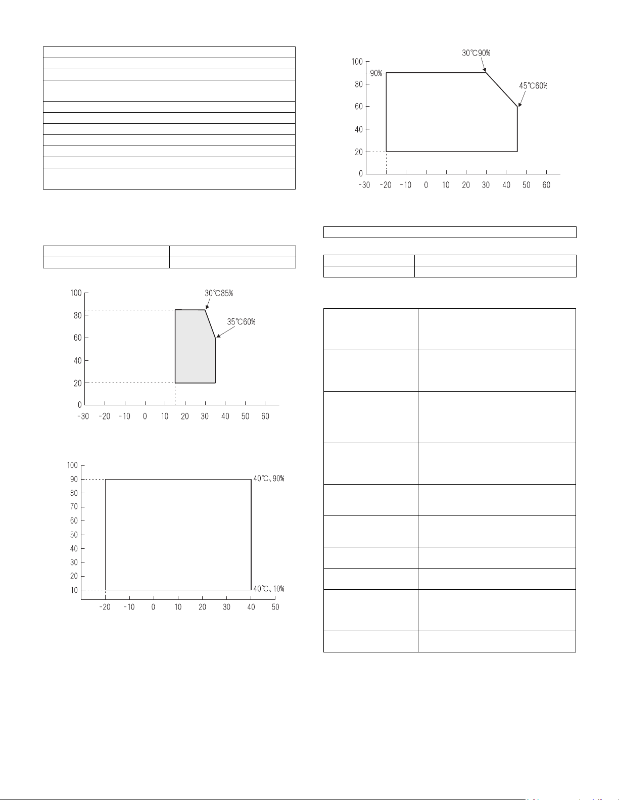
(2) Operating ambient conditions
(3) Ambient storage conditions
(4) Ambient conditions for transporting
(5) Atmospheric pressure
(6) Standard temperature and humidity
7. IMC board functions
Note: The number of sheets for the columns marked with “*” is calcu-
lated supposing that the same quantity is assigned to the ROPM
memory and the copy expansion memory.
International energy program digital complex machine (EPA)
Conforming to New energy star program (2007 new standard)
Environmental Choice Program (ECP)
Conforming to New Blue Angel
* Conforms to 2007 New Blue Angel.
Nordic swan
Conforming to WEEE
European ROHS regulations
ISO11798 (Lightfastness)
ISO19752 (Measures the toner consumption)
Taiwan battery
Other environmental protection standards
(Sharp: Follows the Green Product Declaration.)
Folded multi manual feed 628 (W) × 585.5 (D) mm
Open multi manual feed 894 (W) × 585.5 (D) mm
Temperature (˚C)
Humidity (%)
Temperature (˚C)
Humidity (%)
595 mmHg or above
Temperature 20 to 25°C
Humidity 65±5%RH
* Sort function
(Electronic sort)
32MB (Copy: 16MB, Print: 16MB)
90 sheets (max. 1500 sheets) with A4
standard documents at 600dpi. Offset
paper exit by the shifter function
* Group function 32MB (Copy: 16MB, Print: 16MB)
90 sheets (max. 1500 sheets) with A4
standard documents at 600dpi. Offset
paper exit by the shifter function
Rotation copy
If there is paper of the same size as the
document size, the image is rotated and
printed even though the paper is set in a
different direction. (In some cases,
enlargement rotation may not be executed.)
2 in 1/ 4 in 1 Two pages or four pages of documents are
copied on one page of paper. Division can
be made with slid lines or dotted lines (by
user setup). (The solid line width is 8 lines)
Edge erase Images on the edges of the document are
erased and copy is made. (Adjustable in
the range of 0 – 20mm (0 – 1 inch).)
Center erase The center image of the set document is
erased and copy is made. (Adjustable in
the range of 0 – 20mm (0 – 1 inch).)
Binding edge Binding edge is provided on the left, right
or the top of the set document.
Compression memory
for electronic sort
32MB
* Memory read capacity 32MB (Copy: 16MB, Print: 16MB)
90 sheets (Max. 1500 sheets) of A4
standard documents (Sharp A4 standard
document Test Chart B (6%))
Memory expansion 2 slots for DIMM memory, Max. 512MB x 2
slots + 32MB (Expandable up to 1056MB)
Temperature (˚C)
Humidity (%)
AR-M256/M257/M258/M316/M317/M318/5625/5631 SPECIFICATIONS 3 - 6
8. Printer function
(AR-M256/ M257/ M316/ M317/ 5625/ 5631)
A. “Sharp Printer Language with Compression
(SPLC)” Printer function
(1) Basic specification
B. Printer driver specification
(1) System
(2) Printing function specification
(3) Print quality
* Default
Item Detail
Print Speed 15ppm: 600dpi (including transfer from PC)
25ppm: ROPM (AR-M256/ M257/ 5625)
31ppm: ROPM (AR-M316/ M317/ 5631)
Resolution 600dpi
Smoothing 600dpi
Toner Save Mode Standard
Input tray Multi Bypass tray
Tray 1, Tray 2, Tray 3, Tray 4
(Depending on conditions of the machine
and option installation.)
Duplex print Standard
Finisher Option
Printer driver Standard
Manual
(Online manual)
Standard
Platform IBM PC/ AT (Include compatible machine)
Support OS
(Printer Driver)
Windows 98/ Me
Windows NT 4.0 Workstation (SP5 or later)
Windows 2000
Windows XP/ XP x64
Windows Vista/ Vista x64
Machine OS
IBM PC/ AT (Include
compatible machine)
Windows 98/ Me
Windows NT 4.0 Workstation (SP5 or later)
Windows 2000
Windows XP/ XP x64
Windows Vista/ Vista x64
Function Content
General Copies 1-999
Orientation Portrait
Landscape
Collate Collate
Uncollate
Document Style 1-Sided, 2-Sided (Book),
2-Sided (Tablet)
N-up printing 2/ 4
N-up Order Z
N-up Border Yes/ No
User Setting Yes
Paper Input Paper Size A3/ B4/ A4/ B5/ A5/ B6/ A6/
Ledger (11x17) /
Legal (8.5 x 14) /
Foolscap (8.5 x 13) /
Letter (8.5 x 11) /
Invoice (5.5 x 8.5)/ Folio/
Executive/ COM-10 /
DL/ C5/ 8K/ 16K
Custom Paper Size 1 size
Source Selection • Auto
• Bypass (Auto)
• Bypass (Manual)
• Tray 1/ 2/ 3/ 4
Paper Input
Paper Type Tray:
Normal paper, letter head
paper, recycle paper, colored
paper
Bypass:
Normal paper, recycle paper,
OHP, label paper, gift
wrapping paper, postcards,
double postal card (no folding
line), envelope, postcard
paper, coarse paper, No. 2
master drawing, thick paper
Transparency print Yes/ No
Paper Output
Output Tray Selection • Center Tray
• Upper Tray
• Finisher Offset tray
Staple Yes/ No
Graphic Print Quality Normal
Draft
Photo
Smoothing Yes/ No
Toner save Yes/ No
Photo Enhancement Yes/ No
Fit to Page Yes/ No
2 Gradation print Yes/ No
Image Adjustment Brightness: 0 to 100
Contrast: 0 to 100
Watermark Watermark (None)/ TOP SECRET/
CONFIDENTIAL/ DRAFT/
ORIGINAL/ COPY
User setting Add/ Update/ Delete
Position Center
X: ±50
Y: ±50
Size 6 to 300
Angle ±90
Gray Scale 0 to 255
Edit Font Yes
On first page only Yes/ No
Configuration
Setting
Input Trays Two/ Three/ Four trays
Output Tray Options None/ Upper Tray/ Staple
Finisher
Set Tray Status Yes
Version Information Yes
Others
ROPM Yes/ No
Mode Control Content
Resolution/
Print quality
600dpi
(Fixed)
Print quality is selected from
Normal*/ Draft/ Photo.
Smoothing On* Smoothing function is ON.
Off Smoothing function is OFF.
Toner Save Mode On Toner save function is ON.
Off* Toner save function is OFF.
Photo Enhancement On Photo enhancement function is ON.
Off* Photo enhancement function is
OFF.
2 Gradation print On 2-Gradation print function is ON.
Off* 2-Gradation print function is OFF.
Function Content
AR-M256/M257/M258/M316/M317/M318/5625/5631 SPECIFICATIONS 3 - 7
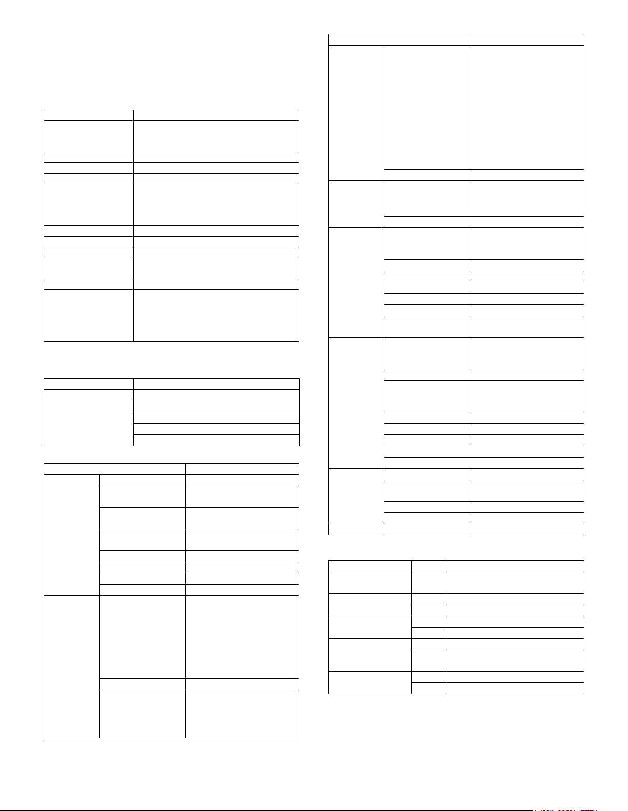
(5) Paper handling specifications
a. Paper feed direction
Limitations on tray/ functions for support paper
(6) Print enable area
Paper name Paper size
Paper feed tray Paper exit tray Function
Manual
tray
Tray 1 Tray 2 Tray 3 Tray 4
Center
tray
Upper
tray
Offset
tray
Staple Fit page
A3 297 x 420 mm Yes Yes Yes Yes Yes Yes Yes Yes Yes Yes
A4 210 x 297 mm Yes Yes Yes Yes Yes Yes Yes Yes Yes Yes
A5 148 x 210 mm Yes Yes N/A N/A N/A Yes Yes N/A N/A Yes
A6 105 x 148 mm Yes N/A N/A N/A N/A Yes N/A N/A N/A Yes
B4 257 x 364 mm Yes Yes Yes Yes Yes Yes Yes Yes Yes Yes
B5 182 x 257 mm Yes Yes Yes Yes Yes Yes Yes Yes Yes Yes
B6 128 x 182 mm Yes N/A N/A N/A N/A Yes Yes N/A N/A Yes
Ledger 11 x 17 inch Yes Yes Yes Yes Yes Yes Yes Yes Yes Yes
Letter 8.5 x 11 inch Yes Yes Yes Yes Yes Yes Yes Yes Yes Yes
Legal 8.5 x 14 inch Yes Yes Yes Yes Yes Yes Yes Yes Yes Yes
Executive 7.25 x 10.5 inch Yes N/A N/A N/A N/A Yes Yes N/A N/A Yes
Folio 8.3 x 13 inch Yes N/A N/A N/A N/A Yes Yes N/A N/A Yes
Invoice 5.5 x 8.5 inch Yes Yes N/A N/A N/A Yes Yes N/A N/A Yes
Foolscap 8.5 x 13 inch Yes Yes Yes Yes Yes Yes Yes Yes Yes Yes
8K 270 x 390 mm Yes Yes Yes Yes Yes Yes Yes Yes N/A Yes
16K 195 x 270 mm Yes Yes Yes Yes Yes Yes Yes Yes N/A Yes
DL 110 x 220 mm Yes N/A N/A N/A N/A Yes Yes N/A N/A Yes
C5 162 x 229 mm Yes N/A N/A N/A N/A Yes Yes N/A N/A Yes
Com10 4.125 x 9.5 inch Yes N/A N/A N/A N/A Yes Yes N/A N/A Yes
Custom W: 100 to 297 mm
L: 148 to 431.8 mm
Yes N/A N/A N/A N/A Yes N/A N/A N/A N/A
Setting direction toward paper
feed port = Long side
Setting direction toward paper
feed port = Short side
Transfer direction
Transfer direction
Actual page size
HP/GL
picture frame
Logic paper size
Print area
Paper
Size
ABCDEFGH
A3 7014 9920 6730 142 100 300 6814 0
B4 6070 8597 5786 142 100 300 5870 0
A4 4960 7014 4676 142 100 300 4760 0
B5 4298 6070 5770 142 100 300 4098 0
A5 3508 4960 3224 142 100 300 3308 0
Ledger 6600 10200 6300 150 100 300 6400 0
Legal 5100 8400 4800 150 100 300 4900 0
Letter 5100 6600 4800 150 100 300 4900 0
Invoice 3300 5100 3000 150 100 300 3100 0
Foolscap 5100 7800 4800 150 100 300 4900 0
Folio 4980 7800 4680 150 100 300 4780 0
Executive 4350 6300 4050 150 100 300 4150 0
COM-10 2474 5700 2174 150 100 300 2274 0
C5 3826 5408 3542 142 100 300 3626 0
DL 2598 5196 2314 142 100 300 2398 0
Actual page
size
HP/GL
picture
frame
Logic paper
size
Print area
AR-M256/M257/M258/M316/M317/M318/5625/5631 SPECIFICATIONS 3 - 8
∗ To p m ar gi n
The set value is received from the digital copier, and data are made
according to the set value.
∗ Left margin
Since the paper size sensor is not set, the digital copier cannot recog-
nize the size and direction of paper which is actually inserted.
Therefore, the left margin is set according to the paper size specified in
the print data sent from the computer, and print process is performed.
If the computer does not specify the paper size, or in the case of the
custom size, the left margin is set according to the default paper size.
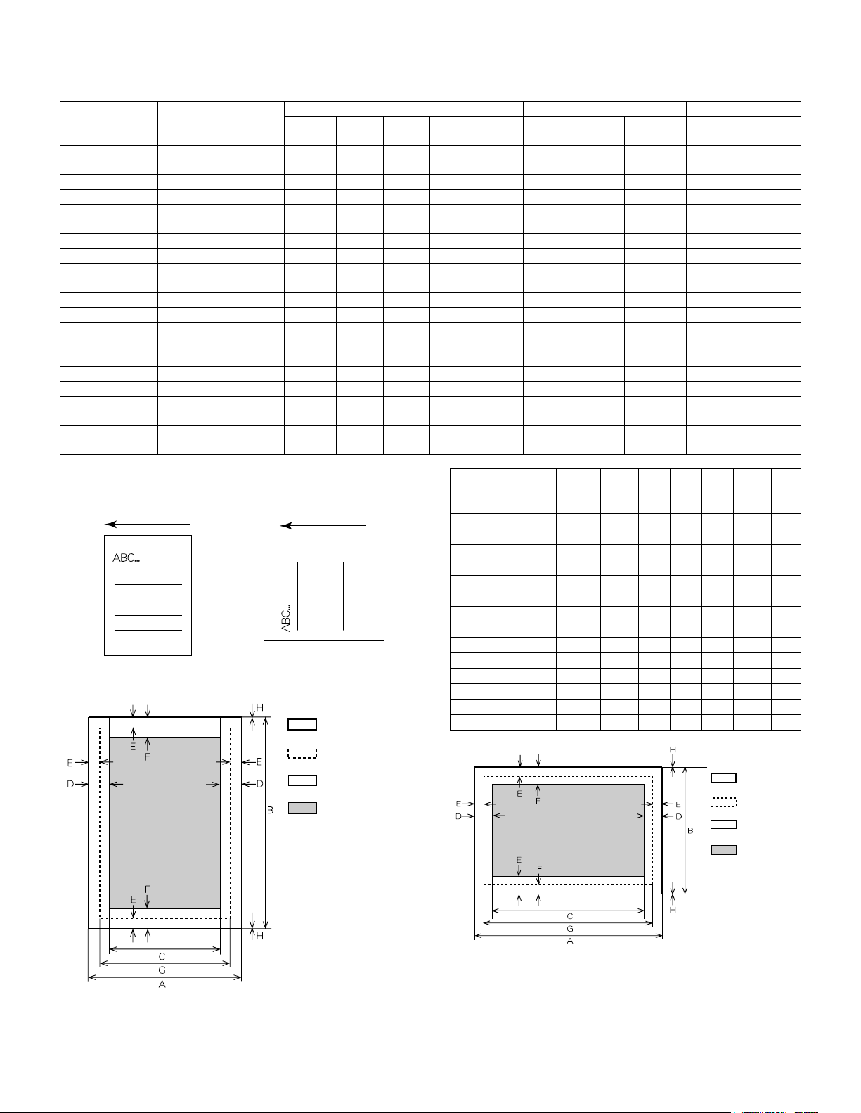
(7) Print reference
This machine employs the center reference system.
Since the digital copier is not provided with the tray size detection fea-
ture, formatting and center distribution are performed not by the actual
paper size but by the paper size specified by the computer.
C. Interface
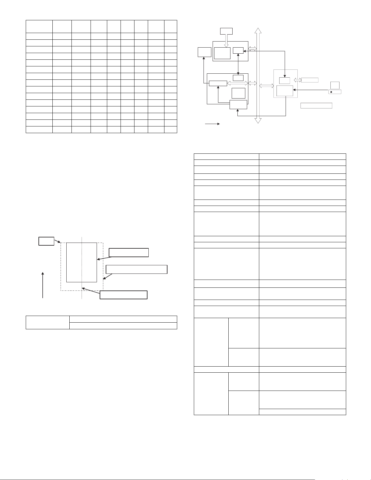
D. System outline
The GDI-PWB is provided with IEEE1284 I/F on the host side, and the
16-bit bi-directional data bus I/F and UART on the machine side. Trans-
fer of image data with the IMC-PWB is performed with this 16-bit bi-
directional data bus. Command status information with the engine is
processed with UART.
This unit is installed to the position of PCL-PWB on the conventional
AR-235/ 275.
JBIG compression data sent from the host are transferred to the IMC
PWB, where the data are extracted to be VIDEO data, and sent
through the MCU PWB to the LSU.
9. Printer function (AR-M258/ M318)
A. Basic function
*1: The network scan requires 1 slot of memory (max. 256MB). When,
therefore, the network scan is installed, the maximum memory area
available for the printer functions is 320MB.
*2: PDF print is available with PostScript.
Paper
Size
ABCDEFGH
A3 9920 7014 9684 118 100 300 9720 0
B4 8597 6070 8361 118 100 300 8397 0
A4 7014 4960 6778 118 100 300 6814 0
B5 6070 4298 5830 118 100 300 5870 0
A5 4960 3508 4720 118 100 300 4760 0
Ledger 8400 5100 8160 120 100 300 8200 0
Legal 8400 5100 8160 120 100 300 8200 0
Letter 6600 5100 6360 120 100 300 6400 0
Invoice 5100 3300 2860 120 100 300 4900 0
Foolscap 7800 5100 7560 120 100 300 7600 0
Folio 7800 4980 7560 120 100 300 7600 0
Executive 6300 4350 6060 120 100 300 6100 0
COM-10 5700 2474 3460 120 100 300 5500 0
C5 5408 3826 5172 118 100 300 5208 0
DL 5196 2598 4960 118 100 300 4996 0
Interface IEEE 1284 (Parallel interface)
USB Ver. 2.0
ABCDEFGHIJKLMN
12345
abc
Origin
Paper feed direction
Center reference line
Size specified by the HOST
Actual paper size
Item Detail
Print Speed 600dpi
Resolution 300dpi, 600dpi
Smoothing 600dpi
Standard memory 64 MB (Standard) +256MB x 1
Expansion memory
*1
DIMM 1 slot
144 pin 256MB DIMM
Optional memory 8MB flash DIMM
Toner save mode
Standard
Paper feed tray Multi manual feed tray
Tray1, Tray2, Tray3, Tray4
(Depends on the installation status of
the machine and options.)
Duplex print Standard
Finisher Option
NIC Standard (AR-P27)
• 10Base-T, 100Base-TX
• Corresponding protocol:
IP/ SPX, TCP/ IP, IPV6, Comforming
to IPsec, EtherTalk, NetBEUI
PostScript Level3
*2
Option
Packed software Printer driver, PAU4.0, Status monitor,
Installer
Operation manual Standard (Online manual)
Platform IBM PC/ AT compatible machine
Macintosh
Support OS
(Printer
driver)
Custom PS/
PPD/
Custom
PCL5e/ 6
Windows 98/ Me
Windows NT 4.0 (SP5 or later)
Windows 2000/ Server 2003
Windows XP/ XP x64
Windows Vista/ Vista x64
Only PPD MacOS 9.0 to 9.2.2/ X10.1.5/ X10.2.8
MacOS 10.3.3 to 10.3.9/ X10.4/
X10.4.4
Support PDL PCL5e, PCL6, PostScript Level 3,
Installed fonts Standard PCL5e/PCL6:
Roman outline fonts = 80 types
Line printer font (Bitmap) = 1 type
Option PCL5e/PCL6:
Bar code fonts = 28 types (Can be
provided by the flash ROM kit as well)
PS3: Roman outline fonts = 136 types
CCD
M-bus
CPU
CPU
CPU
PC
GDI
JBIG
data
ASIC
JBIG-
Lite
IMC
MCU
Print
Engine
Image
process
ASIC
UART
Command status
Header + JBIG data
IEEE1284
JBIG printer driver
Compressed
memory
Extraction
Data through
: Data flow
Page memory
AR-M256/M257/M258/M316/M317/M318/5625/5631 CONSUMABLE PARTS 4 - 1
[4] CONSUMABLE PARTS
1. Supply system table
A. SEC/ SECL/ LAG
B. Europe/ East Europe/ Russia / Australia/ New Zealand
C. Asia affiliates
D. SMEF/ Israel/ Philippines/ Agent
E. Taiwan
F. Hong Kong
G. China
No. Item Content Life Model name Remarks
1 Toner cartridge
(black)
Toner cartridge (With IC chip)
(Toner; Net weight 745g)
TNCA replacement operation manual
×10
×10
25K (×10) AR-310MT Life setting by A4 (8.5"×11") 6% document
MT=NT*10
2 Developer (black) Developer
(Developer; Net weight 400g)
×10 25cpm: 75K (×10)
31cpm: 100K (×10)
AR-271MD MD=ND*10
3 Drum Drum ×1 25cpm: 75K
31cpm: 100K
AR-310DR
No. Item Content Life Model name Remarks
1 Toner cartridge
(black)
Toner cartridge (With IC chip)
(Toner; Net weight 745g)
TNCA replacement operation manual
×10
×10
25K (×10) AR-310LT Life setting by A4 (8.5"×11") 6% document
LT =T *1 0
2 Developer (black) Developer
(Developer; Net weight 400g)
×10 75K (×10) AR-271LD LD=DV*10
3 Drum Drum ×1 75K AR-310DM
No. Item Content Life Model name Remarks
1 Toner cartridge
(black)
Toner cartridge (With IC chip)
(Toner; Net weight 745g)
TNCA replacement operation manual
×10
×10
25K (×10) AR-310CT Life setting by A4 (8.5"×11") 6% document
CT=ST*10
2 Developer (black) Developer
(Developer; Net weight 400g)
×10 75K (×10) AR-271CD CD=SD*10
3 Drum Drum ×1 75K AR-310DR
No. Item Content Life Model name Remarks
1 Toner cartridge
(black)
Toner cartridge (With IC chip)
(Toner; Net weight 745g)
TNCA replacement operation manual
×10
×10
25K (×10) AR-310ET Life setting by A4 (8.5"×11") 6% document
ET=FT*10
2 Developer (black) Developer
(Developer; Net weight 400g)
×10 75K (×10) AR-271LD LD=DV*10
3 Drum Drum ×1 75K AR-310DR-T
No. Item Content Life Model name Remarks
1 Toner cartridge
(black)
Toner cartridge (With IC chip)
(Toner; Net weight 745g)
TNCA replacement operation manual
×10
×10
25K (×10) AR-310CT-C Life setting by A4 (8.5"×11") 6% document
CT-C=ST-C*10
2 Developer (black) Developer
(Developer; Net weight 400g)
×10 75K (×10) AR-271CD-C CD-C=SD-C*10
3 Drum Drum ×1 75K AR-310DR-C
No. Item Content Life Model name Remarks
1 Toner cartridge
(black)
Toner cartridge (With IC chip)
(Toner; Net weight 455g)
TNCA replacement operation manual
×1
×1
15K (×10) AR-311ST-C Life setting by A4 (8.5"×11") 6% document
* Without toner save.
2 Developer (black) Developer
(Developer; Net weight 400g)
×1 75K (×10) AR-271SD-C
3 Drum Drum ×1 75K AR-310DR-C

AR-M256/M257/M258/M316/M317/M318/5625/5631 CONSUMABLE PARTS 4 - 2
2. Maintenance parts list
A. SDSCA/ SECL/ LAG (AR-M257/ M317)
∗ The other maintenance parts than the above are supplied as service parts.
B. SEEG/ SUK/ SCA/ SCNZ/ SEA/ SEES/ SEZ/ SEIS/ SEB/ SEN/ SEF/ SMEF/ Russia/ Special country
(AR-M256/ M316, AR-5625/ 5631)
∗ The other maintenance parts than the above are supplied as service parts.
No. Item Content Life
Model
name
Remarks
1 Upper heat roller kit Upper heat roller
Fuser gear
Upper heat roller bearing
Upper cleaning pad
Fusing separation pawl (upper)
×1
×1
×2
×1
×4
150K AR-310UH
2 Lower heat roller kit Lower heat roller
Fusing separation pawl (lower)
Fuser bearing (lower)
×1
×4
×2
300K AR-310LH
3 150K maintenance
kit
Drum separation pawl unit
Transfer roller unit
×2
×1
150K AR-310KA1
4 MC unit MC unit ×10 25cpm: 75K (×10)
31cpm: 100K (×10)
AR-310MC AR-310MC = AR-310NC ×10
The order places an order in AR-310MC.
Addition of Sterling.
5 Cleaner blade Cleaner blade ×10 25cpm: 75K (×10)
31cpm: 100K (×10)
AR-270CB AR-270CB = AR-270BL ×10
The order places an order in AR-270CB.
6 Drum frame unit Drum frame unit ×1 25cpm: 225K
31cpm: 300K
AR-310DU
∗ The life of the toner reception seat attached to
the drum frame is 225K (25cpm)/ 300K
(31cpm), and it can be used up to 3 times.
(Supplied as a drum frame unit.)
∗ Drum frame unit contains all the drum unit
parts excluding Drum and Drum fixing plate.
7 Transfer roller unit Transfer roller unit ×1 150K AR-310TX
8 Paper feed roller kit Paper feed roller kit ×1 100K AR-310IR
9 Fusing unit Fusing unit (120V heater lamp) ×1 150K AR-310FU
10 Staple cartridge Staple cartridge ×3 3000 staples ×3 AR-SC1 For AR-FN5A (For 30 sheets staple)
Common with the cartridge for FN4
11 Staple cartridge Staple cartridge ×3 5000 staples ×3 AR-SC2 For AR-F14N (For 50 sheets staple)
Common with the cartridge for FN7
No. Item Content Life
Model
name
Remarks
1 Upper heat roller kit Upper heat roller
Fuser gear
Upper heat roller bearing
Upper cleaning pad
Fusing separation pawl (upper)
×1
×1
×2
×1
×4
150K AR-310UH
2 Lower heat roller kit Lower heat roller
Fusing separation pawl (lower)
Fuser bearing (lower)
×1
×4
×2
300K AR-310LH
3 150K maintenance
kit
Drum separation pawl unit
Transfer roller unit
DV blade
DV side sheet N
×2
×1
×1
×2
150K AR-310KA
4 MC unit MC unit ×10 25cpm: 75K (×10)
31cpm: 100K (×10)
AR-310MC AR-310MC = AR-310NC ×10
The order places an order in AR-310MC.
Addition of Sterling.
5 Cleaner blade Cleaner blade ×10 25cpm: 75K (×10)
31cpm: 100K (×10)
AR-270CB AR-270CB = AR-270BL ×10
The order places an order in AR-270CB.
6 Drum frame unit Drum frame unit ×1 25cpm: 225K
31cpm: 300K
AR-310DU
∗ The life of the toner reception seat attached to
the drum frame is 225K (25cpm)/ 300K
(31cpm), and it can be used up to 3 times.
(Supplied as a drum frame unit.)
∗ Drum frame unit contains all the drum unit
parts excluding Drum and Drum fixing plate.
7 Transfer roller unit Transfer roller unit ×1 150K AR-310TX
8 Staple car tridge Staple cartridge ×3 3000 staples ×3 AR-SC1 For AR-FN5A (For 30 sheets staple)
Common with the cartridge for FN4
9 Staple cartridge Staple cartridge ×3 5000 staples ×3 AR-SC2 For AR-F14N (For 50 sheets staple)
Common with the cartridge for FN7

AR-M256/M257/M258/M316/M317/M318/5625/5631 CONSUMABLE PARTS 4 - 3
C. STCL/ SRH/ SRS/ SRSSC/ SBI/ Agent (All model)
∗ The other maintenance parts than the above are supplied as service parts.
No. Item Content Life
Model
name
Remarks
1 Upper heat roller kit Upper heat roller
Fuser gear
Upper heat roller bearing
Upper cleaning pad
Fusing separation pawl (upper)
×1
×1
×2
×1
×4
150K AR-310UH
2 Lower heat roller kit Lower heat roller
Fusing separation pawl (lower)
Fuser bearing (lower)
×1
×4
×2
300K AR-310LH
3 150K maintenance
kit
Drum separation pawl unit
Transfer roller unit
DV blade
DV side sheet N
×2
×1
×1
×2
150K AR-310KA
4 MC unit MC unit ×10 25cpm: 75K (×10)
31cpm: 100K (×10)
AR-310MC AR-310MC = AR-310NC ×10
The order places an order in AR-310MC.
Addition of Sterling.
5 Cleaner blade Cleaner blade ×10 25cpm: 75K (×10)
31cpm: 100K (×10)
AR-270CB AR-270CB = AR-270BL ×10
The order places an order in AR-270CB.
6 Drum frame unit Drum frame unit ×1 25cpm: 225K
31cpm: 300K
AR-310DU
∗ The life of the toner reception seat attached to
the drum frame is 225K (25cpm)/ 300K
(31cpm), and it can be used up to 3 times.
(Supplied as a drum frame unit.)
∗ Drum frame unit contains all the drum unit
parts excluding Drum and Drum fixing plate.
4 Staple car tridge Staple cartridge ×3 3000 staples ×3 AR-SC1 For AR-FN5A (For 30 sheets staple)
Common with the cartridge for FN4
5 Staple cartridge Staple cartridge ×3 5000 staples ×3 AR-SC2 For AR-F14N (For 50 sheets staple)
Common with the cartridge for FN7
AR-M256/M257/M258/M316/M317/M318/5625/5631 CONSUMABLE PARTS 4 - 4
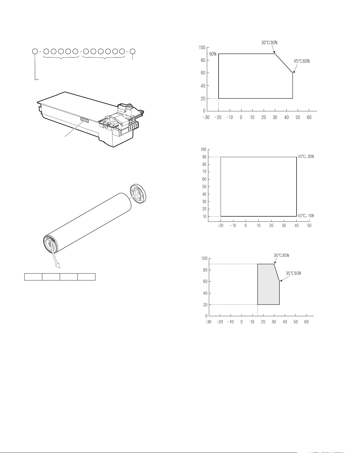
2. Production number identification
<TD cartridge>
The label on the TD cartridge shows the date of production.
<Drum>
The laser print indicates the date (year, month, day) of production.
1 The last digit of the production year.
2 The production month.
X stands for October, Y November, and Z December.
3, 4The production day.
3. Environment conditions
A. Ambient conditions for transporting
B. Ambient storage conditions (sealed)
C. Operating ambient conditions
4. Life (packed conditions)
Photoconductor drum (36 months from the production month)
Developer, toner (24 months from the production month)
1234
Label position
Serial number
(0001-9999)
Version no.
Date of oroduction
location of manufacture
Temperature (˚C)
Humidity (%)
Temperature (˚C)
Humidity (%)
Use envi-
ronment
conditions
Humidity (%)
Temperature (˚C)
AR-M256/M257/M258/M316/M317/M318/5625/5631 UNPACKING AND INSTALLATION 5 - 1
[5] UNPACKING AND INSTALLATION
1. Installation
A. Environment
The performance of this machine is affected by the environment of the
installing site. Avoid installation to the following places:
• Avoid installation in direct sunlight, otherwise the plastic parts may
be deformed.
• Avoid installation in a place of high temperature, high humidity, low
temperature or low humidity, otherwise paper may be dampened and
frost may be generated in the machine to cause a paper jam and
dirty copy.
• Avoid installation in a dusty place, otherwise dust may enter the
machine to cause dirty copy or machine troubles.
• Avoid installation to a place with much vibration, otherwise the
machine may cause troubles.
• Avoid installation to a place of poor ventilation.
• Avoid installation to a place where there is ammonium gas.
Installation near a diazo-copier may lead to dirty copy.
• Be sure to have enough space around the machine.
Be sure to allow the required space around the machine for servicing
and proper ventilation.
B. Power source
• Be sure to use only the power outlet (with the earth terminal) of 15A
or more and 100V.
• Install the machine near the power outlet to facilitate disconnection
of the power plug.
• If the power plug of this machine and other illuminating apparatus
are connected to the same power outlet, the lamp may flicker. Use
an exclusive power outlet for this machine without connecting
another lamp together.
• Avoid complex wiring. Be careful not to damage, break, or process
the power cord.
• Earth wire connection
Be sure to connect the earth wire for protection against danger.
If not, improper grounding may cause a fire or an electric shock.
C. Transport
• When transporting the machine, use two people to lift the machine
using the two grips provided on each side of the machine.
12" (30cm)
12"
(30cm)
12"
(30cm)
Earth terminal
AR-M256/M257/M258/M316/M317/M318/5625/5631 UNPACKING AND INSTALLATION 5 - 2
D. Other precautions
• If the machine produces smoke or bad smell, stop the operation of
the machine.
• Do not use flammable spray near the machine.
• Do not remove the cabinet of the machine.
• Do not put a receptacle with water in it or metal pieces, which may
drop inside the machine, causing a trouble.
• When it thunders, turn off the power and disconnect the power plug
from the power outlet to prevent against an electric shock or a fire
caused by lighting damage.
• If a piece of metal or water enters the machine, turn off the power
and disconnect the power plug from the power outlet.
• Do not touch the power plug with a wet hand.
• Do not remodel the machine.
• Be careful not to pinch your fingers when closing the front cover or
the side cover and setting the paper feed tray to supply paper or pro-
cess a paper jam.
• When disconnecting the power plug from the power outlet, do not
pull the cord.
• Do not throw toner or the toner cartridge into a fire.
• Keep toner or the toner cartridge away from the children.
• When the exclusive table (option) is used, be sure to use the adjust-
ers (4 pcs.) on the floor.
When it is required to move the machine for rearrangement of the
office, etc., release the adjuster locks and move the machine.
• The fusing section is heated to a high temperature.
When removing a paper jam, be careful not to touch the fusing sec-
tion.
• When the machine is not used for a long time, disconnect the power
plug from the power outlet for safety.
• When transporting the machine, turn off the power and disconnect
the power plug from the power outlet. (Remove the earth wire after
disconnecting the power plug from the power outlet.)
2. Removal of protective material and fixing
screw
1) Remove all tapes, then open the document cover and remove the
protective material of sheet shape.
2) Use a screwdriver to remove the fixing screw.
The fixing screw is required when transporting the machine. Keep
it in the tray. (Refer to the later description.)
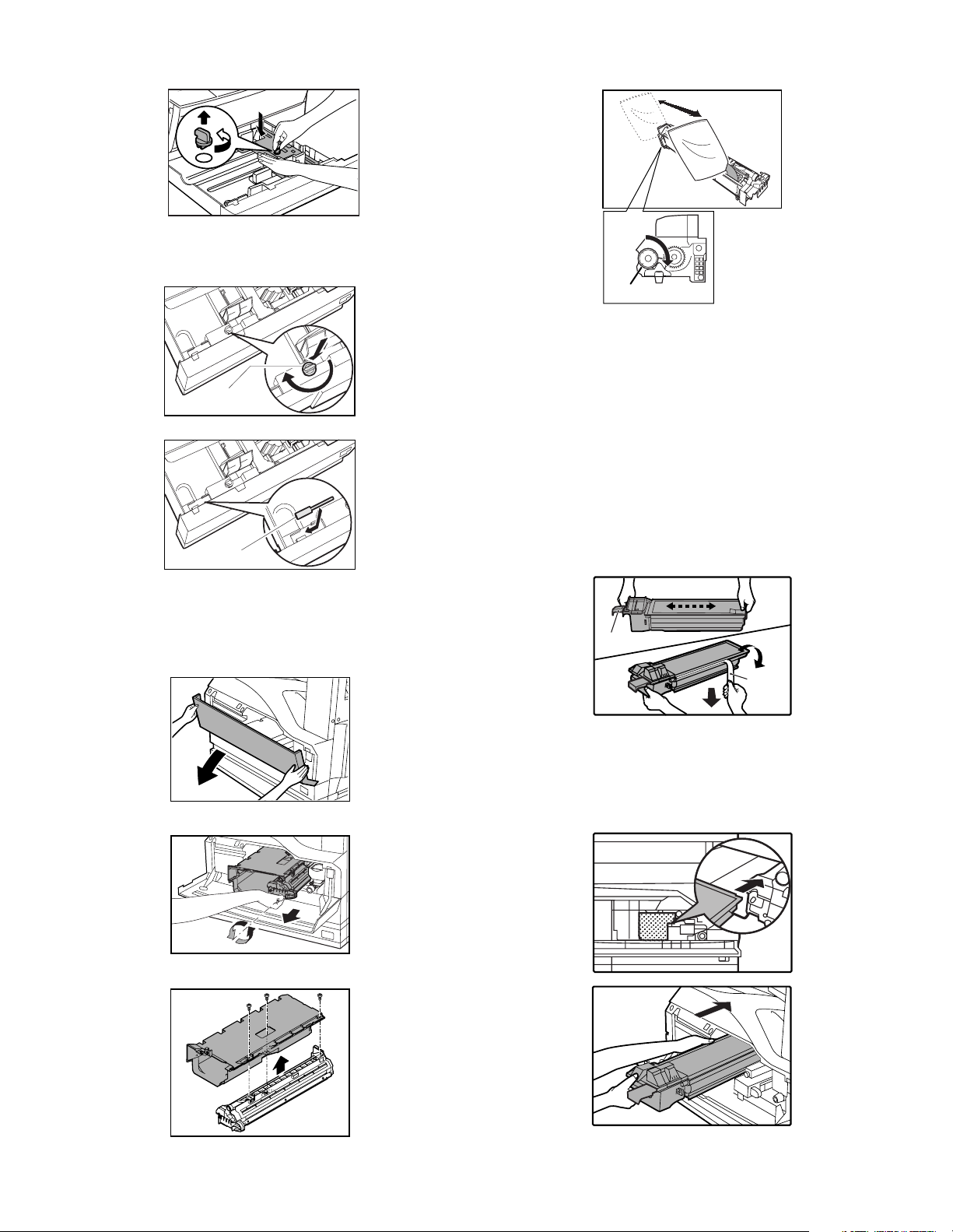
3. Removal and storage of fixing pin
1) Lift the knob and gently pull out the tray.
Lock
Adjuster
Release
Fusing section
AR-M256/M257/M258/M316/M317/M318/5625/5631 UNPACKING AND INSTALLATION 5 - 3
2) Hold the paper pressure plate and turn the fixing pin in the arrow
direction.
3) Store the removed fixing pin and the fixing screw which was
removed in the above procedure, together in the specified storage
place in the tray.
∗ If power is turned don without removing the fixing pin, it will be diffi-
cult to pull out the tray.
4. Developer cartridge installation
1) Hold the both sides of the front cover, and pull down to open it.
2) Loosen the blue screw and pull out the developing cartridge.
3) Remove the developer tank from the developer cartridge.
4) Rotate the MG roller in the arrow direction and supply developer
evenly into the developing unit.
∗ Shake the developer bag well before opening it.
∗ Check that the DV seal is free from developer. If developer is
attached to the DV seal, clean and remove it.
5) Attach the developer tank to the developer cartridge.
After supplying developer into the developer cartridge, do not tilt or
shake the developer cartridge.
6) Attach the developer cartridge to the copier, and fix it with the
screw.
Note: When replacing the OPC drum with a new one, be sure to clear
the drum count.
5. Toner cartridge installation
1) Remove the toner cartridge from the bag, shake it about 20 times
horizontally, and remove the tape.
∗ When holding the toner cartridge, do not touch the shutter section,
but hold the grips. Do not remove the tape before shaking the car-
tridge.
2) Press the lock release lever, and insert the unit completely into the
copier along the guide groove. Then fix the blue screw and the
locking screw.
∗ Dir t or dust must be removed from the toner cartridge before
installing.
Fixing pin
Fixing screw
MG roller
Tape
Shutter
Shake about 20 times.
AR-M256/M257/M258/M316/M317/M318/5625/5631 UNPACKING AND INSTALLATION 5 - 4
3) Remove the tape from the shutter, and remove the shutter from the
toner cartridge.
Dispose the removed shutter.
6. Toner density sensor level adjustment
1) Open the cover with the power OFF.
2) Power ON (The mechanism cannot be initialized because the
cover is open.)
3) Install the developing unit with new developer in it.
4) Enter SIM 25-2.
(# →∗→C →∗→25 → START → 2 → START)
5) Close the cover immediately before starting the operation.
6) Press the [START] key to start.
After completion of the adjustment, be sure to cancel the simulation.
Note: When replacing developer with new one, be sure to clear the
developer counter.
7. Tray paper size setting
When you change the paper in a tray, follow the steps below to change
the tray's paper type and paper size settings.
The settings cannot be changed when operation has stopped because
the paper ran out or a misfeed occurred, or when an interrupt copy job
is being performed.
Even in copy mode, the settings cannot be changed while a print job or
received fax is being printed.
Note:
• 5-1/2" x 8-1/2" (A5) size paper can only be set for tray 1.
• B5 size paper cannot be set for tray 2 (However, B5R size paper can
be set.).
• Tray settings for trays other than the bypass tray can be prohibited in
the key operator programs.
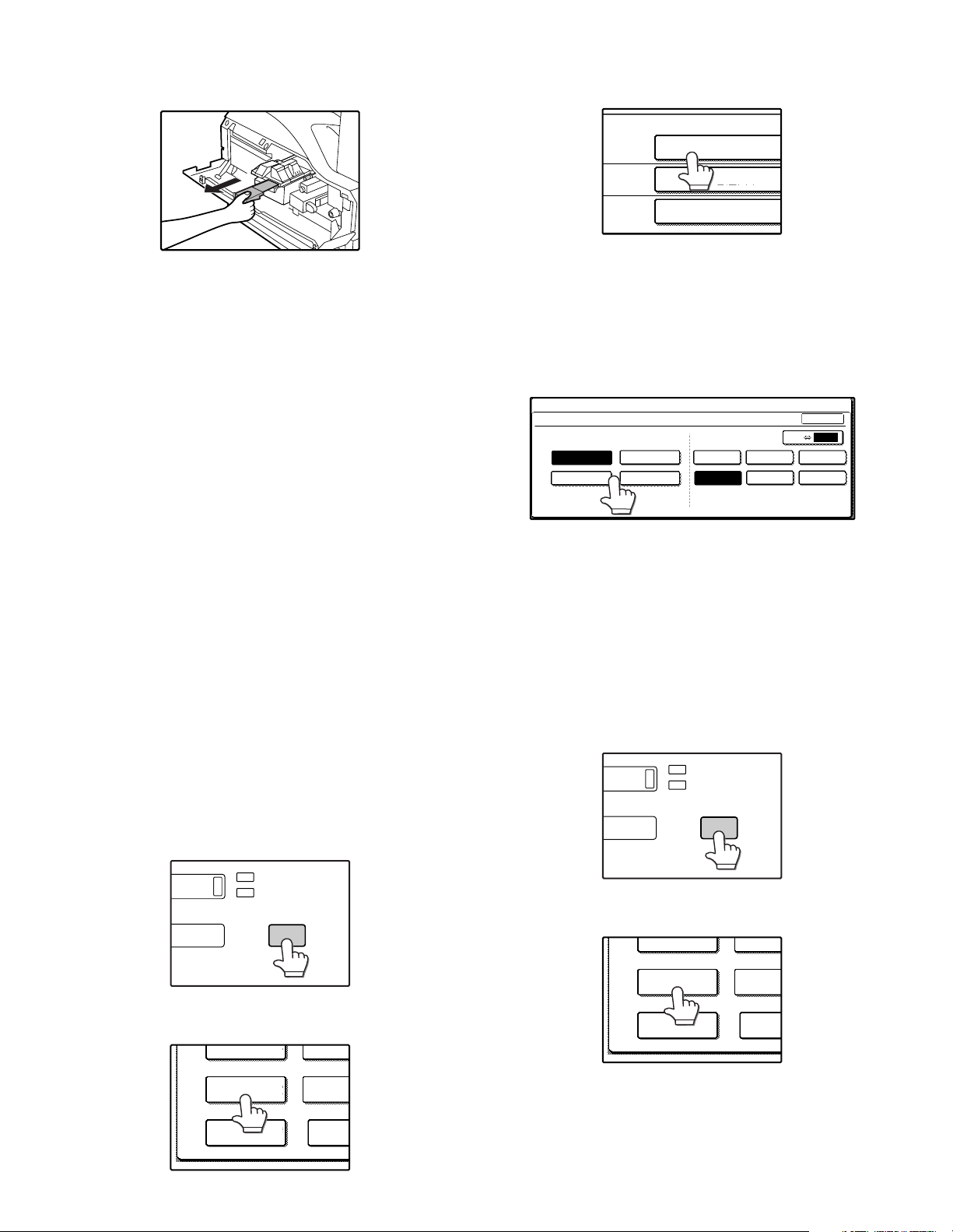
A. Trays 1 – 4
1) Set paper on the tray.
2) Press the [CUSTOM SETTINGS] key.
The custom settings menu screen will appear.
3) Touch the [TRAY SETTINGS] key.
The tray settings screen will appear.
4) Select the tray in which you loaded paper.
If the desired tray does not appear in the display, use the [↑] key or
[↓] key to scroll until it appears.
5) Select the size and type of paper that is loaded in the tray.
The currently selected paper type will be highlighted.
• To change the paper type selection, touch the appropriate type
key.
• To change the paper size selection, touch the appropriate size
key.
• To change the displayed size selections to AB sizes, touch [AB
↔ INCH].
6) Touch the [OK] key.
7) A message appears prompting you to check the paper in the tray.
Check the paper and then touch the [OK] key.
You will return to the tray settings screen.
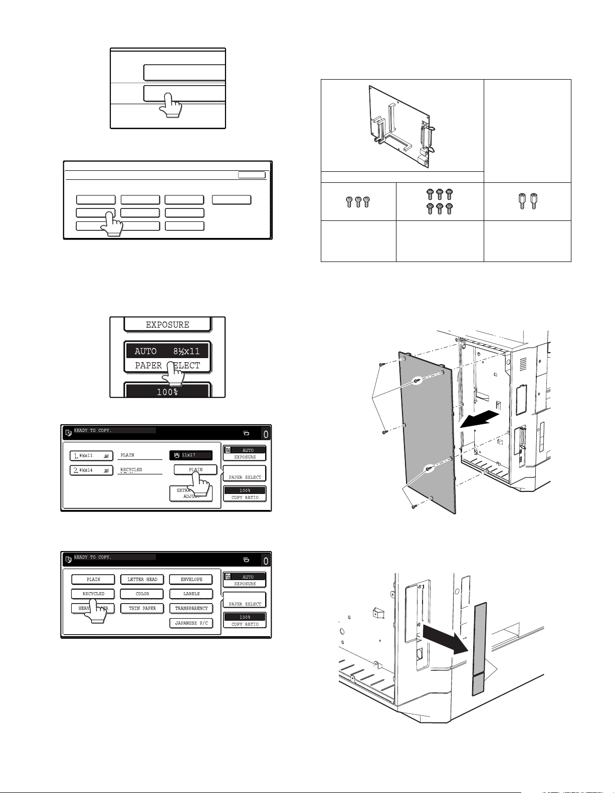
B. Manual feed tray
Use either of the following two methods to set the bypass tray's paper
type setting.
(1) From the [CUSTOM SETTINGS] key
1) Set paper on the tray.
2) Press the [CUSTOM SETTINGS] key.
The custom settings menu screen will appear.
3) Touch the [TRAY SETTINGS] key.
The tray settings screen will appear.
DATA
LINE
CUSTOM SETTINGS
TOT L COUNT
TRAY SETTINGS
ADDRE
CONTRO
KEYBOARD
SELECT
KEY
CONTRA
TRAY 1
TRAY 2
TRAY 3
PLAIN / 8½ x 14
PLAIN / 11x17
TYPE / SIZE
PLAIN / 8½ x 11
CUSTOM SETTINGS
TRAY 1 TYPE/SIZE SETTING
TYPE
RECYCLED
PLAIN
COLOR
LETTER HEAD 11x17
8½x11
8½x14
8½x11R 5½x8½
8½x13
OK
SIZE AB INCH
DATA
LINE
CUSTOM SETTINGS
TOT L COUNT
TRAY SETTINGS
ADDRE
CONTRO
KEYBOARD
SELECT
KEY
CONTRA
AR-M256/M257/M258/M316/M317/M318/5625/5631 UNPACKING AND INSTALLATION 5 - 5
4) Touch the [BYPASS TRAY] key.
5) Select the type of paper that is loaded in the tray.
"JAPANESE P/C" refers to official postcards used in Japan.
6) Touch the [OK] key.
You will return to the tray settings screen.
(2) From the [PAPER SELECT] key
1) Set paper on the tray.
2) Touch the [PAPER SELECT] key.
3) Touch the paper type selection key.
4) Select the paper type.
"JAPANESE P/C" refers to official postcards used in Japan.
5) Touch the [PAPER SELECT] key.
You will return to the main screen of copy mode.
8. Installation of options
A. AR-P27
(1) Parts included
(2) Installation procedure
Turn off the main switch of the copier and then remove the power
plug of the copier from the outlet.
1) Remove the shielding plate.
Remove five screws and remove the shielding plate.
2) Cut and remove the cut-out portion from the left rear cabinet.
Cut and remove the cut-out portion of the left rear cabinet using a
tool such as diagonal cutters. (Be careful about the direction of the
tool so that the cut surface is flat)
TRAY 4
BYPASS
TRAY
TYPE / SIZE
PLAIN
PLAIN / 11x17
CUSTOM SETTINGS
BYPASS TRAY TYPE SETTING
SELECT THE PAPER TYPE.
RECYCLED
PLAIN
COLOR
HEAVY PAPER THIN PAPER
LETTER HEAD
LABELS
TRANSPARENCY
ENVELOPE JAPANESE P/C
OK
CD-ROM: 1 pc.
Operation manual
Installation caution
sheet
PCL PWB: 1 pc.
M3 screws: 3 pcs.
(For installation of
the parallel and the
USB connectors)
M3 screws with
spring washer : 6 pcs.
(For installation of the
PCL PWB)
Support post : 2 pcs.
Screws
Screws
Cut-out portion
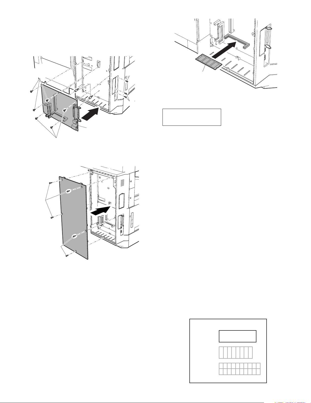
AR-M256/M257/M258/M316/M317/M318/5625/5631 UNPACKING AND INSTALLATION 5 - 6
3) Attach the PCL PWB unit.
Attach the support post to the mounting plate of machine options.
Then connect the PCL PWB connector to the mother board con-
nector and fit the PCL PWB with the six screws with M3 spring
washer (packed with the unit).
Then, attach the parallel and USB connector portion using the sup-
plied three screws.
4) Attach the shielding plate.
Attach the shielding plate using five screws.
Insert the power plug of the copier to the outlet and turn on the
main switch. Then, carry out the following procedure.
5) Check for the PCL PWB.
Press the PRINT key on the operation panel to check to see if the
copier enters the print mode.
6) Check for the language.
Check for the language setting (26-22) following the procedure
described in the service manual (section of simulation).
7) Check for printing.
For installation of printer drivers on a computer, see the supplied
operation manual.
Then, connect a parallel cable to the computer and execute print-
ing to check to see if printing can be executed properly.
(3) Mounting of additional memory
(After mounting it, Installation proceed to step 4.)
Insert the memory module until it clicks.
The memory module is lock when it is inserted. However, be sure to
check that the module slit is engaged with the connector rib when it is
inserted.
B. AR-PK1N
(1) Parts included
*NOTE: Do not use the CD-ROM packed in AR-PK1N, but use the CD-
ROM packed together with the AR-P27 for setting the PS
driver.
(2) Installation procedure
To enable the PS3, the product key must be acquired.
(For the method of acquiring the product key, contact the SHARP
authorized dealer.)
1) Check that AR-P27 operates normally.
• Turn on the power and wait until warming up is complete.
• Press the PRINT key on the operation panel of the main unit.
• If the LCD in the operation panel of the main unit switches to the
print mode normally, AR-P27 is operating normally.
• If it is not operating normally, follow the AR-P27 Installation Man-
ual to check and modify the system configuration settings and
check the operation.
2) Enable the PS3.
To enable the system configuration, use the keys on the main unit
to set the mode.
Enter the product key with the key operator program. (Refer to the
Operation Manual of Key Operator Program.)
Setting of the product key is complete. To update the system, press
the CA key to exit the setting mode.
3) Check the PS3.
Make the following sequence of selections on the control panel.
• Press Special Functions , highlight Configuration and press OK.
• Use the up and down keys to highlight Test print menu and press
OK.
• Use the up/down keys to highlight Configuration page and press OK.
A configuration page will be printed.
Check that the option memory capacity is 128 MB or more.
Check that the PS3 has been installed.
Support
post
PCL PWB
M3 screws with
spring washer
M3 screw
M3 screws
M3 screws with
spring washer
Screws
Screws
CD-ROM: 1*
License agreement
Installation caution sheet
Memory module
(S.O.DIMM)
APPLICATION
NUMBER
MACHINE
SERIAL
NUMBER
PRODUCT
KEY
Please keep below important information.
This information will use for other products.
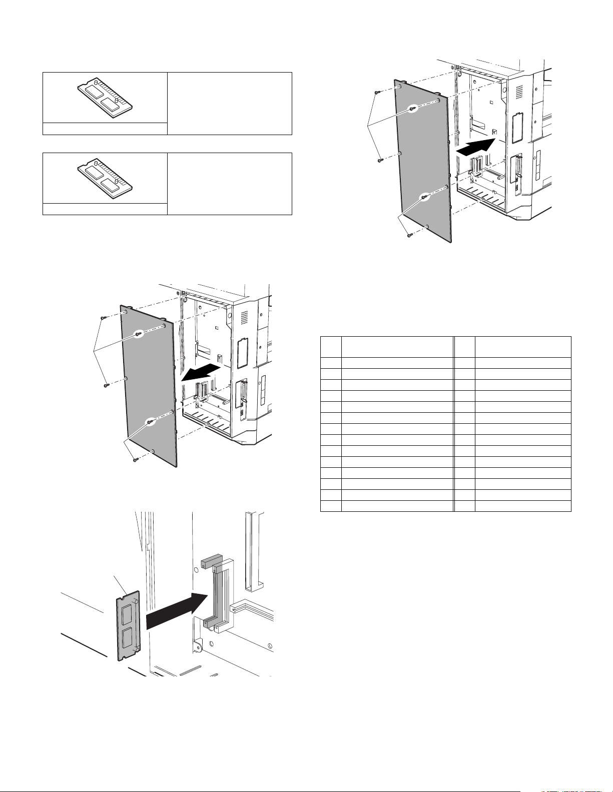
AR-M256/M257/M258/M316/M317/M318/5625/5631 UNPACKING AND INSTALLATION 5 - 7
C. AR-PF1/PF2
(1) Parts included
AR-PF1
AR-PF2
(2) Installation
Turn off the main switch of the copier and then remove the power
plug of the copier from the outlet.
1) Remove the shielding plate.
Remove five screws and remove the shielding plate.
2) Attach the bar code board/flash ROM.
Attach the bar code board/flash ROM board to CN7 of the printer
board.
3) Attach the shielding plate.
Attach the shielding plate using the five screws.
Insert the power plug of the copier to the outlet and turn on the
main switch. Then, carry out the following procedure.
4) Check the bar codes. (AR-PF1 only)
Use the operation keys on the operation panel to print the PCL font
list from the test page printing.
Check that the optional font list is printed at the end.
(3) Font list
(4) Check when installing the AR-PF2
Check can be made by print out of the printer setting list.
The expansion font item in the printer setting list is changed from "unin-
stalled" to "download font."
D. MX-NSX1
(1) Packed items
This network scanner kit includes the following items in the package.
• CD-ROM (Network Scanner Tool and Sharpdesk, Installer, Sharp
TWAIN driver, etc.)
• Installation caution sheet and Operation Manual (License numbers
of 10 user clients of Sharpdesk are specified.)
(2) Installation procedure
To use the scanner expansion kit, a S.O.DIMM memory module (128
MB or more) is needed.
If no memory is added, an S.O.DIMM module must be mounted on
PCL PWB.
For the mounting method and the memory capacity, see below.
To enable the scanner function, the product key must be acquired.
(For the method of acquiring the product key, contact the SHARP
authorized dealer.)
CD-ROM: 1 pc.
Operation manual
Installation caution sheet
Bar code board: 1 pc.
Operation manual
Installation caution sheet
Flash ROM board: 1 pc.
Screws
Screws
Bar code board/
Flash ROM board/
Font ROM board
Font
No.
Font name
Font
No.
Font name
1 Code128TT-Regular 15 OCR-A
2 Code128-NarrowTT-Regular 16 OCR-B
3 Code128-WideTT-Regular 17 OCR-B-C39-Regular
4 Code39HalfInch-Regular 18 Upc-Half
5 Code39OneInch-Regular 19 Upc-Half-Bars
6 Code39QuarterInch-Regular 20 Upc-HalfMusic
7 Code39SmallHigh-Regular 21 Upc-HalfNarrow
8 Code39Slim-Regular 22 Upc-HalfThin
9 Code39SmallLow-Regular 23 Upc-Tall-Regular
10 Code39SmallMedium-Regular 24 Upc-TallBarsThin-regular
11 Code39Wide-Regular 25
Upc-TallMusicThin-Regular
12 Codabar-Regular 26 Upc-TallNarrow-Regular
13 Interleaved2of5-Regular 27 Upc-TallThin-regular
14 Interleaved2of5-Thin-Regular 28 ZipCodeBarcode-Regular
Screws
Screws
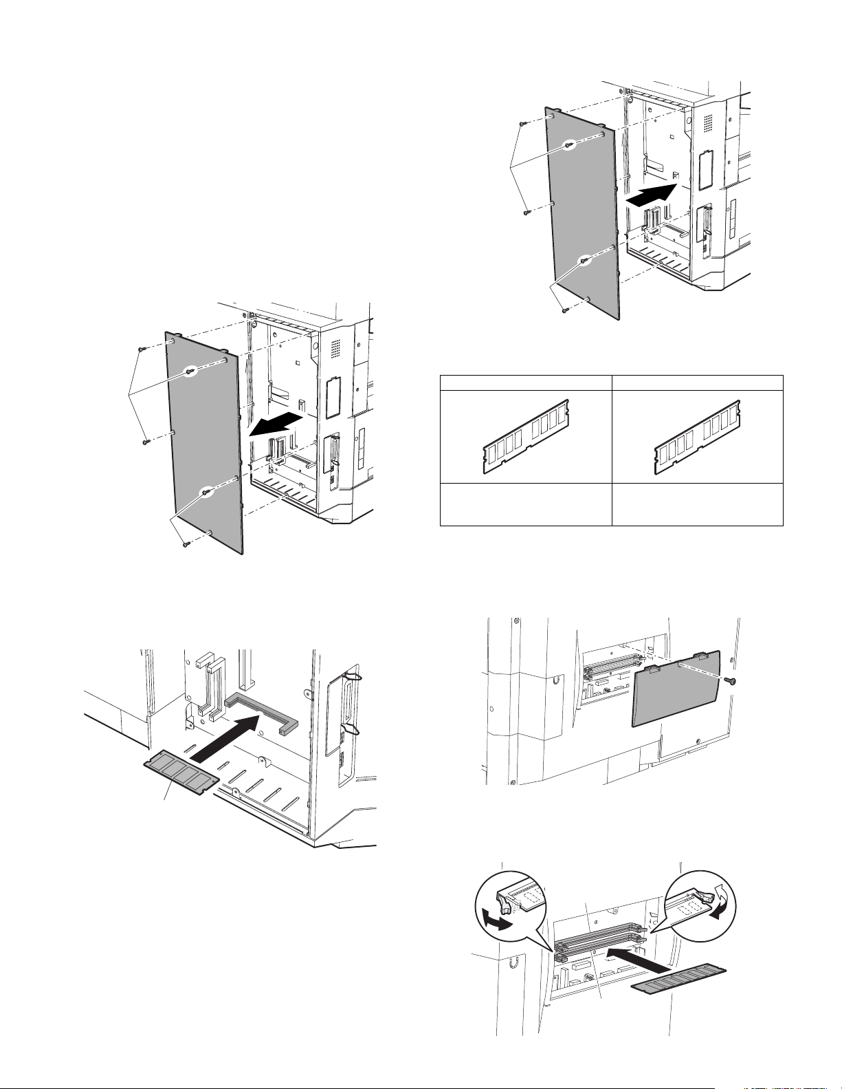
AR-M256/M257/M258/M316/M317/M318/5625/5631 UNPACKING AND INSTALLATION 5 - 8
1) Check the capacity of the Printer PWB memory.
Use the keys of the copier to print the configuration page.
(For details, see the operation manual.)
Check that the capacity of the optional memory is 128 MB or more.
2) Enable the network scanner feature.
To enable the system configuration, use the keys on the copier to
set the mode.
Enter the product key with the key operator program.
(Refer to the Operation Manual of Key Operator Program.)
Setting of the product key is completed. Press the [EXIT] key to
update the system and exit the setting mode.
(3) Mounting the additional memory
Turn off the main switch of the copier and then remove the power
plug of the copier from the outlet.
1) Remove the shielding plate.
Remove the five screws and remove the shielding plate.
2) Mount the memory module.
Insert the memory module until it clicks.
The memory module is lock when it is inserted. However, be sure
to check that the module slit is engaged with the connector rib
when it is inserted.
3) Reattach the shielding plate.
Reattach the shielding plate using the five screws.
F. AR-SM5/SM6
(1) Parts included
(2) Installation procedure
Turn off the main switch of the copier and then remove the power
plug of the copier from the outlet.
1) Remove the shielding plate.
Remove the screw and remove the cabinet.
2) Attach the SDRAM memory module.
Attach the SDRAM memory module to CN1 and CN2 of the IMC
board.
When only one SDRAM memory module is used, attach it to CN1.
Screws
Screws
Memory module
(S.O.DIMM)
AR-SM5 AR-SM6
256MB SDRAM memory module
(168 pin DIMM): 1 pc.
Installation caution sheet
512MB SDRAM memory module
(168 pin DIMM): 1 pc.
Installation caution sheet
Screws
Screws
CN1
CN2
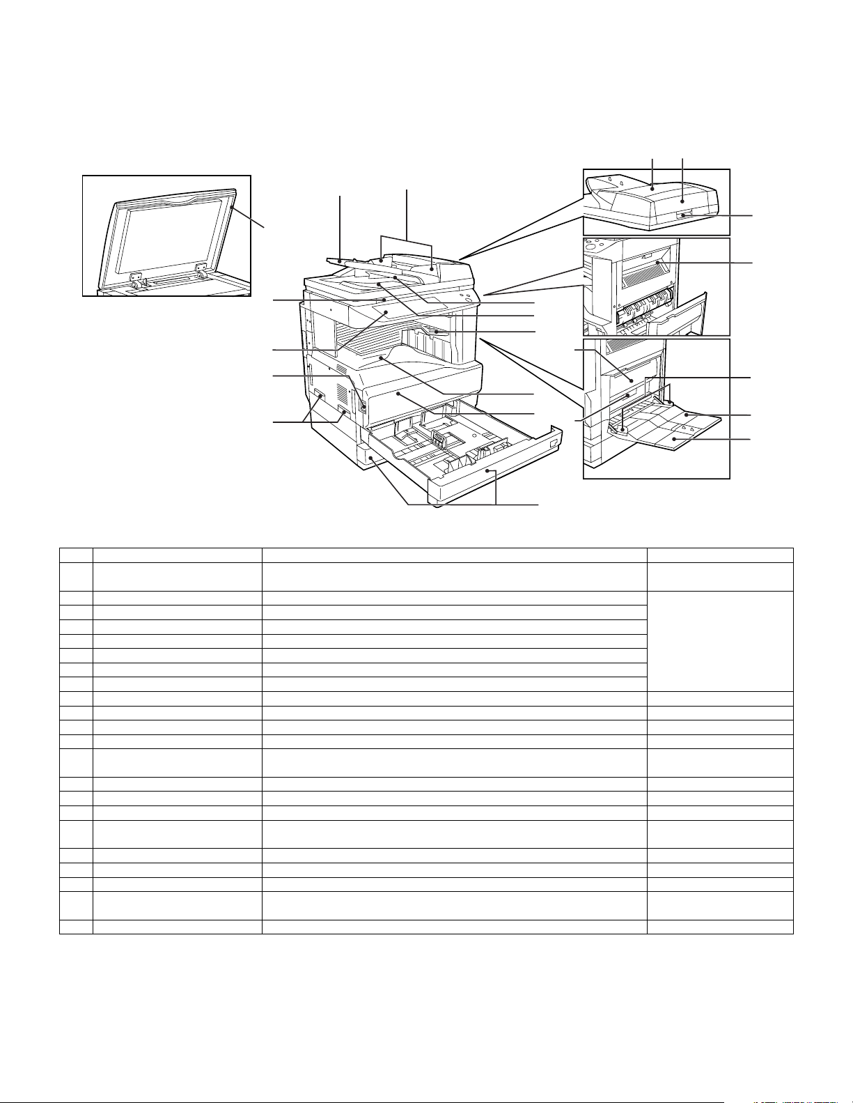
AR-M256/M257/M258/M316/M317/M318/5625/5631 EXTERNAL VIEW AND INTERNAL STRUCTURE 6 - 1
[6] EXTERNAL VIEW AND INTERNAL STRUCTURE
1. Name and function of each section
A. External view
No. Name Function/Operation Note
1 Document cover (optional) Presses a document. Optional (AR-M256/M258/
M316/M318/5625/5631)
2 Document feeder tray Place the original(s) that you wish to scan face up here. When the reversing single
pass feeder is installed.
(AR-M257/M317:Standard)
3 Original guides Adjust to the size of the originals.
4 Document feeder cover Open to remove misfed originals.
5 Reversing tray Pull out to remove misfed originals.
6 Exit area Originals exit the machine here after copying.
7 Document transport cover Open to remove misfed originals.
8 Document transport cover knob Pull to open the document transport cover.
9 Document glass Place an original that you wish to scan face down here.
10 Power switch Press to turn the machine power on and off.
11 Handles Use to move the machine.
12 Operation panel Contains operation keys and the touch panel.
13 Job separator tray (Upper tray)
(optional)
Print jobs and received faxes are delivered to this tray. When the job separator
tray installed.
14 Center tray Finished copies are delivered to the center tray.
15 Front cover Open to remove paper misfeeds and perform machine maintenance.
16 Paper trays Each tray holds 500 sheets of copy paper.
17 Upper right side cover Open to remove misfeeds when an optional job separator tray kit or a
optional finisher is installed.
18 Side cover Open to remove misfeeds.
19 Side cover handle Pull to open the side cover.
20 Bypass tray paper guides Adjust to the width of the paper.
21 Bypass tray Regular paper and special paper (such as transparency film) can be fed
from the bypass tray.
22 Bypass tray extension Pull out the bypass tray extension before placing paper in the bypass tray.
2
22
21
20
18
15
19
17
6
3
10
9
11
14
13
5
8
74
12
16
1
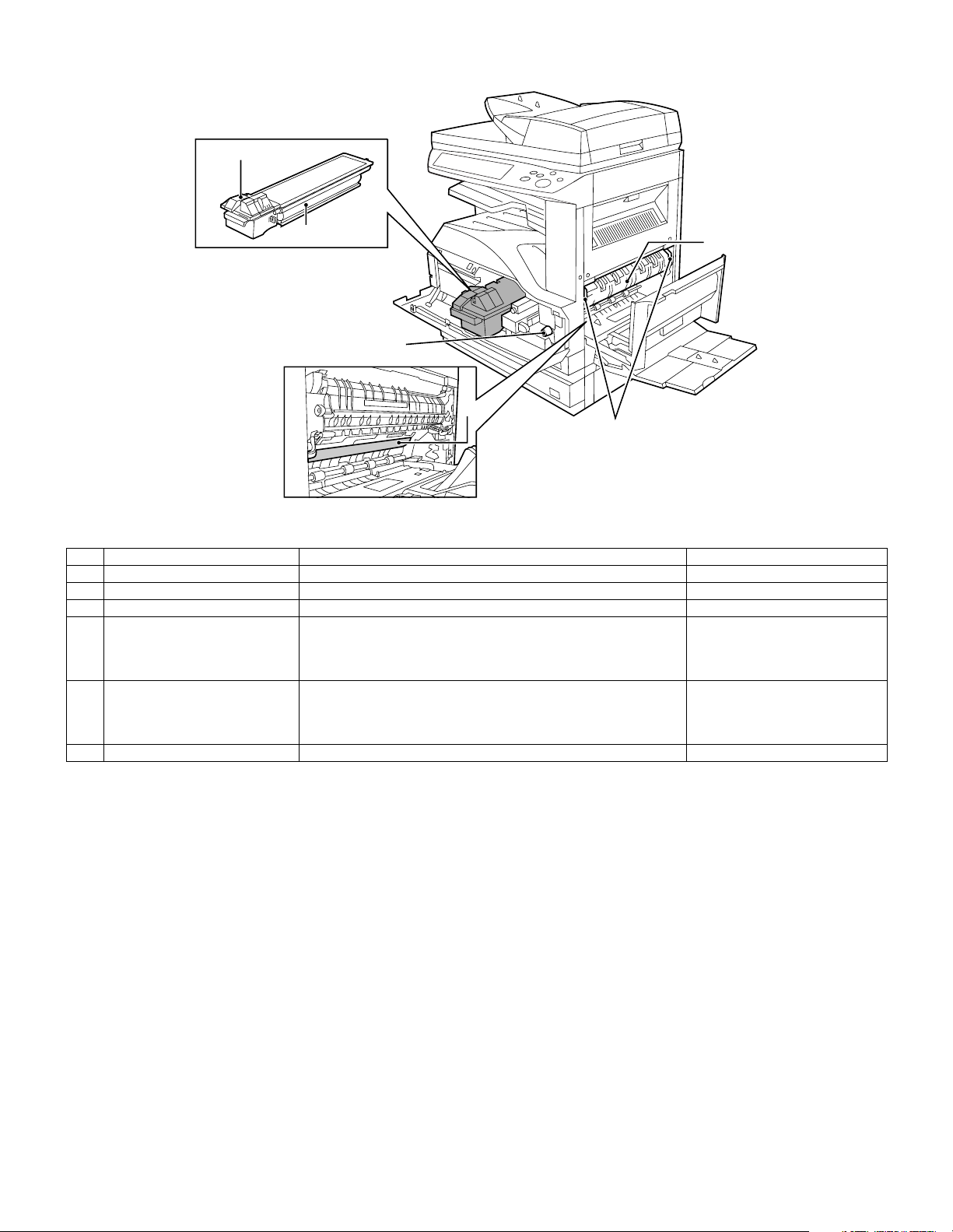
AR-M256/M257/M258/M316/M317/M318/5625/5631 EXTERNAL VIEW AND INTERNAL STRUCTURE 6 - 2
B. Internal structure
No. Name Function/Operation Note
1 Toner cartridge lock release lever Use to unlock the toner cartridge.
2 Toner cartridge Contains toner.
3 Roller rotating knob Turn to remove misfed paper.
4 Photoconductive drum Copy images are formed on the photoconductive drum. Do not touch the photoconductive
drum (green portion). Doing so
may damage the drum and cause
smudges on copies.
5 Fusing unit release levers To remove a paper misfeed in the fusing unit, push up on these
levers and remove the paper.
The fusing unit is hot. Do not
touch the fusing unit when
removing misfed paper. Doing so
may cause a burn or injury.
6 Fusing unit paper guide Open to remove misfed paper.
2
1
3
4
6
5
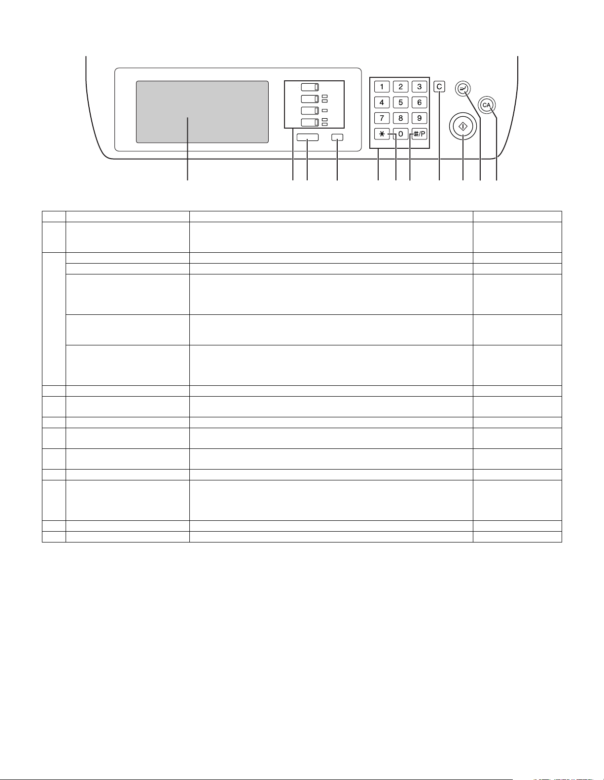
AR-M256/M257/M258/M316/M317/M318/5625/5631 EXTERNAL VIEW AND INTERNAL STRUCTURE 6 - 3
C. Operation panel
No. Name Function/Operation Note
1 Touch panel The machine status, messages and touch keys are displayed on the panel. The
display will show the status of printing, copying or network scanning according
to the mode that is selected.
2 Mode select keys and indicators Use to change modes and the corresponding display on the touch panel.
[COPY] key Press to select copy mode.
[PRINT] key/ONLINE indicator/
DATA indicator
[PRINT] key: Press to select print mode.
• ONLINE indicator: Print jobs can be received when this indicator is lit.
• DATA indicator: A print job is in memory. The indicator lights steadily while
the job is held in memory, and blinks while the job is printed.
[SCAN] key/DATA indicator [SCAN] key: Press to select network scan mode when the network scanner
option is installed.
• DATA indicator: Lights steadily or blinks while a scanned image is being sent.
When the network
scanner option is
installed.
[FAX] key/LINE indicator/
DATA indicator
[FAX] key: Press to select fax mode when the fax function is installed.
• LINE indicator : This lights up while faxes are being sent or received.
• DATA indicator: Blinks when a fax has been received to memory and lights
steadily when a fax is waiting in memory for transmission.
When the fax option is
installed.
3 [JOB STATUS] key Press to display the current job status.
4 [CUSTOM SETTINGS] key Use to adjust various settings of the machine including the contrast of the touch
panel and key operator programs.
5 Numeric keys Use to enter numeric values for various settings.
6 [ACC.#-C] key When auditing mode is enabled, press this key after finishing a job to return the
machine to account number entry standby.
7 [#/P] key Use this key to execute a job program in copy mode. The key is also used to
dial in fax mode.
8 [CLEAR] key Press to clear a copy number setting or cancel a job.
9 [START] key Press in copy mode, scanner mode, or fax mode to begin copying, network
scanning, or faxing.
This key blinks when auto power shut mode has activated. Press the key to
return to normal operation.
10 [INTERRUPT] key Use to perform an interrupt copy job.
11 [CLEAR ALL] key Resets the settings to the initial settings.
COPY
PRINT
SCAN
FAX
ON LINE
DATA
DATA
DATA
LINE
JOB STATUS
CUST OM SETTINGS
AC C.#-C
9
10 11
23 4 5 67 81
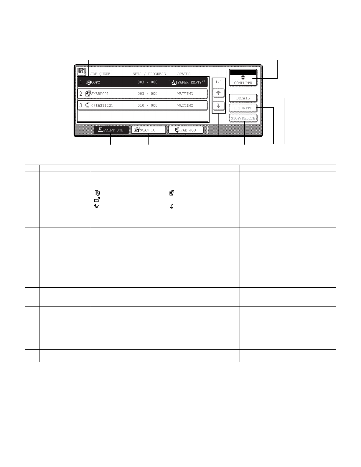
AR-M256/M257/M258/M316/M317/M318/5625/5631 EXTERNAL VIEW AND INTERNAL STRUCTURE 6 - 4
D. Job status screen (common to copy, print, network scan and fax)
This screen appears when the [JOB STATUS] key on the operation panel is pressed.
A job list showing the current job and the stored jobs or a list showing completed jobs can be displayed.
The contents of jobs can be viewed and jobs can be deleted from the queue. The following screen shows the job queue for print jobs.
No. Name Function/Operation Note
1 Job list Shows stored jobs and the job currently being executed. Touch one of
keys 3 to 5 in the above illustration to select the type of job. The icon
next to each job name indicates the mode of the job as follows:
* 1 :"PAPER EMPTY" in the job status
display
"PAPER EMPTY" in the job status display
indicates that the machine is out of the
specified size of paper. Add the specified
size of paper. If the specified size of paper
is not available and you are in printer mode,
another size of paper can be loaded in the
bypass tray to allow printing to take place.
Copy mode Printer mode
Network scanner mode
Fax mode (Send jobs) Fax mode (Receive jobs)
The jobs in the job list appear in the form of keys. To give priority to a
job or pause or delete a job, touch the key of the job and then use the
key described in 7 or 8.
2 Mode switching keys Use to select the job list mode: "JOB QUEUE" (Stored/currently
executing jobs) or "COMPLETE" (Finished jobs).
"JOB QUEUE": Shows jobs that have been stored and the job that is
currently being executed.
"COMPLETE" : Shows the jobs that have been finished. Note that
copy jobs do not appear in this list.
If the power is turned off, or if auto power shut-off
mode activates when there are no jobs, the jobs in
the "COMPLETE" list will be erased.
3 [PRINT JOB] key Use to view the list of output jobs for all modes (print, copy, and fax).
4 [SCAN TO] key Displays a network scanner job. When the network scanner function is
installed.
5 [FAX JOB] key This displays stored fax jobs and the fax job currently being executed. When the fax option is installed.
6 Display switching keys Use to change the page of the displayed job list.
7 [STOP/DELETE] key Use to pause or delete a job currently being executed, or to delete a
stored job. Copy jobs and received faxes cannot be paused or deleted
with this key. Copy jobs can be canceled by pressing the [CLEAR] key
or [CLEAR ALL] key.
8 [PRIORITY] key Touch this key after selecting a stored job in this [JOB QUEUE] list to
print the job ahead of the other jobs.
9 [DETAIL] key Shows information on the selected job. This cannot be used for a
received fax.
1 2
9345678
Loading...