


 Loading...
SERVICE MANUAL
CODE: 00ZARM277/A1E
DIGITAL MULTIFUNCTIONAL
SYSTEM
AR-M236/M276
MODEL
AR-M236/M276 AR-M237/M277
AR-M237/M277
CONTENTS
[1] NOTE FOR SERVICING . . . . . . . . . . . . . . . . . . . . . . . . . . . . . . . . 1-1
[2] SYSTEM CONFIGURATION . . . . . . . . . . . . . . . . . . . . . . . . . . . . . 2-1
[3] SPECIFICATIONS . . . . . . . . . . . . . . . . . . . . . . . . . . . . . . . . . . . . . 3-1 [4] CONSUMABLE PARTS . . . . . . . . . . . . . . . . . . . . . . . . . . . . . . . . . 4-1
[5] UNPACKING AND INSTALLATION . . . . . . . . . . . . . . . . . . . . . . . . 5-1
[6] EXTERNAL VIEW AND INTERNAL STRUCTURE . . . . . . . . . . . . 6-1 [7] ADJUSTMENTS, SETTING . . . . . . . . . . . . . . . . . . . . . . . . . . . . . . 7-1
[8] SIMULATION . . . . . . . . . . . . . . . . . . . . . . . . . . . . . . . . . . . . . . . . . 8-1 [9] TROUBLE CODE LIST. . . . . . . . . . . . . . . . . . . . . . . . . . . . . . . . . . 9-1
[10] DISASSEMBLY, ASSEMBLY AND MAINTENANCE . . . . . . . . . . 10-1
[11] OTHERS. . . . . . . . . . . . . . . . . . . . . . . . . . . . . . . . . . . . . . . . . . . . 11-1 [12] ELECTRICAL SECTION. . . . . . . . . . . . . . . . . . . . . . . . . . . . . . . . 12-1
Parts marked with “ ” are important for maintaining the safety of the set. Be sure to replace these parts with specified ones for maintaining the safety and performance of the set.
This document has been published to be used
SHARP CORPORATION for after sales service only.
The contents are subject to change without notice.
CONTENTS
[1]NOTE FOR SERVICING
1. Warning for servicing . . . . . . . . . . . . . . . . . . . . . . . . . . . . . . 1-1 2. Precautions for servicing . . . . . . . . . . . . . . . . . . . . . . . . . . . 1-1 3. Note for installing site . . . . . . . . . . . . . . . . . . . . . . . . . . . . . 1-1
[2]CONFIGURATION
1. Product Line and options . . . . . . . . . . . . . . . . . . . . . . . . . . . 2-1 A. Line of machines . . . . . . . . . . . . . . . . . . . . . . . . . . . . . . . 2-1 B. Line of options. . . . . . . . . . . . . . . . . . . . . . . . . . . . . . . . . 2-1 C. Combination of options list . . . . . . . . . . . . . . . . . . . . . . . 2-2
[3]SPECIFICATIONS
1. Basic specifications . . . . . . . . . . . . . . . . . . . . . . . . . . . . . . . 3-1 2. Operation specifications . . . . . . . . . . . . . . . . . . . . . . . . . . . 3-1 A. Common operation . . . . . . . . . . . . . . . . . . . . . . . . . . . . . 3-1 B. Copy mode . . . . . . . . . . . . . . . . . . . . . . . . . . . . . . . . . . . 3-1 3. Engine specifications . . . . . . . . . . . . . . . . . . . . . . . . . . . . . . 3-2 A. Operation and display section . . . . . . . . . . . . . . . . . . . . . 3-2 B. Paper feed, transport, paper exit section . . . . . . . . . . . . 3-2 C. Optical (Image scanning) section . . . . . . . . . . . . . . . . . . 3-3 D. Scanner (exposure) section . . . . . . . . . . . . . . . . . . . . . . 3-3 E. Image process section . . . . . . . . . . . . . . . . . . . . . . . . . . 3-3 F. Fusing . . . . . . . . . . . . . . . . . . . . . . . . . . . . . . . . . . . . . . . 3-3 G. Drive . . . . . . . . . . . . . . . . . . . . . . . . . . . . . . . . . . . . . . . . 3-3
4. Additional functions, copy functions, and expanded
functions. . . . . . . . . . . . . . . . . . . . . . . . . . . . . . . . . . . . . . . . 3-4 5. Safety and environmental protection standards . . . . . . . . . 3-4 6. Environment conditions . . . . . . . . . . . . . . . . . . . . . . . . . . . . 3-5 7. IMC board functions. . . . . . . . . . . . . . . . . . . . . . . . . . . . . . . 3-5 8. “Sharp Printer Language with Compression (SPLC)”
Printer function. . . . . . . . . . . . . . . . . . . . . . . . . . . . . . . . . . . 3-5 A. Basic specification. . . . . . . . . . . . . . . . . . . . . . . . . . . . . . 3-5 B. Printer driver specification . . . . . . . . . . . . . . . . . . . . . . . . 3-6 C. Interface . . . . . . . . . . . . . . . . . . . . . . . . . . . . . . . . . . . . . 3-8 D. System outline. . . . . . . . . . . . . . . . . . . . . . . . . . . . . . . . . 3-8
[4]CONSUMABLE PARTS
1. List . . . . . . . . . . . . . . . . . . . . . . . . . . . . . . . . . . . . . . . . . . . . 4-1 A. SEC/LAG/SECL . . . . . . . . . . . . . . . . . . . . . . . . . . . . . . . 4-1 B. SEEG/SUK/SCA/SCNZ/SEA/SEES/SEZ/SEIS/SEB/
SEN/SEF/SMEF/Russia/Special country . . . . . . . . . . . . 4-1 C. STCL/SRH/SRS/SRSSC/SBI/Agent . . . . . . . . . . . . . . . . 4-2 2. Production number identification . . . . . . . . . . . . . . . . . . . . . 4-3 3. Environment conditions . . . . . . . . . . . . . . . . . . . . . . . . . . . . 4-3 A. Ambient conditions for transporting. . . . . . . . . . . . . . . . . 4-3 B. Ambient storage conditions (sealed) . . . . . . . . . . . . . . . . 4-3 C. Operating ambient conditions . . . . . . . . . . . . . . . . . . . . . 4-3 4. Life (packed conditions). . . . . . . . . . . . . . . . . . . . . . . . . . . . 4-3
[5]UNPACKING AND INSTALLATION
1. Installation . . . . . . . . . . . . . . . . . . . . . . . . . . . . . . . . . . . . . . 5-1 A. Environment . . . . . . . . . . . . . . . . . . . . . . . . . . . . . . . . . . 5-1 B. Power source . . . . . . . . . . . . . . . . . . . . . . . . . . . . . . . . . 5-1 C. Transport . . . . . . . . . . . . . . . . . . . . . . . . . . . . . . . . . . . . . 5-1 D. Other precautions . . . . . . . . . . . . . . . . . . . . . . . . . . . . . . 5-2
2. Removal of protective material and fixing screw . . . . . . . . . 5-2 3. Removal and storage of fixing pin . . . . . . . . . . . . . . . . . . . . 5-2 4. Developer cartridge installation . . . . . . . . . . . . . . . . . . . . . . 5-3 5. Toner cartridge installation . . . . . . . . . . . . . . . . . . . . . . . . . 5-3 6. Toner density sensor level adjustment . . . . . . . . . . . . . . . . 5-4 7. Tray paper size setting . . . . . . . . . . . . . . . . . . . . . . . . . . . . 5-4
A. Trays 1 – 4 . . . . . . . . . . . . . . . . . . . . . . . . . . . . . . . . . . . 5-4 B. Manual feed tray . . . . . . . . . . . . . . . . . . . . . . . . . . . . . . . 5-4 8. Installation of options . . . . . . . . . . . . . . . . . . . . . . . . . . . . . . 5-5 A. AR-P17 . . . . . . . . . . . . . . . . . . . . . . . . . . . . . . . . . . . . . . 5-5 B. AR-PK1 . . . . . . . . . . . . . . . . . . . . . . . . . . . . . . . . . . . . . . 5-6 C. AR-PF1/PF2 . . . . . . . . . . . . . . . . . . . . . . . . . . . . . . . . . . 5-6 D. AR-NC5J . . . . . . . . . . . . . . . . . . . . . . . . . . . . . . . . . . . . . 5-7 E. AR-NS2 . . . . . . . . . . . . . . . . . . . . . . . . . . . . . . . . . . . . . . 5-8 F. AR-SM5/SM6 . . . . . . . . . . . . . . . . . . . . . . . . . . . . . . . . . 5-9
[6] EXTERNAL VIEW AND INTERNAL STRUCTURE
1. Name and function of each section . . . . . . . . . . . . . . . . . . 6-1 A. External view . . . . . . . . . . . . . . . . . . . . . . . . . . . . . . . . . 6-1 B. Internal structure . . . . . . . . . . . . . . . . . . . . . . . . . . . . . . 6-2 C. Operation panel . . . . . . . . . . . . . . . . . . . . . . . . . . . . . . . 6-2 D. Job status screen . . . . . . . . . . . . . . . . . . . . . . . . . . . . . . 6-3 E. Motor, Solenoid, Clutch . . . . . . . . . . . . . . . . . . . . . . . . . 6-4 F. Sensor . . . . . . . . . . . . . . . . . . . . . . . . . . . . . . . . . . . . . . 6-4 G. PWB unit . . . . . . . . . . . . . . . . . . . . . . . . . . . . . . . . . . . . 6-5 H. Section . . . . . . . . . . . . . . . . . . . . . . . . . . . . . . . . . . . . . . 6-5
[7]ADJUSTMENTS, SETTING
1. List of adjustment items . . . . . . . . . . . . . . . . . . . . . . . . . . . 7-1 2. Copier adjustment. . . . . . . . . . . . . . . . . . . . . . . . . . . . . . . . 7-1 A. Process section . . . . . . . . . . . . . . . . . . . . . . . . . . . . . . . 7-1 B. Mechanism section. . . . . . . . . . . . . . . . . . . . . . . . . . . . . 7-2 C. Image density (exposure) adjustment . . . . . . . . . . . . . . 7-9
[8]SIMULATION
1. Outline and purpose . . . . . . . . . . . . . . . . . . . . . . . . . . . . . . 8-1 2. Code-type simulation . . . . . . . . . . . . . . . . . . . . . . . . . . . . . 8-1 A. Operating procedures and operations . . . . . . . . . . . . . . 8-1
B. How to change the simulation adjustment value set by the touch panel in the adjustment value entry process . . . . 8-1
3. Simulation code list. . . . . . . . . . . . . . . . . . . . . . . . . . . . . . . 8-3 4. Details. . . . . . . . . . . . . . . . . . . . . . . . . . . . . . . . . . . . . . . . . 8-6
[9]TROUBLE CODE LIST
1. List . . . . . . . . . . . . . . . . . . . . . . . . . . . . . . . . . . . . . . . . . . . 9-1 2. Self diagnostics. . . . . . . . . . . . . . . . . . . . . . . . . . . . . . . . . . 9-2
[10] DISASSEMBLY, ASSEMBLY AND MAINTENANCE
1. Maintenance table . . . . . . . . . . . . . . . . . . . . . . . . . . . . . . 10-1 2. Counter clear . . . . . . . . . . . . . . . . . . . . . . . . . . . . . . . . . . 10-1 3. List of disassembly and assembly . . . . . . . . . . . . . . . . . . 10-1 4. Details of disassembly and assembly . . . . . . . . . . . . . . . . 10-2 A. Process unit . . . . . . . . . . . . . . . . . . . . . . . . . . . . . . . . . 10-2 B. Developing section . . . . . . . . . . . . . . . . . . . . . . . . . . . . 10-3 C. Fusing section . . . . . . . . . . . . . . . . . . . . . . . . . . . . . . . 10-5 D. Optical section . . . . . . . . . . . . . . . . . . . . . . . . . . . . . . . 10-6 E. Paper feed section . . . . . . . . . . . . . . . . . . . . . . . . . . . . 10-8 F. Side door unit . . . . . . . . . . . . . . . . . . . . . . . . . . . . . . . 10-13 G. 1st paper exit unit . . . . . . . . . . . . . . . . . . . . . . . . . . . . 10-14 H. 2nd paper exit unit. . . . . . . . . . . . . . . . . . . . . . . . . . . 10-16 I. Laser unit . . . . . . . . . . . . . . . . . . . . . . . . . . . . . . . . . . 10-16 J. Power unit . . . . . . . . . . . . . . . . . . . . . . . . . . . . . . . . . 10-17 K. PWB . . . . . . . . . . . . . . . . . . . . . . . . . . . . . . . . . . . . . . 10-17 L. Ozone filter . . . . . . . . . . . . . . . . . . . . . . . . . . . . . . . . . 10-19 M. Drive section. . . . . . . . . . . . . . . . . . . . . . . . . . . . . . . . 10-20 N. Transport section . . . . . . . . . . . . . . . . . . . . . . . . . . . . 10-22 O. Operation section . . . . . . . . . . . . . . . . . . . . . . . . . . . . 10-22 P. Switch. . . . . . . . . . . . . . . . . . . . . . . . . . . . . . . . . . . . . 10-23
[11] OTHERS
1. Flash ROM version-up procedure. . . . . . . . . . . . . . . . . . . 11-1 A. Program download method
(for Copier, and fax program) . . . . . . . . . . . . . . . . . . . . . 11-1 B. Printer Control Board firmware download method . . . . 11-2 C. Others (Troubleshooting) . . . . . . . . . . . . . . . . . . . . . . . 11-3 2. Key operator program list . . . . . . . . . . . . . . . . . . . . . . . . . 11-3 A. Common program of digital copier . . . . . . . . . . . . . . . . 11-3 B. Copy function setting program . . . . . . . . . . . . . . . . . . . 11-4 C. Printer function setting program . . . . . . . . . . . . . . . . . . 11-4 D. Network scanner function setting program. . . . . . . . . . 11-5 3. E-mail Status/E-mail Alerts . . . . . . . . . . . . . . . . . . . . . . . . 11-6 A. Basic functions . . . . . . . . . . . . . . . . . . . . . . . . . . . . . . . 11-6 B. Main body specifications . . . . . . . . . . . . . . . . . . . . . . . 11-6 C. Printer controller specifications . . . . . . . . . . . . . . . . . . 11-6 D. Handling of transmission data . . . . . . . . . . . . . . . . . . . 11-6
[12] ELECTRICAL SECTION |
|
|
1. |
Block diagram . . . . . . . . . . . . . . . . . . . . . . . . . . . . . . . . . |
12-1 |
2. |
Actual wiring diagram . . . . . . . . . . . . . . . . . . . . . . . . . . . |
12-2 |
[1] NOTE FOR SERVICING
This Service Manual uses some photographs to assure safe operation.
This Service Manual uses some photographs to assure safe operation. Please understand the meanings of photographs before servicing.
 WARNING: If this WARNING should be ignored, a serious danger to life or a serious injury would be resulted.
 CAUTION: If this CAUTION should be ignored, an injury or a damage to properties would be resulted.
1. Warning for servicing
1)Be sure to connect the power cord only to a power outlet that meets the specified voltage and current requirements.
Avoid complex wiring, which may lead to a fire or an electric shock. It may cause a fire or an electric shock.
2)If there is any abnormality such as a smoke or an abnormal smell, interrupt the job and disconnect the power plug.
It may cause a fire or an electric shock.
3)Be sure to connect the grounding wire. If an electric leakage occurs without grounding, a fire or an electric shock may be the result.
To protect the machine and the power unit from lightening, grounding must be made.
4)When connecting the grounding wire, never connect it to the following points.
It may cause an explosion, a fire or an electric shock.
•Gas tube
•Lightning conductor
•A water pipe or a water faucet, which is not recognized as a grounding object by the authorities.
•Grounding wire for telephone line
5)Do not damage, brake, or work the power cord.
Do not put heavy objects on the power cable. Do not bend it forcibly or do not pull it extremely.
It may cause a fire or an electric shock.
6)Keep the power cable away from a heat source.
Do not insert the power plug with dust on it into a power outlet. It may cause a fire or an electric shock.
7)Do not put a receptacle with water in it or a metal piece which may drop inside the machine.
It may cause a fire or an electric shock.
8)With wet or oily hands, do not touch the power plug, do not insert the telephone line jack, do not operate the machine, or do not perform servicing.
It may cause an electric shock.
2. Precautions for servicing
1)When servicing, disconnect the power plug, the printer cable, the network cable, and the telephone line from the machine, except when performing the communication test, etc.
It may cause an injury or an electric shock.
2)There is a high temperature area inside the machine. Use an extreme care when servicing.
It may cause a burn.
3)There is a high voltage section inside the machine which may cause an electric shock . Be careful when servicing.
4)Do not disassemble the laser unit. Do not insert a reflective material such as a screwdriver in the laser beam path.
It may damage eyes by reflection of laser beams.
5)When servicing with the machine operating, be careful not to squeeze you hands by the chain, the belt, the gear, and other driving sections.
6)Do not leave the machine with the cabinet disassembled.
Do not allow any person other than a serviceman to touch inside the machine. It may cause an electric shock, a burn, or an injury.
7)When servicing, do not breathe toner, developer, and ink excessively. Do not get them in the eyes.
If toner, developer, or ink enters you eyes, wash it away with water immediately, and consult a doctor if necessary.
8)The machine has got sharp edges inside. Be careful not to damage fingers when servicing.
9)Do not throw toner or a toner cartridge in a fire. Otherwise, toner may pop and burn you.
10)When replacing the lithium battery of the PWB, use a specified one only.
If a battery of different specification is used, it may be broken, causing breakdown or malfunction of the machine.
11)When carrying a unit with PWB or electronic parts installed to it, be sure to put it in an anti-static-electricity bag.
It may cause a breakdown or malfunctions.
3. Note for installing site
Do not install the machine at the following sites.
1)Place of high temperature, high humidity, low temperature, low humidity, place under an extreme change in temperature and humidity.
Paper may get damp and form dews inside the machine, causing paper jam or copy dirt.
For operating and storing conditions, refer to the specifications described later.
2)Place of much vibrations
It may cause a breakdown.
3)Poorly ventilated place
An electro-static type copier will produce ozone inside it.
The quantity of ozone produced is designed to a low level so as not to affect human bodies. However, continuous use of such a machine may produce a smell of ozone. Install the machine in a well ventilated place, and ventilate occasionally.
4)Place of direct sunlight.
Plastic parts and ink may be deformed, discolored, or may undergo qualitative change.
It may cause a breakdown or copy dirt.
5)Place which is full of organic gases such as ammonium
The organic photoconductor (OPC) drum used in the machine may undergo qualitative change due to organic gases such as ammonium.
Installation of this machine near a diazo-type copier may result in dirt copy.
6)Place of much dust
When dusts enter the machine, it may cause a breakdown or copy dirt.
7)Place near a wall
Some machine require intake and exhaust of air.
If intake and exhaust of air are not properly performed, copy dirt or a breakdown may be resulted.
8)Unstable or slant surface
If the machine drops or fall down, it may cause an injury or a breakdown.
If there are optional paper desk and the copier desk specified, it is recommendable to use them.
When using the optional desk, be sure to fix the adjuster and lock the casters.
AR-M236/M276/M237/M277 NOTE FOR SERVICING 1 - 1
[2] CONFIGURATION
1. Product Line and options
A. Line of machines
Model name |
Composition |
Model name |
Composition |
AR-M277/M237 (For SEC/SECL) |
Copier/Printer (SPLC) model |
AR-M276/M236 |
Copier/Printer (SPLC) model |
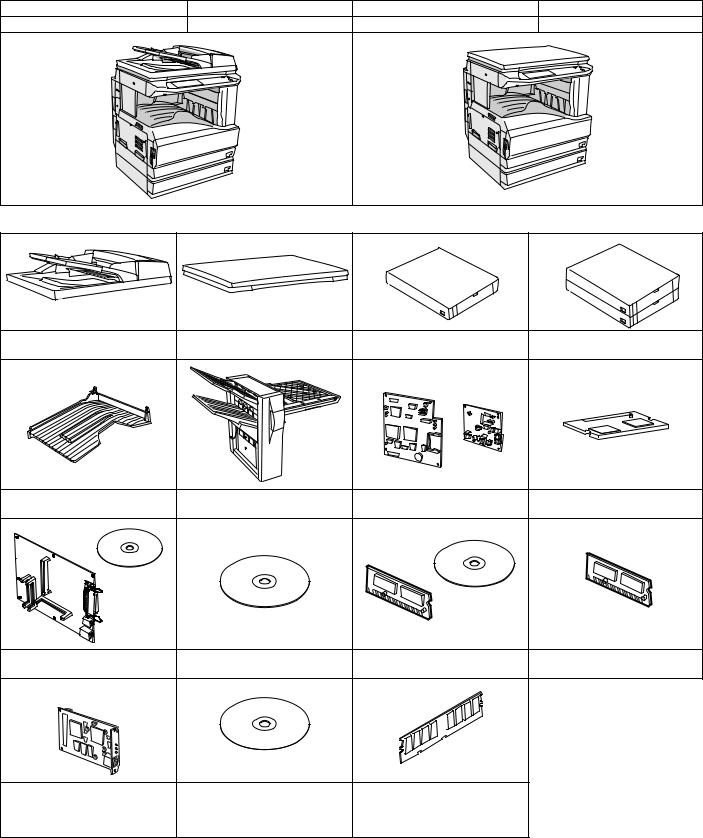
B. Line of options
AR-RP7 |
AR-VR6 |
AR-D21 |
AR-D22 |
Reversing single pass feeder |
Platen cover (OC) |
500-sheet paper feed unit |
2X500-sheet paper feed unit |
AR-TR3 |
AR-FN5N |
AR-FX7 |
AR-MM9 |
Job separator tray kit |
Finisher |
Facsimile expansion kit |
8MB FAX memory |
AR-P17 |
AR-PK1/N |
AR-PF1 |
AR-PF2 |
Printer expansion kit |
PS3 expansion kit |
Bar code font kit |
Flash ROM kit |
|
|
AR-SM5 |
AR-NC5J |
AR-NS2 |
256MB expansion memory board |
Print server card |
Network scanner expansion kit |
AR-SM6 |
|
|
512MB expansion memory board |
AR-M236/M276/M237/M277 CONFIGURATION 2 - 1
C. Combination of options list
: Installable
: Not available
Section |
Option |
|
Main unit Model |
Note |
||
|
|
|
|
|||
Item |
Model |
AR-M237/M277 |
AR-M236/M276 |
|||
|
|
|||||
|
|
|
|
|
|
|
Automatic document |
Reversing single pass feeder |
AR-RP7 |
Standard |
|
|
|
feeder and OC |
|
|
|
|
|
|
Platen cover (OC) |
AR-VR6 |
|
|
|
||
|
|
|
|
|
|
|
Paper feed system |
500-sheet paper feed unit |
AR-D21 |
|
|
500 x 1 (80g/m2) |
|
|
2X500-sheet paper feed unit |
AR-D22 |
|
|
500 x 2 (80g/m2) |
|
Paper exit system |
Job separator tray kit |
AR-TR3 |
|
|
|
|
|
|
|
|
|
|
|
|
Finisher |
AR-FN5N |
|
|
|
|
|
|
|
|
|
|
|
|
Staple cartridge |
AR-SC1 |
|
|
For AR-FN5N |
|
|
|
|
|
|
|
|
FAX system |
Facsimile expansion kit |
AR-FX7 |
|
|
FAX board option available only for |
|
|
|
|
|
|
SEC/SECL/SEEG/SUK/SCA/SEIS/ |
|
|
|
|
|
|
SEES/SEB/SEN/SEF/SRS/STCL/ |
|
|
|
|
|
|
SRSSC/Philippines/SRH/SBI/SMEF/ |
|
|
|
|
|
|
South Africa/Taiwan/SOCC |
|
|
|
|
|
|
|
|
|
8MB FAX memory |
AR-MM9 |
|
|
|
|
|
|
|
|
|
|
|
|
PC-FAX (only sending) |
– |
|
|
|
|
|
|
|
|
|
|
|
Printer system |
Printer expansion kit |
AR-P17 |
|
|
|
|
|
|
|
|
|
|
|
|
Print server card |
AR-NC5J |
|
|
The AR-P17 must be installed. |
|
|
|
|
|
|
|
|
|
Bar code font kit |
AR-PF1 |
|
|
|
|
|
|
|
|
|
|
|
|
Flash ROM kit |
AR-PF2 |
|
|
|
|
|
|
|
|
|
|
|
|
PS3 expansion kit |
AR-PK1/N |
|
|
|
|
|
|
|
|
|
|
|
Memory board |
256MB expansion memory |
AR-SM5 |
|
|
|
|
(From July 2003 |
board |
|
|
|
|
|
onward) |
|
|
|
|
|
|
512MB expansion memory |
AR-SM6 |
|
|
|
||
|
board |
|
|
|
|
|
|
|
|
|
|
|
|
Software |
Network scanner expansion kit |
AR-NS2 |
|
|
The memory of 128MB must be added. |
|
|
|
|
|
|
|
|
For details of the options, refer to the Service Manual of each option.
AR-M236/M276/M237/M277 CONFIGURATION 2 - 2

[3] SPECIFICATIONS
This model is designed as an SPLC printer, and can be extended for use as a PCL6/PS3/NC/scanner by options. For details, refer to the Service Manual of the AR-P11/AR-PK1/AR-NC5J/AR-NS2.
1. Basic specifications
(1) Type
Machine Type |
Desktop type |
(2) External dimensions
Floor to OC top surface |
623 (W) x 609.5 (D) x 673 (H)mm |
|
(24.5 (W) x 24 (D) x 26.5 (H) inch) |
Floor to Glass surface |
623 (W) x 609.5 (D) x 640.5 (H)mm |
|
(24.5 (W) x 24 (D) x 25.2 (H) inch) |
Floor to RSPF surface |
623 (W) x 609.5 (D) x 785.5 (H)mm |
|
(24.5 (W) x 24 (D) x 30.9 (H) inch) |
(3) Weight
AR-M276/M236 |
41.8 kg (including DV), 39.8 kg (excluding DV) |
|
(92 lbs. (including DV), 87.7 lbs. (excluding DV)) |
AR-M277/M237 |
49.3 kg (including DV), 47.3 kg (excluding DV) |
|
(108.6 lbs. (including DV), 104.2 lbs. (excluding DV)) |
(4) Power supply
Voltage |
100V/110V/120V/127V/230V (common with 200V)/ |
|
240V |
Frequency |
50/60Hz common |
Power switch |
One power source |
2. Operation specifications
A. Common operation
(1) Warm up time
Warm-up time |
Under 23 sec. |
Pre-heat function |
Yes |
(2) Jam recovery time
About 10sec (Leaving the machine for 60 sec after opening the door, standard condition, polygon stop.)
B. Copy mode
(1) Document size
Max. document size |
A3 paper (11" × 17") |
(2) Picture quality mode
Picture quality mode |
Density |
Toner save mode |
|
adjustment step |
|||
|
|
||
Text Auto mode |
1 step |
Selectable |
|
Text mode |
5 steps |
Selectable |
|
Text/Photo mode |
5 steps |
Selectable |
|
Photo mode |
5 steps |
— |
|
Super Photo mode |
5 steps |
— |
(3) Copy magnification ratio
• |
Normal mode |
|
|
|
|
|
Copy magnification |
Magnification range/fixed magnification |
|
ratio |
|
|
|
|
|
Zoom width |
25 to 400% (50 to 200% for RSPF) |
|
Fixed magnification |
AB Series: 25, 50, 70, 81, 86, 100, 115, 122, |
|
mode |
141, 200, 400% |
|
|
5R+5E |
|
|
(50, 70, 81, 86, 100, 115, 122, 141 and 200% |
|
|
for RSPF) |
|
|
Inch Series: 25, 50, 64, 77, 100, 121, 129, |
|
|
200, 400% |
|
|
4R+4E |
|
|
(50, 64, 77, 100, 121, 129 and 200% for |
|
|
RSPF) |
|
Independent |
25 to 400% for horizontal/vertical |
|
magnification width |
(50 to 200% for RSPF) |
• |
1200 dpi mode |
|
|
|
|
|
Copy magnification |
Magnification range/fixed magnification |
|
ratio |
|
|
|
|
|
Zoom width |
50 to 200% (50 to 141% for RSPF) |
|
Fixed magnification |
AB Series: 50, 70, 81, 86, 100, 115, 122, 141, |
|
mode |
200% |
|
|
4R+4E |
|
|
(50, 70, 81, 86, 100, 115, 122 and 141% for |
|
|
RSPF) |
|
|
Inch Series: 50, 64, 77, 100, 121, 129, |
|
|
200% |
|
|
3R+3E |
|
|
(50, 64, 77, 100, 121 and 129% for RSPF) |
|
Independent |
50 to 200% for horizontal/vertical (50 to 141% |
|
magnification width |
for RSPF) |
|
|
|
|
Magnification |
Normal copy: 100%±1.0% |
|
precision |
Enlargement copy: Set magnification ±1.0% |
|
|
Reduction copy: Set magnification ±1.0% |
(4) Job speed |
|
|
a. First Copy Time |
|
|
|
|
|
|
Normal |
Less than 4.8 sec. (when the single copy) |
When paper of A4/Letter is fed from the upper cassette of the machine and discharged.
b. Copy speed
|
Mode |
|
|
|
AR-M276/M277 |
|
AR-M236/M237 |
|||||
1 scan multi |
|
(600 dpi) |
|
|
27 cpm |
|
23 cpm |
|||||
copy |
|
(1200 dpi) |
|
13.5 cpm |
|
13.5 cpm |
||||||
When A4/Letter |
|
|
|
|
|
|
|
|
|
|||
b. Multi copy speed |
(sheets/minute) |
|
|
|
||||||||
|
|
|
|
|
|
|
|
|
|
|
||
|
Document Size |
|
AR-M276/M277 |
|
|
AR-M236/M237 |
||||||
|
|
600 dpi |
1200 dpi |
|
600 dpi |
1200 dpi |
||||||
|
|
|
|
|
|
|||||||
A3 |
|
|
|
|
15 |
|
7.5 |
|
12 |
7.5 |
||
B4 |
|
|
|
|
17 |
|
8.5 |
|
14 |
8.5 |
||
A4 |
(Horizontal feed) |
|
27 |
|
13.5 |
|
23 |
13.5 |
||||
A4 |
(Vertical feed) |
|
18 |
|
9 |
|
16 |
9 |
||||
B5 |
(Horizontal feed) |
|
27 |
|
13.5 |
|
23 |
13.5 |
||||
B5 |
(Vertical feed) |
|
21 |
|
10.5 |
|
18 |
10.5 |
||||
11" × 17" |
|
|
|
14 |
|
7.5 |
|
12 |
7.5 |
|||
8-1/2" × 14" |
|
|
|
16 |
|
8 |
|
13 |
8 |
|||
8-1/2" × 13" |
|
|
|
17 |
|
8.5 |
|
14 |
8.5 |
|||
8-1/2" × 11" |
|
|
|
27 |
|
13.5 |
|
23 |
13.5 |
|||
(Horizontal feed) |
|
|
|
|
||||||||
|
|
|
|
|
|
|
|
|
|
|||
8-1/2" × 11" (Vertical |
|
18 |
|
9 |
|
16 |
9 |
|||||
feed) |
|
|
|
|
||||||||
|
|
|
|
|
|
|
|
|
|
|||
A5/INV |
|
|
27 |
|
13.5 |
|
23 |
13.5 |
||||
The slowest speed is listed in enlargement/reduction copy.
Single-side copy
AR-M236/M276/M237/M277 SPECIFICATIONS 3 - 1

(5) Max. multi-copy (print) quantity
999sheets
(6)Picture quality
a. Image process
|
Picture quality mode |
|
Image process (Software) |
|||||||
|
Text Auto mode |
|
|
|
|
• |
2 gradations |
|
||
|
Text mode |
|
|
|
|
• |
Area separation |
|||
|
Text/Photo mode |
|
|
|
|
• |
Error diffusion |
|
||
|
Photo mode |
|
|
|
|
|
|
|
|
|
|
Super Photo mode |
|
|
|
|
Dither |
|
|||
b. Toner save mode |
|
|
|
|
|
|
||||
|
|
|
|
|
|
|
|
|
|
|
|
Toner save percentage |
|
10% |
|
|
|
|
|||
c. Zoom method |
|
|
|
|
|
|
|
|
||
|
|
|
|
|
|
|
|
|
|
|
|
Main scanning |
|
|
|
Performed through image processing |
|||||
|
direction |
|
|
|
|
|
|
|
|
|
|
Sub scanning direction |
|
Performed by image processing and |
|||||||
|
|
|
|
|
|
changing scanning speed |
|
|||
d. Resolution |
|
|
|
|
|
|
|
|
||
• |
Read |
|
|
|
|
|
|
|
|
|
|
|
|
|
|
|
|
|
|||
|
Main scanning direction |
|
Sub scanning direction |
|||||||
|
400 dpi |
|
|
|
|
|
|
400 dpi |
||
• |
Write |
|
|
|
|
|
|
|
|
|
|
|
|
|
|
|
|
||||
|
Main scanning direction |
|
Sub scanning direction |
|||||||
|
Basic |
|
Virtual |
|
Basic |
Virtual |
||||
|
resolution |
|
resolution |
|
resolution |
resolution |
||||
|
600 dpi |
|
1200 dpi |
|
600 dpi |
1200 dpi |
||||
|
|
|
|
|
|
|
|
|
|
|
|
Copy magnification |
|
|
|
|
|
Position |
|
||
|
ratio |
|
|
|
Center |
|
|
Corners |
||
|
25% to 49% |
|
|
|
— |
|
|
— |
||
|
50% to 69% |
|
|
|
3.2 line/mm |
|
2.8 line/mm |
|||
|
70% to 94% |
|
|
|
3.6 line/mm |
|
3.2 line/mm |
|||
|
95% to 105% |
|
|
|
5.0 line/mm |
|
4.5 line/mm |
|||
|
106% to 141% |
|
|
|
5.0 line/mm |
|
4.5 line/mm |
|||
|
142% to 400% |
|
|
|
5.0 line/mm |
|
4.5 line/mm |
|||
e. Gradation |
|
|
|
|
|
|
|
|
||
|
|
|
|
|
|
|||||
|
Read |
|
|
256 gradations |
|
|||||
|
Write |
|
|
2 gradations |
|
|
|
|||
3. Engine specifications
A. Operation and display section
Display unit |
Touch panel |
Operation system |
Button switch system |
B. Paper feed, transport, paper exit section
(1) Paper feed ability
Paper feed |
2 cassettes + multi manual feed |
section |
|
Paper feed |
500 x 2 + 100 (80 g/m²) |
capacity |
|
Paper feed size |
AB Series: A3 to A6R |
|
Inch Series: 11"×17" to 8.5"×5.5" |
Remaining |
Cassette section: empty detection only available |
detection |
Manual paper feed section: empty detection only |
|
available |
• Details of paper feed section
Paper feed |
|
500 (80 g/m²) |
capacity |
|
|
Paper weight |
|
56 to 105 g/m² (15 to 28 lbs) |
Paper feed size |
|
A3/B4/A4/A4R/B5/B5R/A5/16K/16KR/8K |
|
|
8.5×11/8.5×14/11×17/8.5×13/8.5×11R/8.5×5.5 |
Paper kind |
|
Standard paper (56 to 80 g/m²), normal paper |
|
|
(80 to 105 g/m²), special paper |
Special paper |
|
Recycle paper |
Paper size |
|
User operation (Touch panel operation) |
selection |
|
|
Cassette |
|
Yes |
attachment/ |
|
|
detachment |
|
|
Remarks |
|
A5, 8.5 x 5.5 (only for tray 1) |
|
|
B5 is not applicable to tray 2. |
• Manual feed section |
||
|
|
|
Paper weight |
52 to 200 g/m² (14 to 54 lbs) |
|
Paper Size |
AB Series: A3 to A6R |
|
|
Inch Series: 11"×17" to 8.5"×5.5" |
|
Paper kind |
Multi feed: Standard paper (52 to 80 g/m²), special |
|
|
paper (Recycle paper/OHP/label paper/postcard/ |
|
|
envelope), thick paper (max. 200 g/m²) |
|
|
Single feed: Standard paper (52 to 128 g/m²), |
|
|
special paper (Recycle paper/OHP/label paper/ |
|
|
postcard/envelope), thick paper (max. 200 g/m²) |
|
Size detection |
Yes |
|
Guide display |
A3/A4,11,B4/B5,8.5,A4R/A5,B5R,A5R,5.5 |
|
When poor image quality is resulted by the use of OHP sheet, adjust with SIM 44-34.
(2) Finishing ability
Paper exit section |
Paper exit tray (1 tray) |
|
Paper exit face |
Face down |
|
Capacity |
500 sheets (A3, B4, 11 x 17, 8.5 x 14, |
|
|
|
8.5 x 13: 300 sheets) |
Full detection |
No |
|
Paper detection |
Yes |
|
Finishing |
Yes |
|
E-sort capacity |
600 dpi |
90 sheets (Max. 2970 sheets) of A4 |
|
|
standard documents (Sharp A4 |
|
|
standard document Test Chart B |
|
|
(6%)) |
|
1200 dpi |
16 sheets (Max. 528 sheets) of A4 |
|
|
standard documents (Sharp A4 |
|
|
standard document Test Chart B |
|
|
(6%)) |
Offset function |
Depending on the shifter. |
|
Stapling |
Available when the finisher is |
|
|
|
installed. |
(3) Job separator exit tray (AR-TR3)
a. Condition
In case of Optional function (printer, FAX) is set up as MFD.
b. Simultaneous wrapping in kit
Job separator tray
Setting manual book
c. Simultaneous wrapping
Setting manual book
d. Function
This exit tray is set up above main exit tray, and can separate copier exit, printer exit and FAX exit.
e. Many of tray
1 (this tray can not set up more than 2)
AR-M236/M276/M237/M277 SPECIFICATIONS 3 - 2

f. Separator system
by control of main machine
g. Exit paper size
Upper exit tray (Job separator |
AB system |
A3 to A6 |
||||
tray) |
|
Inch system |
11 x 17 to 8.5 x 5.5 |
|||
Lower exit tray (Main machine |
|
AB system |
A3 to A6 |
|||
exit tray) |
|
Inch system |
11 x 17 to 8.5 x 5.5 |
|||
h. Exit paper weight |
|
|
|
|
||
|
|
|
|
|
|
|
52 to 128g/m2 (14 to 34.1lbs) |
|
|
|
|
||
i. Paper pass |
|
|
|
|
||
|
|
|
|
|
|
|
center (same as main unit) |
|
|
|
|
||
j. Exit area/finishing |
|
|
|
|
||
|
|
|
|
|
||
Upper exit tray (Job separator tray) |
|
|
Face down |
|||
Lower exit tray (main machine exit tray) |
|
|
Face down |
|||
k. Power supply |
|
|
|
|
||
|
|
|
|
|||
Power supply |
|
|
DC 24V (from main machine) |
|||
Power consumption |
|
|
5.6W |
|
|
|
l. Method of movement |
|
|
|
|
||
|
|
|
|
|||
with original motor (not with main machine) |
|
|||||
m. Machine weight |
|
|
|
|
||
|
|
|
|
|
|
|
0.6 kg |
|
|
|
|
||
n. Exit capacity |
|
|
|
|
||
|
|
|
|
|||
Upper exit tray (Job separator) |
|
100 sheets |
||||
Lower exit tray (main machine exit tray) |
500 sheets ( ) |
|||||
300 sheets except for A4/LT |
|
|
|
|
||
o. Tray full detector |
|
|
|
|
||
|
|
|
|
|
||
Upper exit tray (Job separator) |
|
Yes |
|
|||
Lower exit tray (main machine exit tray) |
Yes |
|
||||
p. Concept of function |
|
|
|
|
||
|
|
|
||||
Upper exit tray (Job separator) |
|
Copy/FAX/Printer (This setting can |
||||
|
|
|
be done by users.) |
|||
Lower exit tray (main machine |
|
|
Copy/Printer/FAX (This setting can |
|||
exit tray) |
|
be done by users.) |
||||
q. Main color of cabinet
Frosty white
r. Setting
to be easy setting
C. Optical (Image scanning) section
(1) Type
Flat-bed type/monochrome
(2) Document reference position
Rear left reference
(3) |
Resolution |
|
|
Main scanning direction |
Sub scanning direction |
|
400 dpi |
400 dpi |
(4) |
Gradation |
|
256gradations (8-bit)
(5)Original size/Scanning area
a. Max. original size
A3 paper (11" × 17")
(6) Scanning speed
122mm/sec (600 dpi: magnification ratio 100%) 61mm/sec (1200 dpi: magnification ratio 100%)
(7) Light source (lamp)
Type |
Xenon |
|
|
Drive voltage |
1.5 kV |
|
|
(8) Read sensor
Type |
Reduction optical system image sensor (CCD) |
|
|
|
|
|
|
Monochrome |
D. Scanner (exposure) section
(1) |
Resolution |
|
|
|
Main scanning direction |
Sub scanning direction |
|
|
|
|
|
|
600 dpi |
|
600 dpi |
|
|
|
|
(2) |
Gradation |
|
|
|
|
|
|
2 gradations |
|
|
|
(3) |
Laser unit specifications |
|
|
|
|
|
|
r.p.m. |
28,800 rpm |
|
|
|
|
|
|
Mirror surfaces |
6 faces |
|
|
|
|
||
Laser power |
0.4mW/600dpi, 0.2mW/1200dpi |
||
|
|
||
Laser beam size |
60 (Main scan) x 70 (Sub scan) |
||
|
|
|
|
Laser wave length |
785nm |
|
|
|
|
|
|
E. Image process section
Imaging speed |
600 dpi : 122 mm/sec. |
|
|
|
1200 dpi : 61 mm/sec. |
|
|
|
Photo |
Type |
OPC drum (dia. 30mm) |
conductor |
|
|
LIFE |
75,000 sheets |
|
|
|
|
Toner |
Type |
Developer (Black) |
|
|
|
|
LIFE |
25,000 sheets (Toner, life: 25k, Developer |
|
|
life: 75k) |
|
|
|
Charge |
System |
(–) DC scorotron (saw tooth) |
|
|
|
|
Voltage |
560 A constant electric current |
|
|
|
Transfer |
System |
Transfer roller |
|
|
|
|
Voltage |
18 A (electric current) |
|
|
|
Exposure |
|
Xenon lamp |
|
|
|
Developing |
|
Dry, 2-component magnetic brush |
|
|
development |
|
|
|
Separation |
|
(–) DC scorotron |
|
|
|
Discharge |
|
— |
|
|
|
Cleaning |
|
Blade |
F. Fusing
Type |
Heat roller |
|
|
|
|
Lamp |
Type |
Halogen lamp |
|
|
|
|
Voltage |
100V |
|
|
|
|
Power |
1000W |
|
consumption |
|
|
|
|
Fusing temperature |
185° (600 dpi) |
|
|
|
|
|
|
160° (1200 dpi) |
|
|
|
Heat roller |
Teflon coated roller |
|
|
|
|
Pressure roller |
Silicone rubber roller with re-engerized |
|
|
|
cube |
|
|
|
Separation system |
Natural separation (with pawl) |
|
G. Drive
Drive section |
Motor |
|
|
Main motor |
DC brushless motor |
|
|
AR-M236/M276/M237/M277 SPECIFICATIONS 3 - 3
4.Additional functions, copy functions, and expanded functions
APS |
Yes (No for APS by flow scan with the |
|
RSPF) |
|
|
AMS |
Yes (No for AMS by flow scan with the |
|
RSPF) |
|
|
Stream feeding mode |
Yes |
|
|
Job build function |
Yes (Copy/Scan) |
|
|
Auto tray switching |
Yes (No for manual paper feed) |
|
|
Memory copy (600 |
Yes (1 page memory provided as standard) |
dpi) |
|
|
|
Memory copy (1200 |
Yes (1 page memory provided as standard) |
dpi) |
|
|
|
Rotation copy |
Yes |
|
|
E-sort |
Yes |
|
|
XY zoom |
Yes |
|
When the OC is used: Landscape/Portrait |
|
25 – 400% (50 – 200% for 1200 dpi) |
|
When the RSPF is used: Landscape/Portrait |
|
50 – 200% (50 – 141% for 1200 dpi) |
|
|
1 set 2 copy |
Yes (No for enlargement) |
|
|
Binding margin |
Yes |
|
Default AB series: 0 – 20 mm (Unit of 1 mm) |
|
Inch series: 0 – 1 inch (Unit of 1/8 inch) |
|
|
Edge erase |
Yes |
|
Default AB series: 0 – 20 mm (Unit of 1 mm) |
|
Inch series: 0 – 1 inch (Unit of 1/8 inch) |
|
|
Center frame erase |
Yes |
|
Default AB series: 0 – 20 mm (Unit of 1 mm) |
|
Inch series: 0 – 1 inch (Unit of 1/8 inch) |
|
|
Booklet copy |
Yes (Printing only) |
|
|
White/black reversion |
Yes |
|
Whole surface only (Can be inhibited with |
|
the simulation.) |
|
|
2 in 1/4 in 1 |
Yes |
|
|
Sorter |
Yes |
|
Offset function (shifter or finisher) required |
|
|
Mix paper feed |
Yes (Only when this function is set) |
|
|
Preheating |
Yes (Conditions are set with the key |
|
operator program.) |
|
|
Auto power shut off |
Yes (Conditions are set with the key |
function |
operator program.) |
|
|
Message display |
Yes |
|
|
Key operator |
Yes |
program |
|
|
|
Printer status |
Yes (A PCL printer board is required (TCP/ |
monitor/Printer |
IP only). To use another protocol, an NIC |
administration utility |
card is required.) |
|
|
Wireless LAN support |
Yes (A 3rd party part is recommended.) |
|
|
Coin vendor support |
Yes (Option only for the models for dealers) |
|
|
Auditor support |
Yes |
|
|
Duplex |
Yes (Standard) |
|
|
Total counter |
Yes |
|
|
Toner save |
Yes |
|
|
Department |
Yes (100 departments) |
management |
|
|
|
Job registration/call |
Yes (10 jobs) |
|
|
Cover paper |
Yes (Insertion and stapling must be allowed |
|
from manual feed.) |
|
|
OHP insert paper |
Yes (Only printer function) |
|
|
Self print function |
Yes (The service simulations in the machine |
|
and the key operation list are printed.) |
|
|
Built-in clock |
Yes |
|
|
Paper exit tray |
(When the finisher is installed) |
selection |
Machine: Copy/FAX/*Printer |
|
Top tray: Copy/*FAX |
|
Offset tray: Printer/*Copy |
|
(When the job separator is installed) |
|
Machine: *Copy/Printer/FAX |
|
Job separator tray: Copy/*Printer/*FAX |
|
* Default: (The above setup items for each |
|
paper exit tray can be changed by the user.) |
|
|
1 page memory |
48MB |
|
|
5.Safety and environmental protection standards
(1) Safety and environmental protection standards
Item |
|
|
|
Environment |
USA: EnergyStar |
acknowledgment |
Canada: ECP, EnergyStar |
|
Germany: Blue angel conformity |
|
Europe: EnergyStar |
|
North Europe: Nordic swan |
|
|
Safety |
USA: UL/FDA/FCC |
acknowledgement |
Canada: cUL/FDA/FCC |
& EMI |
Europe: CE/SEMKO/ITSGS |
|
UK: CE/SEMKO/ITSGS |
|
Australia: IEC60950 conformity/C-TICK |
|
Taiwan: Taiwan EMI (Class B)/CNS conformity |
|
Russia: GOST-R |
|
Middle East, Africa: CE conformity/IEC60950 |
|
conformity/CISPR22 conformity |
|
China: CCC |
|
Others: ICube/NOM (Mexico)/FCC conformity/ |
|
CISPR22 conformity/IS112/IS961-6.1/2 |
|
|
(2) Ozone level
Ozone |
Less than 0.02mg/m³ |
|
|
Dust |
Less than 0.075mg/m³ |
|
|
(3) Noise level
Operating |
Less than 63dB |
|
|
On standby |
Less than 40dB |
|
|
AR-M236/M276/M237/M277 SPECIFICATIONS 3 - 4
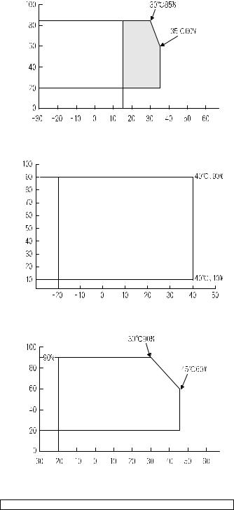
6. Environment conditions
(1) |
Space required |
|
Folded multi manual feed |
628 (W) × 585.5 (D) mm |
|
Open multi manual feed |
894 (W) × 585.5 (D) mm |
|
(2) |
Operating ambient conditions |
|
Humidity (%) |
Temperature (˚C)
(3) Ambient storage conditions
Humidity (%)
Temperature (˚C)
(4) Ambient conditions for transporting
Humidity (%) |
Temperature (˚C)
(5) Atmospheric pressure
595 mmHg or above
(6) Standard temperature and humidity
Temperature |
20 to 25°C |
Humidity |
65±5%RH |
7. IMC board functions
* Sort function |
32MB (Copy: 16MB, Print: 16MB) |
|
(Electronic sort) |
90 sheets (max. 1500 sheets) with A4 |
|
|
|
standard documents at 600dpi, 22 sheets |
|
|
(max. 726 sheets) with A4 standard |
|
|
documents at 1200dpi. Offset paper exit |
|
|
by the shifter function |
* Group function |
32MB (Copy: 16MB, Print: 16MB) |
|
|
|
90 sheets (max. 1500 sheets) with A4 |
|
|
standard documents at 600dpi, 22 sheets |
|
|
(max. 726 sheets) with A4 standard |
|
|
documents at 1200dpi. Offset paper exit |
|
|
by the shifter function |
Rotation copy |
If there is paper of the same size as the |
|
|
|
document size, the image is rotated and |
|
|
printed even though the paper is set in a |
|
|
different direction. (In some cases, |
|
|
enlargement rotation may not be executed.) |
2 in 1/4 in 1 |
Two pages or four pages of documents |
|
|
|
are copied on one page of paper. Division |
|
|
can be made with slid lines or dotted lines |
|
|
(by user setup). (The solid line width is 8 |
|
|
lines) |
Edge erase |
Images on the edges of the document are |
|
|
|
erased and copy is made. (Adjustable in |
|
|
the range of 0 – 20mm (0 – 1 inch).) |
Center erase |
The center image of the set document is |
|
|
|
erased and copy is made. (Adjustable in |
|
|
the range of 0 – 20mm (0 – 1 inch).) |
Binding edge |
Binding edge is provided on the left, right |
|
|
|
or the top of the set document. |
Compression memory |
32MB |
|
for electronic sort |
|
|
* Memory read |
600dpi |
32MB (Copy: 16MB, Print: 16MB) |
capacity |
|
90 sheets (Max. 1500 sheets) of A4 |
|
|
standard documents (Sharp A4 standard |
|
|
document Test Chart B (6%)) |
|
1200dpi |
22 sheets (Max. 726 sheets) of A4 |
|
|
standard documents (Sharp A4 standard |
|
|
document Test Chart B (6%)) |
Memory expansion |
2 slots for DIMM memory, Max. 512MB x 2 |
|
|
|
slots + 32MB (Expandable up to 1056MB) |
Note: The number of sheets for the columns marked with “*” is calculated supposing that the same quantity is assigned to the ROPM memory and the copy expansion memory.
8.“Sharp Printer Language with Compression (SPLC)” Printer function
A. Basic specification
Item |
Detail |
Print Speed |
15ppm: 600dpi (including transfer from PC) |
|
27ppm: ROPM (AR-M277/M276) |
|
23ppm: ROPM (AR-M237/M236) |
Resolution |
600dpi |
Smoothing |
1200dpi x 600dpi |
Toner Save Mode |
Standard |
Input tray |
Multi Bypass tray |
|
Tray 1, Tray 2, Tray 3, Tray 4 |
|
(Depending on conditions of the machine |
|
and option installation.) |
Duplex print |
Standard |
Finisher |
Option |
Printer driver |
Standard |
Manual (Online |
Standard |
manual) |
|
Platform |
IBM PC/AT (Include compatible machine) |
AR-M236/M276/M237/M277 SPECIFICATIONS 3 - 5
Item |
Detail |
Support OS (Printer |
Windows 95/98/Me |
Driver) |
Windows NT 4.0 Workstation (SP5 or later) |
|
Windows 2000 Professional |
|
Windows XP Home/Professional Edition |
B. Printer driver specification
(1) System
Machine |
OS |
|
IBM PC/AT |
Windows 95/98/Me |
|
(Include |
|
Windows NT 4.0 Workstation (SP5 or later) |
compatible |
|
Windows 2000 Professional |
machine) |
|
|
|
Windows XP Home/Professional Edition |
|
|
|
|
(2) Printing function specification
|
Function |
|
Content |
General |
Copies |
|
1-999 |
|
Orientation |
|
Portrait |
|
|
|
Landscape |
|
Collate |
|
Collate |
|
|
|
Uncollate |
|
Document Style |
|
1-Sided, 2-Sided (Book), |
|
|
|
2-Sided (Tablet) |
|
N-up printing |
|
2/4 |
|
N-up Order |
|
Z |
|
N-up Border |
|
Yes/No |
|
User Setting |
|
Yes |
Paper Input |
Paper Size |
|
A3 / B4 / A4 / B5 / A5 / B6 / |
|
|
|
A6 / Ledger (11x17) / |
|
|
|
Legal (8.5 x 14) / |
|
|
|
Foolscap (8.5 x 13) / |
|
|
|
Letter (8.5 x 11) / |
|
|
|
Invoice (5.5 x 8.5) / Folio / |
|
|
|
Executive / COM-10 / |
|
|
|
DL / C5 / 8K / 16K |
|
Custom Paper Size |
|
1 size |
|
Source Selection |
• |
Auto |
|
|
• |
Bypass (Auto) |
|
|
• |
Bypass (Manual) |
|
|
• |
Tray 1/2/3/4 |
|
Paper Type |
Tray: Normal paper, letter |
|
|
|
head paper, recycle paper, |
|
|
|
colored paper |
|
|
|
Bypass: Normal paper, letter |
|
|
|
head paper, recycle paper, |
|
|
|
colored paper, thick paper, |
|
|
|
thin paper, label paper, OHP, |
|
|
|
postcard, envelope |
|
|
Transparency print |
|
Yes / No |
Paper Output |
Output Tray Selection |
• |
Center Tray |
|
|
• |
Upper Tray |
|
|
• |
Finisher Offset tray |
|
Staple |
|
Yes / No |
Graphic |
Print Quality |
|
Normal |
|
|
|
Draft |
|
|
|
Photo |
|
Smoothing |
|
Yes / No |
|
Toner save |
|
Yes / No |
|
Photo Enhancement |
|
Yes / No |
|
Fit to Page |
|
Yes / No |
|
2 Gradation print |
|
Yes / No |
|
Image Adjustment |
|
Brightness : 0 to 100 |
|
|
|
Contrast : 0 to 100 |
|
Function |
Content |
Watermark |
Watermark |
(None) / TOP SECRET / |
|
|
CONFIDENTIAL / DRAFT / |
|
|
ORIGINAL / COPY |
|
User setting |
Add / Update / Delete |
|
Position |
Center |
|
|
X: ±50 |
|
|
Y : ±50 |
|
Size |
6 to 300 |
|
Angle |
±90 |
|
Gray Scale |
0 to 255 |
|
Edit Font |
Yes |
|
On first page only |
Yes / No |
Configuration |
Input Trays |
Two / Three / Four trays |
Setting |
Output Tray Options |
None / Upper Tray / Staple |
|
|
Finisher |
|
Set Tray Status |
Yes |
|
Version Information |
Yes |
Others |
ROPM |
Yes / No |
(3) Print quality
Mode |
Control |
Content |
Resolution/Print |
600dpi |
Print quality is selected from |
quality |
(Fixed) |
Normal*/Draft/Photo. |
Smoothing |
On* |
Smoothing function is ON. |
|
Off |
Smoothing function is OFF. |
Toner Save Mode |
On |
Toner save function is ON. |
|
Off* |
Toner save function is OFF. |
Photo Enhancement |
On |
Photo enhancement function is ON. |
|
Off* |
Photo enhancement function is |
|
|
OFF. |
2 Gradation print |
On |
2-Gradation print function is ON. |
|
Off* |
2-Gradation print function is OFF. |
* Default
AR-M236/M276/M237/M277 SPECIFICATIONS 3 - 6

(5) Paper handling specifications a. Paper feed direction
Limitations on tray/functions for support paper
|
|
|
|
|
|
|
|
|
|
|
|
|
|
|
|
|
|
|
Paper feed tray |
|
|
|
|
|
|
Paper exit tray |
|
|
|
|
Function |
|
||||||||||||
Paper name |
|
|
Paper size |
|
|
|
Manual |
|
Tray 1 |
|
Tray 2 |
Tray 3 |
|
Tray 4 |
|
Center |
Upper |
|
Offset |
|
|
Staple |
|
Fit page |
||||||||||||||||||||
|
|
|
|
|
|
|
|
|
|
|
|
|
tray |
|
|
|
|
|
|
tray |
|
tray |
|
|
tray |
|
|
|
||||||||||||||||
|
|
|
|
|
|
|
|
|
|
|
|
|
|
|
|
|
|
|
|
|
|
|
|
|
|
|
|
|
|
|
|
|
|
|
|
|
|
|||||||
A3 |
297 x 420 mm |
|
|
|
|
Yes |
|
|
|
Yes |
|
Yes |
Yes |
|
Yes |
|
Yes |
|
Yes |
|
|
Yes |
|
|
|
Yes |
|
Yes |
|
|||||||||||||||
A4 |
210 x 297 mm |
|
|
|
|
Yes |
|
|
|
Yes |
|
Yes |
Yes |
|
Yes |
|
Yes |
|
Yes |
|
|
Yes |
|
|
|
Yes |
|
Yes |
|
|||||||||||||||
A5 |
148 x 210 mm |
|
|
|
|
Yes |
|
|
|
Yes |
|
N/A |
N/A |
|
N/A |
|
Yes |
|
Yes |
|
|
N/A |
|
|
|
N/A |
|
Yes |
|
|||||||||||||||
A6 |
105 x 148 mm |
|
|
|
|
Yes |
|
|
|
N/A |
|
N/A |
N/A |
|
N/A |
|
Yes |
|
N/A |
|
|
N/A |
|
|
|
N/A |
|
Yes |
|
|||||||||||||||
B4 |
257 x 364 mm |
|
|
|
|
Yes |
|
|
|
Yes |
|
Yes |
Yes |
|
Yes |
|
Yes |
|
Yes |
|
|
Yes |
|
|
|
Yes |
|
Yes |
|
|||||||||||||||
B5 |
182 x 257 mm |
|
|
|
|
Yes |
|
|
|
Yes |
|
Yes |
Yes |
|
Yes |
|
Yes |
|
Yes |
|
|
Yes |
|
|
|
Yes |
|
Yes |
|
|||||||||||||||
B6 |
128 x 182 mm |
|
|
|
|
Yes |
|
|
|
N/A |
|
N/A |
N/A |
|
N/A |
|
Yes |
|
Yes |
|
|
N/A |
|
|
|
N/A |
|
Yes |
|
|||||||||||||||
Ledger |
11 x 17 inch |
|
|
|
|
Yes |
|
|
|
Yes |
|
Yes |
Yes |
|
Yes |
|
Yes |
|
Yes |
|
|
Yes |
|
|
|
Yes |
|
Yes |
|
|||||||||||||||
Letter |
8.5 x 11 inch |
|
|
|
|
Yes |
|
|
|
Yes |
|
Yes |
Yes |
|
Yes |
|
Yes |
|
Yes |
|
|
Yes |
|
|
|
Yes |
|
Yes |
|
|||||||||||||||
Legal |
8.5 x 14 inch |
|
|
|
|
Yes |
|
|
|
Yes |
|
Yes |
Yes |
|
Yes |
|
Yes |
|
Yes |
|
|
Yes |
|
|
|
Yes |
|
Yes |
|
|||||||||||||||
Executive |
7.25 x 10.5 inch |
|
|
|
|
Yes |
|
|
|
N/A |
|
N/A |
N/A |
|
N/A |
|
Yes |
|
Yes |
|
|
N/A |
|
|
|
N/A |
|
Yes |
|
|||||||||||||||
Folio |
8.3 x 13 inch |
|
|
|
|
Yes |
|
|
|
N/A |
|
N/A |
N/A |
|
N/A |
|
Yes |
|
Yes |
|
|
N/A |
|
|
|
N/A |
|
Yes |
|
|||||||||||||||
Invoice |
5.5 x 8.5 inch |
|
|
|
|
Yes |
|
|
|
Yes |
|
N/A |
N/A |
|
N/A |
|
Yes |
|
Yes |
|
|
N/A |
|
|
|
N/A |
|
Yes |
|
|||||||||||||||
Foolscap |
8.5 x 13 inch |
|
|
|
|
Yes |
|
|
|
Yes |
|
Yes |
Yes |
|
Yes |
|
Yes |
|
Yes |
|
|
Yes |
|
|
|
Yes |
|
Yes |
|
|||||||||||||||
8K |
270 x 390 mm |
|
|
|
|
Yes |
|
|
|
Yes |
|
Yes |
Yes |
|
Yes |
|
Yes |
|
Yes |
|
|
Yes |
|
|
|
N/A |
|
Yes |
|
|||||||||||||||
16K |
195 x 270 mm |
|
|
|
|
Yes |
|
|
|
Yes |
|
Yes |
Yes |
|
Yes |
|
Yes |
|
Yes |
|
|
Yes |
|
|
|
N/A |
|
Yes |
|
|||||||||||||||
DL |
110 x 220 mm |
|
|
|
|
Yes |
|
|
|
N/A |
|
N/A |
N/A |
|
N/A |
|
Yes |
|
Yes |
|
|
N/A |
|
|
|
N/A |
|
Yes |
|
|||||||||||||||
C5 |
162 x 229 mm |
|
|
|
|
Yes |
|
|
|
N/A |
|
N/A |
N/A |
|
N/A |
|
Yes |
|
Yes |
|
|
N/A |
|
|
|
N/A |
|
Yes |
|
|||||||||||||||
Com10 |
4.125 x 9.5 inch |
|
|
|
|
Yes |
|
|
|
N/A |
|
N/A |
N/A |
|
N/A |
|
Yes |
|
Yes |
|
|
N/A |
|
|
|
N/A |
|
Yes |
|
|||||||||||||||
Custom |
W: 100 to 297 mm |
|
|
|
Yes |
|
|
|
N/A |
|
N/A |
N/A |
|
N/A |
|
Yes |
|
N/A |
|
|
N/A |
|
|
|
N/A |
|
N/A |
|
||||||||||||||||
|
|
|
|
L: 148 to 431.8 mm |
|
|
|
|
|
|
|
|
|
|
|
|
|
|
|
|
|
|||||||||||||||||||||||
|
|
|
|
|
|
|
|
|
|
|
|
|
|
|
|
|
|
|
|
|
|
|
|
|
|
|
|
|
|
|
|
|
|
|
|
|
|
|
||||||
Setting direction toward paper |
Setting direction toward paper |
|
|
|
|
|
|
|
|
|
|
|
|
|
|
|
|
|
|
|
|
|||||||||||||||||||||||
|
Paper |
|
|
A |
|
|
B |
C |
|
D |
E |
|
F |
|
G |
|
H |
|||||||||||||||||||||||||||
|
feed port = Long side |
|
feed port = Short side |
|
|
|
Size |
|
|
|
|
|
|
|
|
|||||||||||||||||||||||||||||
|
|
|
|
|
|
|
|
|
|
|
|
|
|
|
|
|
|
|
|
|
|
|
||||||||||||||||||||||
|
|
Transfer direction |
|
Transfer direction |
|
|
|
A3 |
|
7014 |
|
9920 |
6730 |
|
142 |
100 |
|
300 |
6814 |
|
0 |
|||||||||||||||||||||||
|
|
|
|
|
|
B4 |
|
6070 |
|
8597 |
5786 |
|
142 |
100 |
|
300 |
5870 |
|
0 |
|||||||||||||||||||||||||
|
|
|
|
|
|
|
|
|
|
|
|
|
|
|
|
|
|
|
|
|
|
|
|
|
|
|
|
|
|
|||||||||||||||
|
|
|
|
|
|
|
|
|
|
|
|
|
|
|
|
|
|
|
|
|
|
|
|
|
|
|||||||||||||||||||
|
|
|
|
|
|
|
|
|
|
|
|
|
|
|
|
|
|
|
|
|
|
|
|
|
|
|
|
|
|
|
|
|
|
|
|
|
|
|
||||||
|
|
|
|
|
|
|
|
|
|
|
|
|
|
|
|
|
|
|
|
|
|
|
|
|
A4 |
|
4960 |
|
7014 |
4676 |
|
142 |
100 |
|
300 |
4760 |
|
0 |
||||||
|
|
|
|
|
|
|
|
|
|
|
|
|
|
|
|
|
|
|
|
|
|
|
|
|
|
|||||||||||||||||||
|
|
|
|
|
|
|
|
|
|
|
|
|
|
|
|
|
|
|
|
|
|
|
|
|
B5 |
|
4298 |
|
6070 |
5770 |
|
142 |
100 |
|
300 |
4098 |
|
0 |
||||||
|
|
|
|
|
|
|
|
|
|
|
|
|
|
|
|
|
|
|
|
|
|
|
|
|
|
|||||||||||||||||||
|
|
|
|
|
|
|
|
|
|
|
|
|
|
|
|
|
|
|
|
|
|
|
|
|
A5 |
|
3508 |
|
4960 |
3224 |
|
142 |
100 |
|
300 |
3308 |
|
0 |
||||||
|
|
|
|
|
|
|
|
|
|
|
|
|
|
|
|
|
|
|
|
|
|
|
|
|
|
|||||||||||||||||||
|
|
|
|
|
|
|
|
|
|
|
|
|
|
|
|
|
|
|
|
|
|
|
|
|
|
|||||||||||||||||||
|
|
|
|
|
|
|
|
|
|
|
|
|
|
|
|
|
|
|
|
|
|
|
|
Ledger |
|
6600 |
|
10200 |
6300 |
|
150 |
100 |
|
300 |
6400 |
|
0 |
|||||||
|
|
|
|
|
|
|
|
|
|
|
|
|
|
|
|
|
|
|
|
|
|
|
|
|||||||||||||||||||||
|
|
|
|
|
|
|
|
|
|
|
|
|
|
|
|
|
|
|
|
|
|
|
|
Legal |
|
5100 |
|
8400 |
4800 |
|
150 |
100 |
|
300 |
4900 |
|
0 |
|||||||
|
|
|
|
|
|
|
|
|
|
|
|
|
|
|
|
|
|
|
|
|
|
|
|
|||||||||||||||||||||
|
|
|
|
|
|
|
|
|
|
|
|
|
|
|
|
|
|
|
|
|
|
|
|
Letter |
|
5100 |
|
6600 |
4800 |
|
150 |
100 |
|
300 |
4900 |
|
0 |
|||||||
|
|
|
|
|
|
|
|
|
|
|
|
|
|
|
|
|
|
|
|
|
|
|
|
|||||||||||||||||||||
|
|
|
|
|
|
|
|
|
|
|
|
|
|
|
|
|
|
|
|
|
|
|
|
Invoice |
|
3300 |
|
5100 |
3000 |
|
150 |
100 |
|
300 |
3100 |
|
0 |
|||||||
|
|
|
|
|
|
|
|
|
|
|
|
|
|
|
|
|
|
|
|
|
|
|
|
|||||||||||||||||||||
|
|
|
|
|
|
|
|
|
|
|
|
|
|
|
|
|
|
|
|
|
|
|
|
Foolscap |
|
5100 |
|
7800 |
4800 |
|
150 |
100 |
|
300 |
4900 |
|
0 |
|||||||
|
|
|
|
|
|
|
|
|
|
|
|
|
|
|
|
|
|
|
|
|
|
|
|
|||||||||||||||||||||
|
|
|
|
|
|
|
|
|
|
|
|
|
|
|
|
|
|
|
|
|
|
|
|
|
Folio |
|
4980 |
|
7800 |
4680 |
|
150 |
100 |
|
300 |
4780 |
|
0 |
||||||
|
|
|
|
|
|
|
|
|
|
|
|
|
|
|
|
|
|
|
|
|
|
|
|
|
|
|||||||||||||||||||
(6) Print enable area |
|
|
|
|
|
|
|
|
|
|
|
|
|
|
|
Executive |
|
4350 |
|
6300 |
4050 |
|
150 |
100 |
|
300 |
4150 |
|
0 |
|||||||||||||||
|
|
|
|
|
|
|
|
|
|
|
|
|
|
|
COM-10 |
|
2474 |
|
5700 |
2174 |
|
150 |
100 |
|
300 |
2274 |
|
0 |
||||||||||||||||
|
|
|
|
|
|
|
|
|
|
|
|
|
|
|
|
|
|
|
|
|
|
|
|
|
|
|
|
|
||||||||||||||||
|
|
|
|
|
|
|
|
|
|
|
|
|
|
|
|
|
|
|
|
|
|
|
|
|
C5 |
|
3826 |
|
5408 |
3542 |
|
142 |
100 |
|
300 |
3626 |
|
0 |
||||||
|
|
|
|
|
|
|
|
|
|
|
|
|
|
|
Actual page size |
|
|
DL |
|
2598 |
|
5196 |
2314 |
|
142 |
100 |
|
300 |
2398 |
|
0 |
|||||||||||||
|
|
|
|
|
|
|
|
|
|
|
|
|
|
|
|
|
|
|||||||||||||||||||||||||||
|
|
|
|
|
|
|
|
|
|
|
|
|
|
|
Print area |
|
|
|
|
|
|
|
|
|
|
|
|
|
|
|
|
|
|
|
|
|
|
|
||||||
|
|
|
|
|
|
|
|
|
|
|
|
|
|
|
|
|
|
|
|
|
|
|
|
|
|
|
|
|
|
|
|
|
|
|
|
|
|
|||||||
|
|
|
|
|
|
|
|
|
|
|
|
|
|
|
Logic paper size |
|
|
|
|
|
|
|
|
|
|
|
|
|
|
|
|
|
|
|
|
|
|
|||||||
|
|
|
|
|
|
|
|
|
|
|
|
|
|
|
|
|
|
|
|
|
|
|
|
|
|
|
|
|
|
|
|
|
|
|
|
|
||||||||
|
|
|
|
|
|
|
|
|
|
|
|
|
|
|
HP/GL |
|
|
|
|
|
|
|
|
|
|
|
|
|
|
|
|
|
|
|
|
|
|
|
||||||
|
|
|
|
|
|
|
|
|
|
|
|
|
|
|
|
|
|
|
|
|
|
|
|
|
|
|
|
|
|
|
|
|
|
|
|
|
|
|||||||
|
|
|
|
|
|
|
|
|
|
|
|
|
|
|
picture frame |
|
|
|
|
|
|
|
|
|
|
|
|
|
|
|
|
|
|
|
|
|
|
|
||||||
|
|
|
|
|
|
|
|
|
|
|
|
|
|
|
|
|
|
|
|
|
|
|
|
|
|
|
|
|
|
|
|
|
|
|
|
|
|
|
|
|
|
|
|
|
|
|
|
|
|
|
|
|
|
|
|
|
|
|
|
|
|
|
|
|
|
|
|
|
|
|
|
|
|
|
|
|
|
|
|
|
|
|
|
|
|
|
|
|
|
|
|
|
|
|
|
|
|
|
|
|
|
|
|
|
|
|
|
|
|
|
|
|
|
|
|
|
|
|
|
|
|
|
|
|
|
|
|
|
|
|
|
|
|
|
AR-M236/M276/M237/M277 SPECIFICATIONS 3 - 7
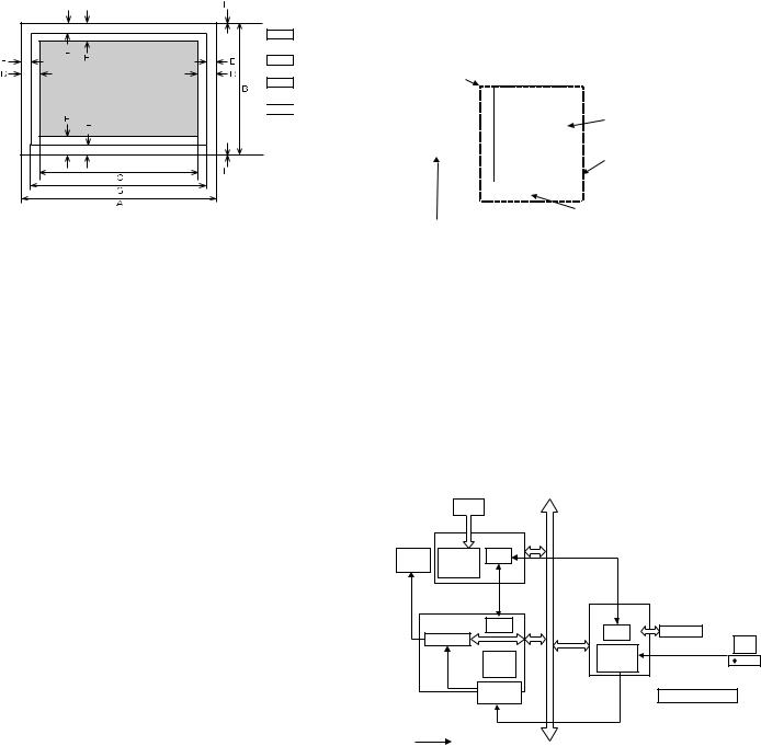
Actual page size
Print area
Logic paper size

 HP/GL picture frame
Paper |
A |
B |
C |
D |
E |
F |
G |
H |
|
Size |
|||||||||
|
|
|
|
|
|
|
|
||
A3 |
9920 |
7014 |
9684 |
118 |
100 |
300 |
9720 |
0 |
|
B4 |
8597 |
6070 |
8361 |
118 |
100 |
300 |
8397 |
0 |
|
A4 |
7014 |
4960 |
6778 |
118 |
100 |
300 |
6814 |
0 |
|
B5 |
6070 |
4298 |
5830 |
118 |
100 |
300 |
5870 |
0 |
|
A5 |
4960 |
3508 |
4720 |
118 |
100 |
300 |
4760 |
0 |
|
Ledger |
8400 |
5100 |
8160 |
120 |
100 |
300 |
8200 |
0 |
|
Legal |
8400 |
5100 |
8160 |
120 |
100 |
300 |
8200 |
0 |
|
Letter |
6600 |
5100 |
6360 |
120 |
100 |
300 |
6400 |
0 |
|
Invoice |
5100 |
3300 |
2860 |
120 |
100 |
300 |
4900 |
0 |
|
Foolscap |
7800 |
5100 |
7560 |
120 |
100 |
300 |
7600 |
0 |
|
Folio |
7800 |
4980 |
7560 |
120 |
100 |
300 |
7600 |
0 |
|
Executive |
6300 |
4350 |
6060 |
120 |
100 |
300 |
6100 |
0 |
|
COM-10 |
5700 |
2474 |
3460 |
120 |
100 |
300 |
5500 |
0 |
|
C5 |
5408 |
3826 |
5172 |
118 |
100 |
300 |
5208 |
0 |
|
DL |
5196 |
2598 |
4960 |
118 |
100 |
300 |
4996 |
0 |
Top margin
The set value is received from the digital copier, and data are made according to the set value.
Left margin
Since the paper size sensor is not set, the digital copier cannot recognize the size and direction of paper which is actually inserted. Therefore, the left margin is set according to the paper size specified in the print data sent from the computer, and print process is performed. If the computer does not specify the paper size, or in the case of the custom size, the left margin is set according to the default paper size.
(7) Print reference
This machine employs the center reference system.
Since the digital copier is not provided with the tray size detection feature, formatting and center distribution are performed not by the actual paper size but by the paper size specified by the computer.
|
Origin |
|
|
|
|
|
|
|
|
|
|
|
|
|
|
|
ABCDEFGHIJKLMN |
|
|
|
|
|
|
|
|
|
|
|
|
|
|
|
|
|
|
|
||
directionfeed |
12345 |
|
|
|
Actual paper size |
|
||||||
abc |
|
|
|
|
|
|
|
|||||
|
|
|
|
|
|
|
||||||
|
|
|
|
|
|
|
|
|
|
|
|
|
|
|
|
|
|
|
|
|
Size specified by the HOST |
|
|||
Paper |
|
|
|
|
|
|
|
|
|
|
||
|
|
|
|
|
|
|
|
|
|
|||
|
|
|
|
|
|
|
|
|
|
|||
|
|
|
|
Center reference line |
|
|
|
|||||
|
|
|
|
|
|
|
|
|
|
|||
C. Interface |
|
|
|
|
|
|
|
|
|
|
||
|
|
|
|
|
|
|
|
|
|
|||
|
|
|
|
|
|
|
|
|
|
|
|
|
Interface |
|
|
IEEE 1284 (Parallel interface) |
|||||||||
|
|
|
|
|
USB Ver. 2.0 |
|
|
|
|
|
|
|
D. System outline
The GDI-PWB is provided with IEEE1284 I/F on the host side, and the 16-bit bi-directional data bus I/F and UART on the machine side. Transfer of image data with the IMC-PWB is performed with this 16-bit bi-directional data bus. Command status information with the engine is processed with UART.
This unit is installed to the position of PCL-PWB on the conventional AR-235/275.
JBIG compression data sent from the host are transferred to the IMC PWB, where the data are extracted to be VIDEO data, and sent through the MCU PWB to the LSU.
|
|
|
M-bus |
|
|
|
CCD |
|
|
|
|
|
MCU |
|
UART |
|
|
Image |
CPU |
Command status |
|
||
Engine |
process |
|
|
|
|
|
ASIC |
|
|
|
|
IMC |
|
JBIG |
GDI |
|
|
CPU |
CPU |
IEEE1284 |
|||
Page memory |
|
data |
|||
|
|
|
Header + JBIG data PC |
||
|
|
JBIG- |
|
ASIC |
|
|
|
|
|
||
|
Extraction |
Lite |
|
|
|
|
|
|
|
|
|
|
Compressed |
|
|
JBIG printer driver |
|
|
|
memory |
|
|
|
|
|
|
Data through |
|
|
|
: Data flow |
|
|
|
|
AR-M236/M276/M237/M277 SPECIFICATIONS 3 - 8
[4] CONSUMABLE PARTS
1. |
List |
|
|
|
|
|
|
A. SEC/LAG/SECL |
|
|
|
|
|
|
|
|
|
|
|
|
|
|
|
No. |
Item |
Content |
|
Life |
Model name |
|
Remarks |
1 |
Toner CA (black) w/IC |
Toner |
×10 |
25K (×10) |
AR-270MT |
Life setting by A4 (8.5"×11") 6% document |
|
|
|
Vinyl bag |
×10 |
|
|
MT=NT*10 |
|
2 |
Developer |
Developer |
×10 |
75K (×10) |
AR-271MD |
MD=ND*10 |
|
|
|
(Developer; Net weight 500g) |
|
|
|
|
|
3 |
Drum kit |
Drum |
×1 |
75K |
AR-271DR |
|
|
4 |
Upper heat roller kit |
Upper heat roller |
×1 |
150K |
AR-272UH |
|
|
|
|
Fusing gear |
×1 |
|
|
|
|
|
|
Upper heat roller bearing |
×2 |
|
|
|
|
|
|
Upper cleaning pad |
×1 |
|
|
|
|
|
|
Fusing separation pawl (upper) |
×4 |
|
|
|
|
5 |
Lower heat roller kit |
Lower heat roller |
×1 |
300K |
AR-272LH |
|
|
|
|
Fusing separation pawl (lower) |
×4 |
|
|
|
|
|
|
Fusing busing (lower) |
×2 |
|
|
|
|
6 |
150K maintenance kit |
Drum separation unit |
×2 |
150K |
AR-272KA1 |
|
|
|
|
Transfer roller unit |
×1 |
|
|
|
|
|
|
DV seal |
×1 |
|
|
|
|
|
|
DV side sheet N |
×1 |
|
|
|
|
|
|
DV side sheet N2 |
×1 |
|
|
|
|
|
|
DV side mylar |
×2 |
|
|
|
|
7 |
MC unit |
MC unit |
×10 |
75K (×10) |
AR-270MC |
|
|
8 |
Cleaner blade |
Cleaner blade |
×10 |
75K (×10) |
AR-270CB |
|
|
9 |
Drum frame unit |
Drum frame unit |
×1 |
225K |
AR-272DU |
|
The life of the toner reception seat welded to the |
|
|
|
|
|
|
|
drum frame is 225K, and it can be used up to 3 |
|
|
|
|
|
|
|
times. (Supplied as a drum frame unit.) |
|
|
|
|
|
|
|
Drum frame unit contains all the drum unit parts |
|
|
|
|
|
|
|
excluding Drum and Drum fixing plate. |
10 |
Staple cartridge |
Staple cartridge |
×3 |
3000 staples |
AR-SC1 |
For AR-FN5N (For 30 sheets staple) |
|
|
|
|
|
×3 |
|
|
|
11 |
Transfer roller unit |
Transfer roller unit |
×1 |
150K |
AR-272TX |
|
|
12 |
Paper feed roller kit |
Paper feed roller kit |
×1 |
100K |
AR-271IR |
|
|
13 |
Fusing unit |
Fusing unit (120V heater lamp) |
×1 |
150K |
AR-272FU |
|
|
The other maintenance parts than the above are supplied as service parts. |
|
|
|
||||
B. SEEG/SUK/SCA/SCNZ/SEA/SEES/SEZ/SEIS/SEB/SEN/SEF/SMEF/Russia/Special country |
|||||||
|
|
|
|
|
|
|
|
No. |
Item |
Content |
|
Life |
Model name |
|
Remarks |
1 |
Toner CA (black) w/IC |
Toner |
×10 |
25K (×10) |
AR-270LT |
Life setting by A4 (8.5"×11") 6% document |
|
|
|
Vinyl bag |
×10 |
|
|
LT=T*10 |
|
2 |
Developer |
Developer |
×10 |
75K (×10) |
AR-271LD |
LD=DV*10 |
|
|
|
(Developer; Net weight 500g) |
|
|
|
|
|
3 |
Drum kit |
Drum |
×1 |
75K |
AR-271DM |
|
|
4 |
Upper heat roller kit |
Upper heat roller |
×1 |
150K |
AR-272UH |
|
|
|
|
Fusing gear |
×1 |
|
|
|
|
|
|
Upper heat roller bearing |
×2 |
|
|
|
|
|
|
Upper cleaning pad |
×1 |
|
|
|
|
|
|
Fusing separation pawl (upper) |
×4 |
|
|
|
|
5 |
Lower heat roller kit |
Lower heat roller |
×1 |
300K |
AR-272LH |
|
|
|
|
Fusing separation pawl (lower) |
×4 |
|
|
|
|
|
|
Fusing busing (lower) |
×2 |
|
|
|
|
6 |
150K PM kit |
Drum separation unit |
×2 |
150K |
AR-272KA |
|
|
|
|
Transfer roller unit |
×1 |
|
|
|
|
|
|
DV seal |
×1 |
|
|
|
|
|
|
DV side sheet N |
×1 |
|
|
|
|
|
|
DV side sheet N2 |
×1 |
|
|
|
|
|
|
DV side mylar |
×2 |
|
|
|
|
7 |
MC unit |
MC unit |
×10 |
75K (×10) |
AR-270MC |
|
|
8 |
Cleaner blade |
Cleaner blade |
×10 |
75K (×10) |
AR-270CB |
|
|
9 |
Drum frame unit |
Drum frame unit |
×1 |
225K |
AR-272DU |
|
The life of the toner reception seat welded to the |
|
|
|
|
|
|
|
drum frame is 225K, and it can be used up to 3 |
|
|
|
|
|
|
|
times. (Supplied as a drum frame unit.) |
|
|
|
|
|
|
|
Drum frame unit contains all the drum unit parts |
|
|
|
|
|
|
|
excluding Drum and Drum fixing plate. |
10 |
Staple cartridge |
Staple cartridge |
×3 |
3000 staples |
AR-SC1 |
For AR-FN5N (For 30 sheets staple) |
|
|
|
|
|
×3 |
|
|
|
11 |
Transfer roller unit |
Transfer roller unit |
×1 |
150K |
AR-272TX |
|
|
The other maintenance parts than the above are supplied as service parts.
AR-M236/M276/M237/M277 CONSUMABLE PARTS 4 - 1
C. STCL/SRH/SRS/SRSSC/SBI/Agent
No. |
Item |
Content |
|
Life |
Model name |
|
Remarks |
|
|
|
|
|
|
|
|
1 |
Toner CA (black) w/IC |
Toner |
×10 |
25K (×10) |
AR-270CT |
Life setting by A4 (8.5"×11") 6% document |
|
|
|
Vinyl bag |
×10 |
|
|
CT=ST*10 |
|
|
|
|
|
|
|
|
|
2 |
Developer |
Developer |
×10 |
75K (×10) |
AR-271CD |
CD=SD*10 |
|
|
|
(Developer; Net weight 500g) |
|
|
|
|
|
|
|
|
|
|
|
|
|
3 |
Drum kit |
Drum |
×1 |
75K |
AR-271DR |
|
|
|
|
|
|
|
|
|
|
4 |
Upper heat roller kit |
Upper heat roller |
×1 |
150K |
AR-272UH |
|
|
|
|
Fusing gear |
×1 |
|
|
|
|
|
|
Upper heat roller bearing |
×2 |
|
|
|
|
|
|
Upper cleaning pad |
×1 |
|
|
|
|
|
|
Fusing separation pawl (upper) |
×4 |
|
|
|
|
|
|
|
|
|
|
|
|
5 |
Lower heat roller kit |
Lower heat roller |
×1 |
300K |
AR-272LH |
|
|
|
|
Fusing separation pawl (lower) |
×4 |
|
|
|
|
|
|
Fusing busing (lower) |
×2 |
|
|
|
|
|
|
|
|
|
|
|
|
6 |
150K PM kit |
Drum separation unit |
×2 |
150K |
AR-272KA |
|
|
|
|
Transfer roller unit |
×1 |
|
|
|
|
|
|
DV seal |
×1 |
|
|
|
|
|
|
DV side sheet N |
×1 |
|
|
|
|
|
|
DV side sheet N2 |
×1 |
|
|
|
|
|
|
DV side mylar |
×2 |
|
|
|
|
|
|
|
|
|
|
|
|
7 |
MC unit |
MC unit |
×10 |
75K (×10) |
AR-270MC |
|
|
|
|
|
|
|
|
|
|
8 |
Cleaner blade |
Cleaner blade |
×10 |
75K (×10) |
AR-270CB |
|
|
|
|
|
|
|
|
|
|
9 |
Drum frame unit |
Drum frame unit |
×1 |
225K |
AR-272DU |
|
The life of the toner reception seat welded to the |
|
|
|
|
|
|
|
drum frame is 225K, and it can be used up to 3 |
|
|
|
|
|
|
|
times. (Supplied as a drum frame unit.) |
|
|
|
|
|
|
|
Drum frame unit contains all the drum unit parts |
|
|
|
|
|
|
|
excluding Drum and Drum fixing plate. |
|
|
|
|
|
|
|
|
10 |
Staple cartridge |
Staple cartridge |
×3 |
3000 staples |
AR-SC1 |
For AR-FN5N (For 30 sheets staple) |
|
|
|
|
|
×3 |
|
|
|
|
|
|
|
|
|
|
|
The other maintenance parts than the above are supplied as service parts.
AR-M236/M276/M237/M277 CONSUMABLE PARTS 4 - 2

2. Production number identification
<TD cartridge>
The label on the TD cartridge shows the date of production.
Serial number |
Production |
||
(0001-9999) |
month |
|
|
Unit version |
January |
1 |
|
~ |
~ |
||
Destination |
September |
9 |
|
October |
0 |
||
|
|||
The end digit of |
November |
X |
|
production year |
December |
Y |
|
3. Environment conditions
A. Ambient conditions for transporting
Humidity (%) |
Temperature (˚C)
B. Ambient storage conditions (sealed)
Label position
<Drum>
The laser print indicates the date (year, month, day) of production.
1 |
2 |
3 |
|
|
|
1The last digit of the production year.
2The production month.
X stands for October, Y November, and Z December.
3The production sub lot.
Humidity (%)
Temperature (˚C)
C. Operating ambient conditions
(%) |
|
|
|
|
|
Use envi- |
|||||
|
|
|
|
|
|||||||
|
|||||||||||
Humidity |
|
|
|
|
|
ronment |
|||||
|
|
|
|
|
conditions |
||||||
|
|
|
|
|
|
|
|
|
|
|
|
|
|
|
|
|
|
|
|
|
|
|
|
|
|
|
|
|
|
|
|
|
|
|
|
Temperature (˚C)
4. Life (packed conditions)
Photoconductor drum (36 months from the production month) Developer, toner (24 months from the production month)
AR-M236/M276/M237/M277 CONSUMABLE PARTS 4 - 3
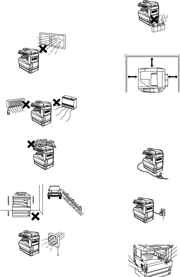
[5] UNPACKING AND INSTALLATION
1. Installation
A. Environment
The performance of this machine is affected by the environment of the installing site. Avoid installation to the following places:
•Avoid installation in direct sunlight, otherwise the plastic parts may be deformed.
•Avoid installation in a place of high temperature, high humidity, low temperature or low humidity, otherwise paper may be dampened and frost may be generated in the machine to cause a paper jam and dirty copy.
•Avoid installation in a dusty place, otherwise dust may enter the machine to cause dirty copy or machine troubles.
•Avoid installation to a place with much vibration, otherwise the machine may cause troubles.
• Avoid installation to a place of poor ventilation.
•Avoid installation to a place where there is ammonium gas. Installation near a diazo-copier may lead to dirty copy.
•Be sure to have enough space around the machine.
Be sure to allow the required space around the machine for servicing and proper ventilation.
|
12" (30cm) |
12" |
12" |
(30cm) |
(30cm) |
B. Power source
•Be sure to use only the power outlet (with the earth terminal) of 15A or more and 100V.
•Install the machine near the power outlet to facilitate disconnection of the power plug.
•If the power plug of this machine and other illuminating apparatus are connected to the same power outlet, the lamp may flicker. Use an exclusive power outlet for this machine without connecting another lamp together.
•Avoid complex wiring. Be careful not to damage, break, or process the power cord.
•Earth wire connection
Be sure to connect the earth wire for protection against danger. If not, a leakage may cause a fire or an electric shock.
Earth terminal
C. Transport
•When transporting the machine, use manpower of two persons to hold the grips on the both sides of the machine with both hands.
AR-M236/M276/M237/M277 UNPACKING AND INSTALLATION 5 - 1
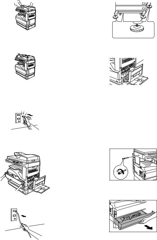
D. Other precautions
•If the machine produces smoke or bad smell, stop the operation of the machine.
•Do not use flammable spray near the machine.
•Do not remove the cabinet of the machine.
•Do not put a receptacle with water in it or metal pieces, which may drop inside the machine, causing a trouble.
•When it thunders, turn off the power and disconnect the power plug from the power outlet to prevent against an electric shock or a fire caused by lighting damage.
•If a piece of metal or water enters the machine, turn off the power and disconnect the power plug from the power outlet.
•Do not touch the power plug with a wet hand.
•Do not remodel the machine.
•Be careful not to pinch your fingers when closing the front cover or the side cover and setting the paper feed tray to supply paper or process a paper jam.
•When disconnecting the power plug from the power outlet, do not pull the cord.
•Do not throw toner or the toner cartridge into a fire.
•Keep toner or the toner cartridge away from the children.
•When the exclusive table (option) is used, be sure to use the adjusters (4 pcs.) on the floor.
When it is required to move the machine for rearrangement of the office, etc., release the adjuster locks and move the machine.
Adjuster 
Lock  Release
•The fusing section is heated to a high temperature.
When removing a paper jam, be careful not to touch the fusing section.
Fusing section
•When the machine is not used for a long time, disconnect the power plug from the power outlet for safety.
•When transporting the machine, turn off the power and disconnect the power plug from the power outlet. (Remove the earth wire after disconnecting the power plug from the power outlet.)
2.Removal of protective material and fixing screw
1)Remove all tapes, then open the document cover and remove the protective material of sheet shape.
2)Use a screwdriver to remove the fixing screw.
The fixing screw is required when transporting the machine. Keep it in the tray. (Refer to the later description.)
3. Removal and storage of fixing pin
1) Lift the knob and gently pull out the tray.
AR-M236/M276/M237/M277 UNPACKING AND INSTALLATION 5 - 2
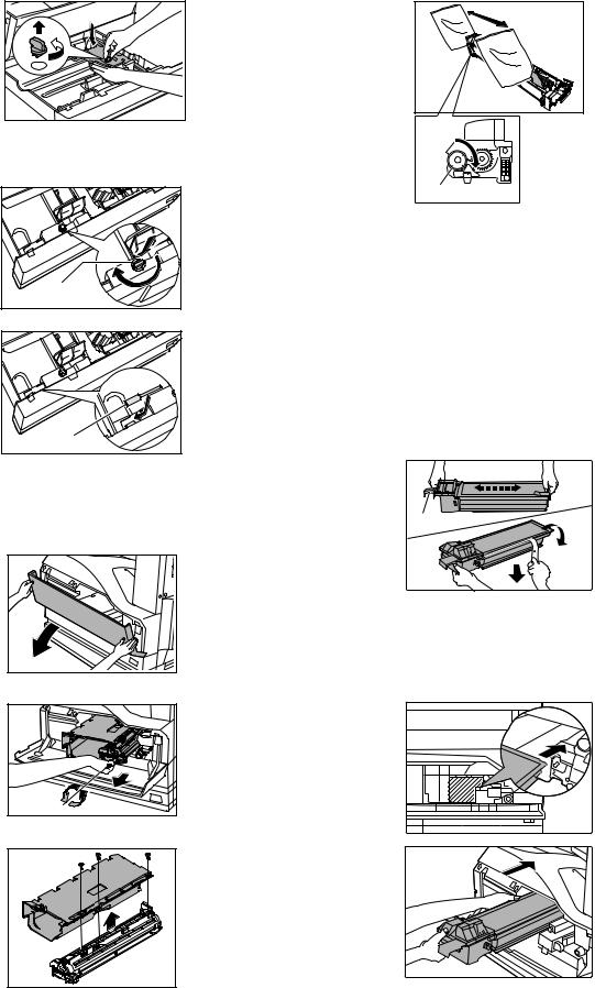
2)Hold the paper pressure plate and turn the fixing pin in the arrow direction.
4)Rotate the MG roller in the arrow direction and supply developer evenly into the developing unit.
3)Store the removed fixing pin and the fixing screw which was removed in the above procedure, together in the specified storage place in the tray.
Fixing pin |
Fixing screw |
If power is turned don without removing the fixing pin, it will be difficult to pull out the tray.
4. Developer cartridge installation
1) Hold the both sides of the front cover, and pull down to open it.
2) Loosen the blue screw and pull out the developing cartridge.
3) Remove the developer tank from the developer cartridge.
MG roller
Shake the developer bag enough before opening it.
Check that the DV seal is free from developer. If developer is attached to the DV seal, clean and remove it.
5)Attach the developer tank to the developer cartridge.
After supplying developer into the developer cartridge, do not tilt or shake the developer cartridge.
6)Attach the developer cartridge to the copier, and fix it with the screw.
Note: When replacing the OPC drum with a new one, be sure to clear the drum count.
5. Toner cartridge installation
1)Remove the toner cartridge from the bag, shake it about 20 times horizontally, and remove the tape.
Shake about 20 times.
Shutter
 Tape
Tape
When holding the toner cartridge, do not touch the shutter section, but hold the grips. Do not remove the tape before shaking the cartridge.
2)Press the lock release lever, and insert the unit completely into the copier along the guide groove. Then fix the blue screw and the locking screw.
Dirt or dust must be removed from the toner cartridge before installing.
AR-M236/M276/M237/M277 UNPACKING AND INSTALLATION 5 - 3
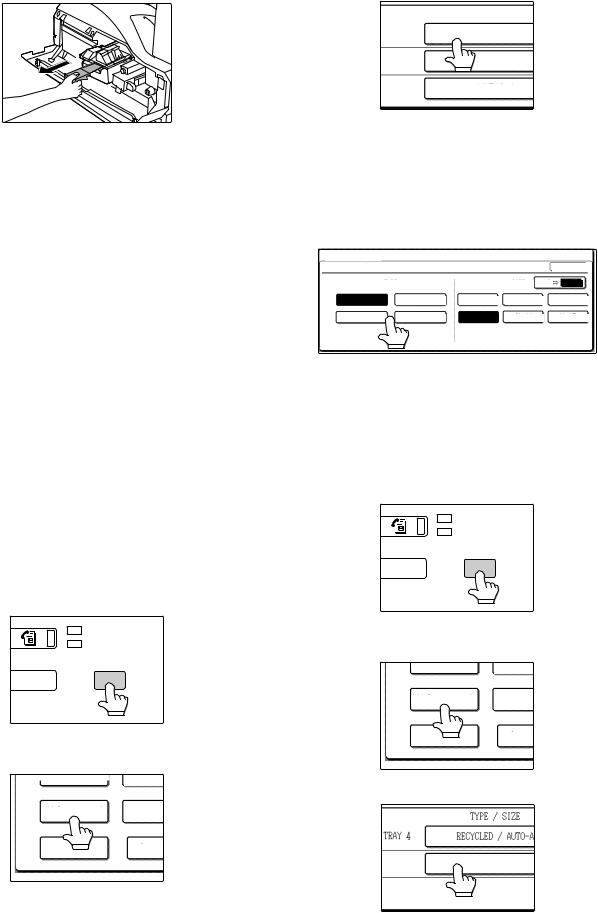
3)Remove the tape from the shutter, and remove the shutter from the toner cartridge.
Dispose the removed shutter.
6. Toner density sensor level adjustment
1)Open the cover with the power OFF.
2)Power ON (The mechanism cannot be initialized because the cover is open.)
3)Install the developing unit with new developer in it.
4)Enter SIM 25-2.
(# → → C → → 25 → START → 2 → START)
5)Close the cover immediately before starting the operation.
6)Press the [START] key to start.
After completion of the adjustment, be sure to cancel the simulation.
Note: When replacing developer with new one, be sure to clear the developer counter.
7. Tray paper size setting
When the tray paper size is changed, set the tray paper size in the following procedure.
During temporary halt due to paper empty or a paper jam or during interruption copy, the paper size setting cannot be made.
During FAX data output (when the FAX function is provided) or during printing (when the printing function is provided), the paper size setting cannot be made even in the copy mode.
Note: A5 (5 1/2" x 8 1/2") size paper can be set only to the first tray and the manual feed tray.
B5 size paper cannot be set to the second tray. (B5R size paper can be set.)
A. Trays 1 – 4
1)Set paper on the tray.
2)Press the [CUSTOM SETTINGS] key.
The custom settings menu screen will appear.
LINE
DATA
B STATUS CUSTOM SETTINGS
3)Touch the [TRAY SETTINGS] key. The tray settings screen will appear.
TOT L COUNT
CONTRA
TRAY SETTINGS
ADDRE
CONTR
KEY
SELECT
4)Select the tray in which you loaded paper.
If the desired tray does not appear in the display, use the [↑] key or [↓] key to scroll until it appears.
|
|
TYPE / SIZE |
|
TRAY 1 |
PLAIN / 8½ x |
11 |
|
TRAY |
2 |
PLAIN / 8½ x |
14 |
TRAY |
3 |
PLAIN / 11x17 |
|
5)Select the size and type of paper that is loaded in the tray. The currently selected paper type will be highlighted.
•To change the paper type selection, touch the appropriate type key.
•To change the paper size selection, touch the appropriate size key.
•To change the displayed size selections to AB sizes, touch [AB ↔ INCH].
CUSTOM |
SETTINGS |
|
|
|
|
|
TRAY 1 |
TYPE/SIZE SETTING |
|
|
|
OK |
|
|
|
TYPE |
|
SIZE |
AB |
INCH |
|
PLAIN |
LETTER HEAD |
11x17 |
8½x14 |
|
8½x13 |
|
RECYCLED |
COLOR |
8½x11 |
8½x11R |
|
5½x8½ |
6)Touch the [OK] key.
7)A message appears prompting you to check the paper in the tray. Check the paper and then touch the [OK] key.
You will return to the tray settings screen.
B. Manual feed tray
1)Set paper on the tray.
2)Press the [CUSTOM SETTINGS] key.
The custom settings menu screen will appear.
LINE
DATA
B STATUS CUSTOM SETTINGS
3)Touch the [TRAY SETTINGS] key. The tray settings screen will appear.
TOT L COUNT
CONTRA
TRAY SETTINGS
ADDRE
CONTR
KEY
SELECT
4) Touch the [BYPASS TRAY] key.
|
|
|
TYPE / SIZE |
|
|
|
|
|
|
TRAY 4 |
|
|
PLAIN / 11x17 |
|
BYPASS |
PLAIN |
|
TRAY |
||
|
AR-M236/M276/M237/M277 UNPACKING AND INSTALLATION 5 - 4
5)Select the type of paper that is loaded in the tray. Touch the appropriate paper type key.
CUSTOM SETTINGS |
|
|
|
BYPASS TRAY TYPE SETTING |
|
OK |
|
SELECT THE PAPER TYPE. |
|
|
|
PLAIN |
LETTER HEAD |
ENVELOPE |
JAPANESE P/C |
RECYCLED |
COLOR |
LABELS |
|
HEAVY PAPER |
THIN PAPER |
TRANSPARENCY |
|
6)Touch the [OK] key.
You will return to the tray settings screen.
8. Installation of options
A. AR-P17
(1) Parts included
|
|
|
CD-ROM: 1 pc. |
|
|
|
|
Operation manual |
|
|
|
|
Installation caution |
|
|
|
|
sheet |
|
PCL PWB: 1 pc. |
|
|
||
M3 screws: 3 pcs. |
M3 screws with |
|
||
(For installation of |
spring washer: |
6 pcs. |
Support post: 2 pcs. |
|
the parallel and the |
(For installation of the |
|||
|
||||
USB connectors) |
PCL PWB) |
|
||
(2) Installation procedure
Turn off the main switch of the copier and then remove the power plug of the copier from the outlet.
1)Remove the shielding plate.
Remove five screws and remove the shielding plate.
Screws
Screws 
2)Cut and remove the cut-out portion from the left rear cabinet.
Cut and remove the cut-out portion from the left rear cabinet using a tool such as nippers. (Be careful about the direction of the tool so that the cut surface is flat.)
Cut-out portion
3) Attach the PCL PWB unit.
Attach the support post to the mounting plate of machine options. Then connect the PCL PWB connector to the mother board connector and fit the PCL PWB with the six screws with M3 spring washer (packed with the unit).
Then, attach the parallel and USB connector portion using the supplied three screws.
M3 screws with |
M3 screw |
|
spring washer |
||
Support |
||
|
post |
|
|
M3 screws |
PCL PWB
M3 screws with spring washer
4)Attach the shielding plate.
Attach the shielding plate using five screws.
Screws 
Screws 
AR-M236/M276/M237/M277 UNPACKING AND INSTALLATION 5 - 5
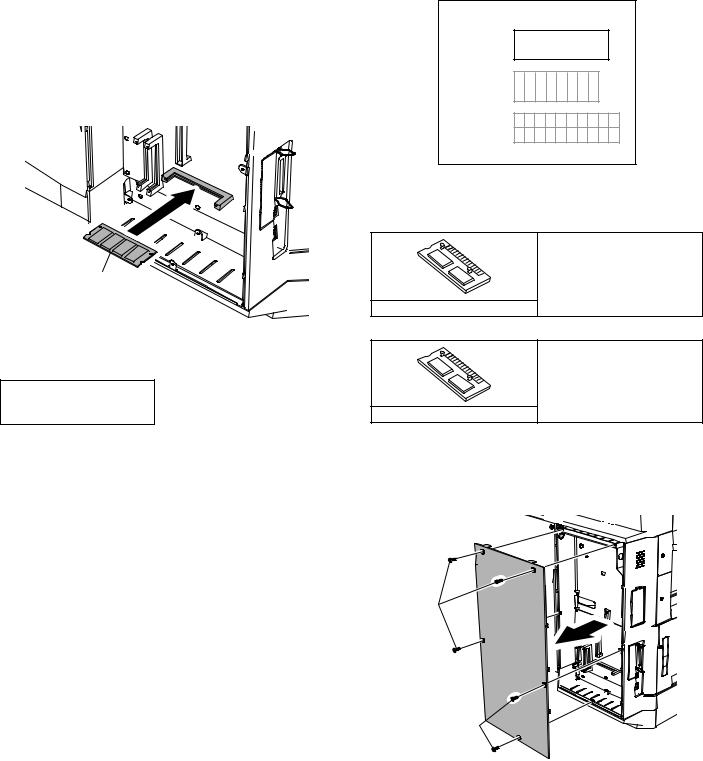
Insert the power plug of the copier to the outlet and turn on the main switch. Then, carry out the following procedure.
5)Check for the PCL PWB.
Press the PRINT key on the operation panel to check to see if the copier enters the print mode.
6)Check for the language.
Check for the language setting (26-22) following the procedure described in the service manual (section of simulation).
7)Check for printing.
For installation of printer drivers on a computer, see the supplied operation manual.
Then, connect a parallel cable to the computer and execute printing to check to see if printing can be executed properly.
(3) Mounting of additional memory
(After mounting it, Installation proceed to step 4.)
Insert the memory module until it clicks.
The memory module is lock when it is inserted. However, be sure to check that the module slit is engaged with the connector rib when it is inserted.
Memory module (S.O.DIMM)
B. AR-PK1
(1) Parts included
CD-ROM: 1*
License agreement
Installation caution sheet
*NOTE: Do not use the CD-ROM packed in AR-PK1, but use the CDROM packed together with the AR-P17 for setting the PS driver.
(2) Installation procedure
To enable the PS3, the product key must be acquired.
(For the method of acquiring the product key, contact the SHARP authorized dealer.)
1)Check that AR-P17 operates normally.
•Turn on the power and wait until warming up is complete.
•Press the PRINT key on the operation panel of the main unit.
•If the LCD in the operation panel of the main unit switches to the print mode normally, AR-P17 is operating normally.
•If it is not operating normally, follow the AR-P17 Installation Manual to check and modify the system configuration settings and check the operation.
2)Enable the PS3.
To enable the system configuration, use the keys on the main unit to set the mode.
Enter the product key with the key operator program. (Refer to the Operation Manual of Key Operator Program.)
Setting of the product key is complete. To update the system, press the CA key to exit the setting mode.
3)Check the PS3.
Make the following sequence of selections on the control panel.
•Press Special Functions , highlight Configuration and press OK.
•Use the up and down keys to highlight Test print menu and press OK.
•Use the up/down keys to highlight Configuration page and press OK.
A configuration page will be printed.
Check that the option memory capacity is 128 MB or more.
Check that the PS3 has been installed.
Please keep below important information.
This information will use for other products.
APPLICATION
NUMBER
MACHINE
SERIAL
NUMBER
PRODUCT
KEY
C. AR-PF1/PF2
(1) Parts included
AR-PF1
CD-ROM: 1 pc.
Operation manual
Installation caution sheet
Bar code board: 1 pc.
AR-PF2
Operation manual
Installation caution sheet
Flash ROM board: 1 pc.
(2) Installation
Turn off the main switch of the copier and then remove the power plug of the copier from the outlet.
1)Remove the shielding plate.
Remove five screws and remove the shielding plate.
Screws
Screws 
AR-M236/M276/M237/M277 UNPACKING AND INSTALLATION 5 - 6
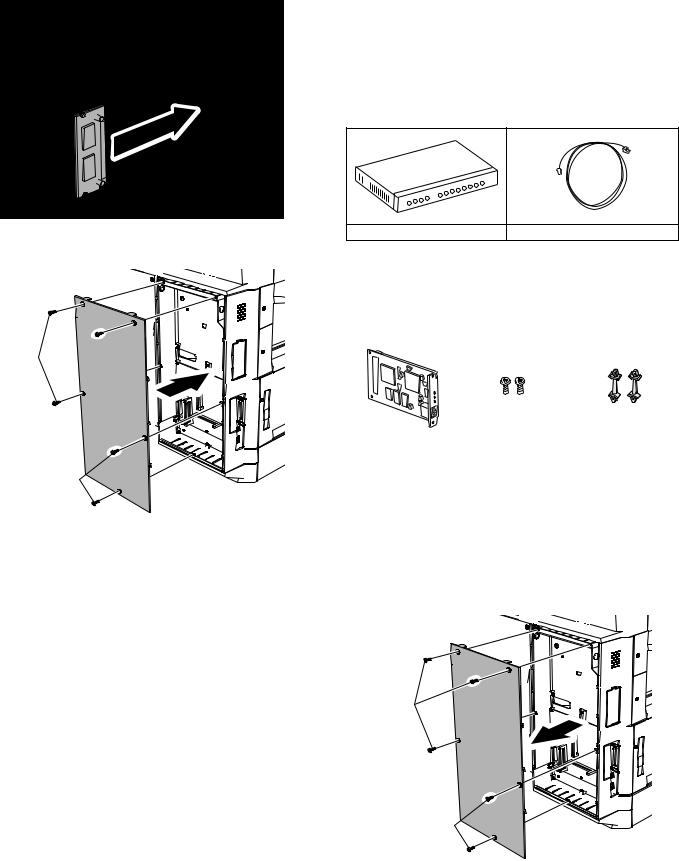
2)Attach the bar code board/flash ROM.
Attach the bar code board/flash ROM board to CN7 of the printer board.
Bar code board/
Flash ROM board/
Font ROM board
3)Attach the shielding plate.
Attach the shielding plate using the five screws.
Screws 
Screws 
Insert the power plug of the copier to the outlet and turn on the main switch. Then, carry out the following procedure.
4)Check the bar codes. (AR-PF1 only)
Use the operation keys on the operation panel to print the PCL font list from the test page printing.
Check that the optional font list is printed at the end.
(3) |
Font list |
|
|
||
Font |
Font name |
Font |
Font name |
||
No. |
No. |
||||
|
|
||||
1 |
|
Code128TT-Regular |
15 |
OCR-A |
|
2 |
|
Code128-NarrowTT-Regular |
16 |
OCR-B |
|
3 |
|
Code128-WideTT-Regular |
17 |
OCR-B-C39-Regular |
|
4 |
|
Code39HalfInch-Regular |
18 |
Upc-Half |
|
5 |
|
Code39OneInch-Regular |
19 |
Upc-Half-Bars |
|
6 |
|
Code39QuarterInch-Regular |
20 |
Upc-HalfMusic |
|
7 |
|
Code39SmallHigh-Regular |
21 |
Upc-HalfNarrow |
|
8 |
|
Code39Slim-Regular |
22 |
Upc-HalfThin |
|
9 |
|
Code39SmallLow-Regular |
23 |
Upc-Tall-Regular |
|
10 |
|
Code39SmallMedium-Regular |
24 |
Upc-TallBarsThin-regular |
|
11 |
|
Code39Wide-Regular |
25 |
Upc-TallMusicThin-Regular |
|
12 |
|
Codabar-Regular |
26 |
Upc-TallNarrow-Regular |
|
13 |
|
Interleaved2of5-Regular |
27 |
Upc-TallThin-regular |
|
14 |
|
Interleaved2of5-Thin-Regular |
28 |
ZipCodeBarcode-Regular |
|
(4) Check when installing the AR-PF2
Check can be made by print out of the printer setting list.
The expansion font item in the printer setting list is changed from "uninstalled" to "download font."
D. AR-NC5J
(1) Connection to a network
To connect the AR-NC5J to a network, the following items are required.
•For connection in the 100BASE-TX environment, a hub conforming to 100BASE-TX and a shield-type, twisted-pair cable (Category 5) are required.
1 2 3 4 5 6 7 8
Hub |
Shield-type, twisted-pair cable |
1)Check that the printer power is off, and connect the shield-type, twisted-pair cable to the 10/100BASE connector of the AR-NC5J.
2)Connect the other end of the cable to the hub.
3)Turn on the printer power, and check that the printer operates normally.
(2) Parts included
|
|
|
|
Print server card: |
Screws (silver) |
Spacers: |
|
2 pcs. (only the one is |
|||
1 pc. |
M3 x 8: 2 pcs. |
||
used) |
|||
|
|
||
|
|
|
|
CD-ROM: 1 pc. |
Operation manual |
Installation caution |
|
sheet |
|||
|
|
(3) Installation procedure
In this case, no spacer is used in the packed items of the AR-NC5J.
Turn off the main switch of the copier and then remove the power plug of the copier from the outlet.
1)Remove the shielding plate.
Remove five screws and remove the shielding plate.
Screws
Screws 
AR-M236/M276/M237/M277 UNPACKING AND INSTALLATION 5 - 7

2)Cut and remove the cut-out portion from the left rear cabinet.
Cut and remove the cut-out portion from the left rear cabinet using a tool such as nippers. (Be careful about the direction of the tool so that the cut surface is flat.)
5)Connect the cable to the control PWB.
Connect a LAN cable to the connector of the print server card.
LAN cable
Cut-out portion
3)Attach the print server card.
Align the connector positions, connect the print server card, and then secure the card to the option mounting plate in the main unit using supplied two silver screws (M3 x 8).
Silver screws (M3 x 8)
Print server card
4)Reattach the shielding plate.
Reattach the shielding plate using five screws.
Screws
Screws
Insert the power plug of the copier to the outlet and turn on the main switch. Then, carry out the following procedure.
6)Check for the print server card.
Use the keys on the operation panel to print a configuration page. Check that the network interface card has been installed.
7)Check for printing.
Perform setup of the environmental variables.
(For installation of printer drivers on a computer and network settings (IP address input), see the supplied operation manual.) Execute printing to check to see if printing can be executed properly.
E. AR-NS2
(1) Packed items
This network scanner kit includes the following items in the package.
•CD-ROM (Network Scanner Tool and Sharpdesk, Installer, Sharp TWAIN driver, etc.)
•Installation caution sheet and Operation Manual (License numbers of 10 user clients of Sharpdesk are specified.)
(2) Installation procedure
To use the scanner expansion kit, a S.O.DIMM memory module (128 MB or more) is needed.
If no memory is added, an S.O.DIMM module must be mounted on PCL PWB.
For the mounting method and the memory capacity, see below.
To enable the scanner function, the product key must be acquired. (For the method of acquiring the product key, contact the SHARP authorized dealer.)
1)Check the capacity of the Printer PWB memory.
Use the keys of the copier to print the configuration page. (For details, see the operation manual.)
Check that the capacity of the optional memory is 128 MB or more.
2)Enable the network scanner feature.
To enable the system configuration, use the keys on the copier to set the mode.
Enter the product key with the key operator program. (Refer to the Operation Manual of Key Operator Program.)
Setting of the product key is completed. Press the [EXIT] key to update the system and exit the setting mode.
AR-M236/M276/M237/M277 UNPACKING AND INSTALLATION 5 - 8
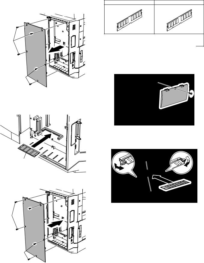
(3) Mounting the additional memory |
F. AR-SM5/SM6 |
|
|
Turn off the main switch of the copier and then remove the power |
(1) Parts included |
|
|
plug of the copier from the outlet. |
|
||
AR-SM5 |
AR-SM6 |
||
1) Remove the shielding plate. |
|||
|
|
||
Remove the five screws and remove the shielding plate. |
|
|
Screws
Screws 
2)Mount the memory module.
Insert the memory module until it clicks.
The memory module is lock when it is inserted. However, be sure to check that the module slit is engaged with the connector rib when it is inserted.
Memory module (S.O.DIMM)
3)Reattach the shielding plate.
Reattach the shielding plate using the five screws.
Screws 
Screws 
256MB SDRAM memory module |
512MB SDRAM memory module |
(168 pin DIMM): 1 pc. |
(168 pin DIMM): 1 pc. |
Installation caution sheet |
Installation caution sheet |
(2) Installation procedure
Turn off the main switch of the copier and then remove the power plug of the copier from the outlet.
1)Remove the shielding plate.
Remove the screw and remove the cabinet.
2)Attach the SDRAM memory module.
Attach the SDRAM memory module to CN1 and CN2 of the IMC board.
When only one SDRAM memory module is used, attach it to CN1.
CN2
CN1
AR-M236/M276/M237/M277 UNPACKING AND INSTALLATION 5 - 9
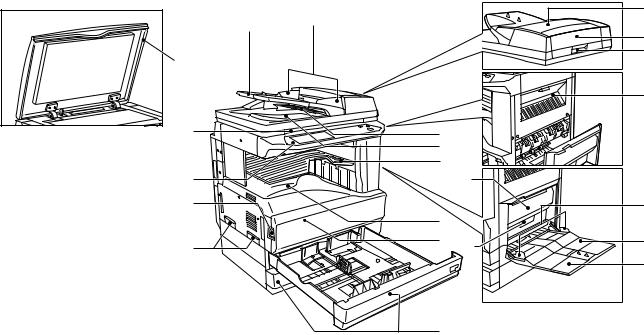
[6] EXTERNAL VIEW AND INTERNAL STRUCTURE
1. Name and function of each section
A. External view
|
|
4 |
|
2 |
3 |
|
7 |
|
|
|
|
1 |
|
8 |
|
|
|
|
|
17 |
9 |
|
5 |
|
|
6 |
|
|
13 |
12 |
|
19 |
10 |
|
20 |
|
14 |
|
11 |
15 18 |
21 |
|
|
22 |
|
|
16 |
|
|
|
|
|
No. |
Name |
Function/Operation |
Note |
1 |
Platen cover (optional) |
Presses a document. |
Optional (AR-M236/M276) |
2 |
Document feeder tray |
Place the original(s) that you wish to scan face up here. |
When the reversing single |
3 |
Original guides |
Adjust to the size of the originals. |
pass feeder installed. (AR- |
4 |
Document feeder cover |
Open to remove misfed originals. |
M237/M277: Standard) |
5 |
Reversing tray |
Pull out to remove misfed originals. |
|
6 |
Exit area |
Originals exit the machine here after copying. |
|
7 |
Document transport cover |
Open to remove misfed originals. |
|
8 |
Document transport cover knob |
Pull to open the document transport cover. |
|
9 |
Document glass |
Place an original that you wish to scan face down here. |
|
10 |
Power switch |
Press to turn the machine power on and off. |
|
11 |
Handles |
Use to move the machine. |
|
12 |
Operation panel |
Contains operation keys and the touch panel. |
|
13 |
Job separator tray (optional) |
Print jobs and received faxes are delivered to this tray. |
When the job separator |
|
|
|
tray installed. |
14 |
Center tray |
Finished copies are delivered to the center tray. |
|
15 |
Front cover |
Open to remove paper misfeeds and perform machine maintenance. |
|
16 |
Paper trays |
Each tray holds 500 sheets of copy paper. |
|
17 |
Upper right side cover |
Open to remove misfeeds when an optional job separator tray kit or a |
|
|
|
optional finisher is installed. |
|
18 |
Side cover |
Open to remove misfeeds. |
|
19 |
Side cover handle |
Pull to open the side cover. |
|
20 |
Bypass tray paper guides |
Adjust to the width of the paper. |
|
21 |
Bypass tray |
Regular paper and special paper (such as transparency film) can be fed |
|
|
|
from the bypass tray. |
|
22 |
Bypass tray extension |
Pull out the bypass tray extension before placing paper in the bypass tray. |
|
AR-M236/M276/M237/M277 EXTERNAL VIEW AND INTERNAL STRUCTURE 6 - 1
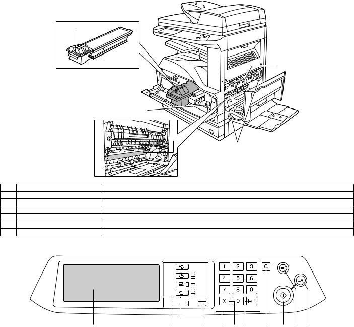
B. Internal structure
1
2 |
6 |
|
3
4
5
No. |
Name |
Function/Operation |
1 |
Toner cartridge lock release lever |
Use to unlock the toner cartridge. |
2 |
Toner cartridge |
Contains toner. |
3 |
Roller rotating knob |
Turn to remove misfed paper. |
4 |
Photoconductive drum |
Copy images are formed on the photoconductive drum. |
5 |
Fusing unit release levers |
To remove a paper misfeed in the fusing unit, push up on these levers and remove the paper. |
6 |
Fusing unit paper guide |
Open to remove misfed paper. |
C. Operation panel
COPY |
|
|
ON LINE |
||
DATA |
||
|
||
SCAN |
DATA |
|
FAX |
LINE |
|
DATA |
||
|
||
JOB STATUS |
CUSTOM SETTINGS |
|
|
ACC.#-C |
|
1 |
2 |
3 |
4 |
5 |
6 |
7 |
8 |
9 |
10 |
11 |
|
|
|
|
|
|
|
|
|
|
|
|
|
|
No. |
Name |
|
Function/Operation |
|
|
|
|
|
|
|
Note |
|
1 |
Touch panel |
The machine status, messages and touch keys are displayed on the panel. The |
|
|
|
|||||||
|
|
display will show the status of printing, copying or network scanning according |
|
|
|
|||||||
|
|
to the mode that is selected. |
|
|
|
|
|
|
|
|
|
|
2 |
Mode select keys and indicators |
Use to change modes and the corresponding display on the touch panel. |
|
|
|
|
||||||
|
[COPY] key |
Press to select copy mode. |
|
|
|
|
|
|
|
|
|
|
|
[PRINT] key/ONLINE indicator/ |
[PRINT] key: Press to select print mode. |
|
|
|
|
|
|
|
|
|
|
|
DATA indicator |
• ONLINE indicator: Print jobs can be received when this indicator is lit. |
|
|
|
|
||||||
|
|
• DATA indicator: A print job is in memory. The indicator lights steadily while |
|
|
|
|||||||
|
|
the job is held in memory, and blinks while the job is printed. |
|
|
|
|
|
|||||
|
[SCAN] key/DATA indicator |
[SCAN] key: Press to select network scan mode when the network scanner |
|
|
When the network |
|||||||
|
|
option is installed. |
|
|
|
|
|
|
|
|
scanner option is |
|
|
|
• DATA indicator: Lights steadily or blinks while a scanned image is being sent. |
installed. |
|||||||||
|
[FAX] key/LINE indicator/ |
[FAX] key: Press to select fax mode when the fax function is installed. |
|
|
When the fax function |
|||||||
|
DATA indicator |
• LINE indicator: This lights up while faxes are being sent or received. |
|
|
is installed. |
|||||||
|
|
• DATA indicator: Blinks when a fax has been received to memory and lights |
|
|
|
|||||||
|
|
steadily when a fax is waiting in memory for transmission. |
|
|
|
|
|
|||||
3 |
[JOB STATUS] key |
Press to display the current job status. |
|
|
|
|
|
|
|
|
|
|
AR-M236/M276/M237/M277 EXTERNAL VIEW AND INTERNAL STRUCTURE 6 - 2
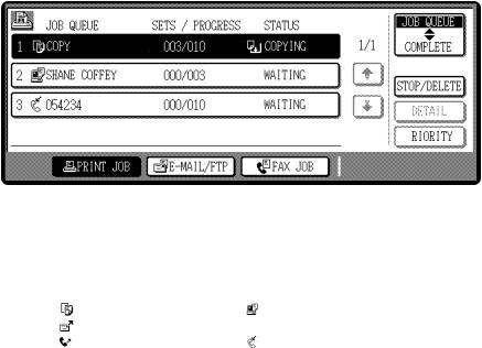
No. |
Name |
Function/Operation |
Note |
4 |
[CUSTOM SETTINGS] key |
Use to adjust various settings of the machine including the contrast of the touch |
|
|
|
panel and key operator programs. |
|
5 |
Numeric keys |
Use to enter numeric values for various settings. |
|
6 |
[ACC.#-C] key |
When auditing mode is enabled, press this key after finishing a job to return the |
|
|
|
machine to account number entry standby. |
|
7 |
[#/P] key |
Use this key to execute a job program in copy mode. The key is also used to |
|
|
|
dial in fax mode. |
|
8 |
[CLEAR] key |
Press to clear a copy number setting or cancel a job. |
|
9 |
[START] key |
Press in copy mode, scanner mode, or fax mode to begin copying, network |
|
|
|
scanning, or faxing. |
|
10 |
[INTERRUPT] key |
Use to perform an interrupt copy job. |
|
11 |
[CLEAR ALL] key |
Resets the settings to the initial settings. |
|
D. Job status screen
This screen appears when the [JOB STATUS] key on the operation panel is pressed.
A job list showing the current job and the stored jobs or a list showing completed jobs can be displayed.
The contents of jobs can be viewed and jobs can be deleted from the queue. The following screen shows the job queue for print jobs.
1 |
|
|
|
|
|
|
|
|
|
|
|
|
|
|
|
|
|
|
|
|
|
|
|
|
|
|
2 |
||||||
|
|
|
|
|
|
|
|
|
|
|
|
|
|
|
|
|
|
|
|
|
|
|
|
|
|
|
|
|
|
|
|
|
|
|
|
|
|
|
|
|
|
|
|
|
|
|
|
|
|
|
|
|
|
|
|
|
|
|
|
|
|
JOB QUEUE |
|
|
|
||
|
|
JOB QUEUE |
|
|
SETS / PROGRESS |
|
STATUS |
|
|
|
|
|
|
|
|
|
|
||||||||||||||||
|
|
|
|
|
|
|
|
|
|
|
|
|
|
|
|
|
|
|
|
|
|||||||||||||
|
|
|
COPY |
|
|
|
003 |
/ 000 |
|
|
PAPER EMPTY*1 |
|
|
1/1 |
|
|
|
COMPLETE |
|
|
|
||||||||||||
|
|
|
|
|
|
|
|
|
|
|
|
|
|
|
|
|
|
|
|
|
|
|
|
|
|
|
|
|
|
|
|
|
|
|
|
|
SHARP001 |
|
|
003 |
/ 000 |
|
|
WAITING |
|
|
|
|
|
|
|
|
|
|
|
|
|
|
|||||||||
|
|
|
|
|
|
|
|
|
|
|
|
|
|
|
|
|
|
|
|
|
|
|
|
|
|
|
|
DETAIL |
|
|
|
||
|
|
|
|
|
|
|
|
|
|
|
|
|
|
|
|
|
|
|
|
|
|
|
|
|
|
|
|
|
|
|
|||
|
|
|
|
|
|
|
|
|
|
|
|
|
|
|
|
|
|
|
|
|
|
|
|
|
|
|
|
|
|
|
|||
|
|
|
|
|
|
|
|
|
|
|
|
|
|
|
|
|
|
|
|
|
|
|
|
|
|
|
|
|
|
|
|
|
|
|
|
0666211221 |
|
|
010 |
/ 000 |
|
|
WAITING |
|
|
|
|
|
|
|
|
|
|
|
|
|
|
||||||||||
|
|
|
|
|
|
|
|
|
|
|
|
PRIORITY |
|
|
|
||||||||||||||||||
|
|
|
|
|
|
|
|
|
|
|
|
|
|
|
|
|
|
|
|
|
|
|
|
|
|
|
|
|
|
|
|||
|
|
|
|
|
|
|
|
|
|
|
|
|
|
|
|
|
|
|
|
|
|
|
|
|
|
|
|
|
|
|
|
|
|
|
|
|
|
|
|
|
|
|
|
|
|
|
|
|
|
|
|
|
|
|
|
|
|
|
|
|
|
|
|
|
|
|
|
|
|
|
|
|
|
|
|
|
|
|
|
|
|
|
|
|
|
|
|
|
|
|
|
|
|
|
|
STOP/DELETE |
|
|
|
||
|
|
|
|
|
|
|
|
|
|
|
|
|
|
|
|
|
|
|
|
|
|
|
|
|
|
|
|
|
|
|
|
|
|
|
|
|
|
|
|
|
|
|
|
|
|
|
|
|
|
|
|
|
|
|
|
|
|
|
|
|
|
|
|
|
|
|
|
|
|
|
|
PRINT JOB |
|
|
|
|
E-MAIL/FTP |
|
|
|
FAX JOB |
|
|
|
|
|
|
|
|
|
|
|
|
|
|
|
|||||
|
|
|
|
|
|
|
|
|
|
|
|
|
|
|
|
|
|
|
|
|
|
|
|
|
|
|
|
|
|
|
|
|
|
|
|
3 |
4 |
5 |
6 |
7 |
8 |
9 |
|
|
|
|
|
|
|
|
|
No. |
Name |
|
Function/Operation |
|
|
|
Note |
|
1 |
Job list |
Shows stored jobs and the job currently being executed. Touch one |
* 1 :"PAPER EMPTY" in the job status |
|||||
|
|
of keys 3 to 5 in the above illustration to select the type of job. The |
display |
|
|
|||
|
|
icon next to each job name indicates the mode of the job as follows: |
"PAPER EMPTY" in the job status display |
|||||
|
|
Copy mode |
|
Printer mode |
|
indicates that the machine is out of the |
||
|
|
Network scanner mode |
|
|
specified size of paper. Add the specified |
|||
|
|
Fax mode (Send jobs) |
Fax mode (Receive jobs) |
size of paper. If the specified size of paper |
||||
|
|
is not available and you are in printer mode, |
||||||
|
|
The jobs in the job list appear in the form of keys. To give priority to a |
||||||
|
|
another size of paper can be loaded in the |
||||||
|
|
job or pause or delete a job, touch the key of the job and then use the |
||||||
|
|
bypass tray to allow printing to take place. |
||||||
|
|
key described in 7 or 8. |
|
|
|
|||
|
|
|
|
|
|
|
|
|
2 |
Mode switching keys |
Use to select the job list mode: "JOB QUEUE" (Stored/currently |
|
|
|
|||
|
|
executing jobs) or "COMPLETE" (Finished jobs). |
|
|
|
|
||
|
|
"JOB QUEUE": Shows jobs that have been stored and the job that is |
|
|
|
|||
|
|
currently being executed. |
|
|
|
|
|
|
|
|
"COMPLETE": Shows the jobs that have been finished. Note that |
|
|
|
|||
|
|
copy jobs do not appear in this list (print job only). |
|
|
|
|
||
3 |
[PRINT JOB] key |
Use to view the list of output jobs for all modes (print, copy, and fax). |
|
|
|
|||
4 |
[E-MAIL/FTP] key |
Displays a network scanner job. |
|
|
When the network scanner function is |
|||
|
|
|
|
|
|
installed. |
|
|
5 |
[FAX JOB] key |
This displays stored fax jobs and the fax job currently being executed. |
When the fax function is installed. |
|||||
6 |
Display switching keys |
Use to change the page of the displayed job list. |
|
|
|
|
||
7 |
[STOP/DELETE] key |
Use to pause or delete a job currently being executed, or to delete a |
|
|
|
|||
|
|
stored job. Copy jobs and received faxes cannot be paused or |
|
|
|
|||
|
|
deleted with this key. Copy jobs can be canceled by pressing the |
|
|
|
|||
|
|
[CLEAR] key or [CLEAR ALL] key. |
|
|
|
|
|
|
8 |
[PRIORITY] key |
Select a reserved job in the [Reserve/Execution] job list and touch |
|
|
|
|||
|
|
this key, and the selected job will be executed by interrupting the |
|
|
|
|||
|
|
current execution of the other job. |
|
|
|
|
|
|
9 |
[DETAIL] key |
Shows information on the selected job. This cannot be used for a |
|
|
|
|||
|
|
received fax and copy. |
|
|
|
|
|
|
AR-M236/M276/M237/M277 EXTERNAL VIEW AND INTERNAL STRUCTURE 6 - 3

E. Motor, Solenoid, Clutch |
|
|
1 |
|
2 |
|
3 |
|
4 |
19 |
5 |
|
|
20 |
6 |
7 |
|
|
8 |
|
9 |
|
|
|
|
|
10 |
|
|
|
|
|
11 |
|
18 |
|
|
|
|
|
17 |
16 |
|
|
|
|
|
14 |
13 |
12 |
|
|
|
15 |
|||
No. |
Name |
Code |
Function and operation |
||
1 |
Mirror motor |
MIRM |
Optical mirror base |
||
|
|
|
drive |
|
|
2 |
Shifter motor |
SFTM |
Shifter drive |
||
3 |
Paper exit gate |
OGS |
Paper exit gate |
||
|
switching solenoid |
|
switcher |
|
|
4 |
Duplex motor |
DPXM |
Duplex paper switching |
||
|
|
|
and exit motor |
||
5 |
DUP-2 motor |
|
Reverse pass for paper |
||
|
|
|
transport |
|
|
6 |
Cooling fan |
VFM |
Cools the inside of the |
||
|
|
|
unit. |
|
|
7 |
Main motor |
MM |
Main drive |
|
|
8 |
PS clutch |
RRC |
Main unit paper feed |
||
9 |
Paper feed clutch |
CPFS1 |
Paper feed roller drive |
||
10 |
Manual paper feed |
MPFS |
Manual paper feed |
||
|
solenoid |
|
solenoid |
|
|
11 |
Paper feed transfer |
TRC2 |
Paper feed transfer |
||
|
clutch |
|
clutch |
|
|
12 |
2nd cassette paper |
CPFS2 |
|
|
|
|
feed clutch |
|
|
|
|
13 |
Cassette lift-up motor |
LUM1 |
Cassette paper lift-up |
||
14 |
Cassette lift-up motor |
LUM2 |
Cassette paper lift-up |
||
15 |
2nd cassette paper |
CPFC2 |
Solenoid for the paper |
||
|
feed solenoid |
|
feed from the cassette |
||
16 |
Paper feed solenoid |
CPFC1 |
Solenoid for the paper |
||
|
|
|
feed from the cassette |
||
17 |
Toner motor |
TM |
Toner supply |
||
18 |
Separation pawl |
PSPS |
Separation pawl |
||
|
solenoid |
|
operation solenoid |
||
19 |
Exhaust fan motor |
DCFM |
Cools the inside of the |
||
|
|
|
unit. |
|
|
20 |
Intake fan motor |
DCFM2 |
|
|
|
F. Sensor
1
2
3
30 |
4 |
5
6
7
8
9
29
10 |
11 |
12 |
28 |
|
|
13 |
27 |
26 |
|
14 |
|
25 |
15 |
|
|
|
||
|
|
24 |
|
|
|
|
|
23 |
|
|
|
|
|
|
22 |
21 |
|
|
|
|
|
|
19 |
31 |
18 |
17 16 |
|
|
|
20 |
||||
|
|
|
|
|
|
|
No. |
Name |
Code |
|
|
Function and |
|
|
|
operation |
||||
|
|
|
|
|
||
1 |
Mirror home position |
MHPS |
|
Mirror (scanner) home |
||
|
sensor |
|
|
position detection |
||
2 |
Document cover |
OCSW |
|
Document cover |
||
|
sensor |
|
|
open/close detection |
||
3 |
Document size sensor |
DSIN3 |
|
Document size |
||
|
|
|
|
detection (Inch series: |
||
|
|
|
|
PD3, 4) (AB series: |
||
|
|
|
|
PD4, 5) |
|
|
4 |
2nd paper exit sensor |
POD2 |
|
2nd paper exit |
||
|
|
|
|
detection |
|
|
5 |
2nd paper exit full |
TOPF |
|
2nd paper exit section |
||
|
detection sensor |
|
|
full detection |
||
6 |
Right cabinet door |
DSWR0 |
|
Right cabinet door |
||
|
switch |
|
|
open/close detection |
||
7 |
1st paper exit sensor |
POD1 |
|
1st paper exit |
||
|
|
|
|
detection |
|
|
8 |
Shifter home position |
SFTHP |
|
Shifter home position |
||
|
sensor |
|
|
sensor detection |
||
9 |
Paper exit sensor |
PPD2 |
|
Paper exit detection |
||
|
(DUP side) |
|
|
|
|
|
10 |
Thermistor |
|
|
Fusing temperature |
||
|
|
|
|
detection |
|
|
11 |
Thermostat |
|
|
Abnormal high |
||
|
|
|
|
temperature detection |
||
|
|
|
|
in the fusing section |
||
12 |
1st cassette (paper |
CD1 |
|
1st cassette (paper |
||
|
tray) detection |
|
|
tray) empty detection |
||
13 |
Manual feed paper |
PPD1L |
|
Sensor of paper entry |
||
|
entry sensor |
|
|
from the manual |
||
|
|
|
|
paper feed tray, the |
||
|
|
|
|
2nd/multi-stage desk, |
||
|
|
|
|
or the DUP |
||
14 |
Manual paper feed |
MPLS2 |
|
Manual feed tray |
||
|
tray empty sensor 2 |
|
|
position detection |
||
15 |
Manual paper feed |
MPLS1 |
|
Manual feed tray |
||
|
tray empty sensor 1 |
|
|
position detection |
||
16 |
Manual feed length |
MPLD1 |
|
Manual feed paper |
||
|
detection sensor 1 |
|
|
length detection |
||
17 |
Manual feed length |
MPLD2 |
|
Manual feed paper |
||
|
detection sensor 2 |
|
|
length detection |
||
AR-M236/M276/M237/M277 EXTERNAL VIEW AND INTERNAL STRUCTURE 6 - 4
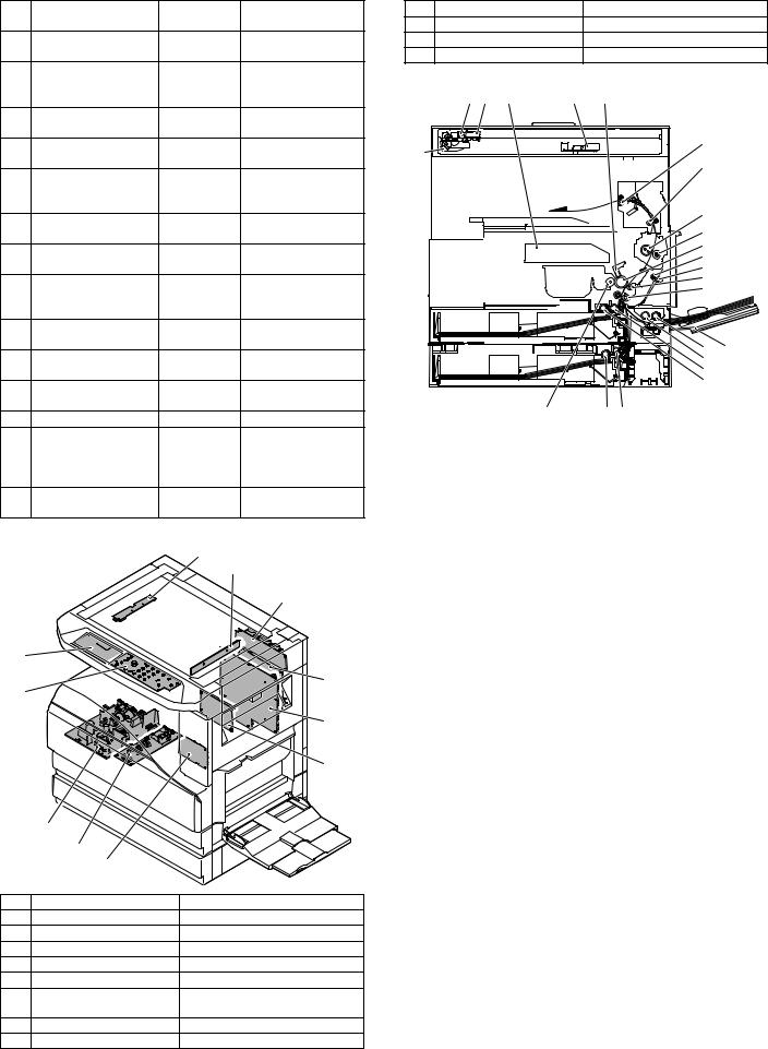
No. |
Name |
Code |
Function and |
|
operation |
||||
|
|
|
||
18 |
Manual feed paper |
MPED |
Manual feed paper |
|
|
empty sensor |
|
empty detection |
|
19 |
Door switch |
DSWR1 |
Front door and side |
|
|
|
|
door open/close |
|
|
|
|
detection |
|
20 |
2nd right door switch |
DSWR2 |
Side door open/close |
|
|
|
|
detection |
|
21 |
2nd cassette paper |
PFD2 |
2nd cassette paper |
|
|
pass sensor |
|
pass |
|
22 |
2nd cassette paper |
LUD2 |
2nd cassette paper |
|
|
upper limit detection |
|
upper limit detection |
|
|
sensor |
|
|
|
23 |
2nd cassette paper |
PED2 |
2nd cassette paper |
|
|
empty sensor |
|
empty detection |
|
24 |
1st cassette paper |
PPD1H |
1st cassette paper |
|
|
pass sensor |
|
pass |
|
25 |
1st cassette paper |
LUD1 |
1st cassette paper |
|
|
upper limit detection |
|
upper limit detection |
|
|
sensor |
|
|
|
26 |
1st cassette paper |
PED1 |
1st cassette paper |
|
|
empty sensor |
|
empty detection |
|
27 |
Toner sensor |
|
Toner density |
|
|
|
|
detection |
|
28 |
Center tray paper |
LOEMP |
Center tray paper |
|
|
YES/NO sensor |
|
YES/NO detection |
|
29 |
Main switch |
PSSW |
Main power switch |
|
30 |
Original size sensor |
DSIN0 |
Document size |
|
|
|
|
detection (Inch series: |
|
|
|
|
PD1, 2) (AB series: |
|
|
|
|
PD1 – 3) |
|
31 |
Reverse pass paper |
DUP2 |
Reverse pass |
|
|
detection sensor |
|
detection |
|
G. PWB unit |
|
|
||
|
|
1 |
|
|
|
|
2 |
|
|
|
|
|
3 |
|
11 |
|
|
|
|
10 |
|
|
4 |
|
|
|
|
||
|
|
|
5 |
|
|
|
|
6 |
|
|
9 |
|
|
|
|
8 |
|
|
|
|
7 |
|
|
|
No. |
Name |
Function and operation |
||
1 |
Inverter PWB |
Copy lamp control |
||
2 |
CCD PWB |
For image scanning (read) |
||
3 |
Option connector PWB |
|
|
|
4 |
IMC PWB |
Image process |
||
5 |
MCU PWB |
Main unit control |
||
6 |
Mother board |
Connection with FAX PWB and |
||
|
|
PCL PWB |
|
|
7 |
Tray interface PWB |
2nd tray control |
||
8 DC power supply PWB |
DC voltage control |
|||
No. |
|
|
Name |
|
Function and operation |
9 |
High voltage PWB |
|
High voltage control |
||
10 |
KEY PWB |
|
|
|
|
11 |
OPU PWB |
|
Operation panel control |
||
H. Section |
|
|
|
|
|
|
1 |
2 |
3 |
4 |
5 |
|
|
|
|
|
6 |
23 |
|
|
|
|
|
|
|
|
|
|
7 |
8 |
9 |
10 |
11 |
12 |
13 |
14 |
16 15
17
18
19
|
22 |
21 |
20 |
|
|
|
|
No. |
Name |
|
Function and operation |
1 |
Copy lamp |
Image radiation lamp |
|
2 |
Copy lamp unit |
Operates in synchronization with |
|
|
|
2nd/3rd mirror unit to radiate |
|
|
|
documents sequentially. |
|
3 |
LSU unit |
Converts image signals into laser |
|
|
|
beams to write on the dum. |
|
4 |
Lens unit |
Reads images with the lens and |
|
|
|
the CCD. |
|
5 |
MC holder unit |
Supplies negative charges evenly |
|
|
|
on the drum. |
|
6 |
Paper exit roller |
Paper exit roller |
|
7 |
Transport roller |
Paper transport roller |
|
8 |
Upper heat roller |
Fuses toner on paper. |
|
|
|
(with the Teflon roller) |
|
9 |
Lower heat roller |
Fuses toner on paper. |
|
|
|
(with the silicone rubber roller) |
|
10 |
Drum unit |
Forms images. |
|
11 |
DUP transport follower |
Duplex paper transport |
|
|
roller |
|
|
12 |
DUP transport roller |
Duplex paper transport |
|
13 |
Transport roller |
Transfer images on the drum onto |
|
|
|
paper. |
|
14 |
Resist roller |
Synchronize the paper lead edge |
|
|
|
with the image lead edge. |
|
15 |
Manual feed tray |
Manual feed paper tray |
|
16 |
Manual paper feed roller |
Picks up papers in manual paper |
|
|
|
feed port. |
|
17 |
Manual feed transport |
Transports paper from the manual |
|
|
roller |
paper feed port. |
|
18 |
1st cassette pick-up |
Picks up paper from the cassette. |
|
|
roller |
|
|
19 |
1st cassette paper feed |
Transports the picked up paper to |
|
|
roller |
RESIST section. |
|
20 |
2nd cassette pick-up |
Picks up paper from the cassette. |
|
|
roller |
|
|
21 |
2nd cassette paper feed |
Transports the picked up paper to |
|
|
roller |
RESIST section. |
|
22 |
MG roller |
Puts toner on the OPC drum. |
|
23 |
2nd/3rd mirror unit |
Reflects the images from the copy |
|
|
|
lamp unit to the lens unit. |
|
AR-M236/M276/M237/M277 EXTERNAL VIEW AND INTERNAL STRUCTURE 6 - 5
Loading...