


LC 52LE920UN
LC-52LE920UN/LC-60LE920UN
SHARP SERVICE MANUAL
No. S701560LE920U/
LCD COLOR TELEVISION
LC-52LE920UN
MODELS
In the interests of user-safety (Required by safety regulations in some countries) the set should be restored to its orig-
inal condition and only parts identical to those specified should be used.
LC-60LE920UN
F CONTENTS
SAFETY PRECAUTION
IMPORTANT SERVICE SAFETY
PRECAUTION .................................................... i
PRECAUTIONS A PRENDRE LORS DE
LA REPARATION .............................................. ii
PRECAUTIONS FOR USING LEAD-FREE
SOLDER .......................................................... iii
OUTLINE
MAJOR SERVICE PARTS ............................... iv
CHAPTER 1. SPECIFICATIONS
[1] SPECIFICATIONS ........................................ 1-1
[2] REMOVING OF MAJOR PARTS
(LC-60LE920UN) ........................................... 4-6
[3] Caution Cleaning Glass ............................... 4-11
[4] How to replace the touch keysensor PWB...... 4-13
CHAPTER 5. ADJUSTMENT
[1] ADJUSTMENT PROCEDURE ...................... 5-1
[2] PUBLIC MODE SETTING PROCEDURE ...... 5-15
CHAPTER 6. TROUBLESHOOTING TABLE
[1] TROUBLESHOOTING TABLE ...................... 6-1
[2] LED flashing specification at the time of an
error (Center icon LED used) ...................... 6-14
CHAPTER 2. OPERATION MANUAL
[1] Parts Name ................................................... 2-1
[2] OPERATION MANUAL ................................. 2-3
CHAPTER 3. DIMENSIONS
[1] DIMENSIONS (LC-52LE920UN) ................... 3-1
[2] DIMENSIONS (LC-60LE920UN) ................... 3-2
CHAPTER 4. REMOVING OF MAJOR PARTS
[1] REMOVING OF MAJOR PARTS
(LC-52LE920UN) .......................................... 4-1
CHAPTER 7. MAJOR IC INFORMATIONS
[1] MAJOR IC INFORMATIONS ......................... 7-1
CHAPTER 8. OVERALL WIRING/SYSTEM BLOCK
DIAGRAM
[1] OVERALL WIRING DIAGRAM ...................... 8-1
[2] SYSTEM BLOCK DIAGRAM ......................... 8-2
Parts Guide
J
Parts marked with "Z_._ " are important for maintaining the safety of the set. Be sure to replace these parts with specified ones for maintaining the
safety and performance of the set.
This document has been published to be used for
SHARP CORPORATION
after sales service only.
The contents are subject to change without notice.
LC-52LE920UN/LC-60LE920UN
SAFETY PRECAUTION
IMPORTANT SERVICE SAFETY PRECAUTION
[] Service work should be performed only by qualified service technicians who are thoroughly familiar with all safety checks and the
servicing guidelines which follow:
==WARNING
1. For continued safety, no modification of any circuit should be
attempted.
2. Disconnect AC power before servicing.
CAUTION: FOR CONTINUED PROTECTION
AGAINST A RISK OF FIRE REPLACE ONLY WITH
SAME TYPE FUSE,
F7000 (250V 5A)
F7001 (250V 5A)
==BEFORE RETURNING THE RECEIVER (Fire &
Shock Hazard)
Before returning the receiver to the user, perform the following
safety checks:
3. Inspect all lead dress to make certain that leads are not pinched,
and check that hardware is not lodged between the chassis and
other metal parts in the receiver.
4. Inspect all protective devices such as non-metallic control knobs,
insulation materials, cabinet backs, adjustment and compartment
covers or shields, isolation resistor-capacitor networks, mechanical
insulators, etc.
5. To be sure that no shock hazard exists, check for leakage current in
the following manner.
Plug the AC cord directly into a 120 volt AC outlet.
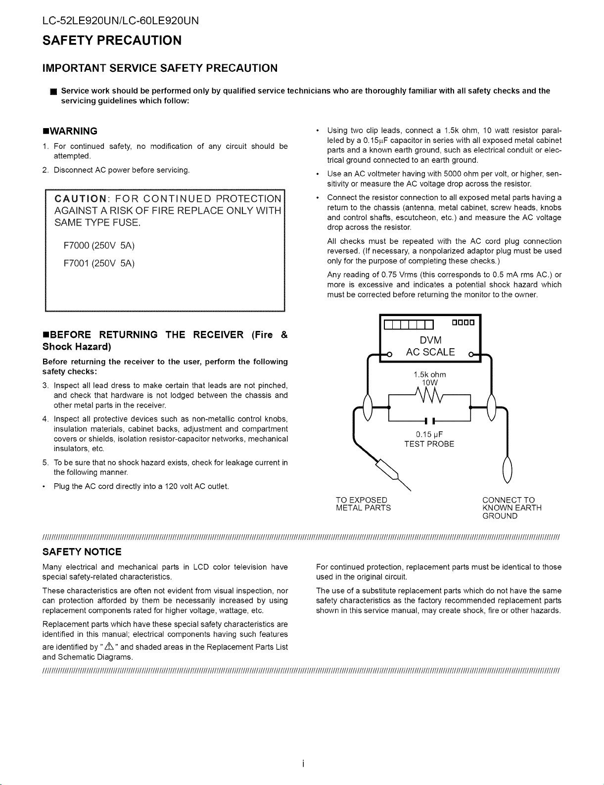
Using two clip leads, connect a 1.5k ohm, 10 watt resistor paral-
leled by a 0.15f_F capacitor in series with all exposed metal cabinet
parts and a known earth ground, such as electrical conduit or elec-
trical ground connected to an earth ground.
Use an AC voltmeter having with 5000 ohm per volt, or higher, sen-
sitivity or measure the AC voltage drop across the resistor.
Connect the resistor connection to all exposed metal parts having a
return to the chassis (antenna, metal cabinet, screw heads, knobs
and control shafts, escutcheon, etc.) and measure the AC voltage
drop across the resistor.
All checks must be repeated with the AC cord plug connection
reversed. (If necessary, a nonpolarized adaptor plug must be used
only for the purpose of completing these checks.)
Any reading of 0.75 Vrms (this corresponds to 0.5 mA rms AC.) or
more is excessive and indicates a potential shock hazard which
must be corrected before returning the monitor to the owner.
II-I-I-I-I-N oooo I
/ DVM /
rt.o ACSCALE o_-_
/ 1.5k ohm |
EOT15RbFBE
TO EXPOSED CONNECT TO
METAL PARTS KNOWN EARTH
GROUND
__________________________________________________________________________________________________________________________________________________________________________________________________________________________________________
SAFETY NOTICE
Many electrical and mechanical parts in LCD color television have
special safety-related characteristics.
These characteristics are often not evident from visual inspection, nor
can protection afforded by them be necessarily increased by using
replacement components rated for higher voltage, wattage, etc.
Replacement parts which have these special safety characteristics are
identified in this manual; electrical components having such features
are identified by "/i',," and shaded areas in the Replacement Parts List
and Schematic Diagrams.
__________________________________________________________________________________________________________________________________________________________________________________________________________________________________________
For continued protection, replacement parts must be identical to those
used in the original circuit.
The use of a substitute replacement parts which do not have the same
safety characteristics as the factory recommended replacement parts
shown in this service manual, may create shock, fire or other hazards.
LC-52LE920UN/LC-60LE920UN
PRECAUTIONS A PRENDRE LORS DE LA REPARATION
• Ne peut effectuer la r_paration qu' un technicien sp_cialis6 qui s'est parfaiternent accoutume a toute v_rification de s6curite et aux
conseils suivants.
• AVERTISSEMENT
1. N'entreprendre aucune modification de tout circuit. C'est danger-
eux.
2. Debrancher le r6cepteur avant toute r6paration.
PRECAUTION: POUR LA PROTECTION CON-
TINUE CONTRE LES RISQUES D'INCENDIE,
REMPLACER LE FUSIBLE
F7000 (250V 5A)
F7001 (250V 5A)
=VERIFICATIONS CONTRE L'INCEN=DIE ET LE
CHOC ELECTRIQUE
Avant de rendre le r_cepteur a I'utilisateur, effectuer les v_rifica-
tions suivantes.
3. Inspecter tousles faisceaux de c_bles pour s'assurer que les ills
ne soient pas pinces ou qu'un outil ne soit pas place entre le chas-
sis et les autres pi_ces m6talliques du recepteur.
4. Inspecter tousles dispositifs de protection comme les boutons de
commande non-m6talliques, les isolants, le dos du coffret, les cou-
vercles ou blindages de r6glage et de compartiment, les r6seaux
de r6sistancecapacit6, les isolateurs m6caniques, etc.
5. S'assurer qu'il n'y ait pas de danger d'61ectrocution en v6rifiant la
fuite de courant, de la facon suivante:
Brancher le cordon d'alimentation directem-ent _ une prise de cou-
rant de 120V. (Ne pas utiliser de transformateur d'isolation pour
cet essai).
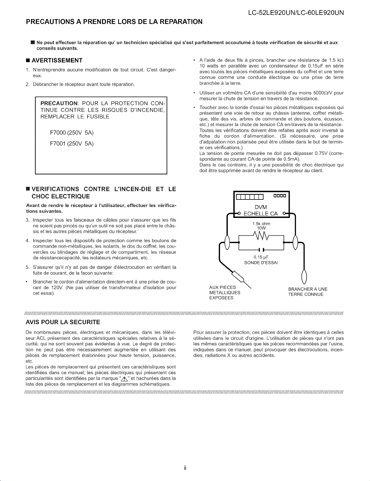
A I'aide de deux ills _ pinces, brancher une r6sistance de 1.5 k__
10 watts en parall_le avec un condensateur de 0.15f.LF en s@ie
avec toutes les pi_ces m6talliques expos6es du coffret et une terre
connue comme une conduite 61ectrique ou une prise de terre
branchee _ la terre.
Utiliser un voltm_tre CA d'une sensibilit6 d'au moins 5000_dV pour
mesurer la chute de tension en travers de la r6sistance.
Toucher avec la sonde d'essai les pi6ces m6talliques expos6es qui
pr6sentent une vole de retour au chassis (antenne, coffret m6talli-
que, t6te des vis, arbres de commande et des boutons, 6cusson,
etc.) et mesurer la chute de tension CA en-travers de la r6sistance.
Toutes les v@ifications doivent 6tre refaites apr6s avoir invers6 la
fiche du cordon d'alimentation. (Si necessaire, une prise
d'adpatation non polaris6e peut _tre utilis6e dans le but de termin-
er ces v@ifications.)
La tension de pointe mesur6e ne dolt pas depasser 0.75V (corre-
spondante au courant CA de pointe de 0.5mA).
Dans le cas contraire, il y a une possibilit6 de choc 61ectrique qui
dolt _tre supprim6e avant de rendre le r6cepteur au client.
l-i-i-i-i-i-i oooo i
DVM |
ECHELLE CA o1"-1
1.5k ohm /
AUX PIECES \
METALLIQUES TERRE CONNUE
EXPOSEES
BRAN( ;HER A UNE
_____________________________________________________________________________________________________________________________________________________________________________________________________________________________________________
AVIS POUR LA SECURITE
De nombreuses pi6ces, electriques et m6caniques, dans les t616vi-
seur ACL pr6sentent des caract@istiques sp6ciales relatives _ la s6-
curit6, qui ne sont souvent pas 6videntes _ vue. Le degr6 de protec-
tion ne peut pas 6tre n6cessairement augment6e en utilisant des
pi6ces de remplacement 6talonn6es pour haute tension, puissance,
etc.
Les pi_ces de remplacement qui pr6sentent ces caract@istiques sont
identifi6es dans ce manuel; les pi_ces 61ectriques qui presentent ces
particularit6s sont identifiees par la marque "Z_" et hachur_es dans la
liste des pi_ces de remplacement et les diagrammes sch_matiques.
_____________________________________________________________________________________________________________________________________________________________________________________________________________________________________________
Pour assurer la protection, ces pi_ces doivent @re identiques _ celles
utilis_es dans le circuit d'origine. L'utilisation de pi_ces qui n'ont pas
les m_mes caract@istiques que les pi_ces recommand_es par I'usine,
indiqu_es dans ce manuel, peut provoquer des _lectrocutions, incen-
dies, radiations X ou autres accidents.
LC-52LE920UN/LC-60LE920UN
PRECAUTIONS FOR USING LEAD-FREE SOLDER
='Employing lead-free solder
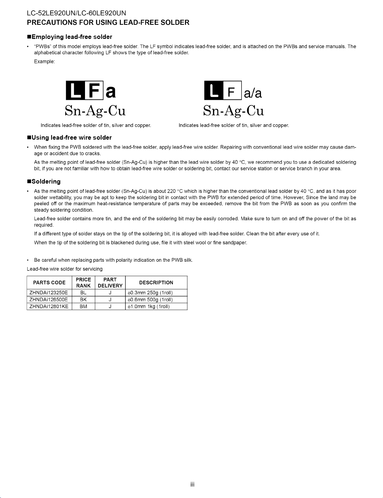
"PWBs" of this model employs lead-free solder. The LF symbol indicates lead-free solder, and is attached on the PWBs and service manuals. The
alphabetical character following LF shows the type of lead-free solder.
Example:
a a/a
Sn-Ag-Cu
Indicates lead-free solder of tin, silver and copper.
Indicates lead-free solder of tin, silver and copper.
Sn-Ag-Cu
='Using lead-free wire solder
When fixing the PWB soldered with the lead-free solder, apply lead-free wire solder. Repairing with conventional lead wire solder may cause dam-
age or accident due to cracks.
As the melting point of lead-free solder (Sn-Ag-Cu) is higher than the lead wire solder by 40 °C, we recommend you to use a dedicated soldering
bit, if you are not familiar with how to obtain lead-free wire solder or soldering bit, contact our service station or service branch in your area.
='Soldering
As the melting point of lead-free solder (Sn-Ag-Cu) is about 220 °C which is higher than the conventional lead solder by 40 °C, and as it has poor
solder wettability, you may be apt to keep the soldering bit in contact with the PWB for extended period of time. However, Since the land may be
peeled off or the maximum heat-resistance temperature of parts may be exceeded, remove the bit from the PWB as soon as you confirm the
steady soldering condition.
Lead-free solder contains more tin, and the end of the soldering bit may be easily corroded. Make sure to turn on and off the power of the bit as
required.
If a different type of solder stays on the tip of the soldering bit, it is alloyed with lead-free solder. Clean the bit after every use of it.
When the tip of the soldering bit is blackened during use, file it with steel wool or fine sandpaper.
Be careful when replacing parts with polarity indication on the PWB silk.
Lead-free wire solder for servicing
PARTS CODE
ZHNDAi123250E BL J
ZHNDAi126500E BK J
ZHNDAi12801KE BM J
PRICE PART
RANK DELIVERY
DESCRIPTION
#0.3mm 250g (1roll)
#0.6mm 500g (1roll)
#1.0mm lkg (1roll)

OUTLINE
MAJOR SERVICE PARTS
mPWB UNIT
Ref No. Part No. Discription
N DKEYMF452FM20 MAIN Unit*l
N DUNTKF493FM01 ICON Unit
N DUNTKF493FM02 LOGO Unit
N DUNTKF494FM01 R/C, LED Unit
N RUNTKA690WJQZ TOUCH SENSOR Unit*2
N RDENCA395WJQZ POWER Unit
N RUNTK4570TPZA LCD CONTROL Unit
N RUNTK4433TPZA LED DRIVE Unit (LC-52LE920UN)
N RUNTK4433TPZZ LED DRIVE Unit (LC-60LE920UN)
NOTE: "1
mOTHER UNIT
Replace MAIN PWB Units (DKEYMF452FM20) in case of IC8455, IC8401 or IC3302 failure.
*2
TOUCH SENSOR Unit (RUNTKA690WJQZ) reuse will be impossible, once it is stuck on front glass and exfoliates.
Therefore, please exchange of a touch sensor unit in the case of front glass exchange.
Ref No. Part No. Description
N R1LK520D3LWB0Z 52" LCD Panel Module Unit (LK520D3LWB0Z) (LC-52LE920UN)
N R1LK600D3LW30Z 60" LCD Panel Module Unit (LK600D3LW30Z) (LC-60LE920UN)
LC-52LE920UN/LC-60LE920UN
talC FOR EXCLUSIVE USE OF THE SERVICE
Ref No. Part No. Description Q'ty
IC509 VHiR24002AS1YS R1EX24002ASAS0A RGB EDID 1
IC2002 RH-iXC786WJNHQ R5F364A6NFB Monitor Microcomputer 1
==SERVICE JIGS
Ref No. Part No. Discription Q'ty
N QCNW-C222WJQZ Connecting Cord L=1000mm 80pin LCD Control Unit to LCD Panel Unit 2
N QCNW-H184WJQZ Connecting Cord L=1000mm 12pin Main to Power Unit (PD) 1
N QCNW-F676WJQZ Connecting Cord L=1000mm 41pin Main to LCD Control Unit (LW) 1
N QCNW-G405WJQZ Connecting Cord L=1000mm 4pin Power to LCD Control Unit (PL) 1
N QCNW-G394WJQZ Connecting Cord L=1000mm 9pin Main to LED Drive Unit (LB) 1
N QCNW-K593WJQZ Connecting Cord L=1000mm 13pin Power to LED Drive Unit (LA) 1
iv
LC-52LE920UN/LC-60LE920UN
CHAPTER 1. SPECIFICATIONS
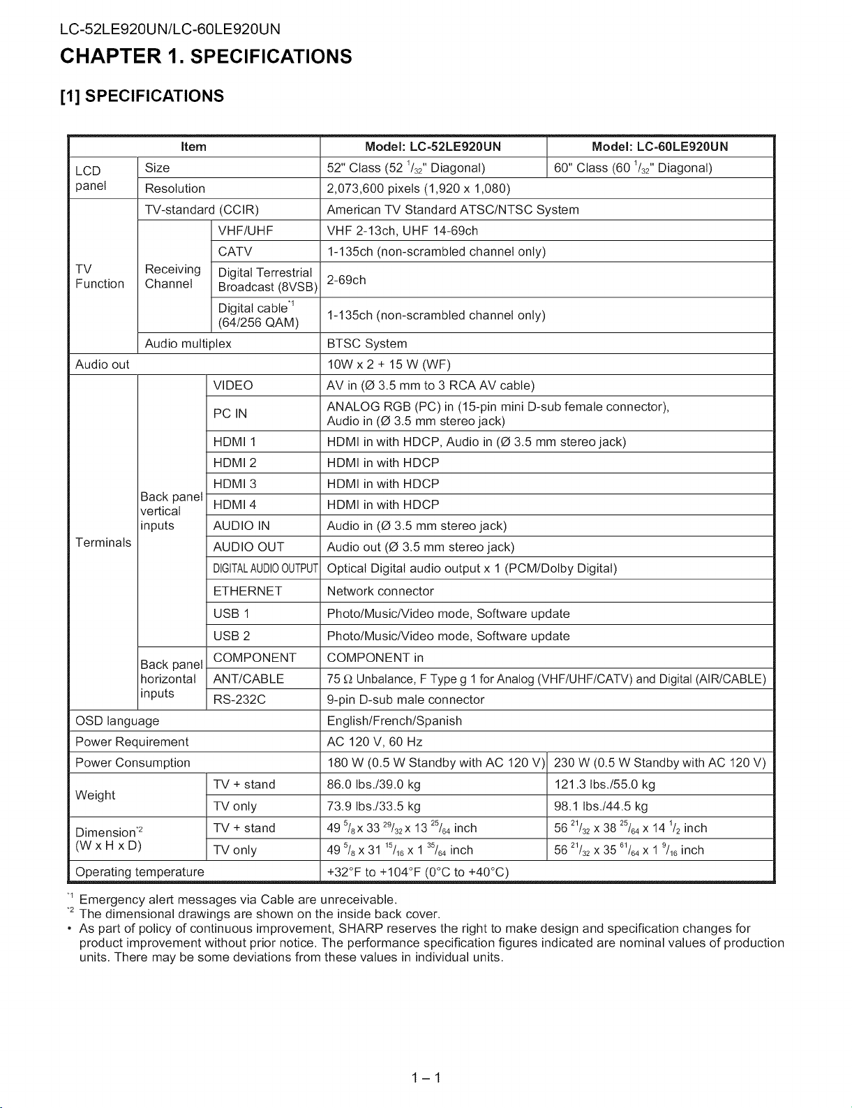
[1] SPECIFICATIONS
Item
LCD
panel
TV
Function
Audio out
Terminals
OSD language
Power Requirement
Power Consumption
Weight
Dimension .2
(WxHxD)
Operating temperature +32°F to +104°F (0°C to +40°C)
Size
Resolution
TV-standard (CCIR)
VHF/UHF
CATV
Receiving Digital Terrestrial
Channel Broadcast (8VSB)
Digital cable .1
(64/256 QAM)
Audio multi )lex
VIDEO
PC IN
HDMI 1
HDMI 2
HDMI 3
Back panel
vertical
inputs
Back panel
horizontal
inputs
HDMI 4
AUDIO IN
AUDIO OUT
DIGITALAUDIOOUTPUT
ETHERNET
USB 1
USB 2
COMPONENT
ANT/CABLE
RS-232C
TV + stand
TV only
TV + stand
TV only
Model: LC-52LE920UN Model: LC-60LE920UN
52" Class (52 1/32"Diagonal) 60" Class (60 _/32"Diagonal)
2,073,600 pixels (1,920 x 1,080)
American TV Standard ATSC/NTSC System
VHF 2-13ch, UHF 14-69ch
1-135ch (non-scrambled channel only)
2-69ch
1-135ch (non-scrambled channel only)
BTSC System
10W x 2 + 15 W (WF)
AV in (0 3.5 mm to 3 RCA AV cable)
ANALOG RGB (PC) in (15-pin mini D-sub female connector),
Audio in (0 3.5 mm stereo jack)
HDMI in with HDCP, Audio in (0 3.5 mm stereo jack)
HDMI in with HDCP
HDMI in with HDCP
HDMI in with HDCP
Audio in (0 3.5 mm stereo jack)
Audio out (0 3.5 mm stereo jack)
Optical Digital audio output x 1 (PCM/Dolby Digital)
Network connector
Photo/Music/Video mode, Software update
Photo/Music/Video mode, Software update
COMPONENT in
75 _ Unbalance, F Type g 1 for Analog (VHF/UHF/CATV)and Digital (AIR/CABLE)
9-pin D-sub male connector
English/French/Spanish
AC 120 V, 60 Hz
180 W (0.5 W Standby with AC 120 V 230 W (0.5 W Standby with AC 120 V)
86.0 Ibs./39.0 kg 121.3 Ibs./55.0 kg
73.9 Ibs./33.5 kg 98.1 Ibs./44.5 kg
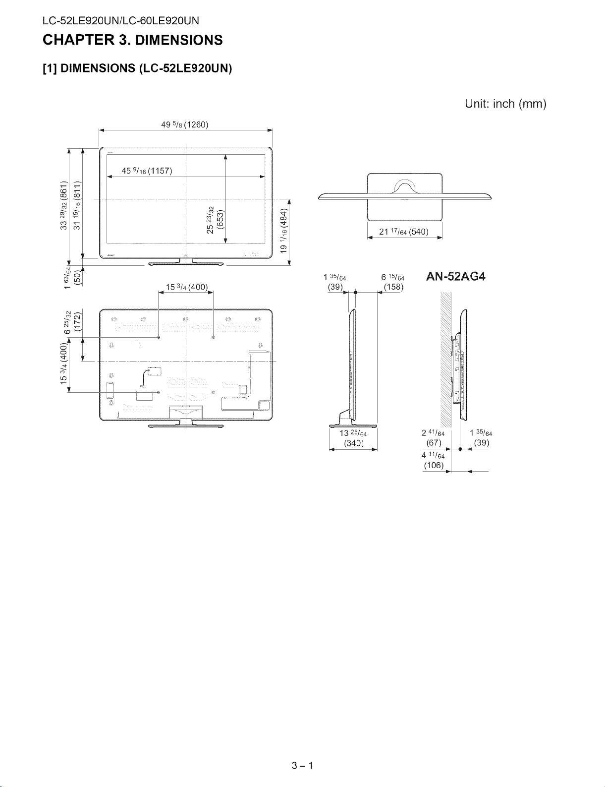
49 5/8x33 29/32x13 25/64inch 56 2_/32x 38 25/64x 14 _/2inch
49 5/8x 31 _5/16x 1 35/64inch 56 2_/32x 35 6_/64x 1 9/_6inch
-1 Emergency alert messages via Cable are unreceivable.
*2The dimensional drawings are shown on the inside back cover.
, As part of policy of continuous improvement, SHARP reserves the right to make design and specification changes for
product improvement without prior notice. The performance specification figures indicated are nominal values of production
units. There may be some deviations from these values in individual units.
1-1
CHAPTER 2. OPERATION MANUAL
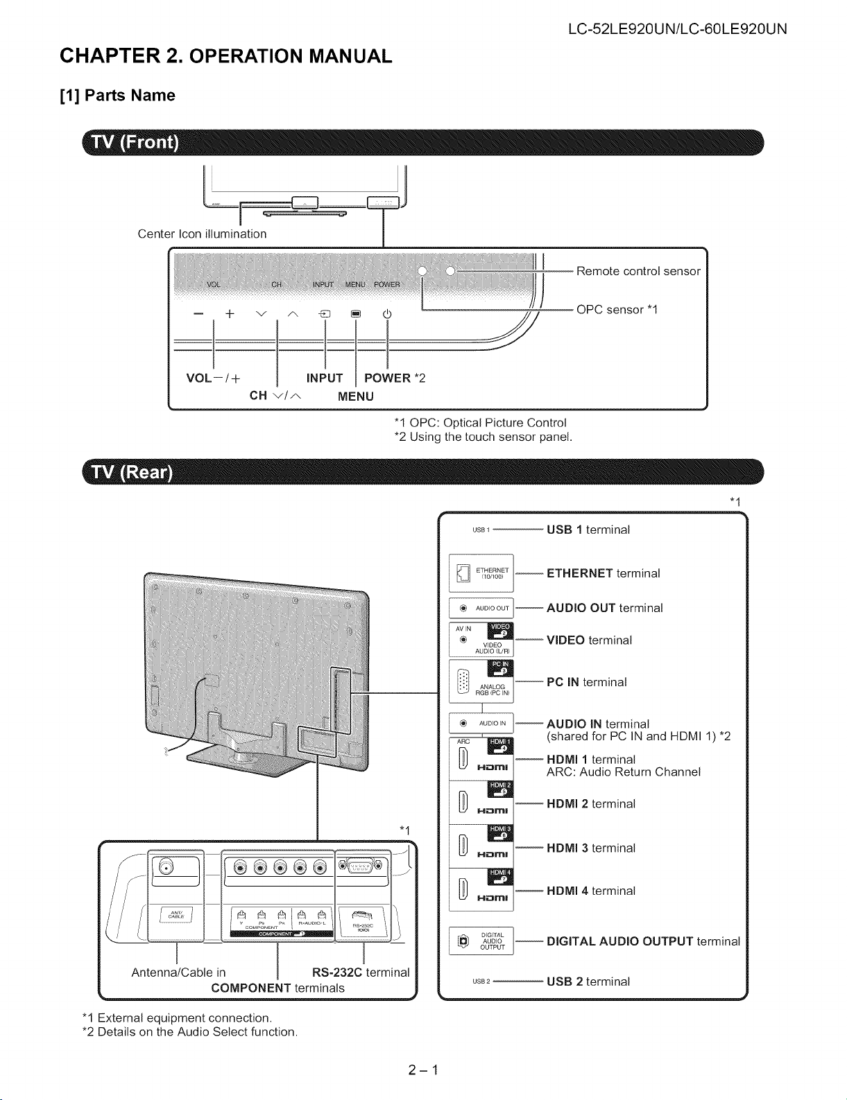
[1] Parts Name
Center Ic°n illumin!ti°n"_ _" !
VOL--/+ NPUT POWER 2
OH v/A MENU
LC-52LE920UN/LC-60LE920UN
Remote control sensor
OPC sensor "I
"10PC: Optical Picture Control
*2 Using the touch sensor panel.
%
Antenna/Cable in 1 RS-232C terminal
COMPONENT terminals
usB_ USB 1 terminal
(10/100)
ETHERNET --
_} AUDIO OUT
® VIDEO _
AUDIO (L/R)
ANALOG
ETHERNET terminal
AUDIO OUT terminal
VIDEO terminal
PC IN terminal
I
AUDIO IN
AUDIO IN terminal
(shared for PC IN and HDMI I) *2
HDMI 1 terminal
ARC: Audio Return Channel
HDMI 2 terminal
"1
HDMI 3 terminal
D H_rlrH _
AUO,O-- DIGITAL AUDIO OUTPUT termina
DIGITAL J
OUTPUT
HDMI 4 terminal
usB2 USB 2 terminal
"1 External equipment connection.
*2 Details on the Audio Select function.
2-1
LC-52LE920UN/LC-60LE920UN
1
I 18
TV STB DVD'VCRAUDIO
3_
4 OPTION SLEEP PAOIWEGR 20
5 _ .....................................................21
7
8
g
11
12
13
14
15
iii_i
ii,iFAV0R,TE_--FAVAPP3--qo
16
17_
° 19
OREC
22
APPS
27
_28
2g
1
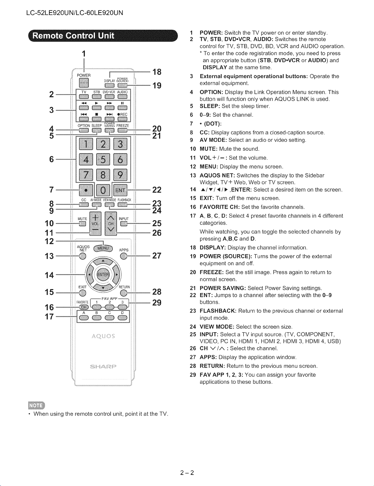
POWER: Switch the TV power on or enter standby.
2
TV, STB, DVD.VCR, AUDIO: Switches the remote
control for TV, STB, DVD, BD, VCR and AUDIO operation.
* To enter the code registration mode, you need to press
an appropriate button (STB, DVD.VCR or AUDIO) and
DISPLAY at the same time.
External equipment operational buttons: Operate the
external equipment.
OPTION: Display the Link Operation Menu screen. This
button will function only when AQUOS LINK is used.
5
SLEEP: Set the sleep timer.
6
0-9: Set the channel.
7
, (DOT):
8
CC: Display captions from a closed-caption source.
9
AV MODE: Select an audio or video setting.
10
MUTE: Mute the sound.
11
VOL +/- : Set the volume.
12
MENU: Display the menu screen.
13
AQUOS NET: Switches the display to the Sidebar
Widget, TV + Web, Web or TV screen.
14
A/T/_ / I_ ,ENTER: Select a desired item on the screen.
15
EXIT: Turn off the menu screen.
16
FAVORITE OH: Set the favorite channels.
17
A, B, C, D: Select 4 preset favorite channels in 4 different
categories.
While watching, you can toggle the selected channels by
pressing A,B,C and D.
18
DISPLAY: Display the channel information.
19
POWER (SOURCE): Turns the power of the external
equipment on and off.
20
FREEZE: Set the still image. Press again to return to
normal screen.
21
POWER SAVING: Select Power Saving settings.
22
ENT: Jumps to a channel after selecting with the 0-9
buttons.
23
FLASHBACK: Return to the previous channel or external
input mode.
24
VIEW MODE: Select the screen size.
25
INPUT: Select a TV input source. (TV, COMPONENT,
VIDEO, PC IN, HDMI 1, HDMI 2, HDMI 3, HDMI 4, USB)
26
CH v/A : Select the channel.
27
APPS: Display the application window.
28
RETURN: Return to the previous menu screen.
29
FAV APP 1, 2, 3: You can assign your favorite
applications to these buttons.
, When using the remote control unit, point it at the TV.
2-2
LC-52LE920UN/LC-60LE920UN
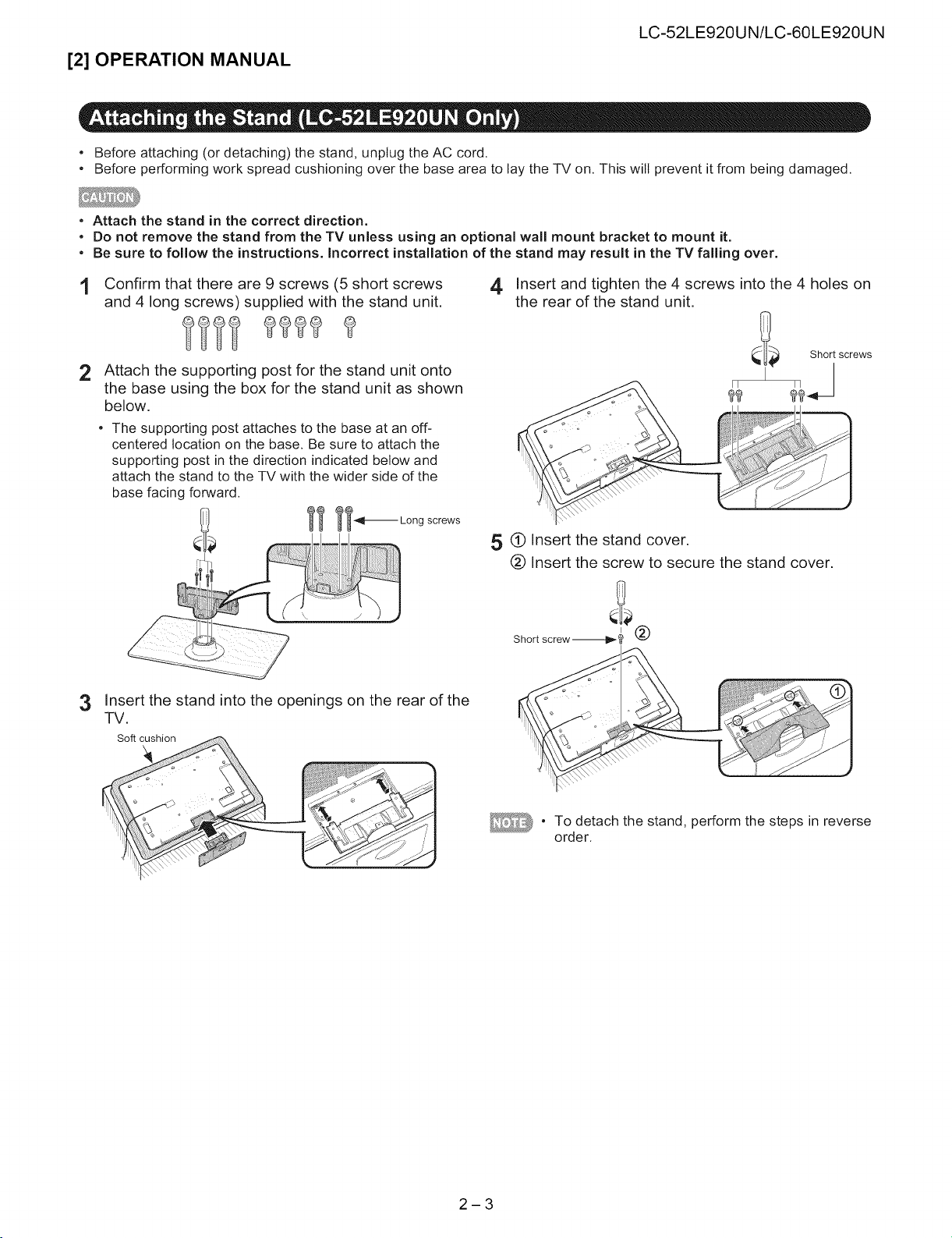
[2] OPERATION MANUAL
° Before attaching (or detaching) the stand, unplug the AC cord.
• Before performing work spread cushioning over the base area to lay the TV on. This will prevent it from being damaged.
• Attach the stand in the correct direction.
• Do not remove the stand from the TV unless using an optional wall mount bracket to mount it.
• Be sure to follow the instructions. Incorrect installation of the stand may result in the TV falling over.
1 Confirm that there are 9 screws (5 short screws 4
and 4 long screws) supplied with the stand unit.
Attach the supporting post for the stand unit onto
2
the base using the box for the stand unit as shown
below.
• The supporting post attaches to the base at an off-
centered location on the base. Be sure to attach the
supporting post in the direction indicated below and
attach the stand to the TV with the wider side of the
base facing forward.
_ _-_11_ Long screws
Insert the stand into the openings on the rear of the
3
TV.
Soft cushion
Insert and tighten the 4 screws into the 4 holes on
the rear of the stand unit.
_it_ Short screws
_9
,5 (_ Insert the stand cover.
(_ Insert the screw to secure the stand cover.
Short screw _!!_
2-3
To detach the stand, perform the steps in reverse
order.
LC-52LE920UN/LC-60LE920UN
CHAPTER 3. DIMENSIONS
[1] DIMENSIONS (LC-52LE920UN)
49 5/8 (1260)
I
459/16(1157) I
_g
O4
Unit: inch (mm)
f
l ]
21 17/64 (540) D,,
_d
_O
#: I _q,
o
I
1 35/64 6 15/64
(39) _ (158)
13 25/64(340)
AN-52AG4
2 41/64 I
4 11/64
(106)_
3-1
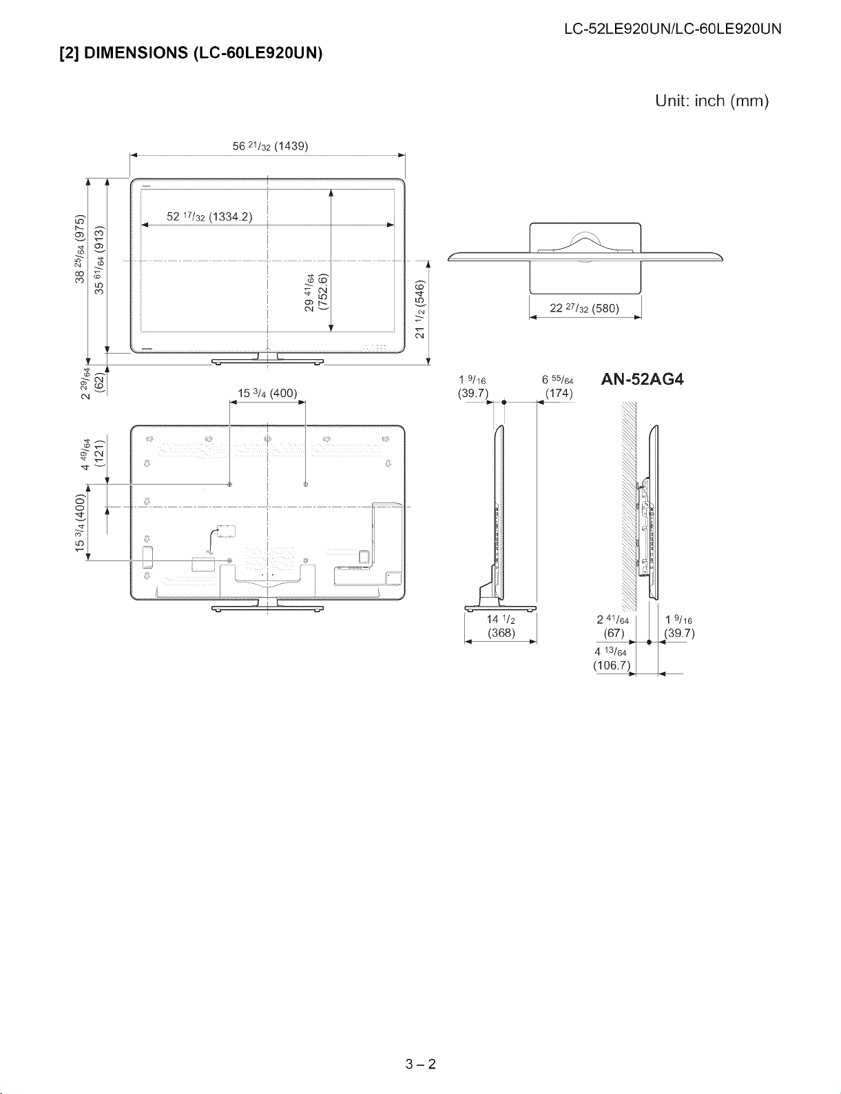
[2] DIMENSIONS (LC-60LE920UN)
56 21/32 (1439)
LC-52LE920UN/LC-60LE920UN
Unit: inch (mm)
(o
LO
cO
o4
LJ i _--
! !
15 3/4 (400)
f
e,
1 9/16 6 55/64
(39.7) (174)
141j2j(368)
t ]
22 27/32 (580)
AN =52AG4
2 41/64 I 1 9/16
_7)
4 13/64
(106.7)
%
3-2
LC-52LE920UN/LC-60LE920UN
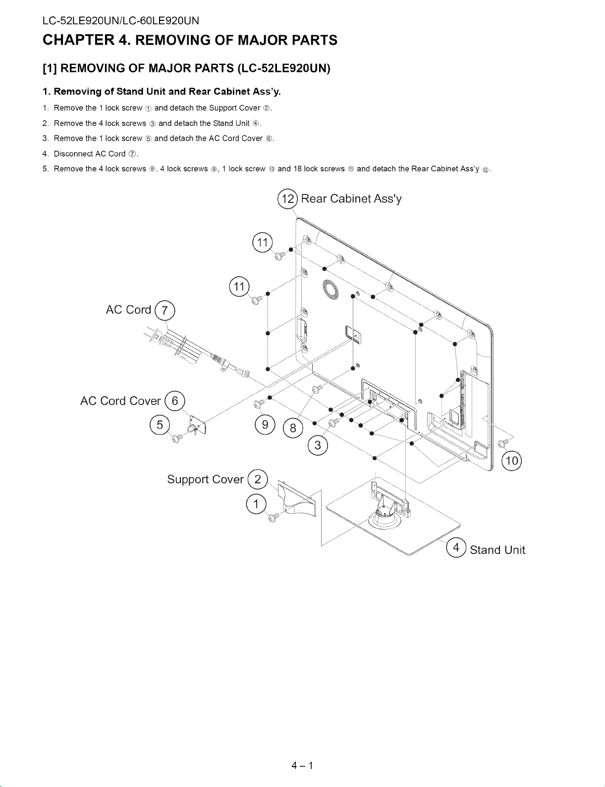
CHAPTER 4. REMOVING OF MAJOR PARTS
[1] REMOVING OF MAJOR PARTS (LC-52LE920UN)
1. Removing of Stand Unit and Rear Cabinet Ass'y.
1. Remove the 1 lock screw _ and detach the Support Cover ®.
2. Remove the 4 lock screws ® and detach the Stand Unit _.
3. Remove the 1 lock screw ® and detach the AC Cord Cover Ch.
4. Disconnect AC Cord _.
5. Remove the 4 lock screws ¢_, 4 lock screws ®, 1 lock screw _0_and 18 lock screws _ and detach the Rear Cabinet Ass'y @.
Rear Cabinet Ass'y
AC Cord Cover (_
Support Cover
Stand Unit
4-1
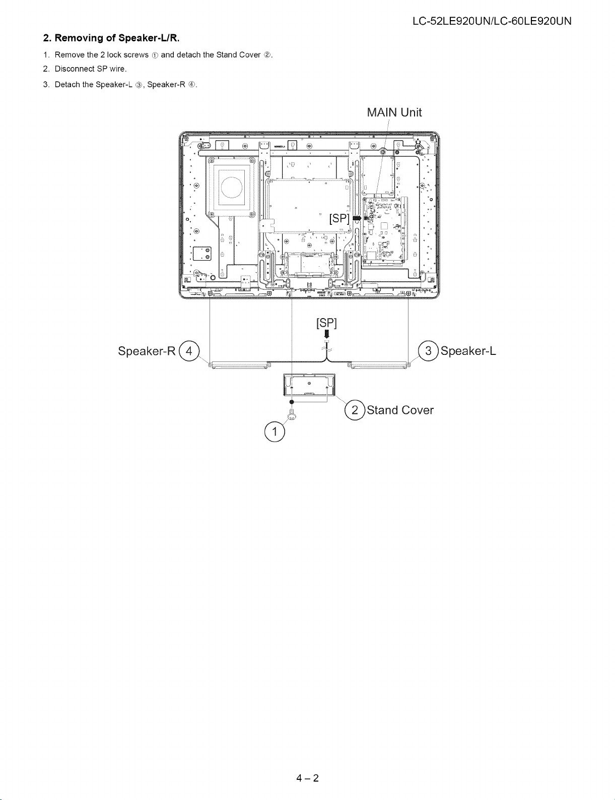
2. Removing of Speaker-L/R.
1. Remove the 2 lock screws d_ and detach the Stand Cover _.
2. Disconnect SP wire.
3. Detach the Speaker-L ®, Speaker-R ®.
LC-52LE920UN/LC-60LE920UN
MAiN Unit
Speaker-R (_.
[sP]
I!
_) Speaker-L
Cover
©
4-2
LC-52LE920UN/LC-60LE920UN
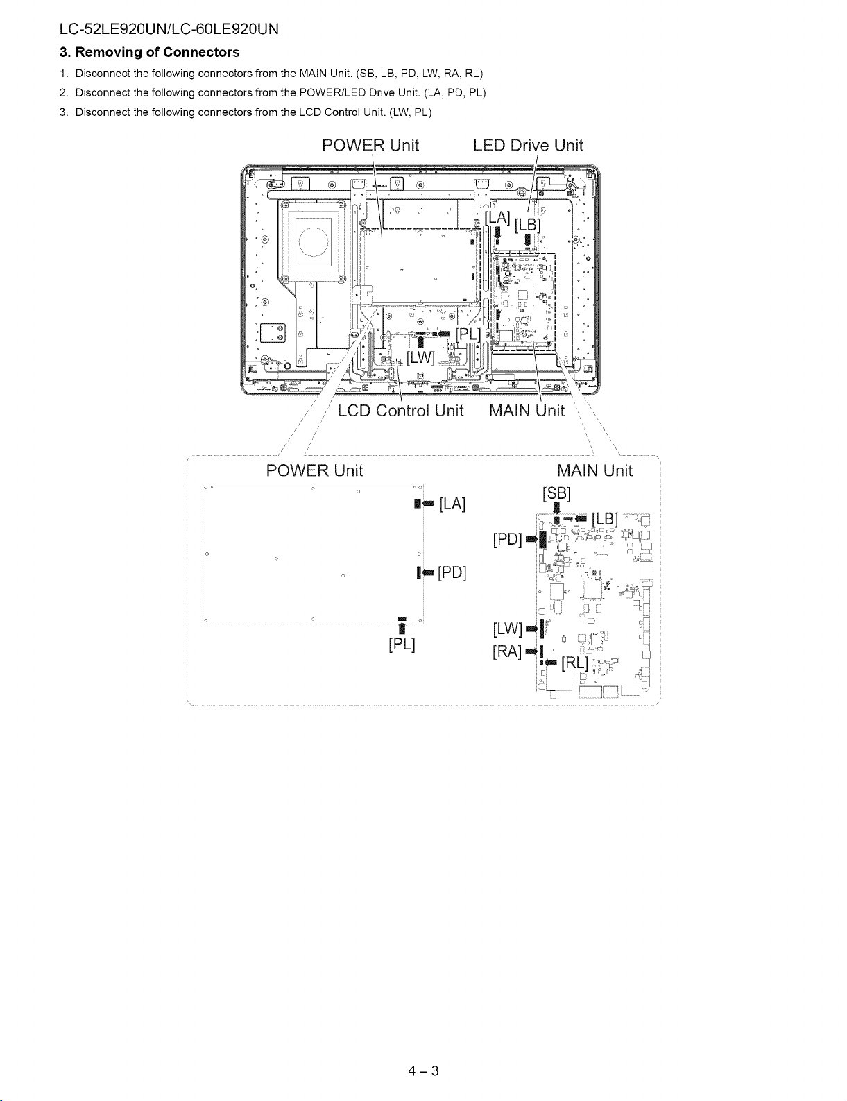
3. Removing of Connectors
1. Disconnect the following connectors from the MAIN Unit. (SB, LB, PD, LW, RA, RL)
2. Disconnect the following connectors from the POWER/LED Drive Unit. (LA, PD, PL)
3. Disconnect the following connectors from the LCD Control Unit. (LW, PL)
POWER Unit MAIN Unit
o o[
m_,,[LA]
o
[SB]
I_ [PD]
[PL]
4-3
LC-52LE920UN/LC-60LE920UN
4. Removing
1. Remove
2. Remove
3. Remove
4. Remove
5. Remove
6. Remove
7. Remove the
8. Remove the
9. Remove the
10.Remove the
11.Remove the
12.Remove the
13.Remove the
14.Remove the
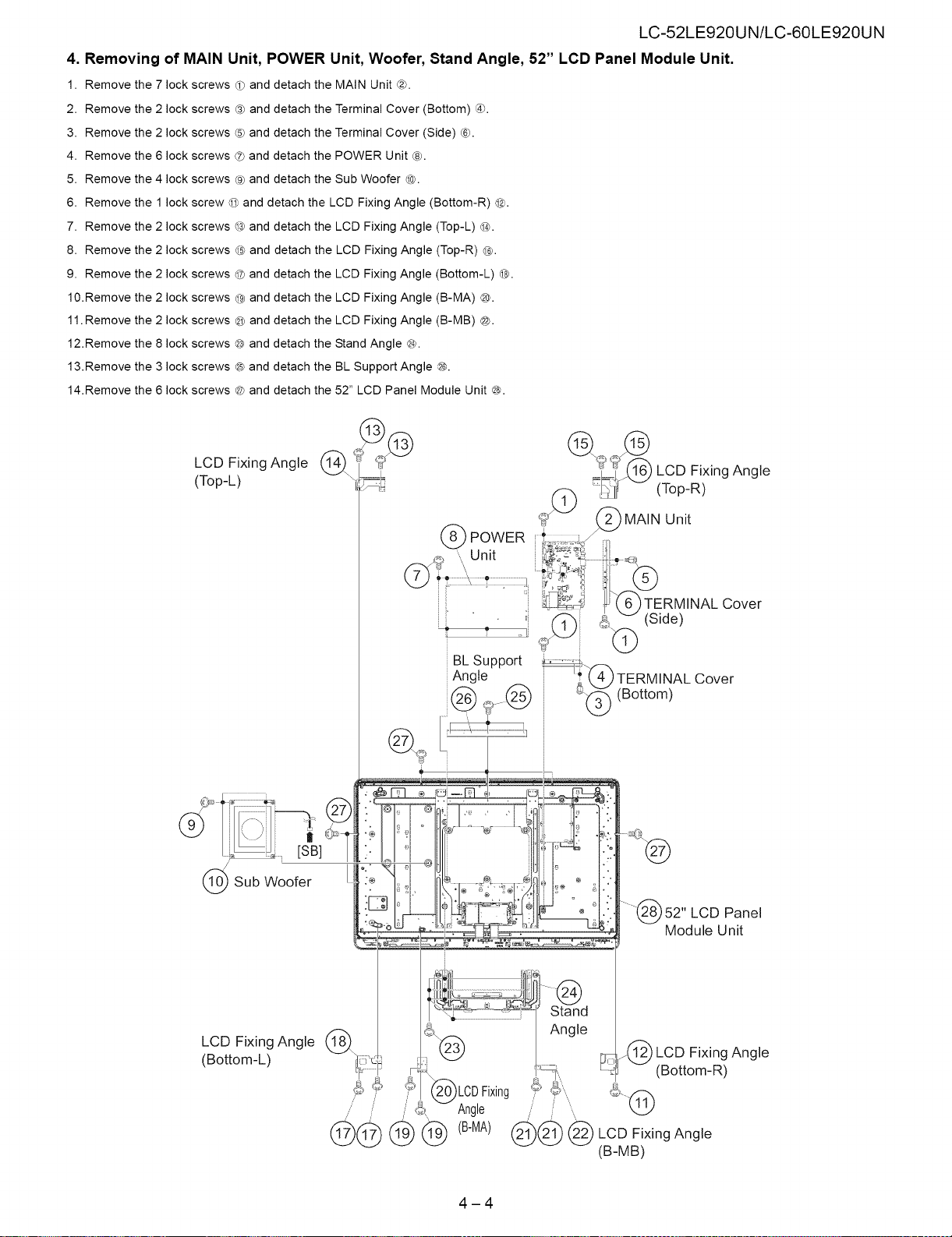
the 7 lock screws d) and detach the MAIN Unit @.
the 2 lock screws @ and detach the Terminal Cover (Bottom) ®.
the 2 lock screws ® and detach the Terminal Cover (Side) ®.
the 6 lock screws ® and detach the POWER Unit ®.
the 4 lock screws ® and detach the Sub Woofer @.
the 1 lock screw © and detach the LCD Fixing Angle (Bottom-R) @.
of MAIN Unit, POWER Unit, Woofer, Stand Angle, 52" LCD Panel Module Unit.
2 lock screws @ and detach the LCD Fixing Angle (Top-L) @.
2 lock screws @ and
2 lock screws @ and
2 lock screws @ and
2 lock screws ® and
8 lock screws @ and
3 lock screws ® and
6 lock screws @ and
detach the LCD Fixing Angle (Top-R) @.
detach the LCD Fixing Angle (Bottom-L) @.
detach the LCD Fixing Angle (B-MA) ®.
detach the LCD Fixing Angle (B-MB) @.
detach the Stand Angle @.
detach the BL Support Angle @.
detach the 52" LCD Panel Module Unit @.
I
LCD Fixing Angle _\
(Top-L) _i
1_/1_f_5 LCD Fixing Angle
(Top-R)
Sub Woofer
LCD
Fixing Angle
(Bottom-L)
BL Support
Angle
tLCDFixing
Angle
(B-MA)
8' Module Unit
Stand
Angle
_-j @LOD Fixing Angle
_@ @ LCD Fixing Angle
(B-MB)
52" LCD Panel
(Bottom-R)
Cover
4-4
LC-52LE920UN/LC-60LE920UN
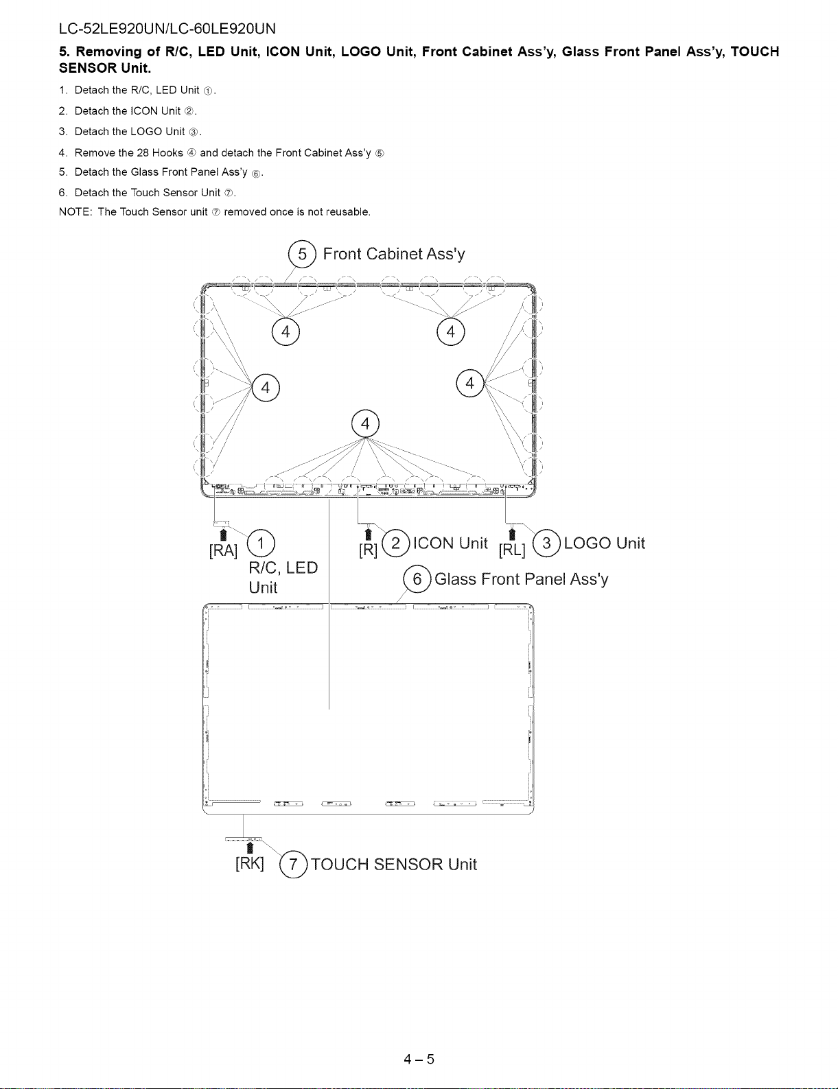
5. Removing of RIO, LED Unit, ICON Unit, LOGO Unit, Front Cabinet Ass'y, Glass Front Panel Ass'y, TOUCH
SENSOR Unit.
1. Detach the R/C, LED Unit _).
2. Detach the ICON Unit ®.
3. Detach the LOGO Unit _).
4. Remove the 28 Hooks _) and detach the Front Cabinet Ass'y (57
5. Detach the Glass Front Panel Ass'y ®).
6. Detach the Touch Sensor Unit _7._.
NOTE: The Touch Sensor unit (t) removed once is not reusable.
i_ \/
/
[RIAi'_ -_ ICON Unit [Rt]_) LOGO Unit
R/C, LEDUnit Glass Front Panel Ass'y
1_...................... ........................] ................................................J f........................ ........................J
/
t
[RK] "(_)TOUCH SENSOR Unit
4-5
LC-52LE920UN/LC-60LE920UN
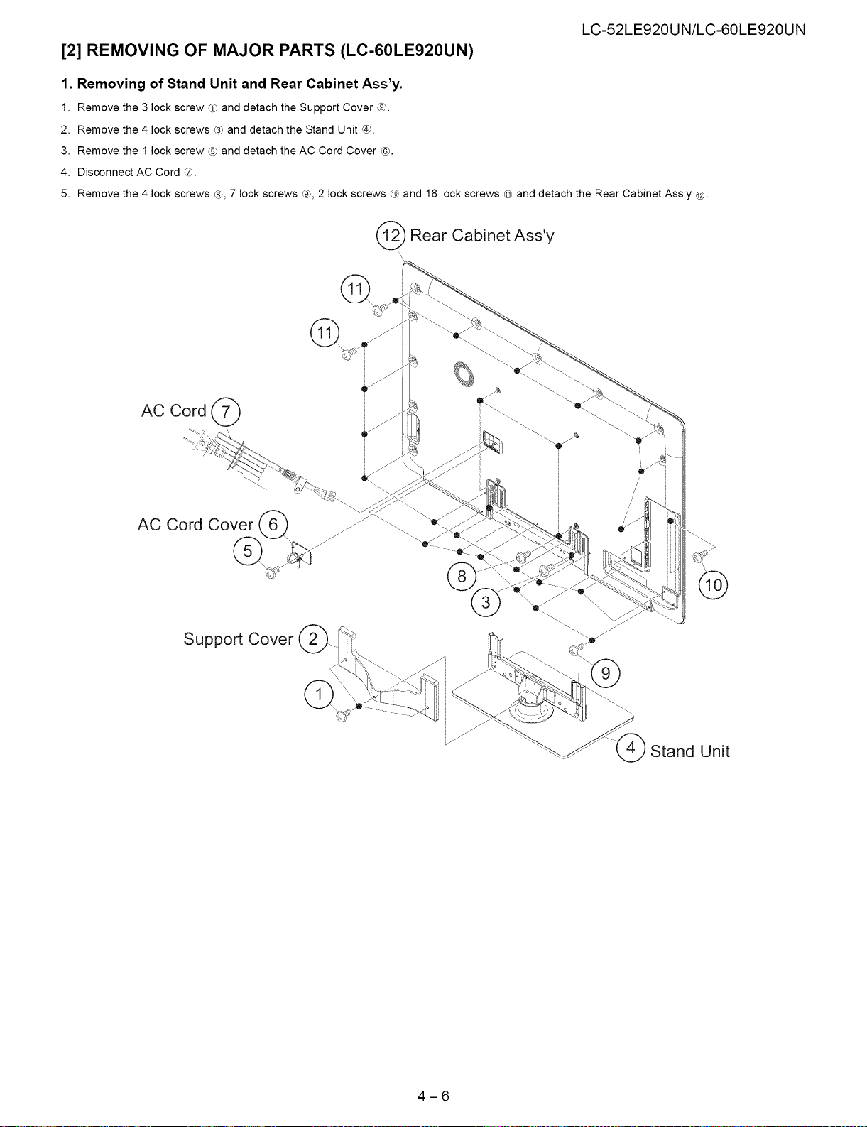
[2] REMOVING OF MAJOR PARTS (LC-60LE920UN)
1. Removing of Stand Unit and Rear Cabinet Ass'y.
1. Remove the 3 lock screw _ and detach the Support Cover _2_.
2. Remove the 4 lock screws ® and detach the Stand Unit #_.
3. Remove the 1 lock screw ® and detach the AC Cord Cover ®.
4. Disconnect AC Cord ®.
5. Remove the 4 lock screws ¢_, 7 lock screws ®7,2 lock screws _ and 18 lock screws @ and detach the Rear Cabinet Ass'y @.
Rear Cabinet Ass'y
\
\
@
AC Cord Cover __
Support Cover
Stand Unit
4-6
LC-52LE920UN/LC-60LE920UN
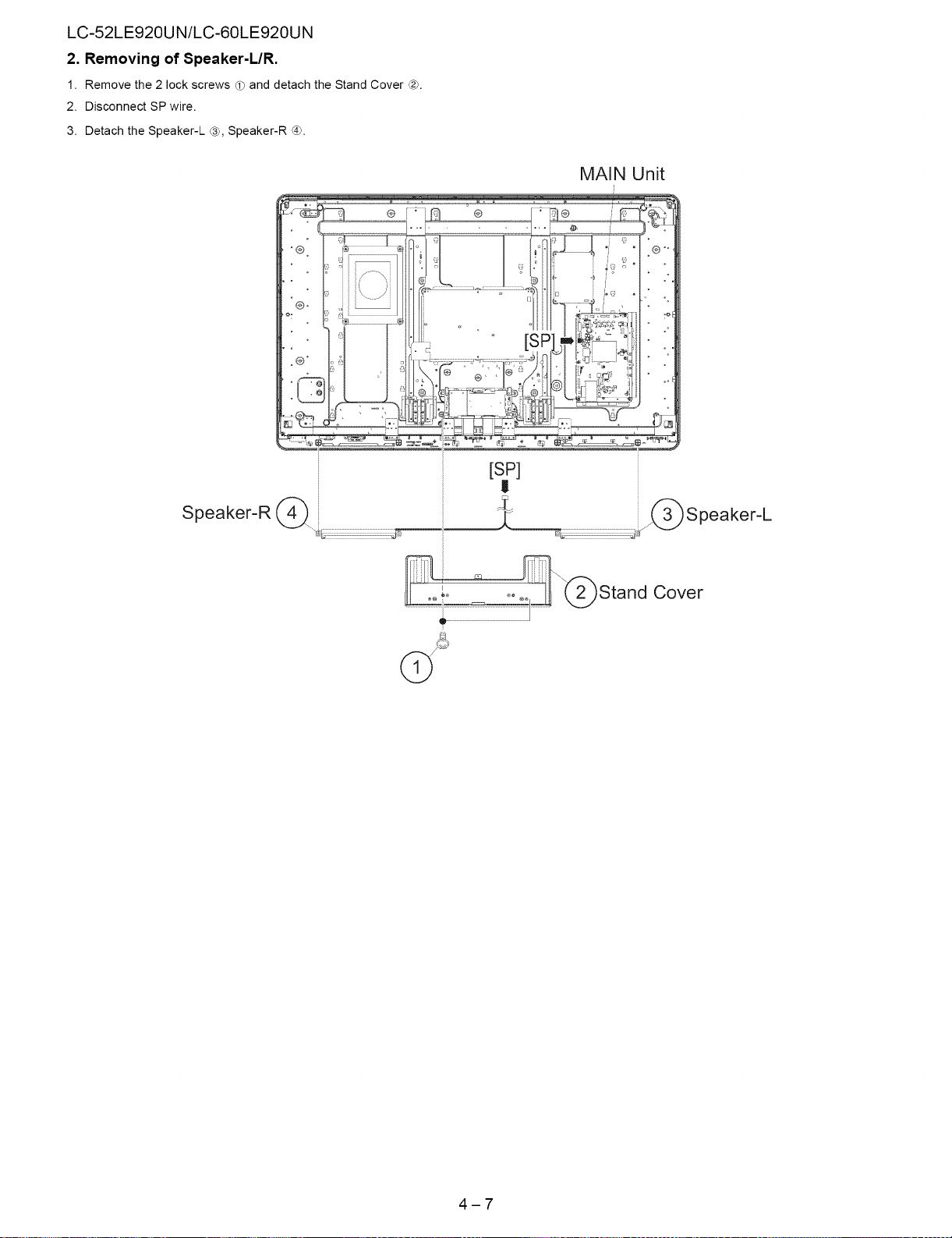
2. Removing of Speaker-L/R.
1. Remove the 2 lock screws d) and detach the Stand Cover _).
2. Disconnect SP wire.
3. Detach the Speaker-L ®, Speaker-R ®.
[SP]
!
Speaker-R (_. :_;..........................................................._
Speaker-L
Cover
t
4-7
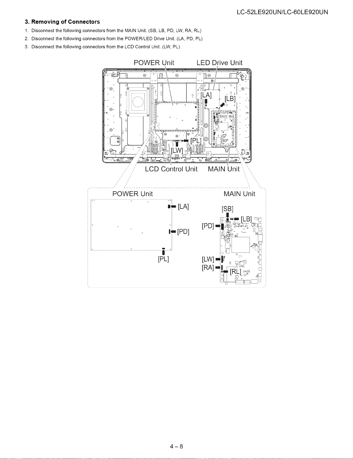
3. Removing of Connectors
1. Disconnect the following connectors from the MAIN Unit. (SB, LB, PD, LW, RA, RL)
2. Disconnect the following connectors from the POWER/LED Drive Unit. (LA, PD, PL)
3. Disconnect the following connectors from the LCD Control Unit. (LW, PL)
POWER Unit LED Drive Unit
POWER Unit
LC-52LE920UN/LC-60LE920UN
\
\
\
\
\
MAIN Unit
m_ [LA]
[PD] .m
,,[PD]
[PL] [LW] u
[RA]
[SB]
4-8
LC-52LE920UN/LC-60LE920UN
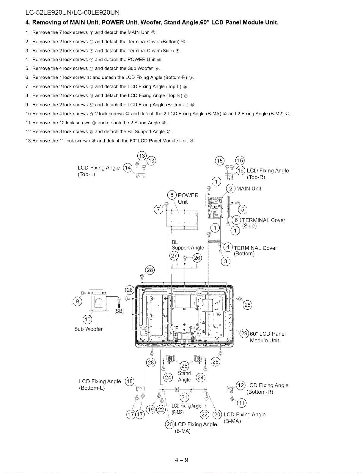
4. Removing of MAIN Unit, POWER Unit, Woofer, Stand Angle,60" LCD Panel Module Unit.
1. Remove the 7 lock screws d) and detach the MAIN Unit _).
2. Remove
3. Remove
4. Remove
5. Remove
6. Remove
7. Remove
8. Remove
9. Remove
10.Remove
11.Remove
12.Remove
13.Remove
the 2 lock
the 2 lock
the 6 lock
the 4 lock
the 1 lock
the 2 lock
the 2 lock
the 2 lock
the 4 lock screws @ 2 lock screws @ and detach the 2 LCD Fixing Angle (B-MA) ® and 2 Fixing Angle (B-M2) _.
the 12 lock screws @ and detach the 2 Stand Angle ®.
the 3 lock screws @ and detach the BL Support Angle ©.
the 11 lock screws @ and detach the 60" LCD Panel Module Unit @.
screws ® and detach the Terminal Cover (Bottom) ®.
screws ® and detach the Terminal Cover (Side) ®.
screws ® and detach the POWER Unit ®.
screws ® and detach the Sub Woofer @.
screw @ and detach the LCD Fixing Angle (Bottom-R) @.
screws @ and detach the LCD Fixing Angle (Top-L) @.
screws @ and detach the LCD Fixing Angle (Top-R) @.
screws @ and detach the LCD Fixing Angle (Bottom-L) @.
LCD
Fixing Angle
(Top-L)
_¢@ @_1_(_ LCD Fixing Angle
(Top-R)
LCD
Fixing Angle _\
(Bottom-L)
)TERMINAL Cover
(Bottom)
60" LCD Panel
Module Unit
,_,1 :_ "-"
Stand ,_
2_ Angle (2_
,1_i) LCD Fixing Angle
_] (Bottom-R)
LCDFixingAngle '\
(B-M2) @ @ LCD Fixing Angle
LCD Fixing Angle (B-MA)
_(B-MA)
4-9
LC-52LE920UN/LC-60LE920UN
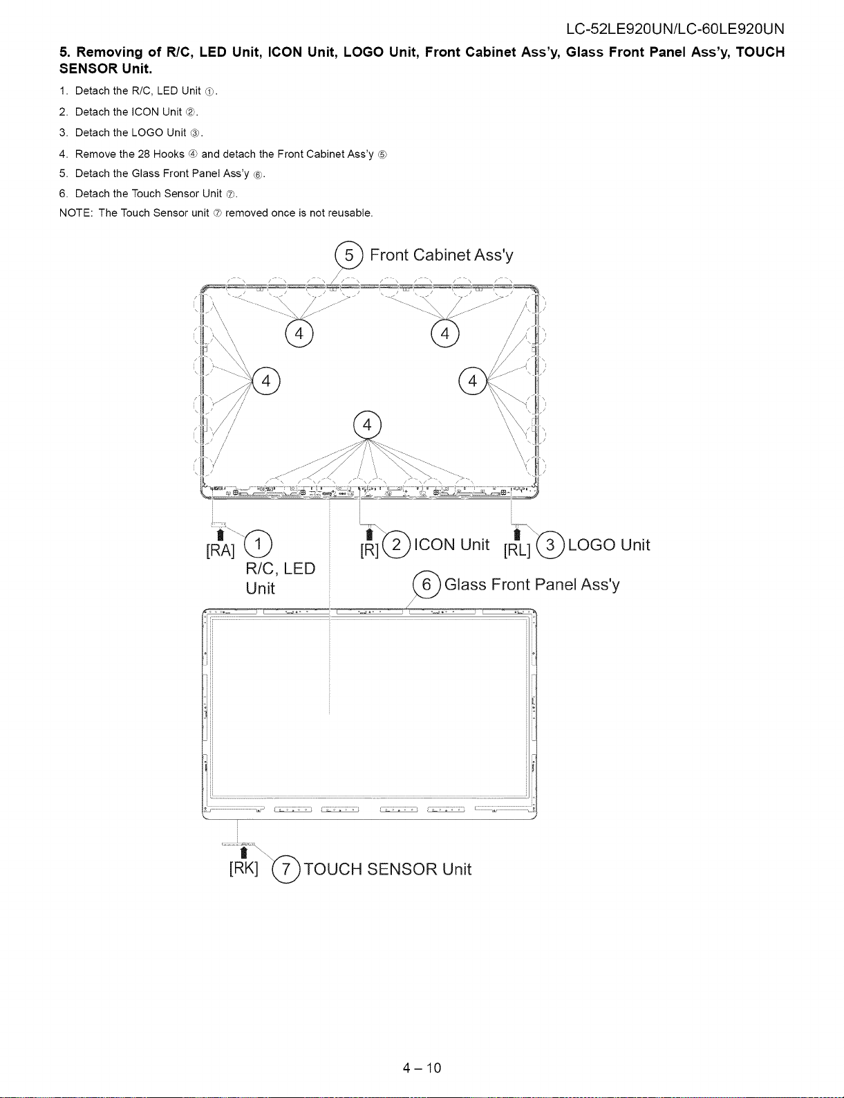
5. Removing of RIO, LED Unit, ICON Unit, LOGO Unit, Front Cabinet Ass'y, Glass Front Panel Ass'y, TOUCH
SENSOR Unit.
1. Detach the R/C, LED Unit _.
2. Detach the ICON Unit ®.
3. Detach the LOGO Unit _}.
4. Remove the 28 Hooks _band detach the Front Cabinet Ass'y @
5. Detach the Glass Front Panel Ass'y ¢_.
6. Detach the Touch Sensor Unit ®.
NOTE: The Touch Sensor unit _hremoved once is not reusable.
(_ Front Cabinet Ass'y
[RIA]"(_) [tR]]c p ICON Unit [RL] "_ LOGO Unit
R/C, LED
Unit _ Glass Front Panel Ass'y
/
:i ............................................... ........................ .............................
_ o , _ o ; _ _ _ , _ ; _ _ o _ _ ; ::::::::::::::::::::::::::::::::
IRK] ('7)TOUCH SENSOR Unit
\d
2
4-10
LC-52LE920UN/LC-60LE920UN
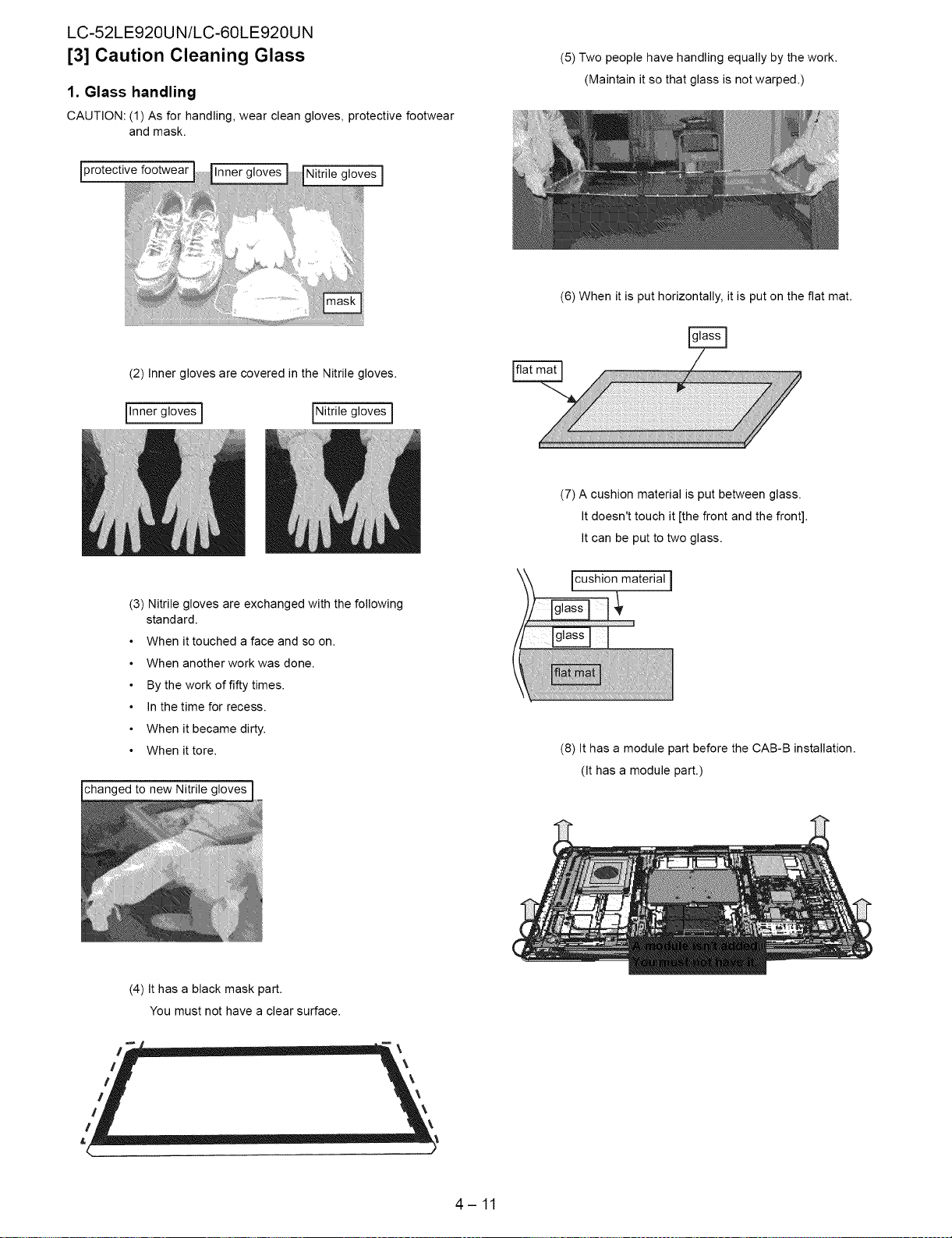
[3] Caution Cleaning Glass
1. Glass handling
CAUTION: (1) As for handling, wear clean gloves, protective footwear
and mask.
protective
(2) Inner gloves are covered in the Nitrile gloves.
[Inner gloves ] INitrile gloves ]
(5) Two people have handling equally by the work.
(Maintain it so that glass is not warped.)
(6) When it is put horizontally, it is put on the flat mat.
(3) Nitrile gloves are exchanged with the following
standard.
When it touched a face and so on.
When another work was done.
By the work of fifty times.
In the time for recess.
When it became dirty.
When it tore.
changed to new Nitrile gloves
(7) A cushion material is put between glass.
It doesn't touch it [the front and the front].
It can be put to two glass.
cushion material ]
(8) It has a module part before the CAB-B installation.
(It has a module part.)
(4) It has a black mask part.
You must not have a clear surface.
\
\
\
\
4-11
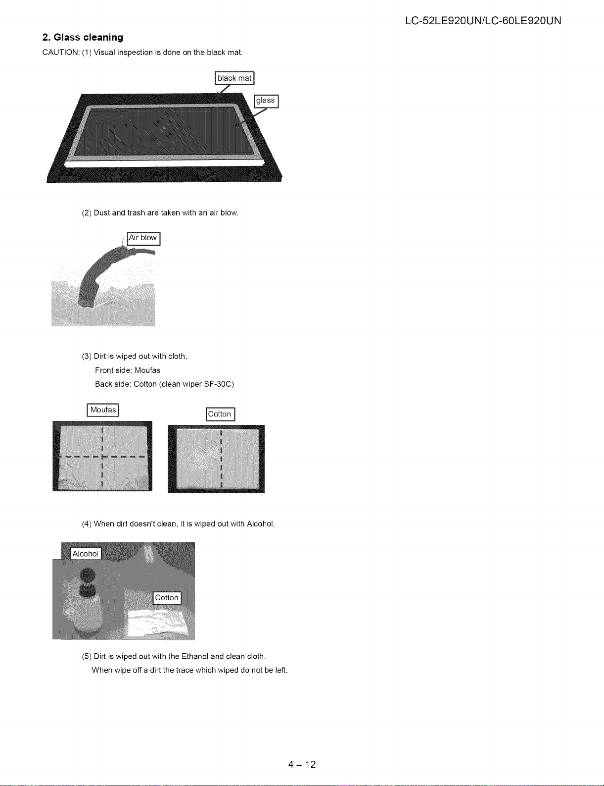
2. Glass cleaning
CAUTION: (1) Visual inspection is done on the black mat.
(2) Dust and trash are taken with an air blow.
LC-52LE920UN/LC-60LE920UN
(3) Dirt is wiped out with cloth.
Front side: Moufas
Back side: Cotton (clean wiper SF-30C)
(4) When dirt doesn't clean, it is wiped out with Alcohol.
(5) Dirt is wiped out with the Ethanol and clean cloth.
When wipe off a dirt the trace which wiped do not be left.
4-12
LC-52LE920UN/LC-60LE920UN
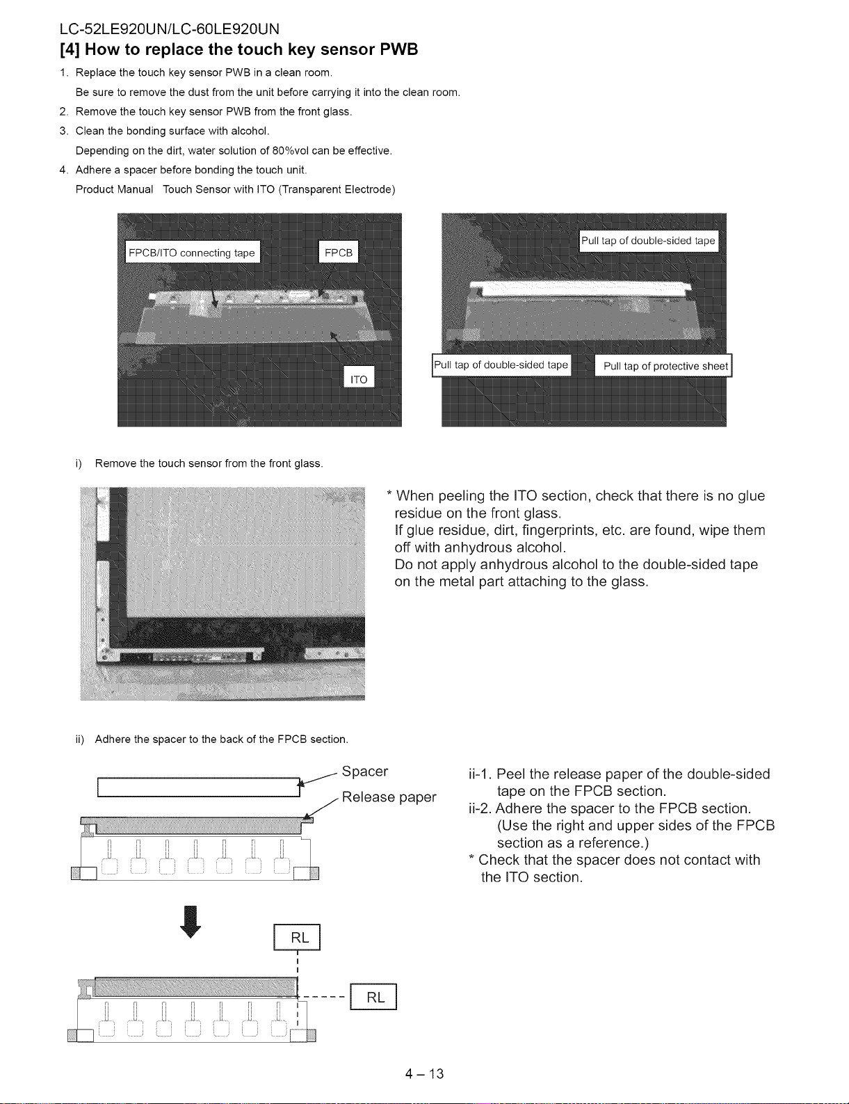
[4] How to replace the touch key sensor PWB
1. Replace the touch key sensor PWB in a clean room.
Be sure to remove the dust from the unit before carrying it into the clean room.
2. Remove the touch key sensor PWB from the front glass.
3. Clean the bonding surface with alcohol.
Depending on the dirt, water solution of 80%vol can be effective.
4. Adhere a spacer before bonding the touch unit.
Product Manual Touch Sensor with ITO (Transparent Electrode)
Pull tap of double-sided tape Pull tap of protective sheet
i) Remove the touch sensor from the front glass.
ii) Adhere the spacer to the back of the FPCB section.
i f.j Space
Release paper
* When peeling the ITO section, check that there is no glue
residue on the front glass.
If glue residue, dirt, fingerprints, etc. are found, wipe them
off with anhydrous alcohol.
Do not apply anhydrous alcohol to the double-sided tape
on the metal part attaching to the glass.
ii-1. Peel the release paper of the double-sided
tape on the FPCB section.
ii-2. Adhere the spacer to the FPCB section.
(Use the right and upper sides of the FPCB
section as a reference.)
* Check that the spacer does not contact with
the ITO section.
!
E
4-13
 Loading...