


 Loading...
R
GS-XP9FGR GS-XP12FGR
GS-XP18FGR
GS-XPM9FGR GS-XPM12FGR
GS-XPM18FGR
Air Conditioner
INDOOR UNIT UNIDAD INTERIOR UNITÀ INTERNA ZIMMERGERÄT UNITE INTERIEURE
∑Ç ÜN∑TE
GS-XP9FGR GS-XPM9FGR GS-XP12FGR GS-XPM12FGR GS-XP18FGR GS-XPM18FGR
FLOOR STANDING
TYPE ROOM AIR CONDITIONER
OPERATION MANUAL
AIRE ACONDICIONADO CONSUELA DE SUELO
MANUAL DE INSTRUCCIONES
CONDIZIONATORE D’ARIA A PAVIMENTO
MANUALE DI ISTRUZIONI
AR CONDICIONADO DE CHÃO
MANUAL DE OPERAÇÃO
CLIMATISEUR SPLIT CONSOLE MURALE
NOTICE D’UTILISATION
TABANDA DURAN T∑P ODA KL∑MASI
KULLANMA KILAVUZU
ENGLISH ESPAÑOL ITALIANO PORTUGUÊS FRANÇAIS TÜRKÇE
*Plasmacluster is trademark of SHARP Corporation.

Attention: Your product is marked with this symbol. It means that used electrical and electronic products should not be mixed with general household waste. There is a separate collection system for these products.
A. Information on Disposal for Users (private households)
1. In the European Union
Attention: If you want to dispose of this equipment, please do not use the ordinary dust bin!
Used electrical and electronic equipment must be treated separately and in accordance with legislation that requires proper treatment, recovery and recycling of used electrical and electronic equipment.
Following the implementation by member states, private households within the EU states may return their used electrical and electronic equipment to designated collection facilities free of charge*. In some countries* your local retailer may also take back your old product free of charge if you purchase a similar new one.
*) Please contact your local authority for further details.
If your used electrical or electronic equipment has batteries or accumulators, please dispose of these separately beforehand according to local requirements.
By disposing of this product correctly you will help ensure that the waste undergoes the necessary treatment, recovery and recycling and thus prevent potential negative effects on the environment and human health which could otherwise arise due to inappropriate waste handling.
2. In other Countries outside the EU
If you wish to discard this product, please contact your local authorities and ask for the correct method of disposal.
For Switzerland: Used electrical or electronic equipment can be returned free of charge to the dealer, even if you don’t purchase a new product. Further collection facilities are listed on the homepage of www.swico.ch or www.sens.ch.
B. Information on Disposal for Business Users.
1. In the European Union
If the product is used for business purposes and you want to discard it:
Please contact your SHARP dealer who will inform you about the take-back of the product. You might be charged for the costs arising from take-back and recycling. Small products (and small amounts) might be taken back by your local collection facilities.
For Spain: Please contact the established collection system or your local authority for take-back of your used products.
2. In other Countries outside the EU
If you wish to discard of this product, please contact your local authorities and ask for the correct method of disposal.
EN

ENGLISH
Thank you for purchasing a SHARP air conditioner. Please read this manual carefully before operating the product.
CONTENTS
...• IMPORTANT SAFETY INSTRUCTIONS |
E-1 |
...........................• ONE-HOUR OFF TIMER |
E-12 |
• PART NAMES ............................................ |
E-3 |
• PLASMACLUSTER OPERATION.............. |
E-13 |
• SETTING DEODORANT FILTERS ............ |
E-5 |
• TIMER OPERATION .................................. |
E-14 |
• USING THE REMOTE CONTROL............. |
E-6 |
• MAIN UNIT OPERATION........................... |
E-16 |
• BASIC OPERATION .................................. |
E-8 |
• MAINTENANCE ......................................... |
E-16 |
• ADJUSTING THE AIR FLOW DIRECTION ...... |
E-10 |
• ADDITIONAL NOTES ON OPERATION .......... |
E-19 |
• AIR OUTLET SELECTION......................... |
E-11 |
• TIPS ON SAVING ENERGY ...................... |
E-19 |
• FULL POWER OPERATION...................... |
E-12 |
• BEFORE CALLING FOR SERVICE........... |
E-20 |
IMPORTANT SAFETY INSTRUCTIONS
WARNINGS FOR USE
1 |
Do not pull or deform the power supply cord. Pulling and misuse of the power supply cord |
can result in damage to the unit and cause electrical shock. |
|
2 |
Be careful not to expose your body directly to the outlet air for a long time. It may affect |
your physical conditions. |
|
3 |
When using the air conditioner for infants, children, elderly, bedridden, or disabled people |
make sure the room temperature is suitable for those in the room. |
|
4 |
Never insert objects into the unit. Inserting objects can result in injury due to the high |
speed rotation of internal fans. |
|
5 |
Ground the air conditioner without fail. Do not connect the grounding wire to gas pipe, |
water pipe, lightning rod or telephone grounding wire. Incomplete grounding may cause |
|
|
electric shock. |
6 |
If anything is abnormal with the air conditioner (ex. a burning smell), stop the operation |
immediately and turn the circuit breaker OFF. |
|
7 |
The appliance shall be installed in accordance with national wiring regulations. Improper |
cable connection can cause the power supply cord, plug and the electrical outlet to |
|
|
overheat and cause fire. |
8 |
If the supply cord is damaged, it must be replaced by the manufacturer or its service agent |
or a similarly qualified person in order to avoid a hazard. Use only the manufacture- |
specified power cord for replacement.
WARNINGS FOR INSTALLATION/REMOVAL/REPAIR
•Do not attempt to install/remove/repair the unit by yourself. Incorrect work will cause electric shock, water leak, fire etc. Consult your dealer or other qualified service personnel for the installation/removal/repair of the unit.
ENGLISH
E-1

IMPORTANT SAFETY INSTRUCTIONS
CAUTIONS FOR USE
1
2 |
Do not operate the buttons with wet hand. It may cause electric shock. |
3 |
For safety, turn the circuit breaker off when not using the unit for an extended period of |
time. |
|
4 |
Check the outdoor unit mounting rack periodically for wear and to make sure it is firmly |
in place. |
|
5 |
Do not put anything on the unit nor step on it. The object or the person may fall down or |
drop, causing injury. |
|
6 |
This unit is designed for residential use. Do not use for other applications such as in a |
kennel or greenhouse to raise animals or grow plants. |
|
7 |
Do not place a vessel with water on the unit. If water penetrates into the unit, electrical |
insulations may deteriorate and cause electric shock. |
|
8 |
Do not block the air inlets nor outlets of the unit. It may cause insufficient performance |
or troubles. |
|
9 |
Be sure to stop the operation and turn the circuit breaker off before performing any |
maintenance or cleaning. A fan is rotating inside the unit and you may get injured. |
10 Do not splash or pour water directly on the unit. Water can cause electrical shock or equipment damage.
11 This appliance is not intended for use by young children or infirm persons without supervision.
Young children should be supervised to ensure that they do not play with the appliance.
CAUTIONS FOR LOCATION/INSTALLATION
•Make sure to connect the air conditioner to power supply of the rated voltage and frequency.
Use of a power supply with improper voltage and frequency can result in equipment damage and possible fire.
•Do not install the unit in a place where inflammable gas may leak. It may cause fire. Install the unit in a place with minimal dust, fumes and moisture in the air.
•Arrange the drain hose to ensure smooth drainage. Insufficient drainage may cause wetting of the room, furniture etc.
•Make sure a leak breaker or a circuit breaker is installed, depending on the installation location, to avoid electrical shock.
E-2
PART NAMES
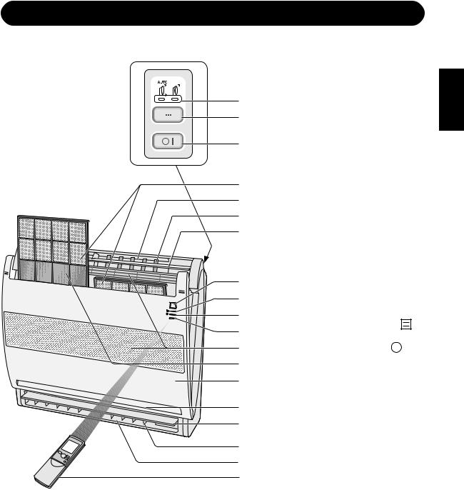
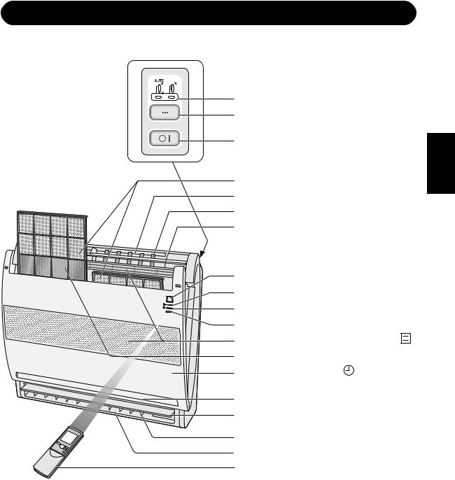
INDOOR UNIT
1 |
1 AIR OUTLET SELECTION |
||||
2 |
Lamp (green) |
|
|||
|
|
|
|
||
3 |
2 AIR OUTLET SELECTION |
||||
button |
|
||||
|
3 POWER. Button |
|
|||
4 |
4 Air Filters |
|
|||
5 |
|
||||
|
|
|
|
||
6 |
5 Upper air outlet |
|
|||
7 |
6 Horizontal Adjustment |
|
|||
|
|
||||
|
Louvres |
|
|||
8 |
7 Vertical Adjustment Louvres |
||||
8 PLASMACLUSTER Lamp |
|
||||
9 |
|
||||
(blue) |
|
||||
0 |
9 OPERATION Lamp (red |
) |
|||
q |
|||||
|
|
|
|
||
w |
0 TIMER Lamp (orange |
|
|
) |
|
|
|
||||
|
|||||
e |
q RECEIVER Window |
|
|||
r |
|
||||
w Inlet (Air) |
|
||||
w |
|
||||
e Deodorant Filters |
|
||||
7 |
|
||||
|
|
|
|
||
6 |
r Front Grille |
|
|||
|
|
|
|
||
y |
t Remote Control |
|
|||
t |
y Lower air outlet |
|
|||
|
|
||||
NOTE: Actual units might vary slightly from those shown above.
ENGLISH
E-3
PART NAMES
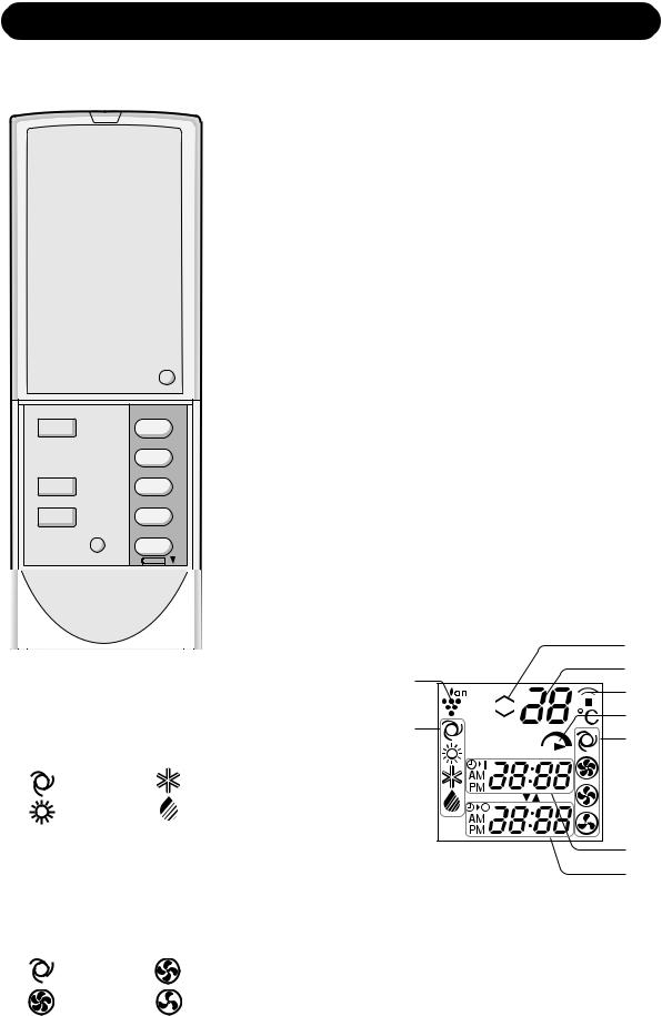
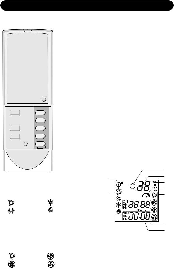
REMOTE CONTROL
MODE |
1h |
FAN |
|
SWING |
|
|
SET/C |
11 TRANSMITTER
2 DISPLAY (Liquid Crystal Display)
3 PLASMACLUSTER Button
4 ON/OFF Button
25 THERMOSTAT Button
6 FULL POWER Button
7 MODE Button
38 ONE-HOUR OFF TIMER Button
49 TIMER ON Button (for setting the timer)
50 TIMER OFF Button (for setting the timer)
6q TIME ADVANCE Button
7 |
w TIME REVERSE Button |
|
8 |
||
|
9e FAN Button
0r TIMER SET/CANCEL Button
q |
t Indicates BATTERY COMPARTMENT is |
|
below this mark |
||
w |
y CLOCK Button |
|
e |
||
|
ru SWING Button
t y
|
u |
|
|
|
|
|
|
|
|
p |
|
|
|
|
i |
a |
|
L.C.D. REMOTE CONTROL DISPLAY |
s |
||||
|
|||||
i PLASMACLUSTER SYMBOL |
|
o |
d |
||
|
f |
||||
o MODE SYMBOLS |
|
|
|
|
|
: AUTO |
: COOL |
|
|
|
|
: HEAT |
: DRY |
|
|
|
|
p THERMOSTAT SETTING FOR AUTO AND |
|
|
g |
||
DRY MODES |
|
|
|
||
|
|
|
|
||
a TEMPERATURE INDICATOR |
|
|
h |
||
s TRANSMITTING SYMBOL |
g TIMER ON INDICATOR/CLOCK |
|
|||
d FULL POWER SYMBOL |
|
|
Indicates the on timer preset time or current |
||
f FAN SPEED SYMBOLS |
|
|
time. |
|
|
|
h TIMER OFF INDICATOR |
|
|||
|
|
|
|||
: AUTO |
: LOW |
Indicates the preset time for off timer or one- |
: HIGH |
: SOFT |
hour off timer. |
|
E-4
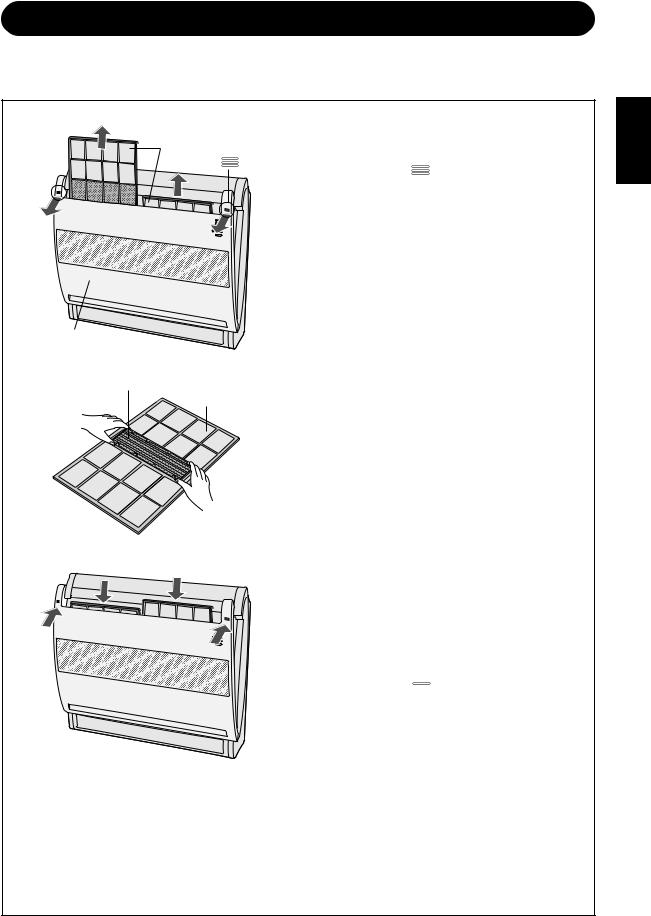
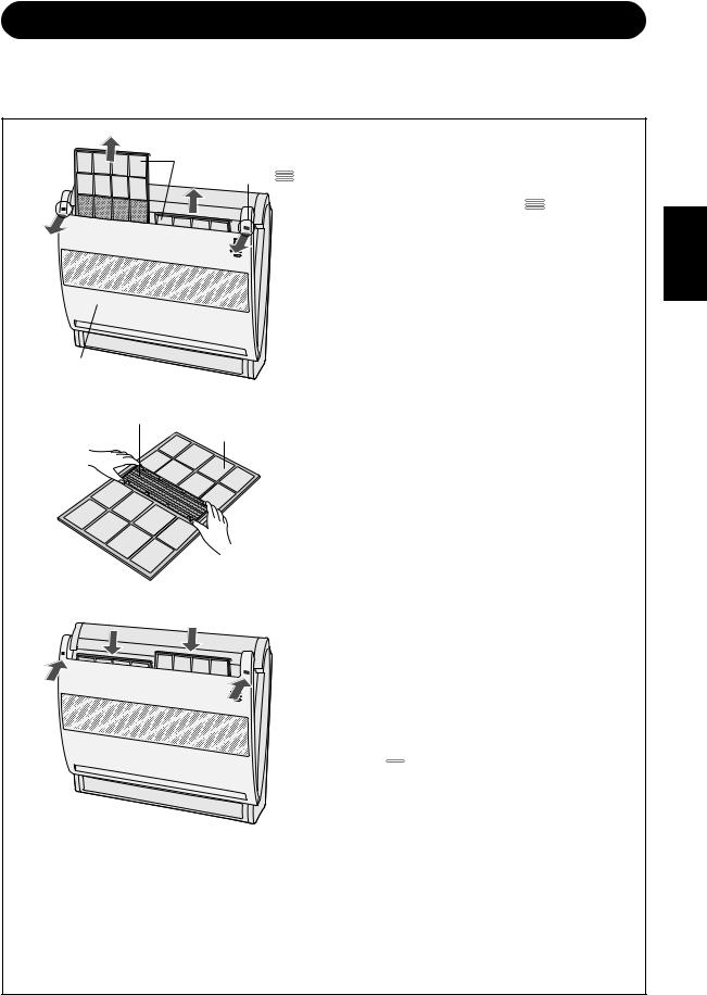
SETTING DEODORANT FILTERS
The deodorant filters are packed as accessory of this unit. During operation of the air conditioner, the filters absorb odor elements from the air.
air filter |
mark |
1 |
Open the front grille. |
|
|
Hold the two " |
" marked corners on |
||
|
|
|||
|
|
|
the front grille and pull it toward yourself |
|
|
|
|
to open. |
|
|
|
2 |
Take out the air filters. |
|
front grille
deodorant filter
air filter
3 Set the deodorant filters under the filter stoppers located on the air filters.
4 Reinstallsitions. the air filters in the original po-
5 Close the front grille.
Press the two "  "marked positions on the front grille to lock it in place.
Precautions
•The deodorant filters are sealed in a plastic bag to keep their deodorant effect.
Do not open the bag until using the filters. (Otherwise the filters life may get shorter.)
•Do not expose the filters to direct sunlight. (Otherwise they may deteriorate.)
ENGLISH
E-5
USING THE REMOTE CONTROL
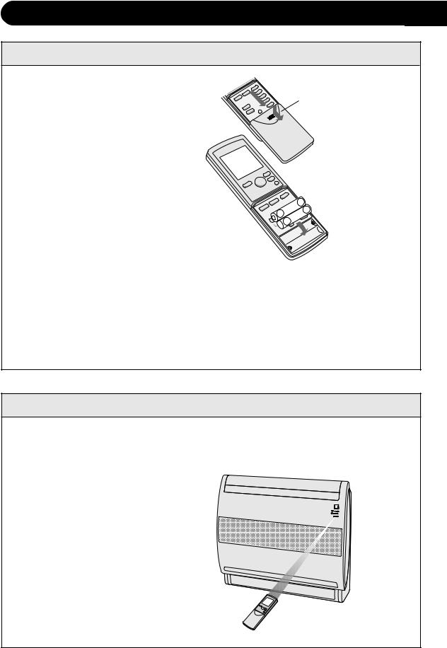
LOADING BATTERIES Use two size-AAA (R03) batteries.
1 Removecover. the remote control
2 Insert batteries in the compartment, making sure the ± and
— polarities are correctly aligned.
•The display indicates “AM 6:00” when batteries are properly installed.
3 Reinstall the cover.
Remote control cover
 -
-
+  +
+
 -
-
NOTES:
•The battery life is approximately one year in normal use.
•When you replace the batteries, always change both batteries, and make sure they are the same type.
•If the remote control does not operate properly after replacing the batteries, take out the batteries and reinstall them again after 30 seconds.
•If you will not be using the unit for a long time, remove the batteries from the remote control.
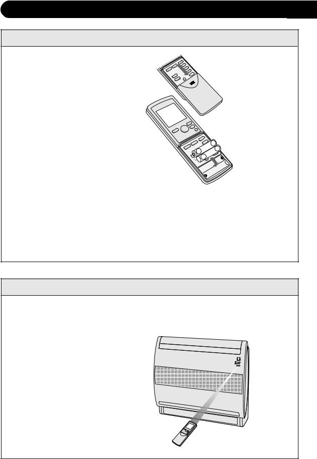
HOW TO USE THE REMOTE CONTROL
Point the remote control towards the unit’s signal receiver window and press the desired button. The unit generates a beep when it receives the signal.
•Make sure there is no curtain or other object between the remote control and the
unit.
• The remote control can send signals from up to 7 metres away.
E-6
 CAUTION
• Do not allow the signal receiver window to receive strong direct sunlight, since it can |
ENGLISH |
• Using a fluorescent lamp with a quick starter in the same room may interfere with |
|
adversely affect its operation. If the signal receiver window is exposed to direct sunlight, |
|
close a curtain to block the light. |
|
transmission of the signal. |
|
• The unit can be affected by signals transmitted from the remote control of a television, |
|
VCR or other equipment used in the same room. |
|
• Do not leave the remote control in direct sunlight or near a heater. Also, protect the unit |
|
and remote control from moisture and shock which can discolour or damage them. |
|
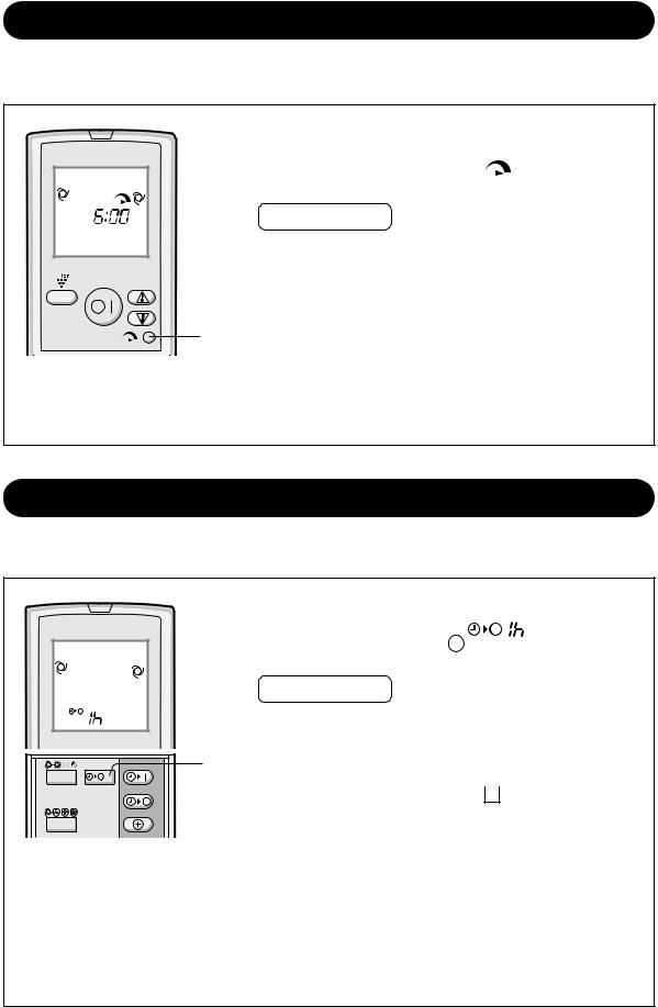
SET CURRENT CLOCK TIME
There are two clock modes: 12-hour mode and 24-hour mode.
Example: 5 o’clock in the afternoon
Clock |
Display |
|
12-hour mode |
PM 5:00 |
|
24-hour mode |
17:00 |
|
MODE |
1h |
|
|
1 |
To set to the 12-hour mode, press the |
|
|
|
|
||
|
|
|
|
|
CLOCK button once in the first step. |
|
|
|
|
|
To set to the 24-hour mode, press the |
FAN |
|
|
2 |
|
CLOCK button twice in the first step. |
SWING |
|
|
|
Press the TIME ADVANCE or REVERSE |
|
|
|
|
3 |
2 button to set the current time. |
|
|
|
SET/C |
|
• Keep the button pressed to advance |
|
|
|
|
|
||
|
|
|
|
|
or reverse the time display quickly. |
13 Press the SET/C button.
•The colon (:) blinks to indicate that the clock is functioning.
NOTE:
•The current time cannot be set when the timer is operating.
E-7
BASIC OPERATION
1 Press the MODE button to select the operation mode.
AUTO HEAT COOL DRY
|
|
2 tion.Press the ON/OFF button to start opera- |
|||
|
|
• The red OPERATION lamp ( |
) on the unit |
||
|
2 |
will light. |
|
|
|
|
|
|
|
||
|
5 |
Press the THERMOSTAT button to set the |
|||
|
3 desired temperature. |
(Example: 1°C higher) |
|||
|
3 |
• In the AUTO and DRY |
|
|
|
|
modes, the tempera- |
|
C |
||
|
1 |
ture can be changed |
|
||
|
in 1°C increments |
|
|
||
|
within the range of 2°C |
(Example: 2°C lower) |
|||
|
|
||||
MODE |
1h |
higher to 2°C lower |
|||
|
|
||||
|
|
from the temperature |
|
|
|
|
4 |
automatically deter- |
|
C |
|
FAN |
mined by the air con- |
|
|||
|
|
ditioner. |
|
|
|
SWING |
|
• In the COOL and HEAT modes, the tempera- |
|||
|
SET/C |
ture can be set within the range of 18 to 32°C |
|||
4 Press the FAN button to set the desired fan
speed. AUTO SOFT LOW HIGH
•In the DRY mode, the fan speed is preset to AUTO and cannot be changed.
5 To turn off the unit, press the ON/OFF button again.
•The red OPERATION lamp (  ) on the unit will turn off.
When using your air-conditioner with multi-system
(GS-XPM9FGR,GS-XPM12FGR,GS-XPM18FGR)
With a multi system air conditioner, multiple indoor units can be connected to one outdoor unit. When the setting mode differs among indoor unit(s), the indoor unit(s) operated later may not work.
•When the indoor unit(s) is/are operating in HEAT mode, the remaining unit(s) can not operate in COOL or DRY mode.
•When the indoor unit(s) is/are operating in COOL or DRY mode, the remaining unit(s) can not operate in HEAT mode.
When the mode of the indoor unit(s) later operated is/are different from those which is /are in operation, after a few seconds, a long BEEP will be emitted and the OPERATION lamp and TIMER lamp will blink alternately. This shows that the later operated unit(s) is/are not working. In such case, change the mode to the same mode which the other indoor unit(s) is/are operating in.
E-8
TIPS ABOUT AUTO MODE
(GS-XP9FGR,GS-XP12FGR,GS-XP18FGR)
In the AUTO mode, the temperature setting and mode are automatically selected according to the room temperature and outdoor temperature when the unit is turned on.
Modes and Temperature Settings
|
|
|
|
|
|
|
||||||
|
|
|
||||||||||
|
|
|
|
|
|
|
|
|
|
|
|
|
|
|
|
|
|
|
|
|
|
|
|
||
|
|
|
|
|
|
|
|
|
|
|
|
|
|
|
|
|
|
|
|
|
|
|
|||
|
|
|
|
|
|
|
|
|
|
|
|
|
|
|
|
|
|
|
|
|
|
|
|
|
|
|
|
|
|
|
|
|
|
|
|
|
|
|
|
|
|
|
|
|
|
|
|
|
|
|
|
|
|
|
|
|
|
|
|
|
|
|
||
|
|
|
|
|
|
|
|
|
|
|
|
|
the figures in ( ) are temperature settings
•During operation, if the outdoor temperature changes, the temperature settings will automatically slide as shown in the chart.
•During seasons when you need COOLING at daytime and HEATING at night, or if the room temperature should become extremely higher than the temperature setting, due to supplementary heating equipment, the mode will automatically switch between HEAT and COOL mode to keep the comfortable room temperature. (MODE
CHANGEOVER)
TIPS ABOUT AUTO MODE
(GS-XPM9FGR,GS-XPM12FGR,GS-XPM18FGR)
In the AUTO mode, the temperature setting and mode are automatically selected according to the room temperature and outdoor temperature when the unit is turned on.
Modes and Temperature Settings
|
|
|
|
|
|
|
|
|
|
||||||
|
|
|
|
|
|
||||||||||
|
|
|
|
|
|
|
|
|
|
|
|
|
|
|
|
|
|
|
|
|
|
|
|
|
|
|
|
|
|
||
|
|
|
|
|
|
|
|
|
|
|
|
|
|
|
|
|
|
|
|
|
|
|
|
|
|
|
|||||
|
|
|
|
|
|
|
|
|
|
|
|
|
|
|
|
|
|
|
|
|
|
|
|
|
|
|
|
|
|
|
|
|
|
|
|
|
|
|
|
|
|
|
|
|
|
||
the figures in ( ) are temperature settings
•During operation, if the outdoor temperature changes, the temperature settings will automatically slide as shown in the chart.
•Mode of the unit operated first will have priority over unit(s) without reference to the chart.
ENGLISH
E-9
ADJUSTING THE AIR FLOW DIRECTION
VERTICAL AIR FLOW DIRECTION |
|||
MODE |
1h |
1 |
Press the SWING button. |
|
|
|
• The vertical adjustment louvre for upper outlet |
|
1 |
|
will change its angle continuously. |
FAN |
2 Press the SWING button again when the |
||
SWING |
2 |
|
vertical adjustment louvre for upper outlet |
|
is at the desired position. |
||
|
|
||
|
SET/C |
|
• The louvre will stop moving within the range |
|
|
|
|
|
|
|
shown in the diagram. |
|
|
|
• The adjusted position will be memorized and will |
|
|
|
be automatically set to the same position when |
|
|
|
operated the next time. |
NOTE:
The vertical adjustment louvre for lower outlet is automatically set and cannot be changed.
HORIZONTAL AIR FLOW DIRECTION
Hold the horizontal adjustment louvre levers as shown in the diagram and adjust the air flow direction.
Louvre levers
 CAUTION
Never attempt to adjust the vertical adjustment louvres manually.
•Manual adjustment of the vertical adjustment louvre can cause the unit to malfunction when the remote control is used for adjustment.
•When the vertical adjustment louvre is positioned at the lowest position in the COOL or DRY mode for an extended period of time, condensation may result.
Do not adjust the horizontal adjustment louvre to the extreme left or right in the COOL mode with the fan speed set to “SOFT(  )” for an extended period of time.
Condensation may form on the louvres.
E-10
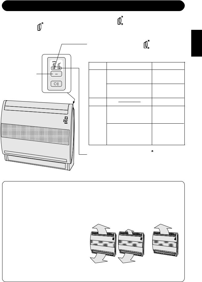
AIR OUTLET SELECTION
Press AIR OUTLET SELECTION button, and choose " |
(Upper and lower automatic |
air outlets)" or " (Upper air outlet)". |
|
|
When setting air outlet to |
". |
|
|
Air is blown out automatically from the upper and |
||
|
lower air outlet as shown below. |
||
|
MODE |
CONDITION |
AIR OUTLET |
AIR OUTLET |
|
When room temperature |
Upper and lower |
SELECTION |
|
is higher than temperature |
air outlet. |
|
setting. |
|
|
button |
COOL |
|
|
|
|
||
|
When room temperature |
|
|
|
|
|
|
|
|
is close to temperature |
Upper air outlet |
|
|
setting. |
|
|
DRY |
|
Upper air outlet |
|
|
When outlet air |
|
|
|
temperature is low. |
Upper air outlet |
|
|
(operation start up, de- |
|
|
HEAT |
icing) |
|
|
When outlet air |
Upper and lower |
|
|
|
||
|
|
temperature is high. |
air outlet. (Lower |
|
|
|
air flow is greater |
|
|
|
than upper air |
|
|
|
flow) |
When setting air outlet to "  ".
".
Air is blown out from the upper air outlet, regardless to the mode and condition.
TIPS ABOUT UPPER AND LOWER AUTOMATIC AIR OUTLET
Air outlet is automatically selected according to room temperature and outlet air temperature, to keep comfortable room condition.
During cooling operation
When room temperature is higher than temperature setting, air is blown out from upper and lower air outlet to make the room cool rapidly. When room temperature is close to temperature setting, air is blown out from upper air outlet to avoid feeling the cold air flow.
During heating operation
When outlet air temperature is low, air is blown out from upper air outlet to prevent cold air blowing to the floor. When outlet air temperature becomes high, air is blown out from both air outlet with main air flow from lower outlet to deliver warm air to the floor.
Upper and lower air outlet Upper air outlet
COOL mode HEAT mode
ENGLISH
E-11
FULL POWER OPERATION
In this operation, the air conditioner works at maximum power to make the room cool or warm so rapidly that you can use it just after you come home.
PM
1 To activate the FULL POWER operation, press the FULL POWER button during operation.
• |
The remote control will display “ |
”. |
• |
The temperature display will go off. |
|
TO CANCEL
Press the FULL POWER button again.
•FULL POWER operation will also be cancelled when the operation mode is changed, or when the unit is
turned off.
1
NOTE:
• You cannot set the temperature or fan speed during the FULL POWER operation.
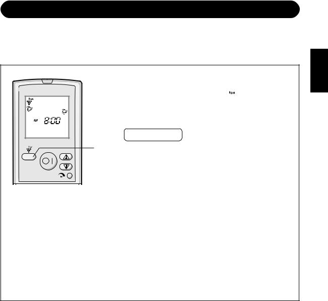
ONE-HOUR OFF TIMER
When the ONE-HOUR OFF TIMER is set, the unit will automatically turn off after one hour.
1 |
Press the ONE-HOUR OFF TIMER button. |
||||
|
• |
The remote control displays “ |
”. |
||
|
• |
The orange TIMER lamp ( |
|
|
) on the unit will light up. |
|
|
|
|||
|
|
||||
|
• |
The unit will stop operating after one hour. |
|||
TO CANCEL
Press the TIMER CANCEL (SET/C) button.
• The orange TIMER lamp (  ) on the unit will turn off.
|
|
1 |
Alternatively, turn the unit off by pressing the ON/ |
MODE |
1h |
OFF button. |
• The red OPERATION lamp (  ) and the orange TIMER lamp (
  ) on the unit will turn off.
FAN
NOTES:
•The ONE-HOUR OFF TIMER operation has priority over TIMER ON and TIMER OFF operations.
•If the ONE-HOUR OFF TIMER is set while the unit is not operating, the unit will operate for an hour at the formerly set condition.
•If you wish to operate the unit for another hour before the ONE-HOUR OFF TIMER is activated, press the ONE-HOUR OFF TIMER button again during operation.
•If TIMER ON and/or TIMER OFF are set, TIMER CANCEL button cancels every setting.
E-12
PLASMACLUSTER OPERATION
The Plasmacluster ion generator inside the air conditioner will release positive and negative Plasmacluster ions into the room.
Approximately the same numbers of positive and negative ions released into the air will reduce some airborne mold.
1 Duringbutton. operation, press the PLASMACLUSTER
• The remote control will display “ 
 ”.
”.
• The blue PLASMACLUSTER lamp on the unit will light up.
|
TO CANCEL |
1 |
Press the PLASMACLUSTER button again. |
|
• The PLASMACLUSTER lamp on the unit will turn off. |
NOTES:
•Use of the PLASMACLUSTER operation will be memorized, and it will be activated the next time you turn on the air conditioner.
To perform the PLASMACLUSTER operation without accompanying heat, cool or dry mode, press the PLASMACLUSTER button while the unit is not operating.
•The mode symbol of the remote control will go off and fan speed can not be set to AUTO.
•With multi-system models (GS-XPM9FGR/GS-XPM12FGR/GS-XPM18FGR), you may feel warm air blown out from the unit when HEATING is performed with unit in other room. In this case, indoor fan will not operate continuously.
ENGLISH
E-13
TIMER OPERATION
NOTE:
Before setting the timer, make sure the clock is properly set with the current time.
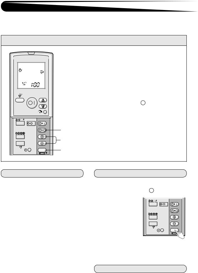
TIMER OFF
1 Press the TIMER OFF (  ) button.
2 The TIMER OFF indicator will blink; press the TIME ADVANCE or REVERSE buttons to set the desired time. (The time can be set in 10minute increments.)
3 Point the remote control at the signal receiver window on the unit and press the TIMER SET (SET/C) button.
• The orange TIMER lamp (  ) on the unit will light.
• The unit will generate a beep when it receives the signal.
MODE |
1h |
1 |
|
|
|
FAN |
|
2 |
SWING |
|
|
|
SET/C |
3 |
|
|
TIPS ABOUT TIMER OFF OPERATION
When the TIMER OFF mode is set, the temperature setting is automatically adjusted to prevent the room from becoming excessively hot or too cold while you sleep. (Auto Sleep function)
COOL/DRY MODE:
•One hour after the timer operation begins, the temperature setting rises 1°C higher than the original temperature setting.
HEAT MODE:
•One hour after the timer operation begins, the temperature setting drops 3°C lower than the original thermostat setting.
TO CANCEL TIMER MODE
Press the TIMER CANCEL (SET/C) button.
•The orange TIMER lamp (  ) on the unit will turn off.
•The current clock 
time will be dis- |
MODE |
1h |
played on the re- |
|
|
mote control. |
|
|
|
FAN |
|
|
SWING |
|
SET/C
NOTE:
•If any TIMER ON, TIMER OFF and ONE-HOUR OFF TIMER are set, the TIMER CANCEL button cancels all settings.
TO CHANGE TIME SETTING
Cancel the TIMER setting first, then set it again.
E-14
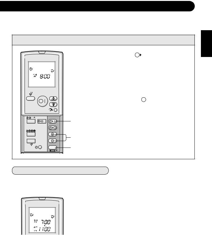
TIMER ON
1 |
Press the TIMER ON ( |
|
|
) button. |
|
|
|||
|
||||
|
|
|||
2 |
The TIMER ON indicator will blink; press the TIME |
|||
ADVANCE or REVERSE buttons to set the de- |
||||
sired time. (The time can be set in 10-minute increments.)
3 Point the remote control at the signal receiver window on the unit and press the TIMER SET (SET/C) button.
• |
The orange TIMER lamp ( |
|
) on the unit will light. |
|
|||
• |
The unit will generate a beep when it receives the |
||
|
signal. |
|
|
MODE |
1h |
|
1 |
4 Select the operation condition. |
|
|
|
|
|
|
|
|
|
NOTE: |
FAN |
|
|
2 |
• The unit will turn on prior to the set timer to allow the |
SWING |
|
|
room to reach the desired temperature by the pro- |
|
|
|
|
3 |
grammed time. (Awaking function) |
|
|
SET/C |
|
|
|
|
|
|
COMBINED USE OF ON AND OFF TIMERS
You can use the ON and OFF timers in combination.
Example:
To stop operation at 11:00 p.m. and resume operation (With the same mode and temperature settings) to turn on the unit by 7:00 a.m.
1 Set the TIMER OFF to 11:00 p.m. during operation.
2 Set the TIMER ON to 7:00 a.m.
The arrow (  or
or  ) between the TIMER ON indicator and the TIMER OFF indicator shows which timer will activate first.
NOTES:
•You cannot programme the ON-TIMER and OFF-TIMER to operate the unit at different temperatures or other settings.
•Either timer can be programmed to activate prior the other.
ENGLISH
E-15
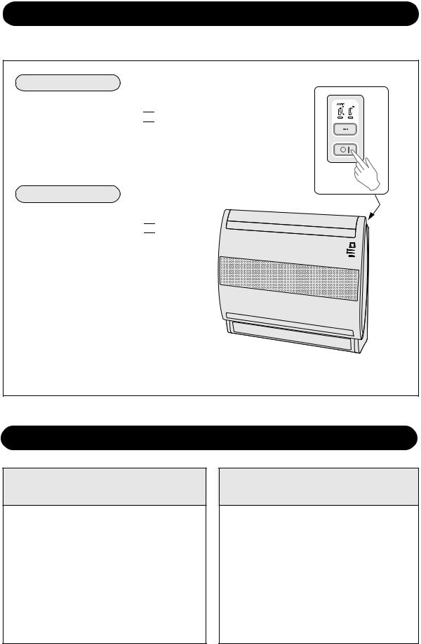
MAIN UNIT OPERATION
Use this operation when the remote control is not available.
TO TURN ON
Press the POWER button on the unit.
•The red OPERATION lamp ( 

 ) on the unit will light and the unit will start operating in the AUTO mode.
•The fan speed and temperature setting are set to AUTO.
TO TURN OFF
Press the POWER button again.
•The red OPERATION lamp ( 

 ) on the unit will turn off.
MAINTENANCE
MAINTENANCE AFTER AIR CONDITIONER SEASON
1 Operate the unit in the COOL mode, temperature setting 32°C, for about half a day to allow the mechanism to thoroughly dry.
2 Stop the operation and unplug the unit. Turn off the circuit breaker, if you have one exclusively for the air conditioner.
3 Cleanthem. the filters, then reinstall
MAINTENANCE BEFORE AIR CONDITIONER SEASON
1 Make sure that the air filters are not dirty.
2 Make sure that nothing obstructs the air inlet or outlet.
3 Check the outdoor mounting rack periodically for wear and to make sure it is firmly in place.
E-16
MAINTENANCE
Be sure to stop the operation and turn off the circuit breaker before performing any maintenance.
CLEANING THE UNIT AND THE REMOTE CONTROL
Wipe them with a soft cloth.
•Do not directly splash or pour water on them. We can cause electrical shock or equipment damage.
•Do not use hot water, thinner, abrasive powders or strong solvents.
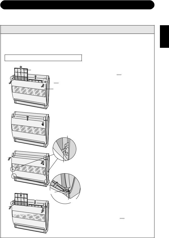
The front grille can also be removed
2
air filter


 mark
mark
1 OPEN THE FRONT GRILLE
Hold the two "  " marked corners on the front grille and pull it toward yourself to open.
1 |
front grille |
3
upper shaft
receiver
2
2 REMOVE THE AIR FILTERS
3 REMOVE THE FRONT GRILLE
Lift the front grille upward as shown in picture.
4 CLEAN THE FRONT GRILLE
Wipe the front grille with a soft cloth. If the front grille is dirty, wash it with warm water and a mild detergent. Dry the front grille completely in the shade before reinstalling.
5
6
7 


upper shaft
1
lower shaft receiver
lower shaft
5 REPLACEGRILLE THE FRONT
1Fit the both lower shafts into the lower shaft receivers.
2Close the front grill and lift it to hook both upper shafts into the upper shaft receivers.
6 REINSTALL THE AIR FILTERS
7 CLOSE THE FRONT GRILLE
Press the two "  " marked positions on the front grille to lock it in place.
ENGLISH
E-17
MAINTENANCE
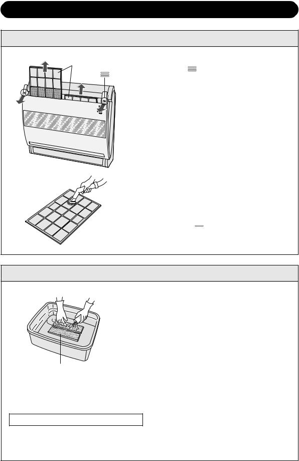
CLEANING THE FILTERS |
The air filters should be cleaned every two weeks. |
|
air filter |
1 |
OPEN THE FRONT GRILLE |
|
mark |
Hold the two " " marked corners on the front |
|
grille and pull it toward yourself to open. |
|
|
2 |
REMOVE THE AIR FILTERS |
|
3 |
TAKE OFF THE DEODORANT FILTERS |
|
|
FROM THE AIR FILTERS |
|
4 |
CLEAN THE AIR FILTERS |
|
|
Use a vacuum cleaner to remove dust. If the |
filters are dirty, wash them with warm water and a mild detergent. Dry filters in the shade before reinstalling.
5 SET THE DEODORANT FILTERS
6 REINSTALL THE AIR FILTERS
7 CLOSE THE FRONT GRILLE
Press the two "  " marked positions on the front grille to lock it in place.
The deodorant filters should be
CLEANING THE DEODORANT FILTERS cleaned every two weeks.
1 REMOVE THE AIR FILTERS
2 CLEAN THE DEODORANT FILTERS
1 Take off the deodorant filters from the air filters.
2 Soak the deodorant filters in mild detergent dilution for 10 to 20 minutes. Rinse thoroughly with water, dry completely under sunlight.
3Set the clean deodorant filters, under the filter stoppers located on the air filters.
deodorant filter
3 REINSTALL THE AIR FILTERS
NOTE:
•Replacement is necessary at the interval of 3 years, as the deodorising effect will deteriorate. The new filters are available at your nearest dealer.
Replacement filter: Type AZ-F900G
Disposal of Filters
Please dispose of replaced filters according to the local disposal laws and regulations.
Deodorant filter material: (Polyester)
E-18
ADDITIONAL NOTES ON OPERATION
OPERATING TEMPERATURE RANGE
|
|
INDOOR TEMP. |
|
OUTDOOR TEMP. |
|
|
|
upper limit |
32°C |
46°C |
(GS-XP9FGR,GS-XP12FGR,GS-XP18FGR) |
|
ENGLISH |
COOLING |
43°C |
(GS-XPM9FGR,GS-XPM12FGR,GS-XPM18FGR) |
|
|||
|
|
|
||||
|
|
|
|
|||
lower limit |
21°C |
–10°C (GS-XP9FGR,GS-XP12FGR,GS-XP18FGR) |
|
|
||
|
|
|
||||
|
21°C (GS-XPM9FGR,GS-XPM12FGR,GS-XPM18FGR) |
|
|
|||
|
|
|
|
|
||
HEATING |
upper limit |
27°C |
|
24°C |
|
|
|
|
|
|
|
|
|
lower limit |
– |
|
–15°C |
|
|
|
|
|
|
|
|||
|
|
|||||
|
|
|
|
|
|
|
•The built-in protective device may prevent the unit from operating when used out of this range.
•Condensation may form on the air outlet if the unit operates continuously in the COOL or DRY mode when humidity is over 80 percent.
WHEN POWER FAILURE OCCURS
This air conditioner has a memory function to store settings when a power failure occurs.
After power recovery, the unit will automatically re-start in the same settings which were active before the power failure, except for timer settings.
If the timers were set before a power failure, they will need to be re-set after power recovery.
PREHEATING FUNCTION
In the HEAT operation, the indoor fan may not start for two to five minutes after the unit is turned on to prevent cold air from blowing out of the unit.
DE-ICING FUNCTION
•When ice forms on the heat exchanger in the outdoor unit during the HEAT operation, an automatic de-icer provides heat for about 5 to 10 minutes to remove the ice. During de-icing, the inside and outside fans stop operating.
•After de-icing is completed, the unit automatically resumes operation in the HEAT mode.
HEATING EFFICIENCY
•The unit employs a heat pump that draws heat from the outside air and releases it into the room. The outside air temperature therefore greatly affects the heating efficiency.
•If the heating efficiency is reduced due to low outside temperatures, use an additional heater.
•It takes time to warm up and heat the entire room because of the forced air circulation system.
TIPS ON SAVING ENERGY
Below are some simple ways to save energy when you use your air conditioner.
SET THE CORRECT TEMPERATURE
•Setting the thermostat 1°C higher than the desired temperature in the COOL mode and 2°C lower in the HEAT mode will save approximately 10 percent in power consumption.
•Setting the temperature lower than necessary during cooling operation will result in increased power consumption.
BLOCK DIRECT SUNLIGHT AND PREVENT DRAFTS
•Blocking direct sunlight during cooling operation will reduce power consumption.
•Close the windows and doors during cooling and heating operations.
SET PROPER AIR FLOW DIRECTION TO OBTAIN THE BEST AIR CIRCULATION
KEEP FILTER CLEAN TO ENSURE THE MOST EFFICIENT OPERATION MAKE MOST OF THE TIMER OFF FUNCTION
DISCONNECT THE POWER CORD WHEN THE UNIT IS NOT USED FOR AN EXTENDED PERIOD OF TIME
• The indoor unit still consumes a small amount of power when it is not operating.
E-19

BEFORE CALLING FOR SERVICE
The following conditions do not denote equipment malfunctions
UNIT DOES NOT OPERATE |
SWISHING NOISE |
|||
The unit will not operate if it is turned on immediately |
The soft, swishing noise is the sound of the refrig- |
|||
after it is turned off. The unit will not operate |
erant flowing inside the unit. |
|||
immediately after the mode is changed. This is to |
|
|
||
protect the internal mechanisms. Wait 3 minutes |
|
|
||
|
|
|||
before operating the unit. |
WATER VAPOUR |
|||
|
|
• |
In the COOL and DRY operation, water vapour |
|
|
|
|||
UNIT DOES NOT SEND OUT WARM AIR |
|
can sometimes be seen at the air outlet due to |
||
The unit is preheating or de-icing. |
|
the difference between the room air tempera- |
||
|
ture and the air discharged by the unit. |
|||
|
|
• |
In the HEAT operation, water vapour may flow |
|
|
|
|
out of the outdoor unit during de-icing. |
|
ODORS |
|
|||
|
|
|||
|
|
|||
Carpet and furniture odors that entered into the |
THE OUTDOOR UNIT DOES NOT |
|||
unit and the air conditioner's inner component |
STOP |
|||
odors at the early stage of installation may be sent |
||||
out from the unit. |
After stopping the operation, the outdoor unit will |
|||
|
|
rotate its fan for about a minute to cool down the |
||
CRACKING NOISE |
unit. |
|||
|
|
|||
The unit may produce a cracking noise. This sound |
ODOR EMITTED FROM THE |
|||
is generated by the friction of the front panel and |
||||
other components expanding or connecting due to a |
PLASMACLUSTER AIR OUTLET |
|||
temperature change. |
This is the smell of ozone generated from the |
|||
|
|
Plasmacluster ion generator. The ozone concen- |
||
A LOW BUZZING NOISE EMITTED |
tration is very small, posing no adverse effect on |
|||
your health. The ozone discharged into the air |
||||
This is a sound emitted when the unit is generating |
rapidly decomposes, and its density in the room |
|||
will not increase. |
||||
Plasmacluster ions. |
||||
|
|
|||
|
|
|
||
(Only for models GS-XPM9FGR/GS-XPM12FGR/GS-XPM18FGR) |
||||
|
|
|||
INDOOR UNIT BECOMES WARM |
UNIT DOES NOT OPERATE IN YOUR |
|||
EVEN WHEN IDLE |
REQUESTED MODE |
|||
This is because the refrigerant also floes through |
• |
When one indoor unit is operating in COOL or |
||
the idle indoor unit's pipes when the other unit is |
|
DRY mode, you can not operate the other unit |
||
operated in HEAT mode. |
|
in HEAT mode. (After a few seconds, a long |
||
|
|
|
BEEP will be emitted, and the OPERATION |
|
|
|
|
lamp and TIMER lamp will blink alternately.) |
|
|
|
|
||
INDOOR UNIT BECOMES WARM |
• When one indoor unit is operating in HEAT |
|||
|
mode, you can not operate the other unit in |
|||
EVEN WHEN NOT DURING HEATING |
|
COOL nor DRY mode. (After a few seconds, a |
||
OPERATION |
|
long BEEP will be emitted, and the OPERA- |
||
When the PLASMACLUSTER button is pressed |
|
TION lamp and TIMER lamp will blink alter- |
||
|
nately.) |
|||
while the unit is not operating, the without accom- |
|
|
||
panying air conditioning mode (er. HEATING or |
|
|
|
|
|
|
|
||
COOLING). At this time, you may feel warm air |
UNIT DOES NOT SEND OUT AIR |
|||
coming out from the unit air outlet if HEATING is |
||||
performed with units in other rooms. Indoor fan will |
(PLASMACLUSTER operation with- |
|||
decrease its rotating speed and will turn ON and |
out accompanying air conditioning |
|||
OFF depending on the room temperature. |
mode) |
|||
|
|
|||
|
|
The other unit(s) is/are de-icing. |
||
|
|
|
|
|
E-20
If the unit appears to be malfunctioning, check the following points before calling for service.
IF THE UNIT FAILS TO OPERATE
Check to see if the circuit breaker has tripped or the fuse has blown.
IF THE UNIT FAILS TO COOL (OR HEAT) THE ROOM EFFECTIVELY
Check the filters. If dirty, clean |
Check the outdoor unit to make |
Check the thermostat is proper |
them. |
sure nothing is blocking the air in- |
setting. |
|
let or outlet. |
|
|
|
|
Make sure windows and doors |
A large number of people in the |
Check whether any heat-gen- |
are closed tightly. |
room can prevent the unit from |
erating appliances are operat- |
|
achieving the desired tempera- |
ing in the room. |
|
ture. |
|
|
|
|
IF THE UNIT FAILS TO RECEIVE THE REMOTE CONTROL SIGNAL
Check whether the remote con- |
Try to send the signal again with |
Check whether the remote con- |
trol batteries have become old |
the remote control pointed prop- |
trol batteries are installed with |
and weak. |
erly towards the unit’s signal re- |
the polarities properly aligned. |
|
ceiver window. |
|
|
|
|
Please call for service when OPERATION Lamp and TIMER Lamp on the unit blink.
ENGLISH
E-21
Atención: su producto está marcado con este símbolo. Significa que los productos eléctricos y electrónicos usados no deberían mezclarse con los residuos domésticos generales. Existe un sistema de recogida independiente para estos productos.
A. Información sobre eliminación para usuarios particulares
1. En la Unión Europea
Atención: si quiere desechar este equipo, ¡por favor no utilice el cubo de la basura habitual!
Los equipos eléctricos y electrónicos usados deberían tratarse por separado de acuerdo con la legislación que requiere un tratamiento, una recuperación y un reciclaje adecuados de los equipos eléctricos y electrónicos usados.
Tras la puesta en práctica por parte de los estados miembros, los hogares de particulares dentro de los estados de la Unión Europea pueden devolver sus equipos eléctricos y electrónicos a los centros de recogida designados sin coste alguno *.
En algunos países* es posible que también su vendedor local se lleve su viejo producto sin coste alguno si Ud. compra uno nuevo similar.
*) Por favor, póngase en contacto con su autoridad local para obtener más detalles.
Si sus equipos eléctricos o electrónicos usados tienen pilas o acumuladores, por favor deséchelos por separado con antelación según los requisitos locales.
Al desechar este producto correctamente, ayudará a asegurar que los residuos reciban el tratamiento, la recuperación y el reciclaje necesarios, previniendo de esta forma posibles efectos negativos en el medio ambiente y la salud humana que de otra forma podrían producirse debido a una manipulación de residuos inapropiada.
2. En otros países fuera de la Unión Europea
Si desea desechar este producto, por favor póngase en contacto con las autoridades locales y pregunte por el método de eliminación correcto.
Para Suiza: Los equipos eléctricos o electrónicos pueden devolverse al vendedor sin coste alguno, incluso si no compra ningún nuevo producto. Se puede encontrar una lista de otros centros de recogida en la página principal de www.swico.ch o www.sens.ch.
B. Información sobre Eliminación para empresas usuarias
1. En la Unión Europea
Si el producto se utiliza en una empresa y quiere desecharlo:
Por favor póngase en contacto con su distribuidor SHARP, quien le informará sobre la recogida del producto. Puede ser que le cobren los costes de recogida y reciclaje. Puede ser que los productos de tamaño pequeño (y las cantidades pequeñas) sean recogidos por sus centros de recogida locales.
Para España: por favor, póngase en contacto con el sistema de recogida establecido o con las autoridades locales para la recogida de los productos usados.
2. En otros países fuera de la Unión Europea
Si desea desechar este producto, por favor póngase en contacto con sus autoridades locales y pregunte por el método de eliminación correcto.
ES

ESPAÑOL
Gracias por la compra de este acondicionador de aire SHARP. Antes de usar el producto lea el manual detenidamente.
ÍNDICE
• INSTRUCCIONES IMPORTANTES |
|
DE SEGURIDAD ........................................ |
S-1 |
• DESIGNACIÓN DE LAS PIEZAS .............. |
S-3 |
• CONFIGURACIÓN DE LOS FILTROS |
|
DESODORANTES ..................................... |
S-5 |
• USO DEL MANDO A DISTANCIA ............. |
S-6 |
• FUNCIONAMIENTO BÁSICO .................... |
S-8 |
• REGLAJE DE LA DIRECCIÓN DE |
|
LA CORRIENTE DE AIRE ......................... |
S-10 |
• SELECCIÓN DE LA SALIDA DE AIRE ...... |
S-11 |
• FUNCIONAMIENTO A CAPACIDAD |
|
MÁXIMA ..................................................... |
S-12 |
• FUNCIÓN DE DESACTIVACIÓN POR |
|
TEMPORIZADOR DE UNA HORA ............ |
S-12 |
• FUNCIONAMIENTO DEL |
|
PLASMACLUSTER .................................... |
S-13 |
• FUNCIONAMIENTO CON |
|
EL TEMPORIZADOR ................................. |
S-14 |
• FUNCIONAMIENTO DE LA UNIDAD |
|
PRINCIPAL ................................................ |
S-16 |
• MANTENIMIENTO ..................................... |
S-16 |
• OBSERVACIONES ADICIONALES |
|
SOBRE EL FUNCIONAMIENTO ............... |
S-19 |
• ALGUNOS CONSEJOS PARA |
|
AHORRAR ENERGÍA ................................ |
S-19 |
• ANTES DE LLAMAR AL DEPARTAMENTO |
|
DE SERVICIO TÉCNICO ........................... |
S-20 |
INSTRUCCIONES IMPORTANTES DE SEGURIDAD
ADVERTENCIAS PARA EL USO
1 |
No deforme o tire del cable de alimentación. Estirar y mal utilizar el cable de alimentación |
puede ocasionar daños o descargas eléctricas. |
|
2 |
Tenga cuidado de no exponer su cuerpo directamente a la salida de aire durante un largo |
tiempo. Esto puede afectar sus condiciones físicas. |
|
3 |
Al usar el acondicionador de aire para recién nacidos, niños, ancianos, personas |
postradas en cama o inválidas, asegúrese de que la temperatura de la habitación sea |
|
|
la adecuada para ellos. |
4 |
Nunca inserte objetos dentro de la unidad. El insertar objetos puede causar heridas |
debido a la rotación a alta velocidad de los ventiladores internos. |
|
5 |
Conecte a tierra el acondicionador de aire sin falta. No conecte el cableado a tierra con |
la tubería de gas, tubería de agua, barra pararrayos o cable a tierra del teléfono. Una |
|
|
conexión incompleta a tierra puede causar descargas eléctricas. |
6 |
Si sucede algo anormal con el acondicionador de aire (por ej. se detecta un olor a |
quemado), detenga inmediatamente la operación y desactive el cortacircuitos. |
|
7 |
El aparato se debe instalar de acuerdo con las regulaciones nacionales de cableado. La |
inapropiada conexión del cable puede ocasionar un sobrecalentamiento del cable de |
|
|
suministro de alimentación, del enchufe y del tomacorriente, y causar un incendio. |
8 |
Si el cable de alimentación está dañado, éste deberá ser reemplazado por el fabricante, |
por un técnico de servicio autorizado o por una persona similarmente cualificada, para |
evitar situaciones peligrosas. Utilice para reemplazo solo el cable de alimentación especificado por el fabricante.
ADVERTENCIAS PARA LA INSTALACIÓN/DESMONTAJE/REPARACIÓN
•No trate de instalar/desmontar/reparar la unidad por su propia cuenta. La elaboración de un trabajo incorrecto ocasionará descargas eléctricas, fugas de agua, incendios, etc. Consulte a su distribuidor o a personal de servicio cualificado para que realice la instalación/ desinstalación/reparación de la unidad.
ESPAÑOL
S-1

INSTRUCCIONES IMPORTANTES DE SEGURIDAD
PRECAUCIONES PARA EL USO
1 Abrir periódicamente una ventana o una puerta para ventilar la habitación, sobre todo si se usan aparatos que funcionan con gas. Una ventilación insuficiente puede causar escasez de oxigeno.
2 No opere los botones con las manos mojadas. Esto puede causar descargas eléctricas.
3 Por seguridad, desconece el cortacircuito cuando no esté utilizando la unidad por un período de tiempo prolongado.
4
5
6
7
8
9
10
11
PRECAUCIONES PARA UBICACIÓN/INSTALACIÓN
•Asegúrese de conectar el acondicionador de aire a la fuente de alimentación de la tensión y la frecuencia correcta.
La utilización de una fuente de alimentación con un voltaje y frecuencias inadecuados puede ocasionar daños en el equipo e incluso causar un incendio.
•No instale el aparato en lugares donde puede haber fuga de gases. Esto puede causar incendios.
Instale el aparato en un lugar con poco polvo, vapores y humedad.
•Coloque la manguera de drenaje de tal forma que se asegure un drenaje fluido. Un drenaje insuficiente puede causar humedecimiento de la habitación, muebles etc.
•Asegúrese de que se ha instalado un interruptor automático de perdidas o un diferencial, dependiendo de la ubicación de la instalación, para evitar descargas eléctricas.
S-2
DESIGNACIÓN DE LAS PIEZAS
UNIDAD INTERIOR
1 |
1 Lámpara de SELECCIÓN DE |
2 |
SALIDA DE AIRE (verde) |
|
|
3 |
2 Tecla de SELECCIÓN DE |
SALIDA DE AIRE |
3 Tecla de ALIMENTACIÓN
4
4 Filtros de aire
5
6 5 Salida de aire superior
7
6 Deflectores de ajuste horizontal
|
7 Deflectores de ajuste |
|
|
8 |
vertical |
|
|
9 |
8 Lámpara de |
|
|
|
|
|
|
0 |
PLASMACLUSTER (azul) |
|
|
|
|
|
|
q |
9 Lámpara de |
|
|
|
|
|
|
w |
FUNCIONAMIENTO (roja |
) |
|
|
|
|
|
e |
0 Lámpara de TEMPORIZADOR |
||
|
|||
r |
(anaranjada |
) |
|
|
|
|
|
w |
q Ventava RECEPTORA |
|
|
7 |
w Entrada de aire |
6 e Filtros desodorantes
y
r Rejilla delantera
t
t Mando a distancia
y Salida de aire inferior
NOTA: Los aparatos pueden diferir ligeramente de los indicados en las ilustraciones.
ESPAÑOL
S-3
DESIGNACIÓN DE LAS PIEZAS
MANDO A DISTANCIA
11TRANSMISOR
2PANTALLA (de cristal líquido)
3Tecla PLASMACLUSTER
4Tecla de CONEXIÓN/DESCONEXIÓN
2 5Tecla del TERMOSTATO
6Tecla de CAPACIDAD MÁXIMA
7Tecla MODO (MODE)
38Tecla TEMPORIZADOR EN UNA HORA
4 9Tecla de ACTIVACIÓN POR TEMPORIZADOR
5 |
(para regularlo) |
|
MODE |
1h |
FAN |
|
SWING |
|
|
SET/C |
0Tecla de DESACTIVACIÓN POR
6 TEMPORIZADOR (para regularlo)
7
8qTecla de AVANCE DE HORAS
9wTecla de RETROCESO DE HORAS
0eTecla VENTILACIÓN (FAN)
rTecla de AJUSTE/CANCELACIÓN DEL
qTEMPORIZADOR (SET/C)
w
e tIndica que el COMPARTIMIENTO DE PILAS
está por debajo de esta marca
r
tyTecla de RELOJ
y uTecla de CORRIENTE DE AIRE (SWING) u
|
|
|
p |
|
PANTALLA DE VISUALIZACIÓN L.C.D i |
a |
|||
|
||||
DEL MANDO A DISTANCIA |
|
s |
||
iSÍMBOLO DEL PLASMACLUSTER |
o |
d |
||
f |
||||
oSÍMBOLOS DE MODO |
|
|||
|
|
|||
|
|
|
||
: AUTOMÁTICO |
: ENFRIAR |
|
|
|
: CALENTAR |
: DESHUMECTAR |
|
||
pA JUSTE DEL TERMOSTATO PARA LOS |
|
|
||
MODOS AUTOMÁTICO Y DESHUMECTAR |
|
g |
||
aINDICADOR DE TEMPERATURA |
|
|||
|
h |
|||
sSÍMBOLO DE TRANSMISIÓN |
|
|||
gINDICADOR DE ACTIVACIÓN |
|
|||
dSÍMBOLO DE CAPACIDAD MÁXIMA |
|
|||
POR TEMPORIZADOR/RELOJ |
|
|||
fSÍMBOLOS DE VELOCIDAD DEL |
Indica la hora programada para la conexión del |
|||
VENTILADOR |
|
temporizador, o la hora actual. |
|
|
: AUTOMÁTICA |
: BAJA |
hINDICADOR DE DESACTIVACIÓN |
|
|
POR TEMPORIZADOR |
: ALTA |
: SUAVE |
Indica la hora programada para la desactivación |
|
|
por temporizador, o el reglaje de una hora de éste. |
S-4
CONFIGURACIÓN DE LOS FILTROS DESODORANTES
Los filtros desodorantes se encuentran empacados como un accesorio de esta unidad. Durante el funcionamiento del acondicionador de aire, los filtros absorben los malos olores del aire.
Filtro de aire |
1 |
Abra la rejilla delantera. |
|
Marca |
|
||
|
Para abrir la rejilla, sostenga las dos |
||
|
|
esquinas con la marca “ |
” en dicha |
|
|
rejilla y tire de esta hacia usted. |
|
|
2 |
Saque los filtros de aire. |
|
Rejilla delantera
Filtro desodorante
Filtro de aire
3 Ajuste los filtros desodorantes debajo de los topes de filtro localizados en los filtros de aire.
4 Reinstale los filtros de aire en las posiciones originales.
5 Cierre la rejilla delantera.
Presione las dos posiciones con las marcas “  ” en la rejilla delantera para asegurarla en su sitio.
Precauciones
•Los filtros desodorantes se encuentran sellados en una bolsa de plástico para mantener su efecto desodorante.
No abra la bolsa hasta que vaya a utilizar los filtros. (De lo contrario la vida útil de los filtros podría verse reducida).
•No exponga los filtros directamente a la luz solar. (De lo contrario se podrían deteriorar).
ESPAÑOL
S-5
USO DEL MANDO A DISTANCIA
FORMA DE COLOCAR LAS PILAS Use dos pilas tamaño AAA (R03).
1 Retire la cubierta del mando a distancia.
2 Inserte las pilas en el compartimiento, asegúrese de que las polaridades ± y — están correctamente alineadas.
•Si las pilas están bien colocadas, en el visualizador aparecerá “AM 6:00”.
3 Coloque de nuevo la cubierta en su sitio.
Cubierta del mando 
 a distancia
-
+  +
+
 -
-
NOTAS:
•Las pilas alcanzan para un año de uso normal, aproximadamente.
•Al sustituir las pilas, siempre cambie ambas pilas y asegúrese de que son del mismo tipo.
•Si el mando a distancia no funciona apropiadamente después de sustituir las pilas, retírelas y espere unos 30 segundos e introdúzcalas nuevamente.
•Cuando no vaya a usar el aparato durante largo tiempo, saque las pilas del mando a distancia.
FORMA DE USAR EL MANDO A DISTANCIA
Apunte el mando a distancia hacia la ventana receptora de señal de la unidad y pulse la tecla deseada. Cuando la unidad reciba la señal, producirá un sonido audible.
•Cerciórese de que no haya cortinas u otros objetos entre el mando a distancia y la
unidad.
• El mando a distancia puede enviar señales hasta a 7 metros de distancia.
S-6
Loading...