


AR-5127
SERVICE MANUAL
CODE: 00ZAR5127/A1E
DIGITAL LASER COPIER/
PRINTER
MODEL
CONTENTS
[1] NOTE FOR SERVICING. . . . . . . . . . . . . . . . . . . . . . . . . . . . . . . . . 1-1
[2] SYSTEM CONFIGURATION . . . . . . . . . . . . . . . . . . . . . . . . . . . . . 2-1
[3] SPECIFICATIONS . . . . . . . . . . . . . . . . . . . . . . . . . . . . . . . . . . . . . 3-1
[4] CONSUMABLE PARTS . . . . . . . . . . . . . . . . . . . . . . . . . . . . . . . . . 4-1
[5] UNPACKING AND INSTALLATION . . . . . . . . . . . . . . . . . . . . . . . . 5-1
[6] EXTERNAL VIEW AND INTERNAL STRUCTURE . . . . . . . . . . . . 6-1
[7] ADJUSTMENTS, SETTING . . . . . . . . . . . . . . . . . . . . . . . . . . . . . . 7-1
AR-5127
[8] SIMULATION . . . . . . . . . . . . . . . . . . . . . . . . . . . . . . . . . . . . . . . . . 8-1
[9] TROUBLE CODE LIST. . . . . . . . . . . . . . . . . . . . . . . . . . . . . . . . . . 9-1
[10] DISASSEMBLY, ASSEMBLY AND MAINTENANCE . . . . . . . . . . 10-1
[11] OTHERS. . . . . . . . . . . . . . . . . . . . . . . . . . . . . . . . . . . . . . . . . . . . 11-1
Parts marked with “ ” are important for maintaining the safety of the set. Be sure to replace these parts with
specified ones for maintaining the safety and performance of the set.
This document has been published to be used
SHARP CORPORATION
for after sales service only.
The contents are subject to change without notice.
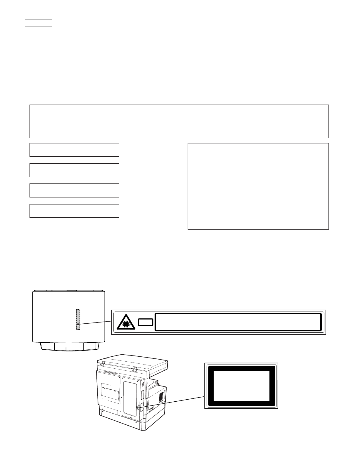
CAUTION
This product is a class 1 laser product that complies with 21CFR 1040.10 and 1040.11 of the CDRH standard and IEC825. This means that this
machine does not produce hazardous laser radiation. The use of controls, adjustments or performance of procedures other than those specified
herein may result in hazardous radiation exposure.
This laser radiation is not a danger to the skin, but when an exact focusing of the laser beam is achieved on the eye’s retina, there is the danger of spot
damage to the retina.
The following cautions must be observed to avoid exposure of the laser beam to your eyes at the time of servicing.
1) When a problem in the laser optical unit has occurred, the whole optical unit must be exchanged as a unit, not as individual parts.
2) Do not look into the machine with the main switch turned on after removing the developer unit, toner cartridge, and drum cartridge.
3) Do not look into the laser beam exposure slit of the laser optical unit with the connector connected when removing and installing the optical
system.
4) The middle frame contains the safety interlock switch.
Do not defeat the safety interlock by inserting wedges or other items into the switch slot.
Warning!
This product is a class A product.
If it is operated in households, offices or similar surroundings, it can produce radio interferences at other
appliances, so that the user has to take adequate countermeasures.
CLASS 1 LASER PRODUCT
LASER KLASSE 1
LUOKAN 1 LASERLAITE
KLASS 1 LASERAPPARAT
INVISIBLE LASER RADIATION,
WHEN OPEN AND INTERLOCKS DEFEATED. AVOID
EXPOSURE TO BEAM.
UNSICHTBARE LASERSTRAHLUNG,
WENN ABDECKUNG GEÖFFNET UND
SICHERHEITSVERRIEGELUNG ÜBERBRÜCKT. NICHT
DEM STRAHL AUSSETZEN.
CAUTION
VORSICHT
LAITTEEN KÄYTTÄMINEN MUULLA KUIN TÄSSÄ
KÄYTTÖOHJEESSA MAINITULLA TAVALLA SAATTAA
ALTISTAA KÄYTTÄJÄN TURVALLISUUSLUOKAN 1
YLITTÄVÄLLE NÄKYMÄTTÖMÄLLE
LASERSÄTEILYLLE.
OM APPARATEN ANVÄNDS PÅ ANNAT SÄTT ÄN I
DENNA BRUKSANVISNING SPECIFICERATS, KAN
ANVÄNDAREN UTSÄTTAS FÖR OSYNLIG
LASERSTRÅLNING, SOM ÖVERSKRIDER GRÄNSEN
FÖR LASERKLASS 1.
AVATTAESSA JA SUOJALUKITUS OHITETTAESSA OLET
ALTTIINA NÄKYMÄTTÖMÄLLE LASERSÄTEILYLLE ÄLÄ
KATSO SÄTEESEEN.
USYNLIG LASERSTRÅLNING VED ÅBNING, NÅR
SIKKERHEDSBRYDERE ER UDE AF
FUNKTION. UNDGÅ UDSAETTELSE FOR
STRÅLNING.
Laserstrahl
VARO !
ADVARSEL
INVISIBLE LASER RADIATION WHEN OPEN AND INTERLOCKS DEFEATED.
CAUTION
AVOID EXPOSURE TO BEAM.
UNSICHTBARE LASERSTRAHLUNG, WENN ABDECKUNG GEÖFFNET UND
VORSICHT
SICHERHEITSVERRIEGELUNG ÜBERBRÜCKT. NICHT DEM STRAHL AUSSETZEN.
USYNLIG LASERSTRÅLNING VED ÅBNING, NÅR SIKKERHEDSBRYDERE ER
ADVARSEL
UDE AF FUNKTION. UNDGÅ UDSAETTELSE FOR STRÅLNING.
VAROITUS!
VARNING
OSYNLIG LASERSTRÅLNING NÄR DENNA DEL ÄR
ÖPPNAD OCH SPÄRREN ÄR URKOPPLAD. BETRAKTA EJ
STRÅLEN. – STRÅLEN ÄR FARLIG.
ADVERSEL
VARNING
AVATTAESSA JA SUOJALUKITUS OHITETTAESSA OLET ALTTIINA NÄKYMÄTTÖMÄLLE
VARO!
LASERSÄTEILYLLE ÄLÄ KATSO SÄTEESEEN.
VARNING !
USYNLIG LASERSTRÅLING NÅR DEKSEL ÅPNES OG SIKKERHEDSLÅS BRYTES.
UNNGÅ EKSPONERING FOR STRÅLEN.
OSYNLIG LASERSTRÅLNING NÄR DENNA DEL ÄR ÖPPNAD OCH SPÄRREN ÄR
URKOPPLAD. BETRAKTA EJ STRÅLEN. – STRÅLEN ÄR FARLIG.
Disconnect the AC cord before servicing the unit.
CLASS 1
LASER PRODUCT
LASER KLASSE 1
LASER WAVE – LENGTH : 795 ± 15 mm
Pulse times : 0.481 ms/6 mm
Out put power : 5 mW

CONTENTS
[1] NOTE FOR SERVICING
1. Warning for servicing . . . . . . . . . . . . . . . . . . . . . . . . . . . . . 1-1
2. Precautions for servicing . . . . . . . . . . . . . . . . . . . . . . . . . . 1-1
3. Note for installing site. . . . . . . . . . . . . . . . . . . . . . . . . . . . . 1-1
[2] SYSTEM CONFIGURATION
1. Structure . . . . . . . . . . . . . . . . . . . . . . . . . . . . . . . . . . . . . . 2-1
A. Hardware . . . . . . . . . . . . . . . . . . . . . . . . . . . . . . . . . . . 2-1
2. System outline (Options) . . . . . . . . . . . . . . . . . . . . . . . . . . 2-2
[3] SPECIFICATIONS
1. Basic specifications . . . . . . . . . . . . . . . . . . . . . . . . . . . . . . 3-1
2. Operation specifications . . . . . . . . . . . . . . . . . . . . . . . . . . . 3-1
A. Common operation. . . . . . . . . . . . . . . . . . . . . . . . . . . . 3-1
B. Copy mode . . . . . . . . . . . . . . . . . . . . . . . . . . . . . . . . . . 3-1
3. Engine specifications . . . . . . . . . . . . . . . . . . . . . . . . . . . . . 3-2
A. Operation and display section . . . . . . . . . . . . . . . . . . . 3-2
B. Paper feed, transport, paper exit section . . . . . . . . . . . 3-2
C. Optical (Image scanning) section . . . . . . . . . . . . . . . . . 3-3
D. Scanner (exposure) section . . . . . . . . . . . . . . . . . . . . . 3-3
E. Image process section . . . . . . . . . . . . . . . . . . . . . . . . . 3-3
F. Fusing. . . . . . . . . . . . . . . . . . . . . . . . . . . . . . . . . . . . . . 3-4
G. Drive . . . . . . . . . . . . . . . . . . . . . . . . . . . . . . . . . . . . . . . 3-4
4. Safety and environmental protection standards. . . . . . . . . 3-4
5. Environment conditions . . . . . . . . . . . . . . . . . . . . . . . . . . . 3-4
[4] CONSUMABLE PARTS
1. List . . . . . . . . . . . . . . . . . . . . . . . . . . . . . . . . . . . . . . . . . . . 4-1
A. LAG . . . . . . . . . . . . . . . . . . . . . . . . . . . . . . . . . . . . . . . 4-1
B. SMEF (Middle East, Africa)/Israel . . . . . . . . . . . . . . . . 4-1
C. Asia affiliates/Asia agent/STCL/SRH/SRS/SRSSC/SBI 4-2
2. Production number identification . . . . . . . . . . . . . . . . . . . . 4-3
3. Environment conditions . . . . . . . . . . . . . . . . . . . . . . . . . . . 4-3
A. Ambient conditions for transporting . . . . . . . . . . . . . . . 4-3
B. Ambient storage conditions (sealed) . . . . . . . . . . . . . . 4-3
C. Operating ambient conditions. . . . . . . . . . . . . . . . . . . . 4-3
4. Life (packed conditions) . . . . . . . . . . . . . . . . . . . . . . . . . . . 4-3
[5] UNPACKING AND INSTALLATION
1. Removal of protective material and fixing screw . . . . . . . . 5-1
2. Removal and storage of fixing pin . . . . . . . . . . . . . . . . . . . 5-1
3. Developer cartridge installation . . . . . . . . . . . . . . . . . . . . . 5-1
4. Toner cartridge installation. . . . . . . . . . . . . . . . . . . . . . . . . 5-2
5. Toner concentration sensor level adjustment. . . . . . . . . . . 5-2
6. Paper size selection for paper feed tray . . . . . . . . . . . . . . 5-2
[6] EXTERNAL VIEW AND INTERNAL STRUCTURE
1. External view. . . . . . . . . . . . . . . . . . . . . . . . . . . . . . . . . . . .6-1
2. Internal . . . . . . . . . . . . . . . . . . . . . . . . . . . . . . . . . . . . . . . .6-1
3. Operation panel . . . . . . . . . . . . . . . . . . . . . . . . . . . . . . . . .6-2
A. Key position . . . . . . . . . . . . . . . . . . . . . . . . . . . . . . . . . .6-2
B. LCD panel . . . . . . . . . . . . . . . . . . . . . . . . . . . . . . . . . . .6-2
4. Motor, Solenoid, Clutch. . . . . . . . . . . . . . . . . . . . . . . . . . . .6-3
5. Sensor. . . . . . . . . . . . . . . . . . . . . . . . . . . . . . . . . . . . . . . . .6-3
6. PWB unit . . . . . . . . . . . . . . . . . . . . . . . . . . . . . . . . . . . . . . .6-4
7. Section . . . . . . . . . . . . . . . . . . . . . . . . . . . . . . . . . . . . . . . .6-4
[7] ADJUSTMENTS, SETTING
1. List of adjustment items . . . . . . . . . . . . . . . . . . . . . . . . . . .7-1
2. Copier adjustment . . . . . . . . . . . . . . . . . . . . . . . . . . . . . . . .7-1
A. Process section . . . . . . . . . . . . . . . . . . . . . . . . . . . . . . .7-1
B. Mechanism section . . . . . . . . . . . . . . . . . . . . . . . . . . . .7-2
C. Image density (exposure) adjustment . . . . . . . . . . . . . .7-9
[8] SIMULATION
1. Operating procedures and operations . . . . . . . . . . . . . . . .8-1
A. Basic operation . . . . . . . . . . . . . . . . . . . . . . . . . . . . . . .8-1
B. Simulation kinds and valid key functions . . . . . . . . . . . .8-1
2. Simulation code list . . . . . . . . . . . . . . . . . . . . . . . . . . . . . . .8-2
3. Details . . . . . . . . . . . . . . . . . . . . . . . . . . . . . . . . . . . . . . . . .8-4
[9] TROUBLE CODE LIST
1. List . . . . . . . . . . . . . . . . . . . . . . . . . . . . . . . . . . . . . . . . . . .9-1
2. Self diagnostics . . . . . . . . . . . . . . . . . . . . . . . . . . . . . . . . . .9-2
[10] DISASSEMBLY, ASSEMBLY AND MAINTENANCE
1. Maintenance table. . . . . . . . . . . . . . . . . . . . . . . . . . . . . . .10-1
2. Counter clear . . . . . . . . . . . . . . . . . . . . . . . . . . . . . . . . . .10-1
3. List of disassembly and assembly . . . . . . . . . . . . . . . . . .10-1
4. Details . . . . . . . . . . . . . . . . . . . . . . . . . . . . . . . . . . . . . . . .10-2
A. Process unit . . . . . . . . . . . . . . . . . . . . . . . . . . . . . . . . .10-2
B. Developing section . . . . . . . . . . . . . . . . . . . . . . . . . . .10-3
C. Fusing section . . . . . . . . . . . . . . . . . . . . . . . . . . . . . . .10-4
D. Paper feed section. . . . . . . . . . . . . . . . . . . . . . . . . . . .10-6
E. Side door unit . . . . . . . . . . . . . . . . . . . . . . . . . . . . . .10-10
F. 1st paper exit unit . . . . . . . . . . . . . . . . . . . . . . . . . . .10-10
G. Laser unit. . . . . . . . . . . . . . . . . . . . . . . . . . . . . . . . . .10-12
H. Power unit . . . . . . . . . . . . . . . . . . . . . . . . . . . . . . . . .10-13
I. PWB . . . . . . . . . . . . . . . . . . . . . . . . . . . . . . . . . . . . .10-13
J. Ozone filter . . . . . . . . . . . . . . . . . . . . . . . . . . . . . . . .10-14
[11] OTHERS
1. Flash ROM version up procedure . . . . . . . . . . . . . . . . . . .11-1
A. Program download procedure
(Main body program) . . . . . . . . . . . . . . . . . . . . . . . . . .11-1
2. User programs . . . . . . . . . . . . . . . . . . . . . . . . . . . . . . . . .11-2

[1] NOTE FOR SERVICING
This Service Manual uses some photographs to assure safe operation.
This Service Manual uses some photographs to assure safe operation.
Please understand the meanings of photographs before servicing.
WARNING: If this WARNING should be ignored, a serious danger
to life or a serious injury would be resulted.
CAUTION: If this CAUTION should be ignored, an injury or a
1. Warning for servicing
1) Be sure to connect the power cord only to a power outlet that
meets the specified voltage and current requirements.
Avoid complex wiring, which may lead to a fire or an electric shock.
It may cause a fire or an electric shock.
2) If there is any abnormality such as a smoke or an abnormal smell,
interrupt the job and disconnect the power plug.
It may cause a fire or an electric shock.
3) Be sure to connect the grounding wire. If an electric leakage
occurs without grounding, a fire or an electric shock may be the
result.
To protect the machine and the power unit from lightening, grounding must be made.
4) When connecting the grounding wire, never connect it to the fol-
lowing points.
It may cause an explosion, a fire or an electric shock.
• Gas tube
• Lightning conductor
• A water pipe or a water faucet, which is not recognized as a
grounding object by the authorities.
• Grounding wire for telephone line
5) Do not damage, brake, or work the power cord.
Do not put heavy objects on the power cable. Do not bend it forcibly or do not pull it extremely.
It may cause a fire or an electric shock.
6) Keep the power cable away from a heat source.
Do not insert the power plug with dust on it into a power outlet.
It may cause a fire or an electric shock.
7) Do not put a receptacle with water in it or a metal piece which may
drop inside the machine.
It may cause a fire or an electric shock.
8) With wet or oily hands, do not touch the power plug, do not insert
the telephone line jack, do not operate the machine, or do not perform servicing.
It may cause an electric shock.
2. Precautions for servicing
1) When servicing, disconnect the power plug, the printer cable, the
network cable, and the telephone line from the machine, except
when performing the communication test, etc.
It may cause an injury or an electric shock.
2) There is a high temperature area inside the machine. Use an
extreme care when servicing.
It may cause a burn.
3) There is a high voltage section inside the machine which may
cause an electric shock . Be careful when servicing.
4) Do not disassemble the laser unit. Do not insert a reflective material such as a screwdriver in the laser beam path.
It may damage eyes by reflection of laser beams.
5) When servicing with the machine operating, be careful not to
squeeze you hands by the chain, the belt, the gear, and other driving sections.
damage to properties would be resulted.
6) Do not leave the machine with the cabinet disassembled.
Do not allow any person other than a serviceman to touch inside
the machine. It may cause an electric shock, a burn, or an injury.
7) When servicing, do not breathe toner, developer, and ink excessively. Do not get them in the eyes.
If toner, developer, or ink enters you eyes, wash it away with water
immediately, and consult a doctor if necessary.
8) The machine has got sharp edges inside. Be careful not to damage fingers when servicing.
9) Do not throw toner or a toner cartridge in a fire. Otherwise, toner
may pop and burn you.
10) When replacing the lithium battery of the PWB, use a specified one
only.
If a battery of different specification is used, it may be broken,
causing breakdown or malfunction of the machine.
11) When carrying a unit with PWB or electronic parts installed to it, be
sure to put it in an anti-static-electricity bag.
It may cause a breakdown or malfunctions.
3. Note for installing site
Do not install the machine at the following sites.
1) Place of high temperature, high humidity, low temperature, low
humidity, place under an extreme change in temperature and
humidity.
Paper may get damp and form dews inside the machine, causing
paper jam or copy dirt.
For operating and storing conditions, refer to the specifications
described later.
2) Place of much vibrations
It may cause a breakdown.
3) Poorly ventilated place
An electro-static type copier will produce ozone inside it.
The quantity of ozone produced is designed to a low level so as
not to affect human bodies. However, continuous use of such a
machine may produce a smell of ozone. Install the machine in a
well ventilated place, and ventilate occasionally.
4) Place of direct sunlight.
Plastic parts and ink may be deformed, discolored, or may undergo
qualitative change.
It may cause a breakdown or copy dirt.
5) Place which is full of organic gases such as ammonium
The organic photoconductor (OPC) drum used in the machine may
undergo qualitative change due to organic gases such as ammonium.
Installation of this machine near a diazo-type copier may result in
dirt copy.
6) Place of much dust
When dusts enter the machine, it may cause a breakdown or copy
dirt.
7) Place near a wall
Some machine require intake and exhaust of air.
If intake and exhaust of air are not properly performed, copy dirt or
a breakdown may be resulted.
8) Unstable or slant surface
If the machine drops or fall down, it may cause an injury or a breakdown.
If there are optional paper desk and the copier desk specified, it is
recommendable to use them.
When using the optional desk, be sure to fix the adjuster and lock
the casters.
AR-5127 NOTE FOR SERVICING 1 - 1

[2] SYSTEM CONFIGURATION
1. Structure
A. Hardware
Block diagram
Transport select gate right
solenoid
Upper alignment plate drive
solenoid
Transport select gate right
solenoid
motor
Rear edge plate
drive motor
FIN main motor
sensor
No. 2 tray paper exit
sensor
Lift-up drive control sensor
FINISHER PWB
solenoid 2
Shutter drive solenoid
Paper exit roller clutch
Tray off-set motor
Tray lift-up motor
Paper position sensor
Tray position sensor Lower
Off-set position sensor
Tray position sensor Upper
Staple HP sensor
Staple operation motor
Rear edge plate HP sensor
Side guide plate HP sensor
Paper Size Detector
Tray paper empty sensor
Self priming sensor
Staple supply cover
open/close sensor
Tray JAM process sensor
Staple empty sensor Stapler
Cartridge empty sensor
JAM process PG
Finisher Unit (Optional)
Rear edge plate drive
Side guide plate
No. 1 tray paper exit
open/close sensor
(AR5127 Optional)
FAX PWB
Mother PWB
USB PWB
GDI PWB
(AR5127 Optional)
Defog Heater
Japan/SEC/SECL
Ozon Fan
PS Cooling Fan
PS-SW
CE Only
Reactor
Down-Load-CON
D-Sub 9pin
Mirror-Motor
Option interface
PWB
D-Sub 25pin D-Sub 15pin
Defog
Copy-Lamp
COVER
CCD-PWB
AB INCH
Paper Size Sensor
Heater
Paper Full Sensor
SENSOR
2nd POUT
Pout 2 Sensor
Solenoid
Pout Gate
CN117
CN108
CN125
CN130
CN139
CN132
CN118
CN131
CN123
MCU-PWB
(INCH Area ONLY)
(AB Area ONLY)
CN104
CN107
IMC PWB
CN103
CN106
(AR5127 Optional)
CN129
CN140
CN112
CN136
CN134
CN113
CN28
CN115
CN109
CN110
CN121
CN102
CN135
CN111
CN126
Power Unit
InterLock
Toner-Motor Switch
DEV
UNIT
(include CRSM)
Coin
MAIN-Motor
HandpaperEmpty sensor
HandpaperTRAY Sensor2
HandpaperTRAY Sensor
HPEMPTY :
HPTRAY1 :
HPSIZE : Handpaper Size Sensor Vender
Main body paper feed load
Manual feed unit
Power Supply
HVU
Polygon-Motor
LSU-PWB
LCD
FAX-OP-PWB
Handpaper PickUp Solenoid
LUM1H : Lift Up Motor COPY-OP-PWB
PCL1H : PickUp Cluth
BD-PWB
APC-PWB
TRAYPAPER SENSOR
Optional)
SPF-SEN-PWB
SPF Cover Sens SPF-PSOL
SPF PS Sens
SPF Paper Empty
SFP/RSPF Unit (
(x5) Scanner Mirror HP
SPF BOOK Sens Cover Sensor
SPF Paper Size Sens
L1 Sensor
L2
SPF-pressure
SPF-CON-PWB
SPF-DupSOL
release SOL
SPF-Motor
ShifterHPSensor
Pout Sensor
Fuser Cooling Fan 2
Fuser Cooling Fan 1
Shifter-Motor
Duplex-Motor
Duplex
Paper Out
Main body cassette unit
Sensor
PAP1H ; Paper Empty
PPD1H(PIN):Paper IN Sol
PCS1H ; Pick Up Solenoid Drum Initial
LUD1H ; Lift Up Detector Paper Remove
Sensor (AR5127 Optional)
AR-5127 SYSTEM CONFIGURATION 2 - 1
OP interface PWB
CSS2H ; Casette Detector
DRS2H ; Door Detector
PPD2H ; Paper Pass Detector
PAP2H ; Paper Empty
LUD2H ; Lift Up Detector
PCL2H ; Pick Up Clutch
2nd cassette unit (Optional)
LUM2H ; Lift Up Motor
Paper Feed Motor
OP interface PWB
Paper Feed Motor HPIN : Handpaper IN Sensor
TRCLH ; Vertical transport
roller clutch
Multi-step cassette unit (Optional)
Paper Pass Detector
PAP2 ; Paper Empty HPSIZE2 : Handpaper Size Sensor2
CSS2 ; Casette Detector HPSOL :
LUD2 ; Lift Up Detector HPWS : Handpaper Width Sensor OPERATION PANEL
PPD2 ;
Paper Pass Detector
CSS1 ; Casette Detector
PAP1 ; Paper Empty
LUD1 ; Lift Up Detector
PPD1 ;
OP-UP cassette OP-LO cassette HPTRAY2 :
DRS2 ; Door Detector
PCL2 ; Pick Up Clutch CSS1H : Cassette Detector
LUM2 ; Lift Up Motor PSRSOL : Paper Stop Roller Sol.
roller clutch 2
TRCL ; Vertical transport
DRS1 ; Door Detector
PCL1 ; Pick Up Clutch
LUM1 ; Lift Up Motor
Fuser-Lamp
THERMISTER
Fuser Unit BD-Sensor
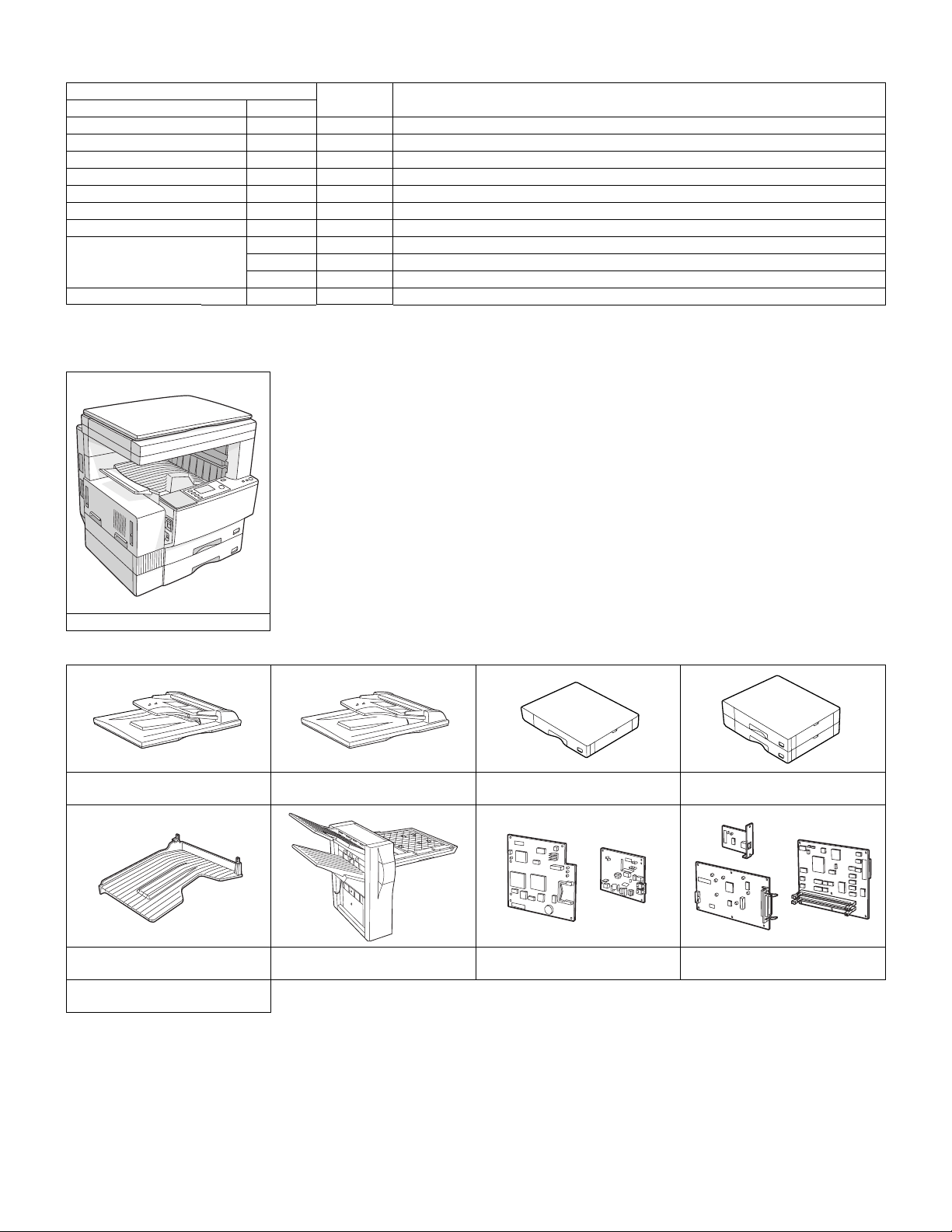
2. System outline (Options)
Option
Item Model
Reversing single pass feeder AR-RP3 Y
Single pass feeder AR-SP4 Y
500-sheet paper feed unit AR-D11N Y
2X500-sheet paper feed unit AR-D12N Y
Job separator tray kit AR-TR3 Y
Finisher AR-FN5N Y For connection of the sort and staple, the AR-EB4 is required.
Facsimile expansion kit AR-FX4 Y
Fax memory 2MB AR-MM5 Y
4MB AR-MM6 Y
8MB AR-MM7 Y
Dual function board AR-EB4 Y
Y: Installable
For details of the options, refer to the Service Manual of each option.
Main unit
model
NOTE
(1) Main units
AR-5127
(2) Options
AR-RP3
Reversing single pass feeder
AR-TR3
Job separator tray kit
AR-MM5/MM6/MM7
2/4/8MB Fax memory
AR-SP4
Single pass feeder
AR-FN5N
Finisher
AR-D11N
500-sheet paper feed unit
AR-FX4
Facsimile expansion kit
2X500-sheet paper feed unit
AR-D12N
AR-EB4
Dual function board
AR-5127 SYSTEM CONFIGURATION 2 - 2
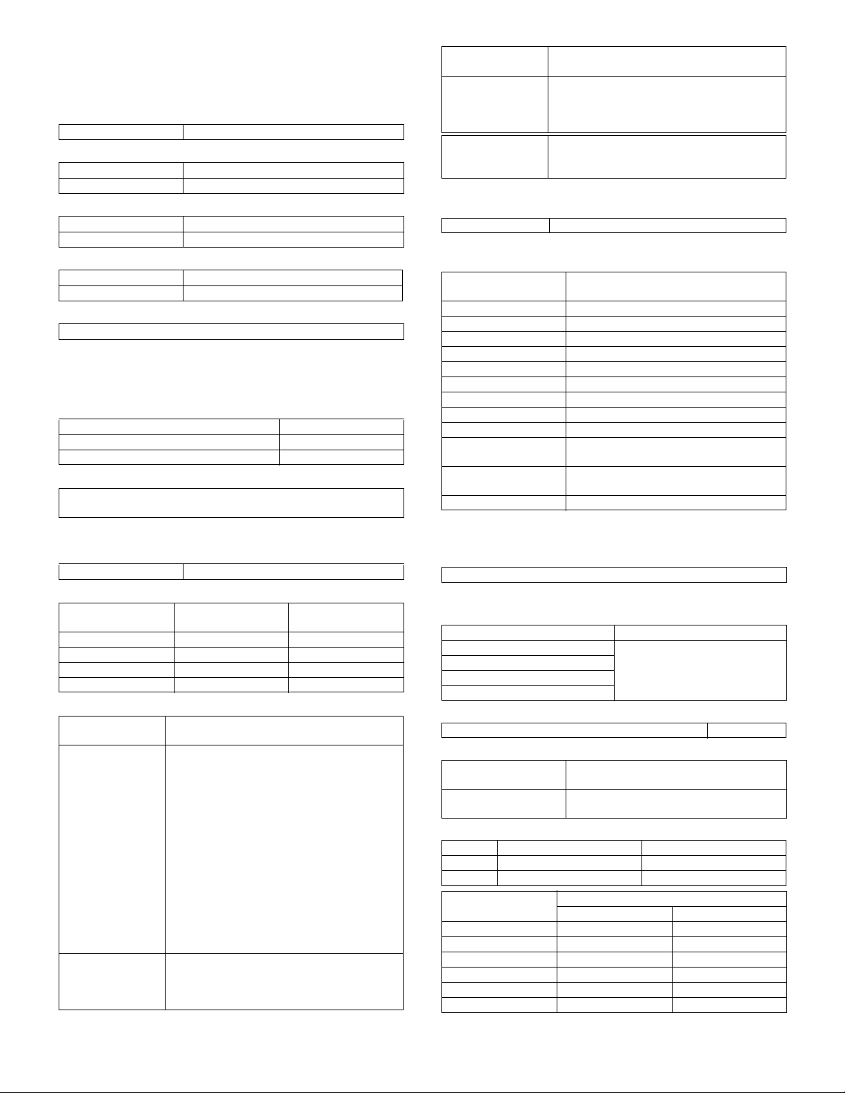
[3] SPECIFICATIONS
1. Basic specifications
(1) Type
Machine Type Desktop type
(2) Target users
Average 10,000 to 13,000 sheets/month
Max. 50,000 sheets/month
(3) External dimensions
Packaged 780 (W) × 760 (D) × 840 (H)mm
Body 623 (W) × 585.5 (D) × 640.5 (H)mm
(4) Weight
Packaged About 55.95 kg
Copier body 42.5 kg
(5) Machine life
800,000 sheets or 5 years
2. Operation specifications
A. Common operation
(1) Warm up time
After turned on Under 40 seconds
Recovery from power-save mode Under 10 seconds
Recovery from paper jam 10 sec.
(2) Jam recovery time
About 10sec (Leaving the machine for 60 sec after opening the door,
standard condition, polygon stop.)
B. Copy mode
(1) Document size
Max. document size A3 paper (11" × 17")
(2) Picture quality mode
Picture quality mode
Auto mode 1 step Selectable
Character mode 5 steps Selectable
Text/Photo mode 5 steps Selectable
Photo mode 5 steps —
Density adjustment
step
(3) Copy magnification ratio
Copy magnification
ratio
Fixed magnification
mode
Zoom width Standard: 50 to 400% (50 to 200% for SPF/
Magnification range/fixed magnification
Standard 4R+5E
AB Series: 50, 70, 81, 86, 100, 115, 122, 141,
200, 400%
Inch Series: 50, 64, 77, 95, 100, 121, 129,
141, 200, 400%
(However, 400% is inhibited when SPF/RSPF
is used.)
With AR-EB4 installed, 5R+5E
AB Series: 25, 50, 70, 81, 86, 100, 115, 122,
141, 200, 400%
Inch Series: 25, 50, 64, 77, 95, 100, 121, 129,
141, 200, 400%
(However, 400% is inhibited when SPF/RSPF
is used.)
RSPF)
With AR-EB4 installed: 25 to 400% (50 to
200% for SPF/RSPF)
Toner save mode
Copy magnification
ratio
Independent
magnification width
Magnification
precision
Magnification range/fixed magnification
Standard: 50 to 400% for horizontal/
vertical (50 to 200% for SPF/RSPF)
With AR-EB4 installed: 25 to 400% for
horizontal/vertical (50 to 200% for SPF/RSPF)
Normal copy: 100%±1.0%
Enlargement copy: Set magnification ±1.0%
Reduction copy: Set magnification ±1.0%
(4) Job speed
a. First Copy Time
Normal Less than 4.8 seconds (when the single copy)
b. Multi copy speed (sheets/minute)
• Copy magnification
Document Size
A3 15
B4 17
A4 (Horizontal feed) 27
A4 (Vertical feed) 18
B5 (Horizontal feed) 27
B5 (Vertical feed) 21
11" × 17" 15
8-1/2" × 14" 16
8-1/2" × 13" 17
8-1/2" × 11" (Horizontal
feed)
8-1/2" × 11" (Vertical
feed)
A5/INV 27
∗
The slowest speed is listed in enlargement/reduction copy.
∗
Single-side copy
(Normal copy/Reduction copy (50% to
99%)/Enlargement copy (100% to 200%)
27
18
(5) Max. multi-copy (print) quantity
999 sheets
(6) Picture quality
a. Image process
Picture quality mode Image process (Software)
Auto mode • 2 gradations
Text mode
Text/Photo mode
Photo mode
b. Toner save mode
Set with the key operator program. Default: ON
c. Zoom method
Main scanning
direction
Sub scanning direction Performed by image processing and
d. Resolution
Main scanning direction Sub scanning direction
Scan 400 dpi 600 dpi
Output 600 dpi 600 dpi
Copy magnification
ratio
25% to 49% — —
50% to 69% 3.2 line/mm 2.8 line/mm
70% to 94% 3.6 line/mm 3.2 line/mm
95% to 105% 5.0 line/mm 4.5 line/mm
106% to 141% 5.0 line/mm 4.5 line/mm
142% to 400% 5.0 line/mm 4.5 line/mm
Performed through image processing
changing scanning speed
• Area separation
• Error diffusion
Position
Center Corners
AR-5127 SPECIFICATIONS 3 - 1

e. Gradation
Read 256 gradations
Write 2 gradations
3. Engine specifications
A. Operation and display section
Display unit LED display system
Operation system Button switch system
B. Paper feed, transport, paper exit section
(1) Paper feed ability
Paper feed
section
Paper feed
capacity
Document Size AB Series: A3 to A6R
Remaining
detection
• Details of paper feed section
Capacity —
Paper weight 56 to 80 g/m² (15 to 21.3 lbs)
Document Size AB Series: A3/B4/A4/A4R/B5/B5R/A5
Paper kind Standard paper (56 to 80 g/m²), special paper
Special paper Reproduction paper
Paper size
selection
Slide switch —
Cassette
attachment/
detachment
Remarks A5, B5, 8.5 x 5.5 (only for upper cassette)
• Manual feed section
Capacity 100 sheets (52g to 80g/m²)
Paper weight 52 to 128 g/m² (14 to 34.1 lbs)
Document Size AB Series: A3 to A6R
Paper kind Multi feed: Standard paper (52 to 80 g/m²),
Size detection Yes
Guide display A3/A4,11,B4/B5,8.5,A4R/A5,B5R,A5R,5.5
∗
When poor image quality is resulted by the use of OHP sheet, adjust
with SIM 44-34.
(2) Finishing ability
Paper exit section Paper exit tray (1 tray)
Capacity 500 sheets
(3) Job separator exit tray (AR-TR3)
a. Condition
In case of Optional function (printer, FAX) is set up as MFD.
b. Simultaneous wrapping in kit
Job separator tray
Setting manual book
c. Simultaneous wrapping
Setting manual book
2 cassettes + multi manual feed
500×2+100
Inch Series: 11"×17" to 8.5"×5.5"
Cassette section: empty detection only available
Manual paper feed section: empty detection only
available
Inch Series: 8.5×11/8.5×14/11×17/8.5×13/
8.5×11R/8.5×5.5
User operation (LCD panel operation)
Yes
B5 is not applicable to lower cassette (2nd
stage).
Inch Series: 11"×17" to 8.5"×5.5"
special paper (Reproduction paper/OHP/label
paper/postcard/envelope)
Single feed: Standard paper (52 to 128 g/m²),
special paper (Reproduction paper/OHP/label
paper/postcard/envelope)
d. Function
This exit tray is set up above main exit tray, and can separate copier
exit, printer exit and FAX exit.
e. Many of tray
1 (this tray can not set up more than 2)
f. Separator system
by control of main machine
g. Exit paper size
Upper exit tray (Job separator
tray)
Lower exit tray (Main machine
exit tray)
h. Exit paper weight
52 to 128g/m
i. Paper pass
center (same as main unit)
j. Exit area/finishing
Upper exit tray (Job separator tray) Face down
Lower exit tray (main machine exit tray) Face down
k. Power supply
Power supply DC 24V (from main machine)
Power consumption 5.6W
l. Method of movement
with original motor (not with main machine)
m. Machine weight
0.6 kg
n. Exit capacity
Upper exit tray (Job separator) 100 sheets
Lower exit tray (main machine exit tray) 500 sheets (
∗
400 sheets for B4, Legal, Foolscap, A3, and W letter.
o. Tray full detector
Upper exit tray (Job separator) Yes
Lower exit tray (main machine exit tray) No
p. Concept of function
Upper exit tray (Job separator) FAX/Printer (This setting can be
Lower exit tray (main machine
exit tray)
q. Reliance
MCBJ 60k
MCBF 10k
r. Main color of cabinet
Frosty white
s. Setting
to be easy setting
2
(14 to 34.1lbs)
AB system A3 to A6
Inch system 11 x 17 to 8.5 x 5.5
AB system A3 to A6
Inch system 11 x 17 to 8.5 x 5.5
∗
)
done by users.)
Copy/Printer/FAX (This setting can
be done by users.)
C. Optical (Image scanning) section
(1) Type
Flat-bed type/monochrome
(2) Document reference position
Rear left reference
(3) Resolution
Main scanning direction Sub scanning direction
Scan 400 dpi 600 dpi
(4) Gradation
256 gradations (8-bit)
AR-5127 SPECIFICATIONS 3 - 2
(5) Original size/Scanning area
a. Max. original size
A3 paper (11" × 17")
b. Scanning area
356 mm
CENTER
F. Fusing
Type Heat roller
Lamp Type Halogen lamp
Voltage 100V
Power
consumption
Fusing temperature 185° (600 dpi)
Heat roller Teflon coated roller
Pressure roller Silicone rubber roller with roentgerized
Separation system Natural separation (with pawl)
1000W
160° (1200 dpi)
cube
G. Drive
Drive section Motor
Main motor DC brushless motor
4. Safety and environmental protection
standards
216 mm
(6) Scanning speed
122mm/sec (600 dpi: magnification ratio 100%)
(7) Light source (lamp)
Type Xenon
Drive voltage 1.5 kV
(8) Read sensor
Type Reduction optical system image sensor (CCD)
Monochrome
D. Scanner (exposure) section
(1) Resolution
Main scanning direction Sub scanning direction
600 dpi 600 dpi
(2) Gradation
2 gradations
(3) Laser unit specifications
r.p.m. 28,800 rpm
Mirror surfaces 6 faces
Laser power 0.4mW/600dpi, 0.2mW/1200dpi
Laser beam size 60
Laser wave length 785nm
µ (
Main scan) x 70µ (Sub scan)
E. Image process section
Imaging speed 600 dpi : 122 mm/sec.
Photo
conductor
Toner Type Developer (Black)
Charge System (–) DC scorotron (saw tooth)
Transfer System Transfer roller
Exposure Xenon lamp
Developing Dry, 2-component magnetic brush
Separation (–) DC corotron
Discharge —
Cleaning Blade
Type OPC drum (dia. 30mm)
LIFE 50,000 sheets
LIFE 33,000 sheets (Toner, life: 33k, Developer life:
50k)
Voltage 560
Voltage 18
µ
A constant electric current
µ
A (electric current)
development
(1) Safety and environmental protection standards
Item Standard name Country name
Safety
standards
Radio wave
noise standard
EnergyStar World-wide
S mark Japan
SEMKO mark EU
CE mark EU
(2) Ozone level
Ozone Less than 0.02mg/m³
Dust Less than 0.075mg/m³
(3) Noise level
Operating Less than 63dB
On standby Less than 40dB
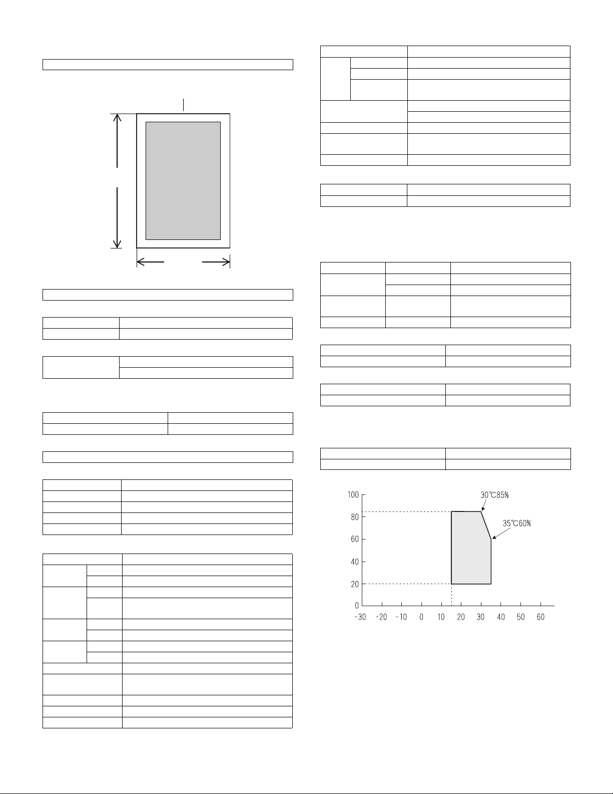
5. Environment conditions
(1) Space required
Folded multi manual feed 623 (W) × 585.5 (D) mm
Open multi manual feed 889 (W) × 585.5 (D) mm
(2) Operating ambient conditions
Humidity (%)
Temperature (˚C)
AR-5127 SPECIFICATIONS 3 - 3
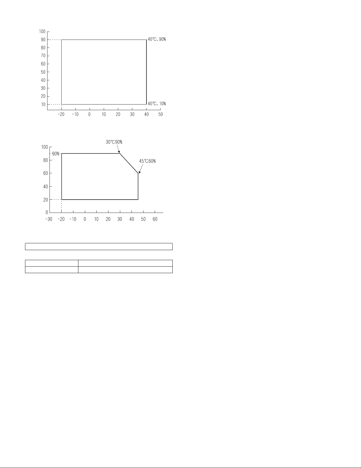
(3) Ambient storage conditions
Humidity (%)
Temperature (˚C)
(4) Ambient conditions for transporting
Humidity (%)
Temperature (˚C)
(5) Atmospheric pressure
595 mmHg or above
(6) Standard temperature and humidity
Temperature 20 to 25°C
Humidity 65±5%RH
AR-5127 SPECIFICATIONS 3 - 4

[4] CONSUMABLE PARTS
1. List
A. LAG
No. Item Content Life Model name Remarks
1 Toner CA (Black) with
IC chip
2 Developer Developer
3 Drum Drum ×1 50K AR-270DR
4 Upper heat roller kit Upper Heat Roller
5 Lower heat roller kit Lower Heat Roller
6 100K maintenance kit Drum Separation Unit
7 MC unit MC unit ×10 50K (×10) AR-270MC
8 Cleaner Blade Cleaner Blade ×10 50K (×10) AR-270CB
9 Drum frame unit Drum frame unit ×1 200K AR-270DU * The life of the toner reception seat welded to
10 Staple Cartridge Staple Cartridge ×3 3000 staples ×3AR-SC1
Toner
(Toner; Net Weight 745g)
Polyethylene Bag
(Developer; Net Weight 400g)
Fusing gear
Upper heat roller bearing
Fusing separation pawl (upper)
Fusing separation pawl (lower)
Fusing busing (lower)
Transfer roller unit
×10 33K (×10) AR-270MT * Life: A4 size at 6% coverage
×10
×10 50K (×10) AR-270MD MD=ND*10
×1
×1
×2
×4
×1
×4
×2
×2
×1
150K AR-271UH
300K AR-271LH
100K AR-271KA1
the drum frame is 200K, and it can be used up
to 4 times. (Supplied as a drum frame unit.)
* Drum frame unit contains all the drum unit
parts excluding Drum and Drum fixing plate.
MT=NT*10
* The other maintenance parts than the above are supplied as service parts.
B. SMEF (Middle East, Africa)/Israel
No. Item Content Life Model name Remarks
1 Toner CA (Black) with
IC chip
2 Developer Developer
3 Drum Drum ×1 50K AR-270DR
4 Upper heat roller kit Upper Heat Roller
5 Lower heat roller kit Lower Heat Roller
6 100K PM kit Drum Separation Unit
7 MC unit MC unit ×10 50K (×10) AR-270MC
8 Cleaner Blade Cleaner Blade ×10 50K (×10) AR-270CB
9 Drum frame unit Drum frame unit ×1 200K AR-270DU * The life of the toner reception seat welded to
* The other maintenance parts than the above are supplied as service parts.
Toner
(Toner; Net Weight 745g)
Polyethylene Bag ×10
(Developer; Net Weight 400g)
Fusing gear
Upper heat roller bearing
Fusing separation pawl (upper)
Fusing separation pawl (lower)
Fusing busing (lower)
Transfer roller unit
DV blade
Side seal F
Side seal R
×10 33K (×10) AR-270ET * Life: A4 size at 6% coverage
×10 50K (×10) AR-270CD CD=SD*10
×1
×1
×2
×4
×1
×4
×2
×2
×1
×1
×1
×1
ET=FT*10
150K AR-271UHG
300K AR-271LH
100K AR-271KA
the drum frame is 200K, and it can be used up
to 4 times. (Supplied as a drum frame unit.)
* Drum frame unit contains all the drum unit
parts excluding Drum and Drum fixing plate.
AR-5127 CONSUMABLE PARTS 4 - 1

C. Asia affiliates/Asia agent/STCL/SRH/SRS/SRSSC/SBI
No. Item Content Life Model name Remarks
1 Toner CA (Black) with
IC chip
2 Developer Developer
3 Drum Drum ×1 50K AR-270DR
4 Upper heat roller kit Upper Heat Roller
5 Lower heat roller kit Lower Heat Roller
6 100K PM kit Drum Separation Unit
7 MC unit MC unit ×10 50K (×10) AR-270MC
8 Cleaner Blade Cleaner Blade ×10 50K (×10) AR-270CB
9 Drum frame unit Drum frame unit ×1 200K AR-270DU * The life of the toner reception seat welded to
10 Staple Cartridge Staple Cartridge ×3 3000 staples ×3AR-SC1
Toner
(Toner; Net Weight 745g)
Polyethylene Bag ×10
(Developer; Net Weight 400g)
Fusing gear
Upper heat roller bearing
Fusing separation pawl (upper)
Fusing separation pawl (lower)
Fusing busing (lower)
Transfer roller unit
DV blade
Side seal F
Side seal R
×10 33K (×10) AR-270CT * Life: A4 size at 6% coverage
×10 50K (×10) AR-270CD CD=SD*10
×1
×1
×2
×4
×1
×4
×2
×2
×1
×1
×1
×1
CT=ST*10
150K AR-271UHG
300K AR-271LH
100K AR-271KA
the drum frame is 200K, and it can be used up
to 4 times. (Supplied as a drum frame unit.)
* Drum frame unit contains all the drum unit
parts excluding Drum and Drum fixing plate.
* The other maintenance parts than the above are supplied as service parts.
AR-5127 CONSUMABLE PARTS 4 - 2
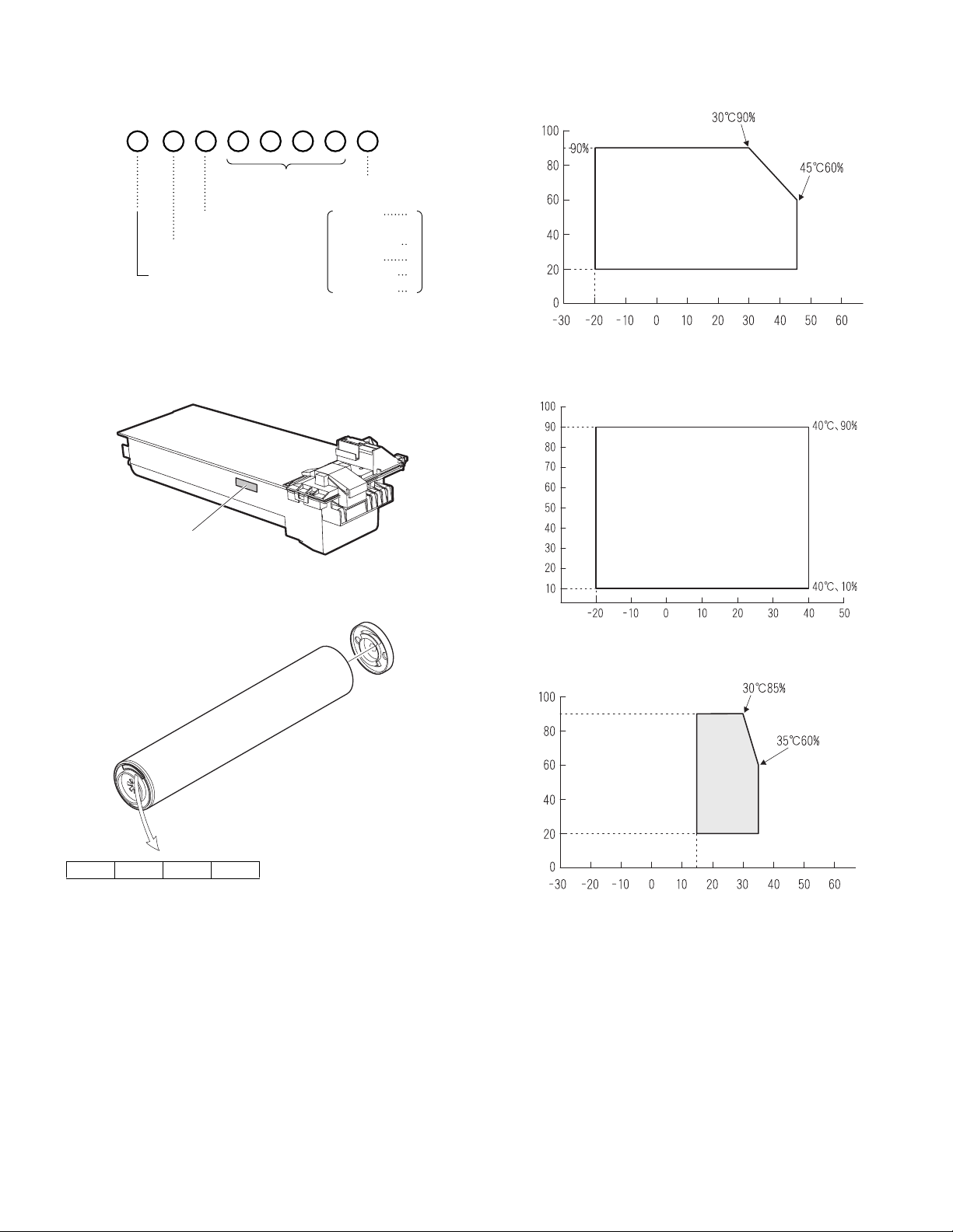
2. Production number identification
3. Environment conditions
<TD cartridge>
The label on the TD cartridge shows the date of production.
Serial number
(0001-9999)
Unit version
Destination
The end digit of
production year
Label position
Production
month
January
~
September
October
November
December
A. Ambient conditions for transporting
1
~
9
0
X
Y
Humidity (%)
Temperature (˚C)
B. Ambient storage conditions (sealed)
Humidity (%)
<Drum>
The laser print indicates the date (year, month, day) of production.
1234
1 The last digit of the production year.
2 The prodoction month.
X stands for October, Y November, and Z December.
3, 4 Production date.
Temperature (˚C)
C. Operating ambient conditions
Use environment
conditions
Humidity (%)
Temperature (˚C)
4. Life (packed conditions)
Photoconductor drum (36 months from the production month)
Developer, toner (24 months from the production month)
AR-5127 CONSUMABLE PARTS 4 - 3
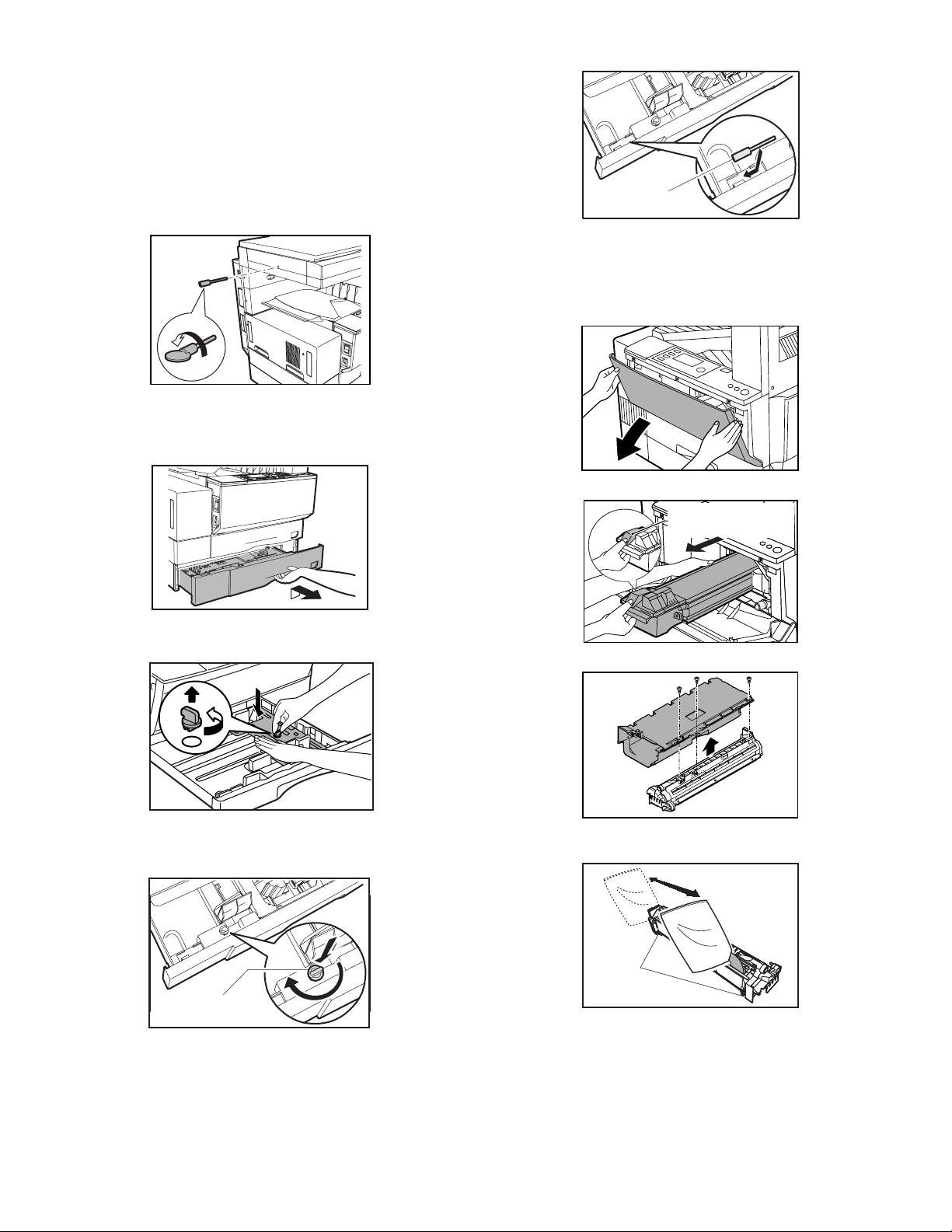
[5] UNPACKING AND INSTALLATION
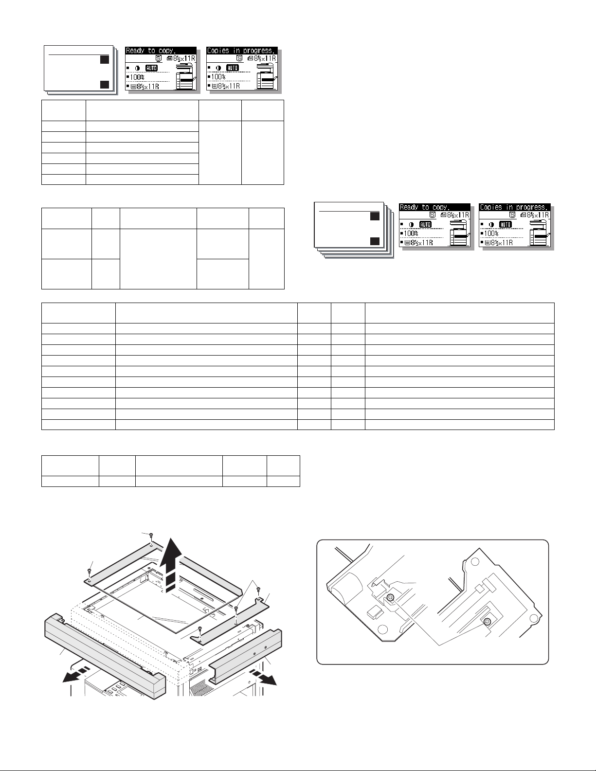
1. Removal of protective material and fixing
screw
1) Remove all tapes, then open the document cover and remove the
protective material of sheet shape.
2) Remove the fixing screw using a coin.
The fixing screw is required when transporting the machine. Keep
it in the tray. (Refer to the later description.)
2. Removal and storage of fixing pin
1) Lift the knob and gently pull out the tray.
Fixing screw
∗
If power is turned don without removing the fixing pin, it will be difficult to pull out the tray.
3. Developer cartridge installation
1) Hold the both sides of the front cover, and pull down to open it.
2) Loosen the screw and remove the developer cartridge.
2) Hold the paper pressure plate and turn the fixing pin in the arrow
direction.
3) Store the removed fixing pin and the fixing screw which was
removed in the above procedure, together in the specified storage
place in the tray.
TD cartridge lock
release lever
3) Remove the developer tank from the developer cartridge.
4) Supply developer into the developer tank while rotating the MG
roller.
Fixing pin
∗
Shake the developer bag enough before opening it.
∗
Check to insure that the hook is engaged in two positions.
5) Attach the developer tank to the developer cartridge.
After supplying developer into the developer cartridge, do not tilt or
shake the developer cartridge.
6) Attach the developer cartridge to the copier, and fix it with the
screw.
Note: When replacing the OPC drum with a new one, be sure to clear
the drum count.
AR-5127 UNPACKING AND INSTALLATION 5 - 1
Hook
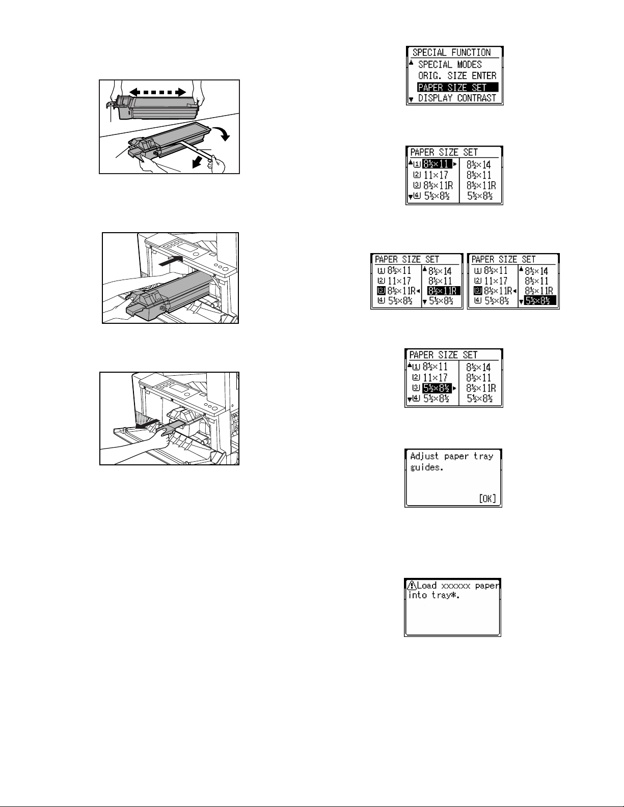
4. Toner cartridge installation
1) Shake the toner cartridge several times horizontally, and remove
the tape.
4 or 5 times
Shutter
Tape
Knob
∗
Do not hold the shutter lever when shaking.
2) Press the lock release lever, and insert the unit completely into the
copier along the guide groove. Then fix the blue screw and the
locking screw.
∗
Dirt or dust must be removed from the toner cartridge before
installing.
3) Take off the tape, and remove the shutter from the toner cartridge.
• Screen display
3) On the screen, all trays are indicated and the previously selected
tray is highlighted. Use the Up/Down key to select the tray desired.
• Screen display
4) After selecting the tray, press the Right cursor key to move to the
paper size selection box on the right side of the screen (the highlighted size is the previously selected size). Use the Up/Down key
to select the desired paper size.
5) After selecting the paper size, press the Left cursor key to return to
the left side of the screen. At that time, the selected tray indicates
the paper size selected above.
5. Toner concentration sensor level
adjustment
1) Open the cover.
2) Power ON (The mechanism cannot be initialized because the
cover is open.)
3) Install the developing unit with new developer in it.
4) Enter SIM 25-2.
5) Close the cover immediately before starting the operation.
6) Press the OK key to start.
After completion of the adjustment, be sure to cancel the simulation.
Note: When replacing developer with new one, be sure to clear the
developer counter.
6. Paper size selection for paper feed tray
1) The paper feed trays have no paper size detection mechanism and
the paper size can be selected by entry from the operation panel.
The bypass tray has a paper size detection mechanism and the
paper size cannot be selected from the operation panel.
2) To select the paper size from the operation panel, press the Spe-
cial Function key and choose "Paper Size Enter" from the function
menu to open the paper size enter screen.
Press the OK key to confirm the setting. The following message
appears:
• Message (M081)
6) After the Start key is pressed, if the fed paper is different in size
from the setting, the machine makes copy and then stops running
with the mode retained. The following message appears for six
seconds. the Start LED is ON): The tray set EXTRA size is not
available for this specification.
• Message (C449)
7) If any of Trays 2 to 4 is selected, the paper sizes of A5/5.5 x 8.5 are
not available (because the A5/5.5 x 8.5-sized paper cannot be fed
from these trays).
AR-5127 UNPACKING AND INSTALLATION 5 - 2
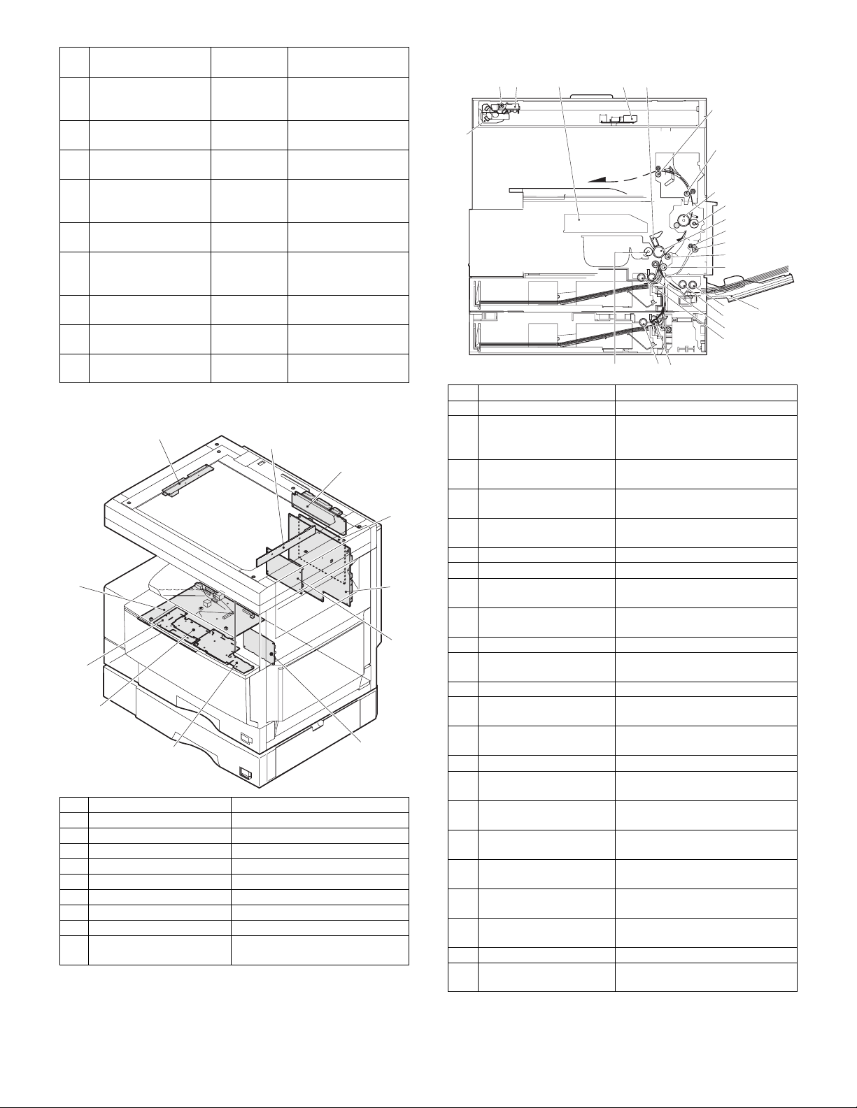
[6] EXTERNAL VIEW AND INTERNAL STRUCTURE
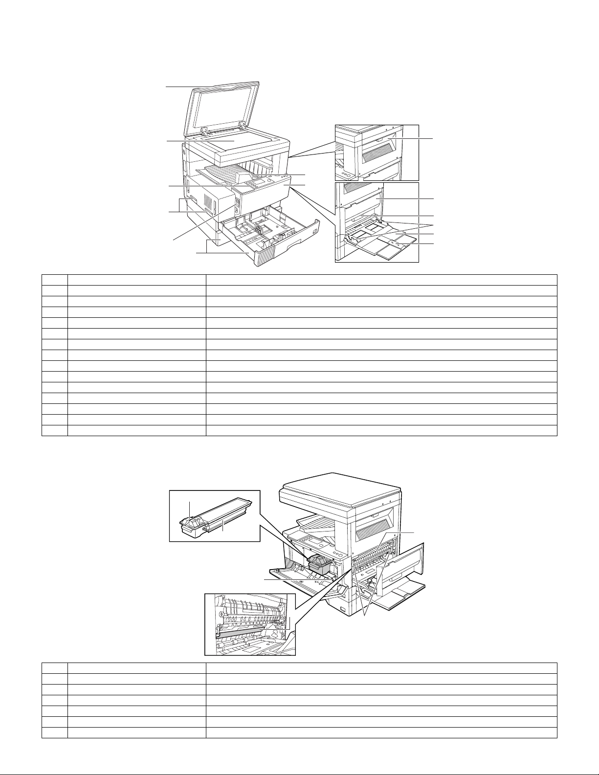
1. External view
1
8
2
7
6
5
4
3
9
10
11
12
13
14
No. Name Function/Operation
1 Platen cover Place the original on the original table and close the platen cover before copying starts.
2 Paper output tray Finished copies are deposited in the paper output tray.
3 Front cover Open to remove misfeeds and for copier servicing.
4 Paper trays Each tray holds 500 sheets of copy paper.
5 Power switch Press to turn copier power on and off.
6 Handles Use to move the copier.
7 Operation panel All copier controls are located here for easy operation.
8 Original table Place the document to be copied here.
9 Upper exit area cover Open to remove misfeeds when an optional job separator tray kit or finisher is installed.
10 Side cover Open to remove misfeeds.
11 Side cover handle Lift and pull to open the side cover.
12 Bypass tray guides Adjust to the width of the copy paper.
13 Bypass tray Special papers (including transparency film) and copy paper can be fed from the bypass tray.
14 Bypass tray extension Pull out when feeding large paper such as 8-1/2" x 14" and 11" x 17".
2. Internal
1
2
3
4
5
No. Name Function/Operation
1 Toner cartridge lock release lever Use to unlock the toner cartridge.
2 Toner cartridge Contains toner.
3 Paper guide Open to remove misfed paper.
4 Fusing unit release levers Lower to remove misfed paper.
5 Photoconductor drum A drum on which photoconductor is coated. Images are formed on this photoconductor drum.
6 Roller rotating knob Turn to remove misfed paper.
6
AR-5127 EXTERNAL VIEW AND INTERNAL STRUCTURE 6 - 1
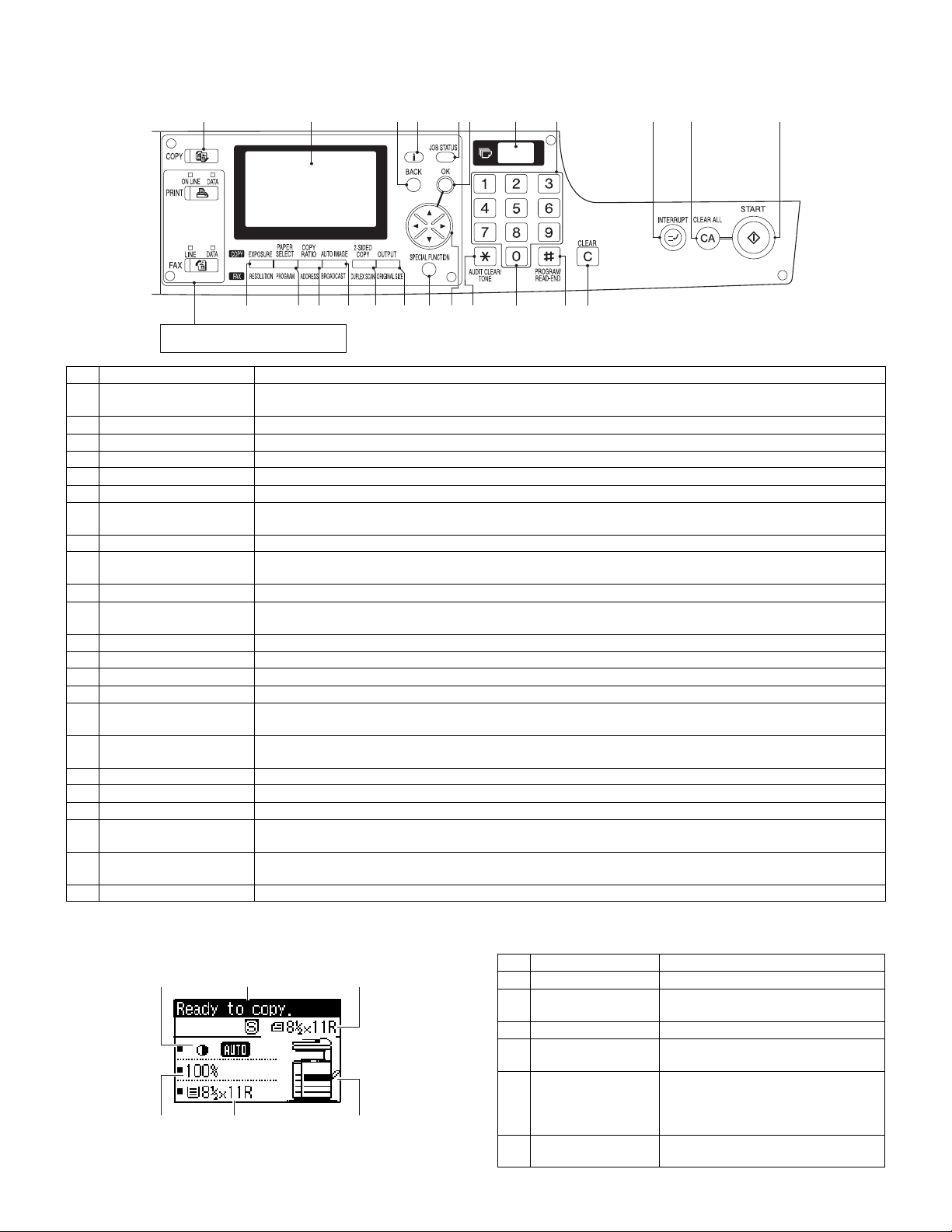
3. Operation panel
A. Key position
1
12 13 14 15 16 17 18 19 20 21 22 23
These keys and indicators are not used
for the copier features
No. Name Function/Operation
1 COPY key and indicator Press to select the COPY mode.
2 Display Displays information to assist the operator.
3 BACK key Press to return the display to the previous screen.
4 Information key Press to display the detailed description when [i] is displayed at the upper right of the display.
5 JOB STATUS key Press to check the settings of selected functions or the status of reserved output jobs.
6 OK key Press to register the selected setting.
7 Copy quantity display Displays the specified copy quantity during the ready condition and displays the copy countdown as copies are
8 Numeric keys Used to select the desired copy quantity.
9 INTERRUPT key and
indicator
10 CLEAR ALL key Clears all selected settings and returns the copier to the initial settings.
11 START key and indicator Copying is possible when the indicator is on.
12 EXPOSURE key Used to select the exposure modes: AUTO, TEXT, TEXT/PHOTO, PHOTO or SUPER PHOTO.
13 PAPER SELECT key Used to manually select a paper tray.
14 COPY RATIO key Press to select a reduction or enlargement copy ratio.
15 AUTO IMAGE key Press for automatic copy ratio selection.
16 2-SIDED COPY key Press to select the 1-sided to 1-sided, 1-sided to 2-sided, 2-sided to 1-sided* or 2-sided to 2-sided* copy mode.
17 OUTPUT key Press to select the sort, group or staple sort* mode.
18 SPECIAL FUNCTION key Press to select special functions.
19 Arrow keys Press to move the highlighted item in the display.
20 AUDIT CLEAR key Press to close an open account.
21 Zero key Use as part of numeric keys to enter copy quantity.
22 PROGRAM/READ END
key
23 CLEAR key Press to clear the copy quantity display or press during a copy run to terminate copying.
Press and hold during standby to display the total output count. Quantity of toner remaining is also displayed.
made.
Interrupts a copy run.
Press to start copying.
*To select the 2-sided to 1-sided or 2-sided to 2-sided copy mode, an optional RSPF must be installed.
*To select the staple sort mode, an optional finisher must be installed.
Press during a continuous copy run to display the number of copies completed in the current run.
Press to select the job memory mode.
Press to finish scanning of originals and to start copying when copying from the original table.
2 3 4 5 6 7 8 9 10 11
B. LCD panel
(Basic screen)
231
4
56
AR-5127 EXTERNAL VIEW AND INTERNAL STRUCTURE 6 - 2
No. Name Function/Operation
1 Exposure display Indicates the selected exposure mode.
2 Message display Messages are displayed regarding
copier status and operation.
3 Original size display The original paper size is displayed.
4 Copy ratio display Displays the copy ratios for reductions
or enlargements.
5 Paper size display Displays the selected paper size.
When "AUTO" is displayed, paper size
matching the original and copy ratio
will be automatically selected.
6 Paper tray display The selected paper feed location is
highlighted.
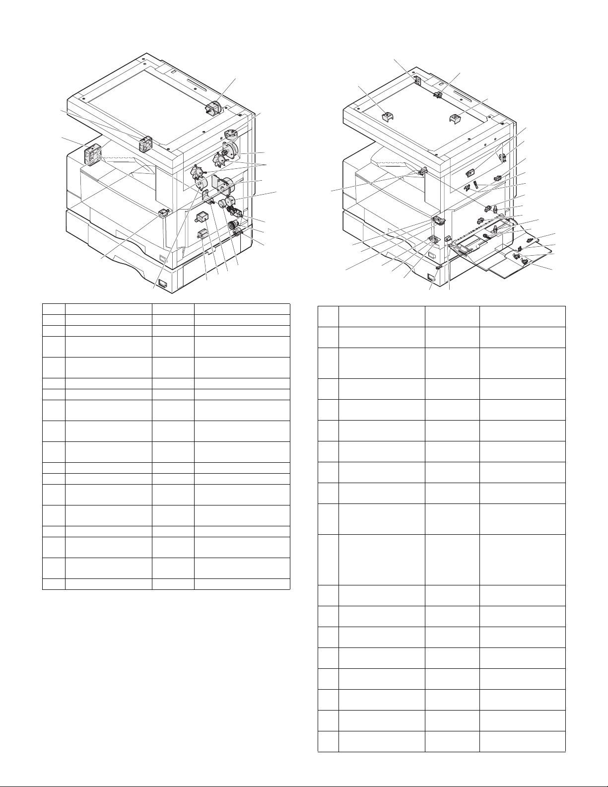
4. Motor, Solenoid, Clutch 5. Sensor
1
17
2
16
3
4
5
7
8
9
15
13
12
11
10
14
No. Name Code Function and operation
1 Mirror motor MIRM Optical mirror base drive
2 Shifter motor SFTM Shifter drive
3 Duplex motor
4 Cooling fan
DPXM
TFAN
Duplex paper switching
and exit roller
Cools the inside of the
unit.
5 Main motor MM Main drive
6 PS clutch PSRSOL Main unit paper feed
7 Manual paper feed
solenoid
8 Manual paper feed
clutch
9 Paper feed transfer
clutch
HPSOL
Manual paper feed
solenoid
Manual paper feed
clutch
Paper feed transfer
clutch
10 Paper feed clutch PCL1H Paper feed roller drive
11 Cassette lift-up motor LUM1H Cassette paper lift-up
12 Paper feed solenoid
PCS1H
Solenoid for the paper
feed from the cassette
13 2nd cassette paper
feed solenoid
14 Toner motor TM Toner supply
15 Separation pawl
solenoid
16 Exhaust fan motor
PREMSOLSeparation pawl
operation solenoid
PSFAN
Cools the inside of the
unit.
17 Intake fan motor
6
26
No. Name Code
1
25
24
27
1 Original size sensor DSIN0 Document size
2 Mirror home position
sensor
3 Document cover
sensor
4 Document size sensor DSIN3 Document size
5 1st paper exit sensor POUT 1st paper exit
6 Shifter home position
sensor
7 Paper exit sensor
(DUP side)
8 Thermistor RTHIN Fusing temperature
9 Thermostat Abnormal high
10 Manual feed paper
entry sensor
11 1st cassette (paper
tray) detection
12 Manual feed paper
empty sensor
13 2nd cassette (paper
tray) detection
14 Manual feed width
detection volume
15 Manual paper feed
tray empty sensor 2
16 Manual paper feed
tray empty sensor 1
17 Manual feed length
detection sensor 2
18 Manual feed length
detection sensor 1
23
22
2
3
4
5
6
7
8
9
10
11
12
13
14
15
16
17
18
21
20
19
Function and
operation
detection
MHPS Mirror (scanner)
home position
detection
OCCOVER Document cover
open/close detection
detection
detection
SFTHP Shifter home position
sensor detection
PDPX Paper exit detection
detection
temperature detection
in the fusing section
HPIN Sensor of paper entry
from the manual
paper feed tray, the
2nd/multi-stage desk,
or the DUP
CSS1 1st cassette (paper
tray) empty detection
HPEMPTY Manual feed paper
empty detection
CSS1A 2nd cassette (paper
tray) empty detection
HPWS Manual feed paper
width detection
HPTRAY2 Manual feed tray
position detection
HPTRAY1 Manual feed tray
position detection
HPSIZE2 Manual feed paper
length detection
HPSIZE1 Manual feed paper
length detection
AR-5127 EXTERNAL VIEW AND INTERNAL STRUCTURE 6 - 3
No. Name Code
19 Door switch SW24V Front door and side
20 2nd right door switch DRS1A Side door open/close
21 2nd cassette paper
pass sensor
22 2nd cassette paper
upper limit detection
sensor
23 2nd cassette paper
empty sensor
24 1st cassette paper
upper limit detection
sensor
25 1st cassette paper
empty sensor
26 Center tray paper
YES/NO sensor
27 1st cassette paper
pass sensor
PPD1A 2nd cassette paper
LUD1A 2nd cassette paper
PAP1A 2nd cassette paper
LUD1H 1st cassette paper
PAP1H 1st cassette paper
TRAYPAPER
PIN 1st cassette paper
Function and
operation
door open/close
detection
detection
pass
upper limit detection
empty detection
upper limit detection
empty detection
Center tray paper
YES/NO detection
pass
6. PWB unit
1
11
10
9
8
No. Name Function and operation
1 Inverter PWB Copy lamp control
2 CCD PWB For image scanning (read)
3 Option connector PWB
4 MCU PWB Main unit control
5 Tray interface PWB 2nd tray control
6 KEY/LED PWB (right side) For the copy operation
7 LCD back light PWB LCD control
8 KEY/LED PWB (left side) For the FAX operation
9 Power source PWB AC power input/DC voltage
2
3
7
control
7. Section
12 3 4 5
6
23
22
No. Name Function and operation
1 Copy lamp Image radiation lamp
2 Copy lamp unit Operates in synchronization with
3 LSU unit Converts image signals into laser
4 Lens unit Reads images with the lens and
4
5
6
5 MC holder unit Supplies negative charges evenly
6 Paper exit roller Paper exit roller
7 Transport roller Paper transport roller
8 Upper heat roller Fuses toner on paper.
9 Lower heat roller Fuses toner on paper.
10 Drum unit Forms images.
11 DUP transport follower
roller
12 DUP transport roller Duplex paper transport
13 Transport roller Transfer images on the drum onto
14 Resist roller Synchronize the paper lead edge
15 Manual feed tray Manual feed paper tray
16 Manual paper feed roller Picks up papers in manual paper
17 Manual feed transport
roller
18 1st cassette pick-up
roller
19 1st cassette paper feed
roller
20 2nd cassette pick-up
roller
21 2nd cassette paper feed
roller
22 MG roller Puts toner on the OPC drum.
23 2nd/3rd mirror unit Reflects the images from the copy
21
20
2nd/3rd mirror unit to radiate
documents sequentially.
beams to write on the dum.
the CCD.
on the drum.
(with the teflon roller)
(with the silicone rubber roller)
Duplex paper transport
paper.
with the image lead edge.
feed port.
Transports paper from the manual
paper feed port.
Picks up paper from the cassette.
Transports the picked up paper to
RESIST section.
Picks up paper from the cassette.
Transports the picked up paper to
RESIST section.
lamp unit to the lens unit.
7
8
9
10
11
12
13
14
16
15
17
18
19
AR-5127 EXTERNAL VIEW AND INTERNAL STRUCTURE 6 - 4
[7] ADJUSTMENTS, SETTING
1. List of adjustment items
Section Adjustment item Adjustment procedure/SIM No.
A Process section (1) Developing doctor gap adjustment Developing doctor gap adjustment
(2) MG roller main pole position adjustment MG roller main pole position adjustment
(3) Developing bias voltage adjustment SIM8-1
(4) Grid bias voltage adjustment (High mode) SIM8-2
(5) Grid bias voltage adjustment (Low mode) SIM8-3
B Mechanism section (1) OC image lead edge position/Sub scanning
magnification ratio/Original offset auto adjustment
(2) Print start position adjustment SIM50-5
(3) SPF image lead edge position adjustment SIM50-6
(4) Rear edge void adjustment SIM50-1-6
(5) Paper off center adjustment SIM50-10
(6) Left edge void area adjustment SIM50-1-8
(7) Main scanning direction (FR direction) distortion
balance adjustment
(8) Sub scanning direction (scanning direction)
distortion adjustment
(9) Main scanning direction (FR direction) distortion
adjustment
(10) Main scanning direction (FR direction)
magnification ratio adjustment
(11) Sub scanning direction (scanning direction)
magnification ratio adjustment
(12) Off center adjustment (SPF mode) SIM50-12
(13) OC (SPF) open/close detection position adjustment SIM41-3
(14) Original sensor adjustment SIM41-2, 41-4
(15) SPF white correction pixel position adjustment
(required in an SPF model when replacing the lens
unit)
(16) SPF scan position auto adjustment SIM53-8, SIM46-20, SIM50-6
C Image density
(1) Copy mode SIM46-2
(exposure) adjustment
SIM48-3
No. 2/3 mirror base unit installing position
adjustment
Copy lamp unit installing position adjustment
Winding pulley position adjustment
Rail height adjustment
SIM48-1-1, 48-1-2
a OC mode in copying (SIM 48-1-3)
b RSPF sub scanning direction magnification ratio
(SIM48-1-4, 48-1-5)
SIM63-7
2. Copier adjustment
A. Process section
(1) Developing doctor gap adjustment
1) Loosen the developing doctor fixing screw A.
2) Insert a thickness gauge of 1.5mm to the three positions at 20mm
and 150mm from the both ends of the developing doctor as shown.
150mm
10mm
10mm
20mm
DG:1.55
F
+0.1
DG:1.5
- 0.15
3) Tighten the developing doctor fixing screw.
4) Check the clearance of the developing doctor. If it is within the
specified range, then fix the doctor fixing screw with screw lock.
∗
When inserting a thickness gauge, be careful not to scratch the
developing doctor and the MG roller.
20mm
R
+0.1
DG:1.5
- 0.15
C
+0.15
- 0.2
<Adjustment specification>
Developing doctor gap
F/R both ends (20mm from the both ends):1.5
C (Center)(150mm from the both ends): 1.55
+0.1mm
-0.15mm
+0.15mm
-0.2mm
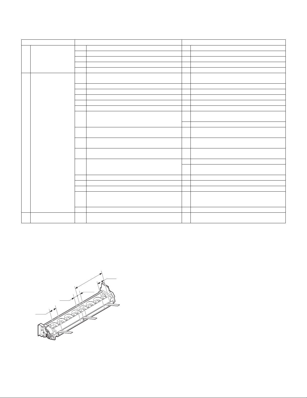
(2) MG roller main pole position adjustment
1) Put the developing unit on a flat surface.
2) Tie a needle or pin on a string.
3) Hold the string and bring the needle close to the MG roller horizontally. (Do not use paper clip, which is too heavy to make a correct
adjustment.) (Put the developing unit horizontally for this adjustment.)
4) Do not bring the needle into contact with the MG roller, but bring it
to a position 2 or 3mm apart from the MG roller. Mark the point on
the MG roller which is on the extension line from the needle tip.
5) Measure the distance from the marking position to the top of the
doctor plate of the developing unit to insure that it is 18mm.
If the distance is not within the specified range, loosen the fixing
screw A of the main pole adjustment plate, and move the adjustment plate in the arrow direction to adjust.
AR-5127 ADJUSTMENTS 7 - 1
A
(3) Developing bias voltage adjustment (SIM 8-1)
1) Execute SIM 8-1.
Sim8-1 DV BIAS COPY
1:AE 400
2:TEXT 450
3:TEXT/PHOTO 450
1/2
2) After selecting the mode, enter the adjustment value and press the
[OK] key.
3) Output will be made for 30 sec.
<Adjustment specification>
Display items Content
1:AE
2:TEXT
3:TEXT/PHOTO
4:PHOTO
5:SUPER PHOTO
6:TONER SAVE
AE 200-550 400 (–400V)
Character 450 (–450V)
Character/Photo 450 (–450V)
Photo 450 (–450V)
Super photo Disabled
Toner save 376 (–376V)
Installation
range
Default
(4) Grid bias voltage adjustment (High mode) (SIM 8-2)
1) Execute SIM 8-2.
(5) Grid bias voltage adjustment (Low mode) (SIM 8-3)
1) Execute SIM 8-3.
Sim8-3 MHV(L) COPY
1:AE 3
2:TEXT 5
3:TEXT/PHOTO 5
1/2
2) After selecting the mode, enter the adjustment value and press the
[OK] key.
3) Output will be made for 30 sec.
<Adjustment specification>
Display items Content
1:AE
2:TEXT
3:TEXT/PHOTO
4:PHOTO
5:SUPER PHOTO
6:TONER SAVE
∗
The input value is in the increment of –25V.
AE 1-8 3 (–400)
Character 5 (–450)
Character/Photo 5 (–450)
Photo 5 (–450)
Super photo Disabled
Toner save 2 (–375)
Setting
range
Default
B. Mechanism section
(1) OC image lead edge position/Sub scanning
magnification ratio/Original offset auto adjustment
When executing the sub scan magnification ratio automatic adjustment
(SIM 48-3), keep the side cover open.
1) Set the test chart (UKOG-0011QSZZ) on the OC table.
2) Execute SIM 48-3.
Set the test chart
(UKOG-0011QSZZ)
Black
White
Sim8-2 MHV(H) COPY
1:AE 3
2:TEXT 5
3:TEXT/PHOTO 5
1/2
2) After selecting the mode, enter the adjustment value and press the
[OK] key.
3) Output will be made for 30 sec.
<Adjustment specification>
Display items Content
1:AE
2:TEXT
3:TEXT/PHOTO
4:PHOTO
5:SUPER PHOTO
6:TONER SAVE
∗
The input value is in the increment of –25V.
AE 1-8 3 (–530V)
Character 5 (–580V)
Character/Photo 5 (–580V)
Photo 5 (–580V)
Super photo Disabled
Toner save 2 (–505V)
Setting
range
Default
AR-5127 ADJUSTMENTS 7 - 2
3) Make a copy.
(2) Print start position adjustment
1) Execute SIM 50-5.
Select the mode with the arrow keys, enter the adjustment value
with the 10-key, and press the [OK] key.
Pressing the [START] key makes a print.
Pressing the [RETURN] key returns to the mode selection.
(Initial screen) (Input screen) (Executing screen)
Sim50-5 PRINT EDGE
1:TRAY1 50
2:OPTION 50
3:MANUAL 50
1/2 50
Display
items
1:TRAY1
2:OPTION
3:MANUAL
4:DUPLEX
Content
1st cassette 0-99 53
Option cassette 1-99
Manual feed
Back print
Setting
range
Default
Setup of various copy conditions: Similar to the normal copy mode.
2) Measure the distance H between the paper lead edge and the
image print start position. Set the image print start position set
value again.
• 1 step of the set value corresponds to about 0.127mm shift.
• Calculate the set value from the formula below.
99 – H/0.127 (mm) = Image print start position set value <H:
Print start position measurement value (mm)>
0mm
5
10
∗
Fit the print edge with the paper edge, and perform the lead
0mm
edge adjustment.
Example: 99 – 5/0.127 = 99 – 39.4 = about 59
Note: If the set value is not obtained from the above formula, per-
form the fine adjustment.
3) Execute SIM 50-1-2 to adjust the main cassette lead edge void.
• 1 step of the set value corresponds to about 0.127mm shift.
• Calculate the set value from the formula below.
B/0.127 (mm) = Lead edge void adjustment value <B: Lead edge
void (mm)>
2.5mm
5
2.5mm
3) Check the copy output. If necessary, perform the following adjustment procedures.
4) Execute SIM 50-6.
5) Set the SPF lead edge position set value so that the same image is
obtained as that obtained in the previous OC image lead edge
position adjustment.
<Adjustment specification>
Adjustment
mode
SPF image
lead edge
position
SIM Set value Spec value
50-6 1 step:
0.127mm
shift
Lead edge void:
1 – 4mm
Image loss: 3mm or less
Setting
range
1 – 99
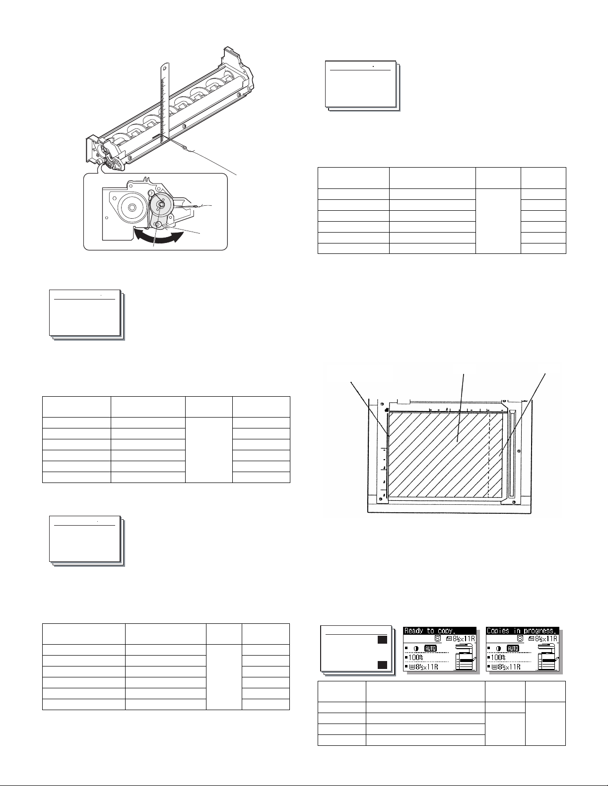
(4) Rear edge void adjustment
1) Set a scale as shown in the figure below.
A4 (8.5" x 11")
Paper rear edge
2) Set the document size to A4 (8.5" x 11"), and make a copy at
100%.
3) If an adjustment is required, follow the procedures below.
Void amount (Standard value: 4mm or less)
10
Example: When setting the lead edge void to 2.5mm:
2.5 /0.127 = about 20
<Adjustment specification>
Adjustment
mode
Main cassette
lead edge void
Print start
position
SIM Set value Spec value
50-1-2B/0.127 Lead edge void:
1 to 4mm
50-5 99 – H/0.127
Image loss: 3mm
or less
Setting
range
1 – 99
(3) SPF image lead edge position adjustment
1) Set a scale on the OC table as shown below.
Note: Since the printed copy is used as a test chart, put the scale in
paralleled with the edge lines.
2) Make a copy, then use the copy output as an original to make an
SPF copy again.
Scale image
Paper rear edge
4) Execute SIM 50-1 and set the density mode to DEN-B. The currently set adjustment value is displayed.
5) Enter the set value and press the start key.
The correction value is stored and a copy is made.
<Adjustment specification>
Adjustment
mode
Rear edge
void
SIM Set value
50-1-6
1 step: 0.127mm
shift
Spec
value
4mm or
less
Setting
range
1 – 99
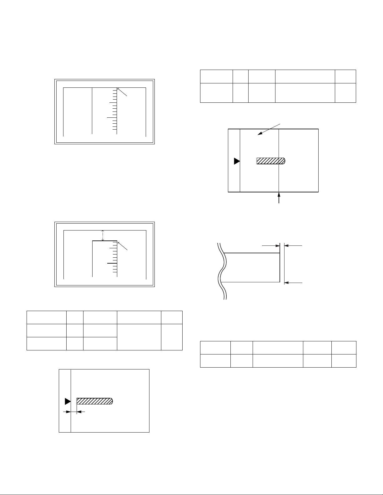
(5) Paper off center adjustment
1) Perform this adjustment after execution of SIM 48-3.
2) Set a test chart (UKOG-0089CSZZ) on the document table.
3) Select a paper feed port and make a copy.
Compare the copy and the test chart. If necessary, perform the following adjustment procedure.
4) Execute SIM 50-10.
Select the mode with the arrow keys, enter the adjustment value
with the 10-key, and press the [OK] key.
Pressing the [START] key makes a print.
Pressing the [RETURN] key returns to the mode selection.
AR-5127 ADJUSTMENTS 7 - 3
(Initial screen) (Input screen) (Executing screen)
Sim50-10 PRT.CENTER
1:BYPASS 50
2:TRAY1 50
3:TRAY2 50
1/2 50
Display
items
1:BYPASS
2:TRAY1
3:TRAY2
4:TRAY3
5:TRAY4
6:DUPLEX
Setup of various copy conditions: Similar to the normal copy mode.
<Adjustment specification>
Adjustment
mode
Paper off
center
Second
print surface
off-center
Manual feed 1-99 50
1st cassette
2nd cassette
3rd cassette
4th cassette
Back print
SIM Set value Spec value
50-10-2Add 1: 0.127mm
50-10
Content
shift to R side.
Reduce 1:
0.127mm shift to L
-6
side.
Setting
range
Single:
Center
±2.0mm
Duplex:
Center
±2.5mm
Default
Setting
range
1 – 99
(6) Left edge void area adjustment
Note: Before performing this adjustment, be sure to check that the
paper off center adjustment (SIM 50-10) is completed.
1) Set a test chart (UKOG-0089CSZZ) on the document table.
2) Select a paper feed port and make two copies.
Compare the second copy and the test chart. If necessary, perform the following adjustment procedure.
∗
The first copy does not show the void. Be sure to check the second
copy.
3) Execute SIM 50-1.
Select the mode with the arrow keys, enter the adjustment value
with the 10-key, and press the [OK] key.
Pressing the [START] key makes a print.
Pressing the [RETURN] key returns to the mode selection.
(Initial screen) (Input screen) (Executing screen)
Sim50-1 LEAD EDGE
1:RRC-A 43
2:RRC-B 18
3:RRC-MANUAL 18
1/4 [ 1- 99] 43
Display items Content
1:RRC-A
2:RRC-B
3:RRC-MANUAL
4:RRC-OPTION
5:RRC-DUPLEX
6:DEN-B
7:DEN-B-DUP
8:SIDE VOID
9:SIDE VOID-DUP
10:LOSS(OC)
Setup of various copy conditions: Similar to the normal copy mode.
<Adjustment specification>
Adjustment
mode
Left edge void 50-1-8 1 step: 0.127mm shift 0.5 – 4mm 1 – 99
Original scan start position adjustment 1-99 43 Tray selection: Made by user.
RRC cancel adjustment (Main cassette) 1-99 18 Tray selection: Main cassette is specified.
RRC cancel adjustment (Manual feed cassette) 1-99 18 Tray selection: Manual feed cassette is specified.
RRC cancel adjustment (Option cassette) 1-99 18 Tray selection: 2nd cassette is specified.
RRC cancel adjustment (back of the machine) 1-99 18 Tray selection: Made by user.
Rear edge void adjustment 1-99 30 Tray selection: Made by user.
Rear edge void adjustment (Duplex) 1-99 50 Tray selection: Made by user.
Left edge void adjustment (First print surface) 1-99 18 Tray selection: Made by user.
Left edge void adjustment (Duplex) 1-99 18 Tray selection: Made by user.
Image loss quantity adjustment 1-5 3 Tray selection: Made by user.
SIM Set value
Spec
value
Setting
range
(7) Main scanning direction (FR direction) distortion
balance adjustment
1) Remove the OC glass and the right cabinet.
1)
1)
1)
2)
Setting
range
Default Remark
2) Loosen the copy lamp unit wire fixing screw.
3)
1)
4)
Wire fixing screw
5)
AR-5127 ADJUSTMENTS 7 - 4
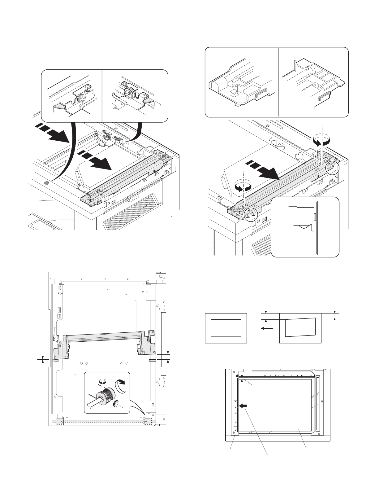
3) Manually turn the mirror base drive pulley and bring No. 2/3 mirror
base unit into contact with the positioning plate.
At that time, if the front frame side and the rear frame side of No. 2/
3 mirror base unit are brought into contact with the positioning
plate at the same time, the mirror base unit parallelism is proper.
If one of them is in contact with the positioning plate, perform the
adjustment of 4).
6) Put No. 2/3 mirror base unit on the positioning plate again, push
the projections on the front frame side and the rear frame side of
the copy lamp unit to the corner frame, and tighten the wire fixing
screw.
4) Loosen the set screw of the scanner drive pulley which is not in
contact with No. 2/3 mirror base unit positioning plate.
5) Without moving the scanner drive pulley shaft, manually turn the
scanner drive pulley until the positioning plate is brought into contact with No. 2/3 mirror base unit, then fix the scanner drive pulley.
(8) Sub scanning direction (scanning direction) distortion
adjustment (Winding pulley position adjustment)
This adjustment must be performed in the following cases:
• When the mirror base drive wire is replaced.
• When the lamp unit, or No. 2/3 mirror holder is replaced.
• When a copy as shown is made.
La
Paper exit
direction
Original Copy
1) Set A3 (11" x 17") white paper on the original table as shown
below.
Place a little clearance from
the rear side original guide.
Lb
AR-5127 ADJUSTMENTS 7 - 5
Glass holding plate
Fit the paper edge and
A3 (11" x 17") white paper
the glass holding plate edge.
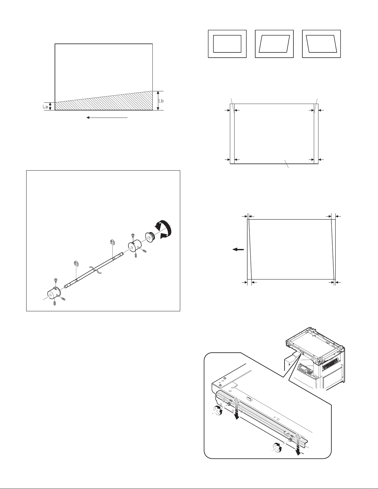
2) Open the original cover and make a normal (100%) copy.
3) Measure the width of the black background at the lead edge and at
the rear edge.
• When a following copy is made.
Original Copy A Copy B
1) Make an original for the adjustment.
Make test sheet by drawing parallel lines at 10mm from the both
ends of A3 (11" x 17") white paper as shown below. (These lines
must be correctly parallel to each other.)
Parallel line Parallel line
Paper exit direction
La: Lead edge black background width
Lb: Rear edge black background width
If the width (La) of the black background at the lead edge is equal
that (Lb) at the rear edge, there is no need to execute the following
procedures of 4) – 7).
4) Loosen the mirror base drive pulley fixing screw on the front frame
side or on the rear frame side.
• When La < Lb
Turn the mirror base drive pulley on the front frame side in the
arrow direction A. (Do not move the mirror base drive pulley shaft.)
• When La > Lb
Turn the mirror base drive pulley on the rear frame side in the
arrow direction A. (Do not move the mirror base drive pulley shaft.)
Rear side
A
B
Front side
10mm
10mm
10mm
10mm
White paper
2) Make a normal (100%) copy of the test sheet on A3 (11" x 17")
paper. (Fit the paper edge and the glass holding plate edge.)
3) Measure the distances (La, Lb, Lc, Ld) at the four corners as
shown below.
La
Lc
Paper exit
direction
Lb Ld
5) Tighten the fixing screw of the mirror base drive pulley.
<Adjustment specification>
La = Lb
6) Execute the main scanning direction (FR) distortion balance
adjustment previously described in 2) again.
(9) Main scanning direction (FR direction) distortion
balance adjustment (Rail height adjustment)
When there is no skew copy in the mirror base scanning direction and
there is no horizontal error (right angle to the scanning direction), the
adjustment can be made by adjusting the No. 2/3 mirror base unit rail
height.
Before performing this adjustment, be sure to perform the horizontal
image distortion adjustment in the laser scanner section.
This adjustment must be performed in the following cases:
• When the mirror base wire is replaced.
• When the copy lamp unit and no. 2/3 mirror unit are replaced.
• When the mirror unit rail is replaced and moved.
AR-5127 ADJUSTMENTS 7 - 6
When La = Lb and Lc = Ld, no need to perform the procedures 4)
and 5).
4) Move the mirror base B rail position up and down (in the arrow
direction) to adjust.
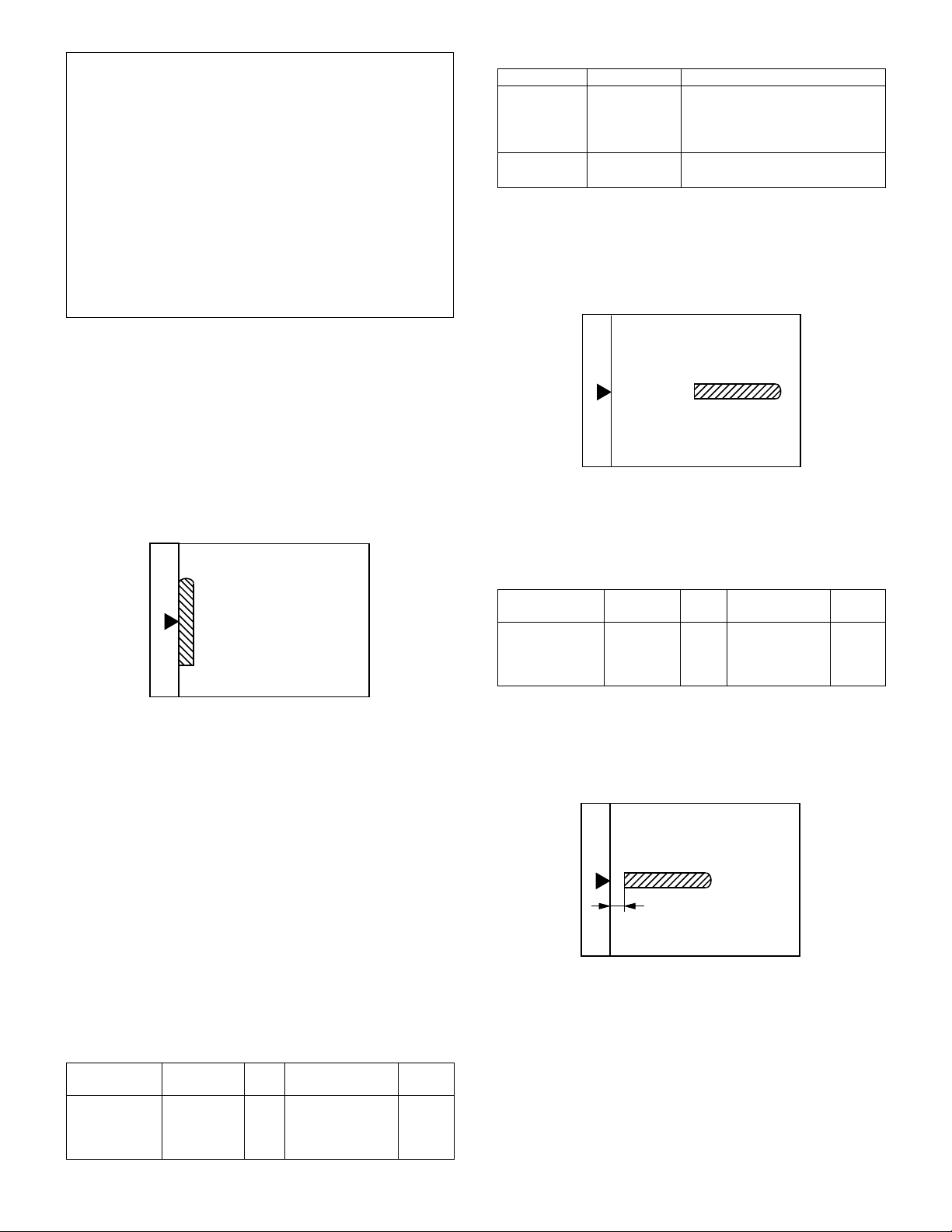
• When La > Lb
Shift the mirror base B rail upward by the half of the difference of
La–Lb.
• When La < Lb
Shift the mirror base B rail downward by the half of the difference
of Lb–La.
Example: When La = 12mm and Lb = 9mm, shift the mirror base
• When Lc >Ld
Shift the mirror base B rail downward by the half of the difference
of Lc–Ld.
• When Lc < Ld
When Lc < Ld, move the mirror base B on the paper feed side
upward.
∗
When moving the mirror base rail, hold the mirror base rail with
your hand.
<Adjustment specification>
La = Lb, Lc = Ld
5) After completion of adjustment, manually turn the mirror base drive
pulley, scan the mirror base A and mirror base B fully, and check
that the mirror bases are not in contact with each other.
∗
If the mirror base rail is moved extremely, the mirror base may be in
contact with the frame or the original glass. Be careful to avoid this.
B rail upward by 1.5mm.
(10) Main scanning direction (FR direction) magnification
ratio adjustment (SIM 48-1)
Note: Before performing this adjustment, be sure to check that the
CCD unit is properly installed.
1) Put a scale on the original table as shown below.
2) Execute SIM 48-1.
3) After warm-up, shading is performed and the current set value of
the main scanning direction magnification ratio is displayed on the
display section in 2 digits.
4) Select the mode and press the start key again.
5) Auto correction mode (SIM48-1-1)
The mirror unit moves to the shading position, and the reference
width of the reference white plate is scanned, and the correction
value is automatically calculated from that scanned value.
The correction value is displayed and a copy is made.
6) Compare the scale image and the actual scale.
If a fine adjustment is required, switch to the manual correction
mode with the magnification ratio display key and perform fine
adjustment.
7) Manual correction mode (SIM48-1-2)
Enter the set value and press the start key.
The correction value is stored and a copy is made.
<Adjustment specification>
Note: A judgement must be made with 200mm width, and must not be
made with 100mm width.
Adjustment
mode
Main scanning
direction
magnification
ratio
Spec value SIM Set value
At normal:
±1.0%
48-1 Add 1: 0.1%
increase
Reduce 1: 0.1%
decrease
Setting
range
1 – 99
• Error in the auto correction mode
Display Content Major cause
Copy quantity
display "– –"
Paper jam
lamp ON
The correction
value
calculated is
over 5%.
Reference line
scanning error
• Improper position of reference
width line of the reference white
plate
• Improper installation of CCD unit
• Defective CCD
• No reference white plate
(11) Sub scanning direction (scanning direction)
magnification ratio adjustment (SIM 48-1-3)
a. OC mode in copying
Note: Execute the procedure after completion of SIM 48-1-3.
1) Put a scale on the original table as shown below, and make a normal (100%) copy.
2) Compare the scale image and the actual scale.
If necessary, perform the following adjustment procedures.
3) Execute SIM 48-1-3.
4) Enter the set value and press the start key.
The set value is stored and a copy is made.
<Adjustment specification>
Adjustment
mode
Sub scanning
direction
magnification
ratio (OC mode)
b. RSPF sub scanning direction magnification ratio
Note: Before performing this adjustment, be sure to check that the
CCD unit is properly installed and that OC mode adjustment in
copying has been completed.
1) Put a scale on the original table as shown below, and make a normal (100%) copy to make a test chart.
Note: Since the printed copy is used as a test chart, put the scale in
paralled with the edge lines.
2) Set the test chart on the SPF and make a normal (100%) copy.
3) Compare the scale image and the actual image.
If necessary, perform the following adjustment procedures.
4) Execute SIM 48-1-4.
5) After warm-up, shading is performed.
The current front surface sub scanning direction magnification ratio
correction value is displayed in two digits on the display section.
Spec value SIM Set value
At normal:
±1.0%
48-1-3Add 1:
0.05% increase
Reduce 1:
0.05% decrease
Setting
range
1 – 99
AR-5127 ADJUSTMENTS 7 - 7
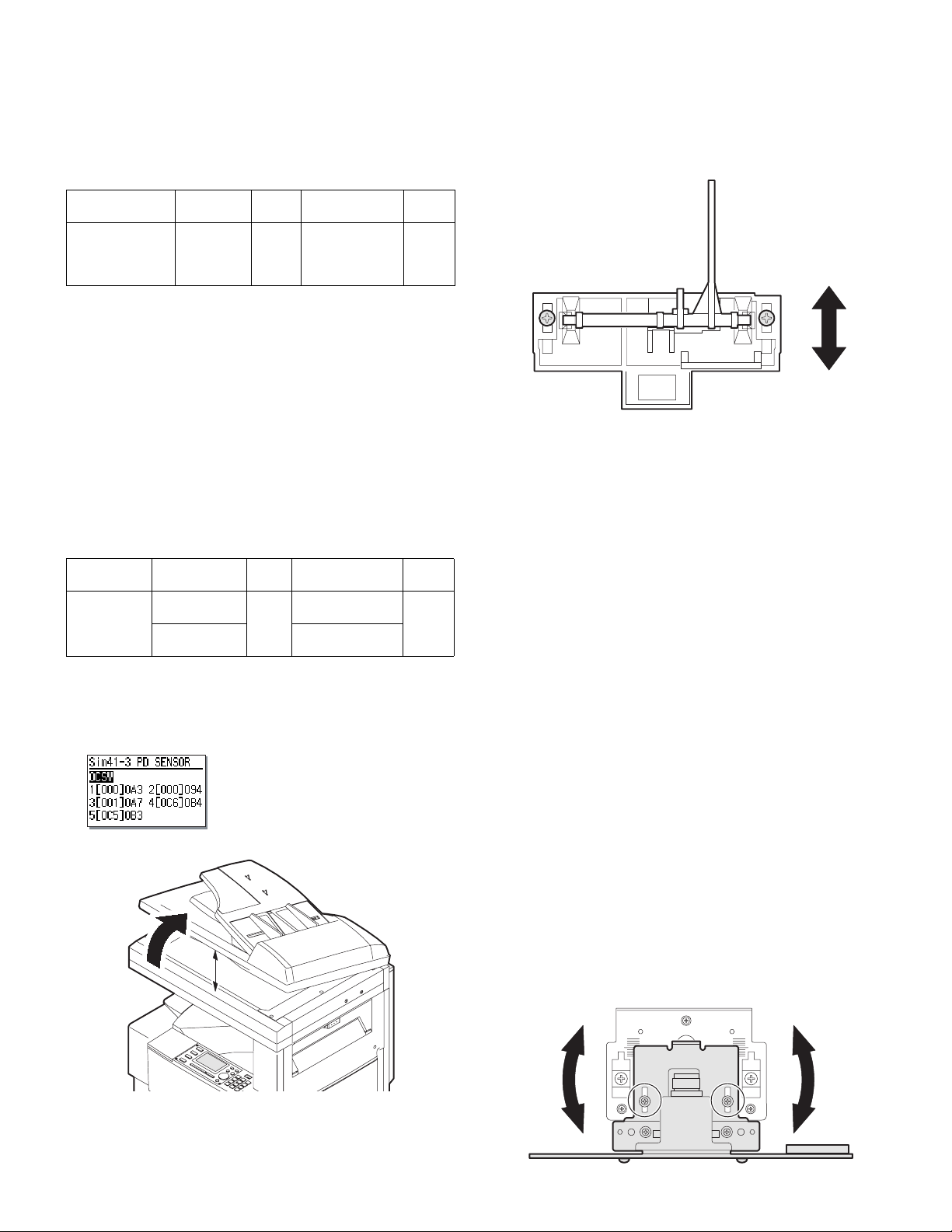
6) Enter the set value and press the start key.
The set value is stored and a copy is made.
7) Execute SIM 48-1-5.
The current back surface sub scanning direction magnification
ratio is displayed in two digits on the display section.
8) Enter the set value and press the start key.
The set value is stored and a copy is made.
<Adjustment specification>
Adjustment
mode
Sub scanning
direction
magnification
ratio (SPF mode)
Spec value SIM Set value
At normal:
±1.0%
48-1-4
48-1-5
Add 1:
0.05% increase
Reduce 1:
0.05% decrease
Setting
range
1 – 99
(12) Off center adjustment (SPF mode)
Note: Before performing this adjustment, be sure to check that the
paper off center is properly adjusted.
1) Place the center position adjustment test chart (sheet with a
straight line in the scan direction at the center) on the SPF.
2) Make a normal copy from the manual paper feed tray, and check
the printed copy with the test chart.
If any adjustment is required, perform the following procedure.
3) Execute SIM 50-12.
4) After warm-up, shading is performed and the current set value of
the off center adjustment is displayed on the display section in 2
digits.
5) Enter the set value and press the start key.
The set value is stored and a copy is made.
<Adjustment specification>
Adjustment
mode
Original off
center mode
(SPF mode)
Spec value SIM Set value
Single: Center
± 3.0mm
Duplex: Center
±3.5mm
50-12 Add 1: 0.1mm
shift to R side
Reduce 1: 0.1mm
shift to L side
Setting
range
1 – 99
(13) OC (SPF) open/close detection position adjustment
1) Execute SIM 41-3.
2) Gradually close the OC (SPF) from the full open position, and measure distance A when the display on the operation panel changes.
(See the figure below.)
Distance A = Table glass top - OC (SPF) handle rib
A
<Adjustment specification>
OC (SPF) open/close position A: 125 – 225mm
3) If the distance is outside the specified range, adjust the open/close
sensor attachment plate position as shown below.
・ Distance < 125mm : Shift toward A.
・ Distance > 22 5mm : Shift toward B.
A
B
(14) Original sensor adjustment (SIM 41-2, 41-4)
1) Set A3 (11" x 17") paper on the OC table.
(Keep the SPF (OC cover) open.)
2) Execute SIM 41-2.
3) Keep A=125mm, and execute SIM 41-4. (Do not put paper on the
table.)
4) Check the reaction with SIM 41-1.
(15) SPF white correction pixel position adjustment
(required in an SPF model when replacing the lens
unit) (SIM63-7)
1) Fully open the SPF.
2) Execute SIM 63-7.
3) When the operation panel displays "COMPLETE," the adjustment
is completed.
4) If the operation panel displays "ERROR," perform the following
measures.
• When the display is 0:
Check that the SPF is open.
Check that the lamp is ON. (If the lamp is OFF, check the MCU connector.)
Check that the CCD harness is properly inserted into the MCU connector.
• When the display is 281 or above:
1) Remove the table glass.
2) Remove the dark box.
3) Slide the lens unit toward the front side and attach it, then execute SIM.
• When the display is 143 or below:
1) Remove the table glass.
2) Remove the dark box.
3) Slide the lens unit toward the rear side and attach it, then execute SIM.
F
R
AR-5127 ADJUSTMENTS 7 - 8
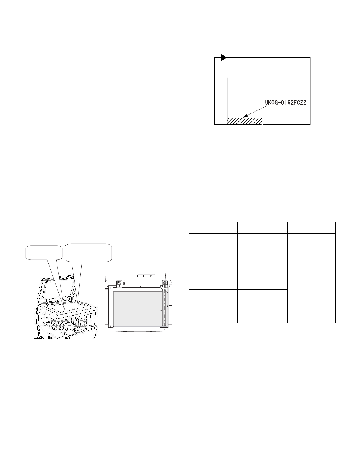
∗
When the lens unit is moved, execute the OC main scanning magnification ratio auto adjustment, SIM 48-1-1, SIM48-3 and the SPF
original off-center adjustment.
∗
This adjustment is basically O.K. with SIM 63-7.
(16) SPF scan position auto adjustment
[Function]
Used to adjust the SPF scan position automatically.
[Operation]
1) With the SPF or the OC cover open, place a chart of black background on the OC glass. (In the SPF standard model, the SPF
glass surface is included.)
∗
Use a black chart (UKOG-0011QSZZ) or prepare a chart as shown
below.
Chart size: 310 x 470, prepared with cutting sheet No. 791 (Black) or
an equivalent one.
Reason: To prevent erroneous detection by disturbing light of a fluo-
2) Enter SIM53-08, and press [START] button.
<Note>
• After completion of the SPF scan position auto adjustment, the SPF
lead edge adjustment must be executed. (Both surfaces)
• There must be no other sheet than the black chart on the glass sur-
face.
• Especially when in SPF scan, the center area is scanned in the main
scan direction. Be careful to prevent external light from entering the
scan area.
3) Check that the lead edge is not shifted. (Both surfaces)
Place only the black
chart on the OC glass.
rescent lamp, etc.
Outline of SIM: The optical unit is shifted to recognize the boundary between the OC glass and the SPF glass cover.
With the same position as the reference, the SPF scan position is
automatically adjusted.
(If the original lead edge adjustment has been made properly, even
when the scan position is shifted, it is followed automatically.)
For the SPF standard-provision
machine, check that the black
chart covers the SPF glass.
Placing the black chart
The black chart must cover
this area.
C. Image density (exposure) adjustment
(1) Copy mode (SIM46-2)
1) Set a test chart (UKOG-0162FCZZ) on the OC table as shown
below.
Rear
Front
2) Place three or more sheets of A3 (11" x 17") paper on the test
chart.
3) Execute SIM 46-2.
4) After warm-up, shading is performed and the current set value of
the density (exposure) level is displayed on the display section in 2
digits.
For mode selection, use the [10-key].
5) Change the set value with the [10-key] to adjust the copy image
density.
6) Make a copy and check that the specification below is satisfied.
Note: Place originals in the rear reference, and the test chart in the
front reference when adjusting the exposure.
<Adjustment specification>
Density
mode
AUTO AUTO
TEXT TEXT
TEXT/
PHOTO
PHOTO PHOTO
SUPER
PHOTO
TONER
SAVE
Display
Lamp
TEXT/
PHOTO
SUPER
PHOTO
AUTO (TS)
TEXT (TS)
TEXT
PHOTO (TS)
Exposure
level
–
3
3
3
3 Disabled
3
3
3
Sharp Gray
Chart output
"3" is
copied.
"3" is
copied.
"3" is
copied.
"3" is
copied.
"3" is
copied.
"3" is
copied.
"3" is
copied.
Set value
If too bright,
increase the
quantity
displayed on
the copy
quantity
display.
If too dark,
decrease the
quantity
displayed on
the copy
quantity
display.
Setting
range
0 – 99
4) Change the adjustment value of the SPF scan end position.
(Change the adjustment value of SIM50-6-3 from 50 to 36.)
Change the number of steps for Pin off – scan end position from
1,014 to 986.
Be sure to execute this adjustment because an image may be cut
off during FAX transmission though copying is normally performed.
5) Change the initial value of the SPF exposure adjustment (SIM46-
20) from 50 to 53.
(For the CCD exposure adjustment with SPF, use the value of the
OC adjustment value +3.)
There are suffixes of –1 SPF and –2 SPF. Change each of them.
AR-5127 ADJUSTMENTS 7 - 9
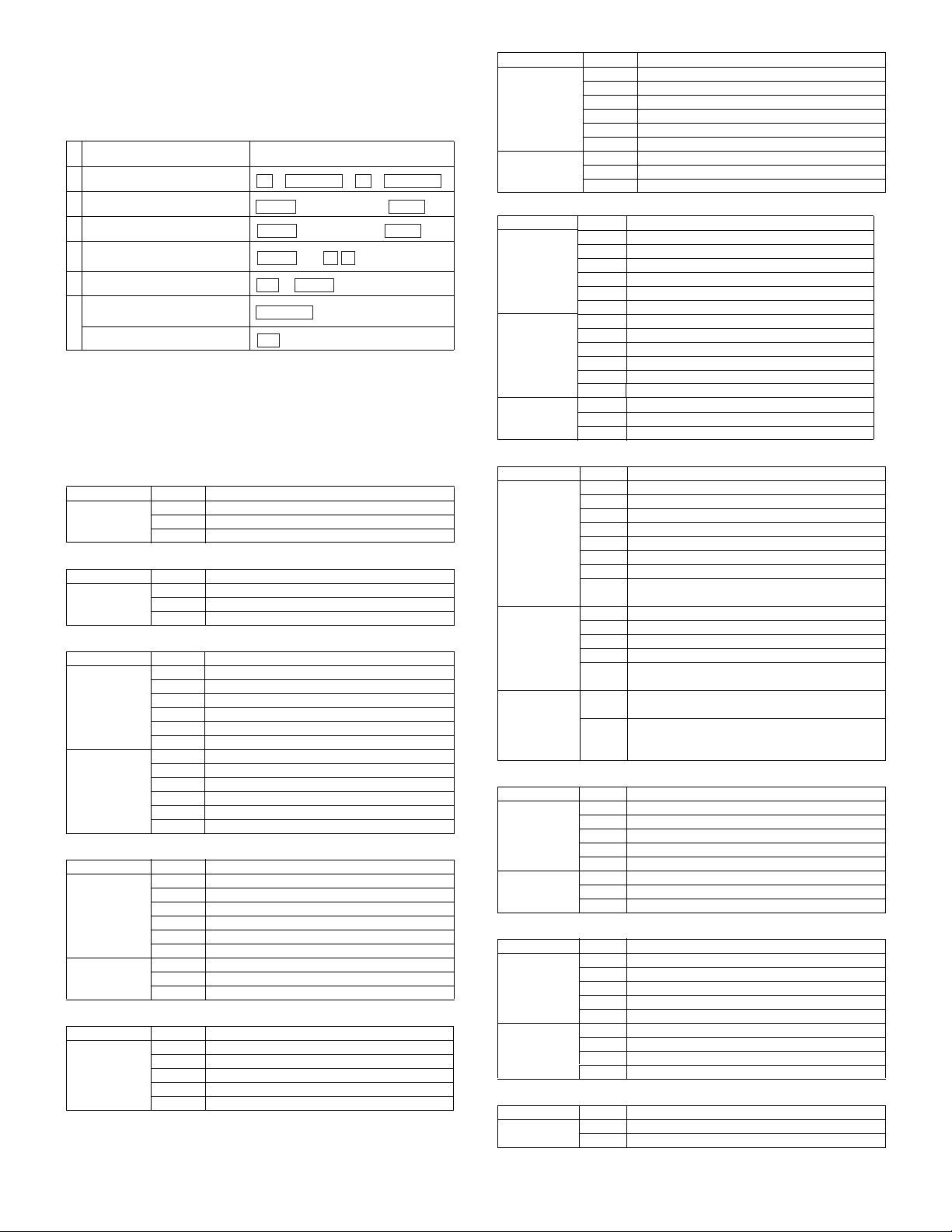
[8] SIMULATION
1. Operating procedures and operations
A. Basic operation
Procedure Key operation
1 Simulation mode selection
2 Main code selection
3 Sub code selection
Selection of the mode and
4
item
5 Start simulation operation
Returns to the sub code
selection.
6
Simulation mode clear
• Selection of the main code and the sub code is set with the [START]
key.
• There are two or more screens, the adjustment "Current page/Max.
page" is displayed. Press [
↑
a screen.
B. Simulation kinds and valid key functions
Data screen system
Screen Key Function
Counter display CA Cancel simulation
Sensor check system
Screen Key Function
Sensor check
screen
Data setting system
Screen Key Function
Selection of the
adjustment
items
Adjustment
value input
Load operation system
Screen Key Function
Load selection CA Cancel simulation
Execution CA Cancel simulation
Load operation system with magnification ratio setup
Screen Key Function
Selection of the
number of times
Interrupt Sub code input screen appears.
↓, ↑ Page switch (in the case of multiple pages)
CA Cancel simulation
Interrupt Sub code input screen appears.
↓, ↑ Page switch (in the case of multiple pages)
CA Cancel simulation
Interrupt Sub code input screen appears.
C Input value clear
10-key Adjustment item selection
↓, ↑ Page switch (in the case of multiple pages)
OK The adjustment value input screen appears.
CA Cancel simulation
Interrupt The sub code input screen appears.
10-key Adjustment value input
C Input value clear
OK Input final value
Back The adjustment item select screen appears.
Interrupt Sub code input screen appears.
C Input value clear
10-key Load number selection
↓, ↑ Page switch (in the case of multiple pages)
OK Shifts to the screen during operation.
Interrupt Sub code input screen appears.
Back The load selection screen appears.
CA Simulation cancel
Interrupt Sub code input screen appears.
C Input value clear
10-key Entry of the number of times
OK Shifts to the magnification ration selection screen.
→
INTERRUPT
#
10-key
10-key
10-key
START
OK
or
INTERRUPT
CA
→ →
C
(Input main code)
(Input sub code)
and
↑ ↓
INTERRUPT
→
START
→
START
] key (previous page) or [↓] key to select
Screen Key Function
Maginification
ratio selection
Execution CA Cancel simulation
CA Cancel simulation
Interrupt Sub code input screen appears.
←, → Magnification ratio selection (1% increment)
↓, ↑ Fixed magnification ratio setting
OK Shifts to the screen during operation.
Back Shifts to the number of times selection screen.
Interrupt Sub code input screen appears.
Back Shifts to the magnification ratio setup menu.
Load operation system with data setup
Screen Key Function
Selection of
the adjustment
items
Adjustment
value input
Execution CA Cancel simulation
CA Cancel simulation
Interrupt Sub code input screen appears.
C Input value clear
10-key Adjustment item selection
↓, ↑ Page switch (in the case of multiple pages)
OK The adjustment value input screen appears.
CA Cancel simulation
Interrupt Sub code input screen appears.
10-key Adjustment value input
C Input value clear
OK Set value check
Back The adjustment item selection screen appears.
Interrupt Sub code input screen appears.
Back The adjustment value input screen appears.
Single print system
Screen Key Function
Selection of the
adjustment
items
Adjustment
value input
Execution CA After the single print, the copy conditions are cleared
CA Cancel simulation
Interrupt Sub code input screen appears.
C Input value clear
10-key Adjustment value input
↓, ↑ Page switch (in the case of multiple pages)
←, → Item switch
OK The adjustment value input screen appears.
START Input value assured. → Print one page. → Shifts to
the execution screen.
CA Cancel simulation
C Input value clear
Back The adjustment item selection screen appears.
10-key Adjustment value input
START Determination of the input value → Print of one page
→ shift to the execution screen.
and the adjustment value input screen appears.
C After the single print, the copy conditions are not
cleared and the adjustment value input screen
appears.
Load operation system with data display
Screen Key Function
Initial stage CA Cancel simulation
Execution CA Cancel simulation
Interrupt Sub code input screen appears.
C Input value clear
10-key Speed number selection
OK Shifts to the screen during operation.
Interrupt Sub code input screen appears.
Back The intial screen appears.
Memory clear system
Screen Key Function
Counter
selection
Check CA Cancel simulation
CA Cancel simulation
Interrupt Sub code input screen appears.
C Input value clear
10-key Load number selection
OK The check screen appears.
Interrupt Sub code input screen appears.
OK Clears and shifts to the counter select menu.
Back Not clears and shifts to the counter select menu.
Display check system
Screen Key Function
Display check CA Cancel simulation
Interrupt Sub code input screen appears.
AR-5127 SIMULATION 8 - 1
 Loading...