


CD-C606/1900,CP-C606/1900
SERVICE MANUAL
No. S3909CDC606//
Illustration: CD-C606
CD-C606
CD-C1900
CP-C606
CP-C1900
CD-C606 mini component system consisting of CD-C606 mini component system and CP-C606 speaker system
CD-C1900 mini component system consisting of CD-C1900 mini component system and CP-C1900 speaker system
• In the interests of user-safety the set should be restored to its original condition and only parts identical to those specified be used.
CONTENTS |
|
|
Page |
IMPORTANT SERVICE NOTES (FOR U.S.A. ONLY) ....................................................................................................... |
2 |
SPECIFICATIONS ............................................................................................................................................................. |
2 |
NAMES OF PARTS ........................................................................................................................................................... |
3 |
OPERATION MANUAL ...................................................................................................................................................... |
5 |
QUICK GUIDE ................................................................................................................................................................... |
6 |
DISASSEMBLY .................................................................................................................................................................. |
8 |
REMOVING AND REINSTALLING THE MAIN PARTS ................................................................................................... |
10 |
ADJUSTMENT ................................................................................................................................................................. |
11 |
NOTES ON SCHEMATIC DIAGRAM .............................................................................................................................. |
13 |
TYPE OF TRANSISTER AND LED ................................................................................................................................. |
13 |
WAVEFORMS OF CD CIRCUIT ...................................................................................................................................... |
14 |
BLOCK DIAGRAM ........................................................................................................................................................... |
15 |
SCHEMATIC DIAGRAM / WIRING SIDE OF P.W.BOARD .............................................................................................. |
18 |
VOLTAGE ........................................................................................................................................................................ |
32 |
TROUBLESHOOTING ..................................................................................................................................................... |
33 |
FUNCTION TABLE OF IC ................................................................................................................................................ |
37 |
FL SEGMENT ................................................................................................................................................................... |
42 |
PARTS GUIDE/EXPLODED VIEW |
|
PACKING OF THE SET (FOR U.S.A. ONLY) |
|
SHARP CORPORATION |
This document has been published to be used |
for after sales service only. |
|
– 1 – |
The contents are subject to change without notice. |
|
CD-C606/1900,CP-C606/1900
FOR A COMPLETE DESCRIPTION OF THE OPERATION OF THIS UNIT, PLEASE REFER TO THE OPERATION MANUAL.
IMPORTANT SERVICE NOTES (FOR U.S.A. ONLY)
BEFORE RETURNING THE AUDIO PRODUCT
(Fire & Shock Hazard)
Before returning the audio product to the user, perform the following safety checks.
1.Inspect all lead dress to make certain that leads are not pinched or that hardware is not lodged between the chassis and other metal parts in the audio product.
2.Inspect all protective devices such as insulating materials, cabinet, terminal board, adjustment and compartment covers or shields, mechanical insulators etc.
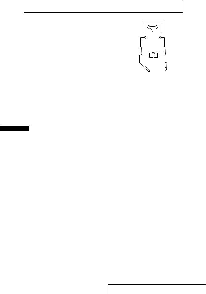
3.To be sure that no shock hazard exists, check for leakage current in the following manner.
*Plug the AC line cord directly into a 120 volt AC outlet.
*Using two clip leads, connect a 1.5k ohm, 10 watt resistor paralleled by a 0.15μF capacitor in series with all exposed metal cabinet parts and a known earth ground, such as conduit or electrical ground connected to earth ground.
*Use a VTVM or VOM with 1000 ohm per volt, or higher, sensitivity to measure the AC voltage drop across the resistor (See diagram).
VTVM
|
AC SCALE |
|
|
1.5k ohms |
|
|
10W |
|
|
0.15 F |
|
|
TEST PROBE |
CONNECT TO |
|
KNOWN EARTH |
|
TO EXPOSED |
|
|
|
GROUND |
|
METAL PARTS |
|
|
|
|
* Connect the resistor connection to all exposed metal parts having a return path to the chassis (antenna, metal cabinet, screw heads, knobs and control shafts, escutcheon, etc.) and measure the AC voltage drop across the resistor.
All check must be repeated with the AC line cord plug connection reversed.
Any reading of 0.3 volt RMS (this corresponds to 0.2 milliamp. AC.) or more is excessive and indicates a potential shock hazard which must be corrected before returning the audio product to the owner.
SPECIFICATIONS
CD-C606/1900
● General
Power source: |
AC 120 V, 60 Hz |
Power consumption: Stand-by; 0.3 W |
|
|
Power on; 40 W |
Dimensions: |
Width; 10-5/8" (270 mm) |
(For U.S.A.) |
Height; 11-13/16" (300 mm) |
|
Depth; 13-7/8" (353 mm) |
Dimensions: |
Width; 270 mm (10-5/8") |
(For Canada) |
Height; 300 mm (11-13/16") |
|
Depth; 353 mm (13-7/8") |
Weight: |
10.3 lbs (4.7 kg) |
(For U.S.A.) |
|
Weight: |
4.7 kg (10.3 lbs) |
(For Canada) |
|
● Amplifier section
Output power: |
10 watts minimum RMS per |
(For U.S.A.) |
channel into 8 ohms from 80 Hz to |
|
20 kHz, 10% total harmonic |
|
distortion |
Output power: |
MPO; 36 W (18 W + 18 W) |
(For Canada) |
(10% T.H.D.) |
|
RMS; 20 W (10 W + 10 W) |
|
(10% T.H.D.) |
Output terminals: |
Speakers; 8 ohms |
|
Headphones; 16-50 ohms |
|
(recommended; 32 ohms) |
●Tuner section |
|
Frequency range: |
FM; 87.5-108 MHz |
|
AM; 530-1,720 kHz |
● Cassette deck section
Frequency response: 50-14,000 Hz (Normal tape)
Signal/noise ratio:
Wow and flutter:
● Compact disc player section
Type: |
3-disc multi-play compact disc player |
||
Signal readout: |
Non-contact, 3-beam semiconductor |
||
|
|
|
laser pickup |
D/A converter: |
1-bit D/A converter |
||
Frequency response: 20 -20,000 Hz |
|||
Dynamic range: |
90 dB (1 kHz) |
||
|
|
|
|
|
CP-C606/1900 |
|
|
● Speaker section |
|
||
Type: |
2-way [4” (10cm) woofer and |
||
|
|
|
super tweeter] |
Maximum input |
|
||
power: |
20 W |
||
Rated input power: |
10 W |
||
Impedance: |
8 ohms |
||
Dimensions: |
Width; 8-11/16" (220 mm) |
||
(For U.S.A.) |
Height; 11-13/16" (300 mm) |
||
|
|
|
Depth; 7-1/16" (180 mm) |
Dimensions: |
Width; 220 mm (8-11/16") |
||
(For Canada) |
Height; 300 mm (11-13/16") |
||
|
|
|
Depth; 180 mm (7-1/16") |
Weight:(For U.S.A.) |
4.4 lbs. (2.0 kg)/each |
||
Weight:(For Canada) 2.0 kg (4.4 lbs.)/each
Specifications for this model are subject to change without prior notice.
– 2 –

CD-C606/1900,CP-C606/1900
FOR A COMPLETE DESCRIPTION OF THE OPERATION OF THIS UNIT, PLEASE REFER TO THE OPERATION MANUAL.
IMPORTANT SERVICE NOTES (FOR U.S.A. ONLY)
BEFORE RETURNING THE AUDIO PRODUCT
(Fire & Shock Hazard)
Before returning the audio product to the user, perform the following safety checks.
1.Inspect all lead dress to make certain that leads are not pinched or that hardware is not lodged between the chassis and other metal parts in the audio product.
2.Inspect all protective devices such as insulating materials, cabinet, terminal board, adjustment and compartment covers or shields, mechanical insulators etc.
3.To be sure that no shock hazard exists, check for leakage current in the following manner.
*Plug the AC line cord directly into a 120 volt AC outlet.
*Using two clip leads, connect a 1.5k ohm, 10 watt resistor paralleled by a 0.15μF capacitor in series with all exposed metal cabinet parts and a known earth ground, such as conduit or electrical ground connected to earth ground.
*Use a VTVM or VOM with 1000 ohm per volt, or higher, sensitivity to measure the AC voltage drop across the resistor (See diagram).
VTVM
|
AC SCALE |
|
|
1.5k ohms |
|
|
10W |
|
|
0.15 F |
|
|
TEST PROBE |
CONNECT TO |
|
KNOWN EARTH |
|
TO EXPOSED |
|
|
|
GROUND |
|
METAL PARTS |
|
|
|
|
* Connect the resistor connection to all exposed metal parts having a return path to the chassis (antenna, metal cabinet, screw heads, knobs and control shafts, escutcheon, etc.) and measure the AC voltage drop across the resistor.
All check must be repeated with the AC line cord plug connection reversed.
Any reading of 0.3 volt RMS (this corresponds to 0.2 milliamp. AC.) or more is excessive and indicates a potential shock hazard which must be corrected before returning the audio product to the owner.
SPECIFICATIONS
CD-C606/1900
● General
Power source: |
AC 120 V, 60 Hz |
Power consumption: Stand-by; 0.3 W |
|
|
Power on; 40 W |
Dimensions: |
Width; 10-5/8" (270 mm) |
(For U.S.A.) |
Height; 11-13/16" (300 mm) |
|
Depth; 13-7/8" (353 mm) |
Dimensions: |
Width; 270 mm (10-5/8") |
(For Canada) |
Height; 300 mm (11-13/16") |
|
Depth; 353 mm (13-7/8") |
Weight: |
10.3 lbs (4.7 kg) |
(For U.S.A.) |
|
Weight: |
4.7 kg (10.3 lbs) |
(For Canada) |
|
● Amplifier section
Output power: |
10 watts minimum RMS per |
(For U.S.A.) |
channel into 8 ohms from 80 Hz to |
|
20 kHz, 10% total harmonic |
|
distortion |
Output power: |
MPO; 36 W (18 W + 18 W) |
(For Canada) |
(10% T.H.D.) |
|
RMS; 20 W (10 W + 10 W) |
|
(10% T.H.D.) |
Output terminals: |
Speakers; 8 ohms |
|
Headphones; 16-50 ohms |
|
(recommended; 32 ohms) |
●Tuner section |
|
Frequency range: |
FM; 87.5-108 MHz |
|
AM; 530-1,720 kHz |
● Cassette deck section
Frequency response: 50-14,000 Hz (Normal tape)
Signal/noise ratio:
Wow and flutter:
● Compact disc player section
Type: |
3-disc multi-play compact disc player |
||
Signal readout: |
Non-contact, 3-beam semiconductor |
||
|
|
|
laser pickup |
D/A converter: |
1-bit D/A converter |
||
Frequency response: 20 -20,000 Hz |
|||
Dynamic range: |
90 dB (1 kHz) |
||
|
|
|
|
|
CP-C606/1900 |
|
|
● Speaker section |
|
||
Type: |
2-way [4” (10cm) woofer and |
||
|
|
|
super tweeter] |
Maximum input |
|
||
power: |
20 W |
||
Rated input power: |
10 W |
||
Impedance: |
8 ohms |
||
Dimensions: |
Width; 8-11/16" (220 mm) |
||
(For U.S.A.) |
Height; 11-13/16" (300 mm) |
||
|
|
|
Depth; 7-1/16" (180 mm) |
Dimensions: |
Width; 220 mm (8-11/16") |
||
(For Canada) |
Height; 300 mm (11-13/16") |
||
|
|
|
Depth; 180 mm (7-1/16") |
Weight:(For U.S.A.) |
4.4 lbs. (2.0 kg)/each |
||
Weight:(For Canada) 2.0 kg (4.4 lbs.)/each
Specifications for this model are subject to change without prior notice.
– 2 –
CD-C606/1900,CP-C606/1900
CD-C606/1900
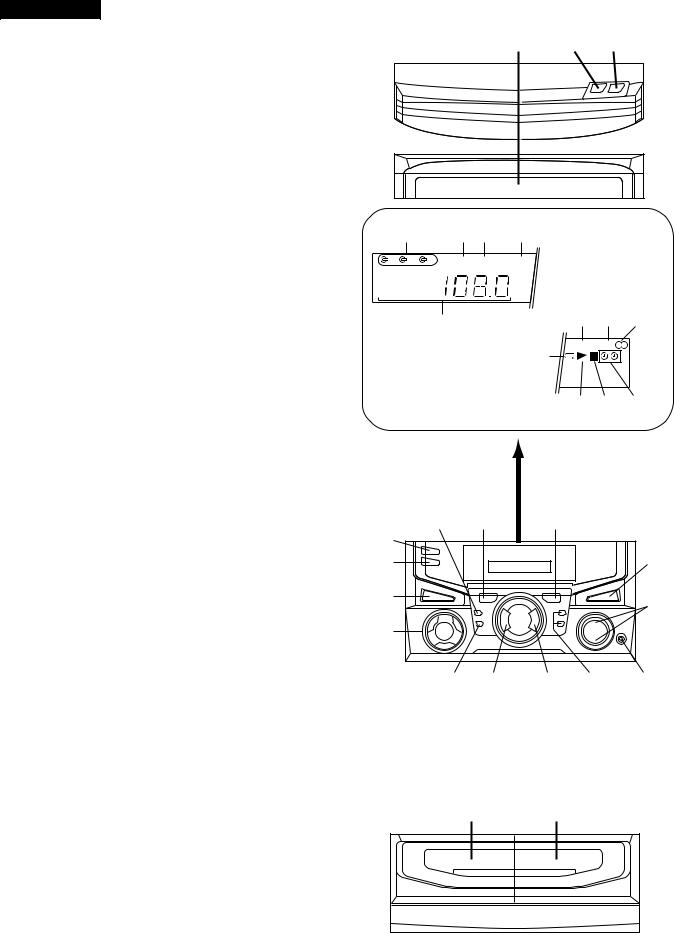
■Front panel
1.Disc Tray
2.Disc Skip Button
3.Open/Close Button
NAMES OF PARTS
1 2 3
4.Disc Number Indicator
5.Record Indicator
6.Sleep Indicator
7.Extra Bass Indicator
8.Function/CD Track/CD Counter/Frequency/ Preset Channel/Volume/Timer/Sleep Time Indicator
9.Memory Indicator
10.FM Stereo Mode Indicator
11.FM Stereo Indicator
12.CD Repeat Indicator
13.CD Play Indicator
14.CD Pause Indicator
15.Timer Indicators
16.(TAPE 2) Record Pause Button
17.(CD) Track Down/Review Button (TUNER) Preset Down Button (TAPE 2) Rewind Button
18.(CD) Track Up/Cue Button (TUNER) Preset Up Button (TAPE 2) Fast Foward Button
19.Timer/Sleep Button
20.Clock Button
21.Power Button
22.Function Selector Buttons
23.Extra Bass/Demo Button
24.Volume Up/Down Buttons
25.Memory/Set Button
26.(CD/TAPE) Stop Button
27.(CD) Play/Repeat Button (TAPE) Play Button
28.Tuning and Time Up/Down Buttons
29.Headphone Socket
30.(TAPE 1) Cassette Compartment
31.(TAPE 2) Cassette Compartment
4 |
5 6 |
7 |
1 |
REC SLEEP |
X-BASS |
8 |
|
9 10 11 |
|
|
|
|
12 |
MEMORY ST |
|
|
|
|
|
kHz |
|
|
MHz |
|
|
13 14 15 |
16 |
17 |
18 |
|
|
19 |
|
|
|
|
20 |
|
|
|
23 |
21 |
|
|
|
24 |
22 |
|
|
|
|
|
|
|
|
|
25 |
26 |
27 |
28 |
29 |
30 |
31 |
– 3 –
CD-C606/1900,CP-C606/1900
CD-C606/1900
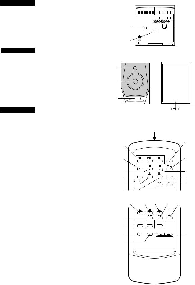
■Rear panel
1.AC Power Input Socket
2.Speaker Terminals
3.FM/AM Loop Aerial Socket
CP-C606/1900
■Speaker
4.Super Tweeter
5.Woofer
6.Bass Reflex Duct
7.Speaker Wire
CD-C606/1900
■Remote control
1.Remote Control Transmitter LED
●CD control section
2.Disc Number Select Buttons
3.Memory Button
4.Pause Button
5.Clear Button
6.Track Down/Review Button
7.Track Up/Cue Button
8.Disc Skip Button
9.Play/Repeat Button
10.Stop Button
11.Random Button
●Tuner control section
12.Preset Up/Down Buttons
1  3
3
2
4
5
6
7
|
1 |
|
2 |
|
8 |
|
|
|
3 |
|
9 |
4 |
|
10 |
5 |
|
11 |
6 |
|
12 |
7 |
|
|
13 |
14 15 |
16 17 |
●Tape control section
13.(TAPE 1) Play Button
14.(TAPE 1/2) Stop Button
15.(TAPE 2) Play Button
16.(TAPE 2) Rewind Button
17.(TAPE 2) Fast Forward Button
18.(TAPE 2) Record Pause Button
19.Function Selector Buttons
20.Power Button
21.Extra Bass Button
22.Volume Up/Down Buttons
18
19
20
21
1 |
22
– 4 –
– 5 –
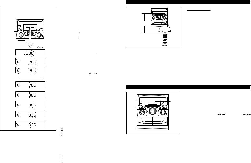
SETTING THE CLOCK |
|
PREPARATION FOR USE |
(Main unit operation)
In this example, the clock is set for the 12-hour (AM 12:00) system.
CLOCK
POWER
MEMORY/ |
TUNING/ |
||
SET |
|||
TIME |
) |
||
|
( |
||
2
3
4
AM 12:00
 AM 0:00
 0:00
0:00
5
6
7
8
9
1 Press the POWER button to enter the stand-by mode.
2 Press the CLOCK button.
3 Within 5 seconds, press the MEMORY/SET button.
4 Press the TUNING/TIME (  or
or ) button to select the time
display mode. |
|
|
|||
"AM 12:00" |
|
|
|
The 12-hour display will appear. |
|
|
|
||||
|
|
|
|
|
(AM 12:00 - PM 11:59) |
"AM 0:00" |
|
|
The 12-hour display will appear. |
||
|
|
||||
|
|
|
|
|
(AM 0:00 - PM 11:59) |
"0:00" |
|
|
|
|
The 24-hour display will appear. |
|
|
|
|
||
|
|
|
|
(0:00 - 23:59) |
|
 Note that this can only be set when the unit is first installed or it has been reset (see page 13).
5 Press the MEMORY/SET button.
6 Press the TUNING/TIME ( or ) button to adjust the hour.
 Press the TUNING/TIME (
 or
or  ) button once to advance the time by 1 hour. Hold it down to advance continuously.
 When the 12-hour display is selected, "AM" will change automatically to "PM".
7 Press the MEMORY/SET button.
8 Press the TUNING/TIME ( or ) button to adjust the minutes.
 Press the TUNING/TIME (
 or
or  ) button once to advance the time by 1 minute. Hold it down to change the time in 5 minute intervals.
 The hour setting will not advance even if minutes advance from "59" to "00".
9 Press the MEMORY/SET button.
 The clock starts operating from "0" seconds. (Seconds are not displayed.)
Note:
 In the event of power failure or when the AC power cord is disconnected, the clock display will go out.
When the AC power supply is restored, the clock display will flash on and off to indicate the time when the power failure occurred or when the AC power cord was disconnected.
If this happens, follow the procedure below to change the clock time.
To change the clock time:
1Press the CLOCK button.
2Within 5 seconds, press the MEMORY/SET button.
3Perform steps 6 - 9 above.
To see the time display:
Press the CLOCK button.
 The time display will appear for about 5 seconds.
To change the time display mode:
1Perform steps 1 - 2 in the section "RESETTING THE MICRO COMPUTER".
2Perform steps 1 - 9 above.
8" - 20' |
|
(0.2 m - 6 m) |
|
15 |
15 |
|
RESETTING THE MICROCOMPUTER
2 |
1,2 |
■ Remote control
Notes concerning use:
●Replace the batteries if the operating distance is reduced or if the operation becomes erratic.
●Periodically clean the transmitter LED on the remote control and the sensor on the main unit with a soft cloth.
●Exposing the sensor on the main unit to strong light may interfere with operation. Change the lighting or the direction of the unit.
●Keep the remote control away from moisture, excessive heat, shock, and vibrations.
|
|
|
|
OPERATION |
|
|
|
|
|
||
Reset the microcomputer under the following conditions: |
|||||
MANUAL |
|||||
2 Press and hold down the |
/ |
button and the |
/ |
||
● To erase all of the stored memory contents (clock and timer |
|
||||
settings, and tuner and CD presets). |
|
|
|
||
● If the display is not correct. |
|
|
|
|
|
● If the operation is not correct. |
|
|
|
|
|
1 Press the POWER button to enter the stand-by mode. |
|
|
|||
button, hold down the POWER button for at least 1 second. |
|
||||
Caution: |
|
|
|
CD |
|
● The operation explained above will erase all data stored in |
|||||
memory including clock and timer settings, and tuner and CD |
|||||
preset. |
|
|
|
- |
|
|
|
|
C606/1900-C606/1900,CP |
||
|
|
|
|
||

MINI COMPONENT |
Quick-Guide |
SYSTEM |
Guía rápida |
CD-C606 |
|
Preparation for use
Preparación para su uso
Right speaker |
Left speaker |
● AM Loop Antenna |
● FM Antenna |
|
● Antena de cuadro de |
● Antena de FM |
|||
Altavoz derecho |
Altavoz izquierdo |
|||
AM |
|
|||
|
|
|
Black |
Red |
SPEAKERS |
Red |
Black |
Negro |
Rojo |
RATED SPEAKER IMPEDANCE: |
Rojo |
Negro |
8 OHMS MIN. |
||||
|
|
|
|
● AC 120 V, 60 Hz |
|
|
RIGHT LEFT |
|
● 120 V de CA, 60 Hz |
– 6 –
Turning the power on and off
Conexión y desconexión de la alimentación
POWER
POWER
Remote control
Control remoto
● 2 “AA” batteries
● Dos pilas “AA”
● Batteries are not included.
● Las pilas no están incluidas.
Remote Sensor
Sensor remote
8" - 20' (0.2m - 6m)
0,2m - 6m
15 |
15 |
Sound control
Control del sonido
●Volume
●Volumen
VOLUME
VOLUME
●Extra-BASS
●Graves extra
X-BASS
X-BASS /DEMO
Tape playback
Reproducción de cintas
|
|
C D |
|
(1 |
TAPE |
TUNER |
|
|
2) |
(BAND) |
|
|
|
TAPE 1 |
TAPE 2 |
CD playback
Reproducción de discos compactos
|
|
C D |
|
|
|
|
|
OPEN |
OPEN |
(1 |
TAPE |
TUNER |
/CLOSE |
/CLOSE |
|
|
|||
|
2) |
(BAND) |
|
|
● Label facing up
● Etiqueta hacia arriba
Radio operation
Funcionamiento de la radio
C D
|
|
FM STERO |
FM MONO |
AM |
|
|
|
ST |
|
(1 |
TAPE |
TUNER |
|
|
|
2) |
(BAND) |
|
|
TUNING /TIME 
Recording from CDs
Grabación de discos compactos
|
C D |
|
|
|
|
|
REC PAUSE |
(1 |
TAPE |
TUNER |
|
|
2) |
(BAND) |
|
● Load the disc to be |
● CD recording starts. |
||
recorded. |
TAPE 2 |
● La grabación de CD |
|
● Introduzca el disco que |
empieza. |
||
va a grabar. |
|
|
|
Precaution
Precaución
●The sound level at a given volume setting depends on a combination of speaker efficiency, location and many other factors. It is advisable to avoid exposure to high volume levels, which occur while turning the unit on with the volume control setting up high, or while continually listening at high volume levels.
●Only discs bearing the logo as shown can be played in this unit.
●El nivel de sonido en una posición de volumen fijado depende de una combinación del rendimiento de las altavoces, la posición y muchos otros factores. Es aconsejable evitar un aumento de volumen. Esto se produce, por ejemplo, al conectar el aparato con el volumen puesto en una posición alta. Evite continuar la audición prolongada a altos niveles de sonido.
●En este aparato sólo pueden reproducirse los discos que tengan el logotipo mostrado.
C606/1900-C606/1900,CP-CD
GUIDE QUICK
MINI COMPONENT |
Quick-Guide |
SYSTEM |
Guía rápida |
CD-C1900 |
|
Preparation for use
Preparación para su uso
Right speaker |
Left speaker |
● AM Loop Antenna |
● FM Antenna |
|
● Antena de cuadro de |
● Antena de FM |
|||
Altavoz derecho |
Altavoz izquierdo |
|||
AM |
|
|||
|
|
|
Black |
Red |
SPEAKERS |
Red |
Black |
|
Negro |
Rojo |
RATED SPEAKER IMPEDANCE: |
Rojo |
Negro |
|
8 OHMS MIN. |
|||||
|
|
|
|
||
|
|
|
|
● AC 120 V, 60 Hz |
|
|
|
RIGHT LEFT |
|
● 120 V de CA, 60 Hz |
7 – |
Turning the power on and off |
– |
Conexión y desconexión de la alimentación |
|
POWER
POWER
Remote control
Control remoto
● 2 “AA” batteries
● Dos pilas “AA”
● Batteries are not included.
● Las pilas no están incluidas.
Remote Sensor
Sensor remote
8" - 20' (0.2m - 6m)
0,2m - 6m
15 |
15 |
Sound control
Control del sonido
●Volume
●Volumen
VOLUME
VOLUME
●Extra-BASS
●Graves extra
X-BASS
X-BASS /DEMO
Tape playback
Reproducción de cintas
|
|
C D |
|
(1 |
TAPE |
TUNER |
|
|
2) |
(BAND) |
|
|
|
TAPE 1 |
TAPE 2 |
CD playback
Reproducción de discos compactos
|
|
C D |
|
|
|
|
|
OPEN |
OPEN |
(1 |
TAPE |
TUNER |
/CLOSE |
/CLOSE |
|
|
|||
|
2) |
(BAND) |
|
|
● Label facing up
● Etiqueta hacia arriba
Radio operation
Funcionamiento de la radio
C D
|
|
FM STERO |
FM MONO |
AM |
|
|
|
ST |
|
(1 |
TAPE |
TUNER |
|
|
|
2) |
(BAND) |
|
|
TUNING /TIME 
Recording from CDs
Grabación de discos compactos
|
C D |
|
|
|
|
|
REC PAUSE |
(1 |
TAPE |
TUNER |
|
|
2) |
(BAND) |
|
● Load the disc to be |
● CD recording starts. |
||
recorded. |
TAPE 2 |
● La grabación de CD |
|
● Introduzca el disco que |
empieza. |
||
va a grabar. |
|
|
|
Precaution
Precaución
●The sound level at a given volume setting depends on a combination of speaker efficiency, location and many other factors. It is advisable to avoid exposure to high volume levels, which occur while turning the unit on with the volume control setting up high, or while continually listening at high volume levels.
●Only discs bearing the logo as shown can be played in this unit.
●El nivel de sonido en una posición de volumen fijado depende de una combinación del rendimiento de las altavoces, la posición y muchos otros factores. Es aconsejable evitar un aumento de volumen. Esto se produce, por ejemplo, al conectar el aparato con el volumen puesto en una posición alta. Evite continuar la audición prolongada a altos niveles de sonido.
●En este aparato sólo pueden reproducirse los discos que tengan el logotipo mostrado.
C606/1900-C606/1900,CP-CD

MINI COMPONENT |
Quick-Guide |
SYSTEM |
Guía rápida |
CD-C606 |
|
Preparation for use
Preparación para su uso
Right speaker |
Left speaker |
● AM Loop Antenna |
● FM Antenna |
|
● Antena de cuadro de |
● Antena de FM |
|||
Altavoz derecho |
Altavoz izquierdo |
|||
AM |
|
|||
|
|
|
Black |
Red |
SPEAKERS |
Red |
Black |
Negro |
Rojo |
RATED SPEAKER IMPEDANCE: |
Rojo |
Negro |
8 OHMS MIN. |
||||
|
|
|
|
● AC 120 V, 60 Hz |
|
|
RIGHT LEFT |
|
● 120 V de CA, 60 Hz |
– 6 –
Turning the power on and off
Conexión y desconexión de la alimentación
POWER
POWER
Remote control
Control remoto
● 2 “AA” batteries
● Dos pilas “AA”
● Batteries are not included.
● Las pilas no están incluidas.
Remote Sensor
Sensor remote
8" - 20' (0.2m - 6m)
0,2m - 6m
15 |
15 |
Sound control
Control del sonido
●Volume
●Volumen
VOLUME
VOLUME
●Extra-BASS
●Graves extra
X-BASS
X-BASS /DEMO
Tape playback
Reproducción de cintas
|
|
C D |
|
(1 |
TAPE |
TUNER |
|
|
2) |
(BAND) |
|
|
|
TAPE 1 |
TAPE 2 |
CD playback
Reproducción de discos compactos
|
|
C D |
|
|
|
|
|
OPEN |
OPEN |
(1 |
TAPE |
TUNER |
/CLOSE |
/CLOSE |
|
|
|||
|
2) |
(BAND) |
|
|
● Label facing up
● Etiqueta hacia arriba
Radio operation
Funcionamiento de la radio
C D
|
|
FM STERO |
FM MONO |
AM |
|
|
|
ST |
|
(1 |
TAPE |
TUNER |
|
|
|
2) |
(BAND) |
|
|
TUNING /TIME 
Recording from CDs
Grabación de discos compactos
|
C D |
|
|
|
|
|
REC PAUSE |
(1 |
TAPE |
TUNER |
|
|
2) |
(BAND) |
|
● Load the disc to be |
● CD recording starts. |
||
recorded. |
TAPE 2 |
● La grabación de CD |
|
● Introduzca el disco que |
empieza. |
||
va a grabar. |
|
|
|
Precaution
Precaución
●The sound level at a given volume setting depends on a combination of speaker efficiency, location and many other factors. It is advisable to avoid exposure to high volume levels, which occur while turning the unit on with the volume control setting up high, or while continually listening at high volume levels.
●Only discs bearing the logo as shown can be played in this unit.
●El nivel de sonido en una posición de volumen fijado depende de una combinación del rendimiento de las altavoces, la posición y muchos otros factores. Es aconsejable evitar un aumento de volumen. Esto se produce, por ejemplo, al conectar el aparato con el volumen puesto en una posición alta. Evite continuar la audición prolongada a altos niveles de sonido.
●En este aparato sólo pueden reproducirse los discos que tengan el logotipo mostrado.
C606/1900-C606/1900,CP-CD
GUIDE QUICK

MINI COMPONENT |
Quick-Guide |
SYSTEM |
Guía rápida |
CD-C1900 |
|
Preparation for use
Preparación para su uso
Right speaker |
Left speaker |
● AM Loop Antenna |
● FM Antenna |
|
● Antena de cuadro de |
● Antena de FM |
|||
Altavoz derecho |
Altavoz izquierdo |
|||
AM |
|
|||
|
|
|
Black |
Red |
SPEAKERS |
Red |
Black |
|
Negro |
Rojo |
RATED SPEAKER IMPEDANCE: |
Rojo |
Negro |
|
8 OHMS MIN. |
|||||
|
|
|
|
||
|
|
|
|
● AC 120 V, 60 Hz |
|
|
|
RIGHT LEFT |
|
● 120 V de CA, 60 Hz |
7 – |
Turning the power on and off |
– |
Conexión y desconexión de la alimentación |
|
POWER
POWER
Remote control
Control remoto
● 2 “AA” batteries
● Dos pilas “AA”
● Batteries are not included.
● Las pilas no están incluidas.
Remote Sensor
Sensor remote
8" - 20' (0.2m - 6m)
0,2m - 6m
15 |
15 |
Sound control
Control del sonido
●Volume
●Volumen
VOLUME
VOLUME
●Extra-BASS
●Graves extra
X-BASS
X-BASS /DEMO
Tape playback
Reproducción de cintas
|
|
C D |
|
(1 |
TAPE |
TUNER |
|
|
2) |
(BAND) |
|
|
|
TAPE 1 |
TAPE 2 |
CD playback
Reproducción de discos compactos
|
|
C D |
|
|
|
|
|
OPEN |
OPEN |
(1 |
TAPE |
TUNER |
/CLOSE |
/CLOSE |
|
|
|||
|
2) |
(BAND) |
|
|
● Label facing up
● Etiqueta hacia arriba
Radio operation
Funcionamiento de la radio
C D
|
|
FM STERO |
FM MONO |
AM |
|
|
|
ST |
|
(1 |
TAPE |
TUNER |
|
|
|
2) |
(BAND) |
|
|
TUNING /TIME 
Recording from CDs
Grabación de discos compactos
|
C D |
|
|
|
|
|
REC PAUSE |
(1 |
TAPE |
TUNER |
|
|
2) |
(BAND) |
|
● Load the disc to be |
● CD recording starts. |
||
recorded. |
TAPE 2 |
● La grabación de CD |
|
● Introduzca el disco que |
empieza. |
||
va a grabar. |
|
|
|
Precaution
Precaución
●The sound level at a given volume setting depends on a combination of speaker efficiency, location and many other factors. It is advisable to avoid exposure to high volume levels, which occur while turning the unit on with the volume control setting up high, or while continually listening at high volume levels.
●Only discs bearing the logo as shown can be played in this unit.
●El nivel de sonido en una posición de volumen fijado depende de una combinación del rendimiento de las altavoces, la posición y muchos otros factores. Es aconsejable evitar un aumento de volumen. Esto se produce, por ejemplo, al conectar el aparato con el volumen puesto en una posición alta. Evite continuar la audición prolongada a altos niveles de sonido.
●En este aparato sólo pueden reproducirse los discos que tengan el logotipo mostrado.
C606/1900-C606/1900,CP-CD
CD-C606/1900,CP-C606/1900
CP-C606/1900
STEP |
REMOVAL |
PROCEDURE |
|
FIGURE |
|
|
1 |
Speaker |
|
1. Net .......................... |
(A1) x1 |
10-1 |
|
|
|
|
2. Duct Panel .............. |
(A2) x1 |
|
|
|
|
|
3. Screw ...................... |
(A3) x4 |
10-2 |
|
CP-C606/1900 |
Speaker Box |
|
||||
|
|
|
|
|||
|
|
|
|
|
Super |
Speaker Box |
|
|
|
|
|
|
|
|
|
|
|
|
Tweeter |
|
|
|
|
|
|
Woofer |
|
(A1)x1 |
(A2)x1 |
|
(A3)x4 |
|
||
|
|
|
|
|
|
|
|
|
|
|
|
ø3.5x13mm |
|
|
Driver should be |
|
Driver |
pried away from |
Figure 10-2 |
Speaker Box. |
||
|
Direction of handle |
|
Figure 10-1
REMOVING AND REINSTALLING THE MAIN PARTS
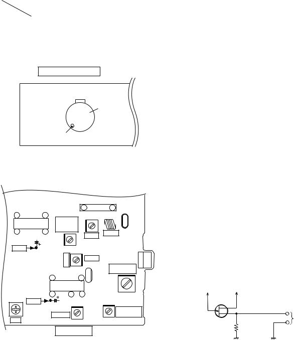
CD MECHANISM SECTION
Perform steps 1, 2, 3, and 8 ~ 12 of the disassembly method to remove the CD mechanism.
How to remove the turntable up/down/loading motor (See Fig. 10-3)
1.Remove the screws (A1) x 2 pcs., to remove the turntable up/down/loading motor.
How to remove the pickup (See Fig. 10-4)
1.Remove the screws (B1) x 2 pcs., to remove the shaft (B2) x 1 pc.
2.Remove the stop washer (B3) x 1 pc., to remove the gear (B4) x 1 pc.
3.Remove the pickup.
Note:
After disconnecting the optical pickup connector wrap the front end of connector in conductive aluminum foil so as to prevent damage to the optical pickup by static electricity.
Turntable Up/Down/
Loading Motor
Motor
PWB 
(A1) x2 ø2.6 x5mm
|
Figure 10-3 |
(B1) x2 |
(B3) x1 |
ø2.6 x6mm |
|
Pickup
(B2) x1 |
CD Mechanism |
|
(B4) x1 |
||
|
||
|
Figure 10-4 |
– 10 –
CD-C606/1900,CP-C606/1900
ADJUSTMENT
MECHANISM SECTION
∙ Driving Force Check
Torque Meter |
Specified Value |
|
|
Play: TW-2412 |
Tape 1: Over 80 g |
|
Tape 2: Over 80 g |
|
|
∙ Torque Check
Torque Meter |
Specified Value |
|
|
|
|
|
Tape 1 |
Tape 2 |
|
|
|
Play: TW-2111 |
30 to 60 g. cm |
30 to 60 g.cm |
|
|
|
Fast forward: TW-2231 |
— |
60 to 120 g.cm |
|
|
|
Rewind: TW-2231 |
— |
60 to 120 g.cm |
|
|
|
∙ Tape Speed
|
Test Tape |
Adjusting |
Specified |
Instrument |
|
|
Point |
Value |
Connection |
|
|
|
|
|
Normal |
MTT-111 |
Volume in |
3,000 ± |
Speaker |
speed |
|
motor |
30 Hz |
terminal |
|
|
(MM1) |
|
(Load |
|
|
|
|
resistance: |
|
|
|
|
8 ohms) |
|
|
|
|
|
TAPE MECHANISM
MM 1
Motor
Volume in motor
Figure 11-1 ADJUSTMENT POINTS
TUNER SECTION
fL: Low-range frequency fH: High-renge frequency
∙ AM IF/RF
Signal generator: 400 Hz, 30%, AM modulated
Test Stage |
Frequency |
Frequency |
Setting/ |
Instrument |
|
|
|
Display |
Adjusting |
Connection |
|
|
|
|
|
Parts |
|
IF |
450 kHz |
1,720 kHz |
T382 |
*1 |
|
|
|
|
|
|
|
Band |
— |
530 kHz |
(fL): T333 |
*2 |
|
Coverage |
|
|
|
1.1 ± 0.1 V |
|
|
|
|
|
|
|
Tracking |
990 kHz |
990 kHz |
(fL): T331 |
*1 |
|
|
|
|
|
|
|
*1. Input: Antenna (CNP301), |
Output: TP301 |
|
|||
*2. Input: Antenna (CNP301), |
Output: TP302 |
|
|||
∙ FM RF
Signal generator: 1 kHz, 22.5 kHz dev., FM modulated
Test Stage |
Frequency |
Frequency |
Serring/ |
Instrument |
|
|
Display |
Adjusting |
Connection |
|
|
|
Point |
|
|
|
|
|
|
Band |
— |
87.50 MHz |
T301(fL): |
*1 |
Coverage |
|
|
3.4 V ± 50 mV |
|
|
|
|
|
|
RF |
98.00 MHz |
98.00 MHz |
L312 |
*2 |
|
(10-30 dB) |
|
|
|
|
|
|
|
|
*1. Input: Antenna (CNP301), Output: TP302
*2. Input: Antenna (CNP301), Output: Speaker terminal
∙ FM Detection
Signal generator: 10.7 MHz, FM sweep generator
Test |
Frequency |
Frequency |
Adjusting |
Instrument |
Stage |
|
Display |
Parts |
Connection |
|
|
|
|
|
Detection |
10.7 MHz |
98.00 MHz |
T381 |
Input: Pin 1 of |
|
|
|
|
IC303 |
|
|
|
|
Output: TP302 |
|
|
|
|
|
IF |
10.7 MHz |
98.00 MHz |
T302(Turn |
Input: Pin 1 of |
|
|
|
the core of |
IC301 |
|
|
|
transformer |
Output: TP302 |
|
|
|
T381 fully |
|
|
|
|
counter- |
|
|
|
|
clookwise.) |
|
|
|
|
|
|
∙ VCO Frequency |
|
|
|
|
|
|
|
|
|
|
IC301 |
|
|
11 |
|
1 |
|
|
9 |
|
1 |
BF301 |
|
FM Band |
|
T302 |
L312 |
|
|||
|
IC302 |
|
|
|
|
|
||
|
|
Coverage |
|
|
|
|
||
12 |
|
22 |
fL |
|
|
|
FM RF |
|
C354 |
|
|
|
FM IF |
||||
|
T301 |
|
|
|
|
|||
|
|
|
|
|
|
|||
|
|
|
|
|
|
|
||
TP301 |
|
CF351 |
T382 |
|
|
|
||
|
|
|
|
|
|
|||
|
|
|
|
|
|
AM IF |
|
|
|
|
|
|
|
|
|
AM Tracking |
|
|
|
|
|
|
|
|
fL |
|
|
|
12 |
|
|
1 |
CF301 |
|
|
|
|
|
|
|
|
|
||
|
|
|
IC303 |
|
|
|
|
|
VR381 |
|
13 |
21 |
24 |
|
|
T331 |
|
TP302 |
C386 |
T381 |
|
T333 |
|
|||
|
|
|
|
AM Band |
||||
|
|
|
|
|
|
|
|
|
|
|
FM DET |
|
|
|
|
Coverage fL |
|
VCO |
|
|
|
|
|
|
|
|
MAIN PWB
Frequency |
Frequency |
Adjusting |
Instrument |
|
Display |
Parts |
Connection |
|
|
|
|
98.00 MHz |
98.00 MHz |
VR381* |
Pin 13, Pin 21 |
(60 dB) |
|
|
and ground |
|
|
|
of IC303 |
|
* Adjust for 76 kHz ± 200 Hz. |
|
Notes: |
|
After preparing the test circuit shown in Fig 11-3, connect the |
CNP301 |
Pin 13 , Pin 21 and ground of the IC303 with test circuit, and |
AM LOOP |
|
ANTENNA |
measure the Value. |
|
At this time, apply a standard unmodulated signal input and |
|
adjust the VCO. |
Pin 13 of IC303 Pin 21 of IC303 |
|
||
G |
D |
FET : 2SK19 or 2SK54 |
|
|
|
||
|
|
|
|
|
S |
|
TO FREQUENCY |
|
|
|
COUNTER |
|
|
10 kΩ |
|
Figure 11-2 ADJUSTMENT POINTS |
Figure 11-3 |
– 11 –
CD-C606/1900,CP-C606/1900
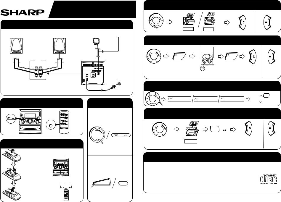
TEST MODE
• Setting the test mode
Any one of test mode can be set by pressing several keys as follows.
<REC. PAUSE> + <DISC. SKIP> + <POWER> |
TEST: CD operation test |
|
|||||||||||
• TEST mode |
|
|
|
|
|
|
|
|
|||||
Function — CD test mode |
|
|
|
|
|
|
|
||||||
Setting of TEST mode |
|
|
|
|
|
|
|
|
|||||
|
|
|
|
|
|
|
|
||||||
|
|
|
|
|
|
|
|
|
|
|
|||
Indication of CD TST mode (Fig. 12-1) |
|
|
|
|
IL is not performed. |
||||||||
|
|
|
OPEN/CLOSE operation is manual operation. |
|
|
|
|||||||
|
|
|
|
|
|
|
|
||||||
|
|
|
) or ( |
) key. |
|
|
|
|
|||||
The pickup can be moved by using the ( |
|
||||||||||||
|
|
|
|
||||||||||
|
|
|
|
<MEMORY> |
<MEMORY> |
|
|
<MEMORY> |
<STOP> |
||||
|
|
|
|
LASER ON |
|
Tracking on the spot. |
|
|
Tracking on the spot. |
|
STOP |
||
|
|
|
|
|
|
|
|
||||||
|
|
|
|
|
|
SERVO OFF PLAY |
|
|
SERVO ON PLAY |
|
|||
|
|
<PLAY> key input |
|
TOC. IL is performed, and the ordinary PLAY is performed. |
|
Press <STOP> key. |
|
Stop |
||||
|
|
|
|
|
||||||||
|
|
|
|
If the following key is pressed during PLAY, it is possible |
|
|
|
|
||||
|
|
|
|
to specify directly any Track No. |
|
|
|
|
|
|
|
|
|
|
|
|
<Disc Number 1> key: Track 4 |
|
|
|
|
|
|
|
|
|
|
|
|
<Disc Number 2> key: Track 9 |
|
|
|
|
|
|
|
|
|
|
|
|
<Disc Number 3> key: Track 15 |
|
|
|
|
|
|
|
|
Note: |
|
|
|
|
|
|
|
|
|
|
||
Only in STOP state it is possible to slide the pickup with the ( |
|
) or ( |
) key. |
|
|
|
|
|||||
VOL. --- Last memory |
|
|
|
|
|
|
|
|
|
|
||
BAL. --- CENTER |
|
|
|
|
|
|
|
|
|
|
||
R.GEQ. --- FLAT |
|
|
1 |
2 |
3 |
|
|
|
|
|
||
X-BAS --- OFF |
|
|
|
|
|
|
||||||
Canceling method - POWER OFF |
|
|
|
|
|
|
|
|
||||
|
|
|
|
|
|
|
|
|
|
|
|
|
Figure 12-1
CD SECTION
Since this CD system incorporates the following automatic adjustment function, when the pickup is replaced, it is not necessary to readjust it.
Since this CD unit does not need adjustment, the combination of PWB and laser pickup unit is not restricted.
• Automatic adjustment item
1.Focus offset (Fig. 12-2)
2.Tracking offset (Fig. 12-3)
3.E/F balance (tracking error balance) (Fig. 12-4)
4.RF level AGC function (HF level: constant)
5.RF level automatic follow-up of the tracking gain
This automatic adjustment is performed each time a disc is changed. Therefore, each disc is played back using the optimal settings.
10ms |
|
Enlarged |
|
View |
|
0.50 V |
|
|
|
|
|
IC1 20 |
FE |
|
10ms |
|
|
0.50 V |
|
|
IC1 7 |
TE |
TRACKING |
|
|
OFF-SET |
|
|
1 ADJUST |
|
|
2 |
Figure 12-3
0.1s |
|
|
0.50 V |
|
|
IC1 20 |
FE |
|
|
|
FOCUS |
|
|
OFF-SET |
|
|
ADJUST |
0.1s |
|
|
0.50 V |
|
|
IC1 7 |
TE |
TRACKING |
|
|
|
|
|
OFF-SET |
|
|
1 ADJUST |
|
|
2 |
|
|
Figure 12-2 |
200 ms |
TRACKING/ |
|
1V/diV |
ERROR |
|
IC 1 |
15 |
BARANCE |
|
TO |
1 ADJUST |
|
|
|
200 ms |
|
|
1V/diV |
|
|
IC 1 |
7 |
2 |
|
TE |
|
|
|
|
|
|
Figure 12-4 |
– 12 –
CD-C606/1900,CP-C606/1900
NOTES ON SCHEMATIC DIAGRAM
∙Resistor:
To differentiate the units of resistors, such symbol as K and M are used: the symbol K means 1000 ohm and the symbol M means 1000 kohm and the resistor without any symbol is ohm-type resistor. Besides, the one with “Fusible” is a fuse type.
∙Capacitor:
To indicate the unit of capacitor, a symbol P is used: this symbol P means micro-micro-farad and the unit of the capacitor without such a symbol is microfarad. As to electrolytic capacitor, the expression “capacitance/withstand voltage” is used.
(CH), (TH), (RH), (UJ): Temperature compensation (ML): Mylar type
(P.P.): Polypropylene type
∙Schematic diagram and Wiring Side of P.W.Board for this model are subject to change for improvement without prior notice.
REF. NO |
DESCRIPTION |
POSITION |
|
|
|
SW1 |
OPEN/CLOSE |
ON—OFF |
|
|
|
SW2 |
MECHA UP |
ON—OFF |
|
|
|
SW3 |
DISC NUMBER |
ON—OFF |
|
|
|
SW4 |
PICKUP IN |
ON—OFF |
|
|
|
SW605 |
TAPE 1 MAIN |
ON—OFF |
|
|
|
SW606 |
TAPE 2 MAIN |
ON—OFF |
|
|
|
SW607 |
TAPE 1 RECORD |
ON—OFF |
|
|
|
SW608 |
TAPE 1 PLAY |
ON—OFF |
|
|
|
SW701 |
POWER |
ON—OFF |
|
|
|
SW702 |
VOLUME UP |
ON—OFF |
|
|
|
SW703 |
VOLUME DOWN |
ON—OFF |
|
|
|
SW704 |
PLAY |
ON—OFF |
|
|
|
∙The indicated voltage in each section is the one measured by Digital Multimeter between such a section and the chassis with no signal given.
1.In the tuner section, ( ) indicates AM
< > indicates FM stereo
2.In the main section, a tape is being played back.
3.In the deck section, a tape is being played back. ( ) indicates the record state.
4.In the power section, a tape is being played back.
5.In the CD section, the CD is stopped.
∙Parts marked with “ ” (
” ( 


 ) are important for maintaining the safety of the set. Be sure to replace these parts with specified ones for maintaining the safety and performance of the set.
REF. NO |
DESCRIPTION |
POSITION |
|
|
|
SW705 |
FAST FORWARD |
ON—OFF |
|
|
|
SW706 |
REWIND |
ON—OFF |
|
|
|
SW707 |
OPEN/CLOSE |
ON—OFF |
|
|
|
SW708 |
STOP |
ON—OFF |
|
|
|
SW709 |
DISC SKIP |
ON—OFF |
|
|
|
SW710 |
X-BASS |
ON—OFF |
|
|
|
SW711 |
FUNCTION |
ON—OFF |
|
|
|
SW712 |
BAND |
ON—OFF |
|
|
|
SW714 |
MEMORY |
ON—OFF |
|
|
|
SW715 |
TUNING UP |
ON—OFF |
|
|
|
SW716 |
TUNING DOWN |
ON—OFF |
|
|
|
FRONT |
FRONT |
|
|
|
|
|
VIEW |
VIEW |
|
|
|
|
|
|
|
|
|
|
FRONT |
|
|
|
|
|
|
VIEW |
|
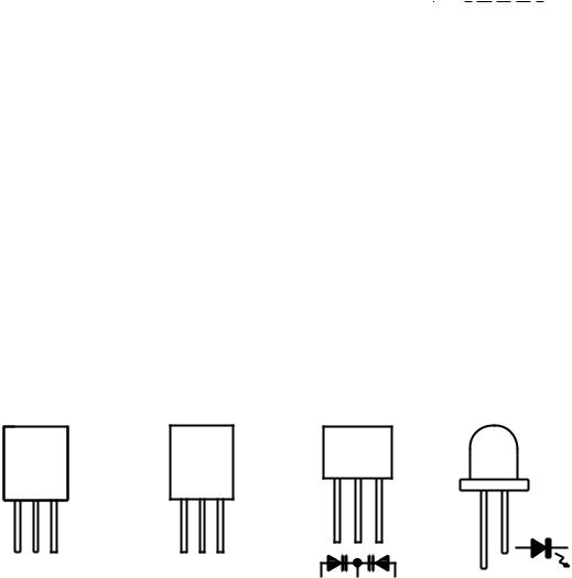
E C B |
B C E |
|
|
|
|
|
(S)(G)(D) |
(D)(G)(S) |
1 |
2 |
3 |
SLI342UCJ1 |
|
(1) (2) (3) |
(3) (2) (1) |
|||||
|
||||||
2SC2389 SE |
2SA1318 |
SVC211C |
|
|||
KRA102 M |
|
SVC348S |
|
|||
KRA109 M
KRC102 M
KRC104 M
KRC107 M
KTA1266 GR
KTA1271 Y
KTA1273 Y
KTC3194 Y
KTC3199 GR
KTC3203 Y
Figure 13 TYPES OF TRANSISTOR AND LED
– 13 –

CD-C606/1900,CP-C606/1900
NOTES ON SCHEMATIC DIAGRAM
∙Resistor:
To differentiate the units of resistors, such symbol as K and M are used: the symbol K means 1000 ohm and the symbol M means 1000 kohm and the resistor without any symbol is ohm-type resistor. Besides, the one with “Fusible” is a fuse type.
∙Capacitor:
To indicate the unit of capacitor, a symbol P is used: this symbol P means micro-micro-farad and the unit of the capacitor without such a symbol is microfarad. As to electrolytic capacitor, the expression “capacitance/withstand voltage” is used.
(CH), (TH), (RH), (UJ): Temperature compensation (ML): Mylar type
(P.P.): Polypropylene type
∙Schematic diagram and Wiring Side of P.W.Board for this model are subject to change for improvement without prior notice.
REF. NO |
DESCRIPTION |
POSITION |
|
|
|
SW1 |
OPEN/CLOSE |
ON—OFF |
|
|
|
SW2 |
MECHA UP |
ON—OFF |
|
|
|
SW3 |
DISC NUMBER |
ON—OFF |
|
|
|
SW4 |
PICKUP IN |
ON—OFF |
|
|
|
SW605 |
TAPE 1 MAIN |
ON—OFF |
|
|
|
SW606 |
TAPE 2 MAIN |
ON—OFF |
|
|
|
SW607 |
TAPE 1 RECORD |
ON—OFF |
|
|
|
SW608 |
TAPE 1 PLAY |
ON—OFF |
|
|
|
SW701 |
POWER |
ON—OFF |
|
|
|
SW702 |
VOLUME UP |
ON—OFF |
|
|
|
SW703 |
VOLUME DOWN |
ON—OFF |
|
|
|
SW704 |
PLAY |
ON—OFF |
|
|
|
∙The indicated voltage in each section is the one measured by Digital Multimeter between such a section and the chassis with no signal given.
1.In the tuner section, ( ) indicates AM
< > indicates FM stereo
2.In the main section, a tape is being played back.
3.In the deck section, a tape is being played back. ( ) indicates the record state.
4.In the power section, a tape is being played back.
5.In the CD section, the CD is stopped.
∙Parts marked with “ ” (
” ( 


 ) are important for maintaining the safety of the set. Be sure to replace these parts with specified ones for maintaining the safety and performance of the set.
REF. NO |
DESCRIPTION |
POSITION |
|
|
|
SW705 |
FAST FORWARD |
ON—OFF |
|
|
|
SW706 |
REWIND |
ON—OFF |
|
|
|
SW707 |
OPEN/CLOSE |
ON—OFF |
|
|
|
SW708 |
STOP |
ON—OFF |
|
|
|
SW709 |
DISC SKIP |
ON—OFF |
|
|
|
SW710 |
X-BASS |
ON—OFF |
|
|
|
SW711 |
FUNCTION |
ON—OFF |
|
|
|
SW712 |
BAND |
ON—OFF |
|
|
|
SW714 |
MEMORY |
ON—OFF |
|
|
|
SW715 |
TUNING UP |
ON—OFF |
|
|
|
SW716 |
TUNING DOWN |
ON—OFF |
|
|
|
FRONT |
FRONT |
|
|
|
|
|
VIEW |
VIEW |
|
|
|
|
|
|
|
|
|
|
FRONT |
|
|
|
|
|
|
VIEW |
|
E C B |
B C E |
|
|
|
|
|
(S)(G)(D) |
(D)(G)(S) |
1 |
2 |
3 |
SLI342UCJ1 |
|
(1) (2) (3) |
(3) (2) (1) |
|||||
|
||||||
2SC2389 SE |
2SA1318 |
SVC211C |
|
|||
KRA102 M |
|
SVC348S |
|
|||
KRA109 M
KRC102 M
KRC104 M
KRC107 M
KTA1266 GR
KTA1271 Y
KTA1273 Y
KTC3194 Y
KTC3199 GR
KTC3203 Y
Figure 13 TYPES OF TRANSISTOR AND LED
– 13 –

CD-C606/1900,CP-C606/1900
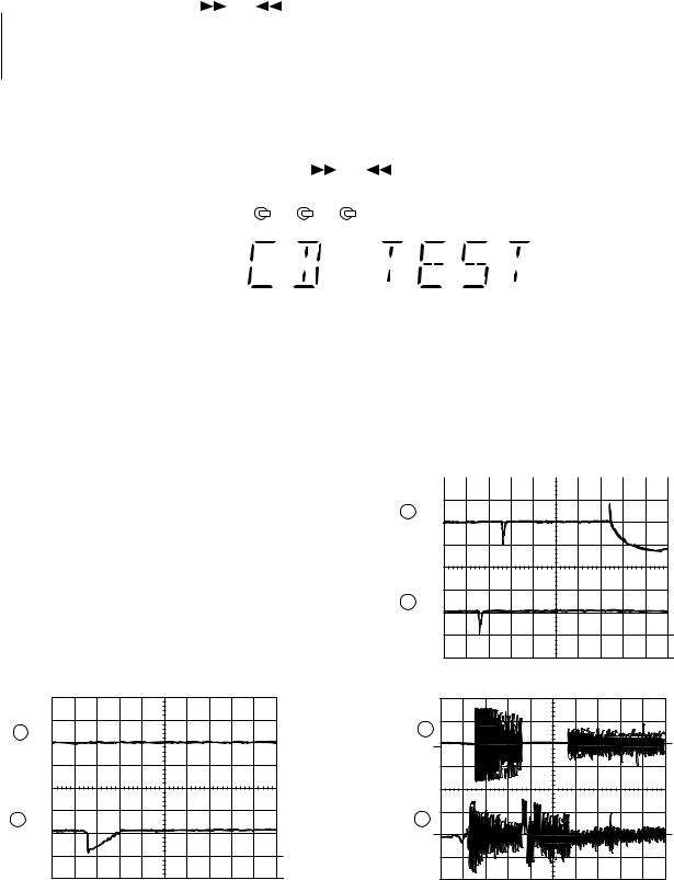
WAVEFORMS OF CD CIRCUIT
STOP  PLAY
PLAY
FOCUS SERCH
1 |
5ms |
|
|
|
0.50 V |
FE |
|
||
|
IC1 20 |
|
||
2 |
5ms |
|
|
|
5.0 V |
|
3 |
||
IC1 54 DRF |
||||
|
||||
|
|
|
1 |
|
|
|
|
CUE |
|
3 |
0.5ms |
|
|
|
1.00 V |
HF |
|
||
|
IC1 41 |
|
||
|
0.5ms |
|
1 |
|
4 |
|
|
||
5.0 V |
|
2 |
||
IC1 4 |
HFL |
|||
|
||||
5 |
0.5ms |
|
|
|
5.0 V |
TES |
3 |
||
|
IC1 36 |
|
||
|
|
|
REVIEW |
|
3 |
0.5ms |
|
|
|
1.00 V |
HF |
|
||
|
IC1 41 |
|
||
4 |
0.5ms |
|
1 |
|
|
|
|||
5.0 V |
HFL |
2 |
||
|
IC1 4 |
|
||
5 |
0.5ms |
|
|
|
5.0 V |
TES |
3 |
||
|
IC1 36 |
|
||
6 |
50ms |
|
CUE |
|
10.0 V |
JP+ |
|||
|
IC1 33 |
|
||
7 |
50ms |
|
|
|
10.0 V |
JP- |
|
||
|
IC1 32 |
|
||
8 |
50ms |
|
|
|
0.50 V |
JP |
|
||
|
IC1 14 |
|
||
9 |
50ms |
|
|
|
1.00 V |
TE |
|
||
|
IC1 7 |
|
||
6 |
0.5ms |
|
|
|
10.0 V |
|
|
||
1 |
IC1 33 |
JP+ |
|
|
7 |
0.5ms |
|
|
|
10.0 V |
|
|
||
1 |
IC1 32 |
JP- |
|
|
8 |
0.5ms |
|
|
|
0.50 V |
|
|
||
1 |
IC1 14 |
JP |
|
|
9 |
0.5ms |
|
|
|
1.00 V |
|
|
||
1 |
IC1 7 |
TE |
|
|
6 |
50ms |
|
REVIEW |
|
10.0 V |
JP+ |
|||
|
IC1 33 |
|
||
7 |
50ms |
|
|
|
10.0 V |
JP- |
|
||
|
IC1 32 |
|
||
8 |
50ms |
|
|
|
0.50 V |
JP |
|
||
|
IC1 14 |
|
||
9 |
50ms |
|
|
|
1.00 V |
TE |
|
||
|
IC1 7 |
|
||
|
|
|
– 14 – |
|
0.5ms 6 10.0 V
IC1 33 JP+
0.5ms 7 10.0 V
IC1 32 JP- 0.5ms
8 0.50 V
IC1 14 JP 0.5ms
9 1.00 V
IC1 7 TE
PLAY NORMAL DISC
TN0=01
10 |
20ms |
|
1.00 V |
SPO |
|
|
IC1 27 |
|
11 |
20ms |
|
2.00 V |
|
|
|
IC2 12 CLV+ |
|
|
|
PLAY TCD-712 (140mm) |
|
50ms |
TN0=01 |
10 |
|
|
1.00 V |
SPO |
|
|
IC1 27 |
|
50ms
11 2.00 V
IC2 12 CLV+
PLAY TCD-712
5s
12 100mV
IC1 29 SLD
1
0.5s
12 100mV
IC1 29 SLD
1
|
|
|
|
|
|
|
|
|
|
|
|
|
CD-C606/1900,CP-C606/1900 |
|||||
|
|
|
TO MAIN SECTION |
|
|
|
|
|
DISC NUMBER SW1 |
OPEN/CLOSE |
M3 TURNTABLE |
UP/DOWN |
|
TO DISPLAY |
||||
|
|
|
|
(TO IC401) |
|
|
|
|
|
|
|
SECTION |
||||||
|
|
|
|
|
|
|
|
|
|
|
|
|
|
|
||||
|
|
|
|
1 2 3 4 5 6 |
CNP11 |
|
|
|
|
|
M |
|
|
|||||
|
|
|
|
|
|
|
|
|
|
|
SW2 |
MECHAUP SW3 |
– |
+ LOADING MOTOR |
SOLM2 SOLENOID |
|
||
|
|
|
|
|
|
|
|
|
|
|
|
|
||||||
|
|
|
|
|
|
|
|
|
|
|
CNS10 10 9 8 7 6 5 4 3 2 1 |
|
|
|||||
|
+B1 |
+7V |
|
|
|
|
|
|
|
GND (D) |
MECHA UP GND (D) |
DISK NO. OPEN/CLOSE GND (D) |
M– M+ SOL– SOL+ |
|
|
|||
|
|
|
|
|
|
|
|
|
|
|
CNP10 10 9 8 7 6 5 4 3 2 1 |
|
|
|||||
|
|
|
|
|
SWITCHING |
|
|
|
|
|
|
|
|
|
|
|
||
|
|
|
|
|
REGULATOR |
|
|
|
|
|
|
|
|
|
|
|
||
|
|
|
|
|
|
Q51 |
|
|
|
|
|
|
|
|
|
|
|
|
|
|
|
|
40 37 36 |
38 39 |
27 |
24 |
25 |
|
|
|
|
|
|
|
|
|
|
|
|
|
43 XVDD |
RCHO LCHO LVDD |
LVSS RVSS |
CONT4 |
CONT1 |
CONT2 |
|
|
|
|
|
|
|
|
|
|
|
|
|
41 RVDD |
|
|
|
|
|
|
|
|
|
|
|||||
|
+5V |
36 LVDD |
|
|
|
|
|
|
|
|
|
|
|
|
|
|
|
|
|
|
|
23 VDD |
|
IC2 |
|
CONT3 26 |
|
|
|
|
|
|
|
|
|
||
|
|
|
5 ISET |
|
|
|
|
|
|
|
|
|
|
|
|
|
|
|
|
|
|
LC78622N |
|
/RES. /CQCK. COIN SQOUT. RWC. WRQ |
|
|
|
|
|
|
|
|
|
|
|||
|
|
|
6 VVDD |
|
58 |
|
|
|
|
|
|
|
|
|
||||
|
|
|
SERVO/SIGNAL |
|
|
|
|
|
|
|
|
|
||||||
|
|
|
|
~ |
|
|
|
|
|
|
|
|
|
|||||
|
|
16.93MHz |
44 XOUT |
CONTROL |
|
53 |
|
|
|
|
|
|
|
|
|
|||
|
XL1 |
45 XIN |
|
EFMO EFMIN |
CLV+ |
JP– |
|
CONTROL/CE |
|
|
|
|
|
|
|
|
||
|
|
|
|
|
|
|
|
|
|
|
|
|||||||
|
|
|
9 10 |
12 ~ |
20 |
|
|
|
|
|
|
|
|
|
||||
|
|
|
|
|
|
|
|
|
|
|
|
|
|
|
||||
|
|
VOLTAGE REGULATOR |
|
|
32 ~ |
40 43 44 |
|
|
CL, DAT, SELIAL |
SL+. SL–. DRF |
|
+B1 |
|
|
|
PU-IN SW |
||
|
|
|
|
JP– |
CV+ SLC |
SL1 |
CE 53 |
|
|
|
|
|||||||
|
Q52 |
|
|
|
|
|
+B5 |
|
||||||||||
|
|
|
DAT 52 |
|
|
|
|
|||||||||||
|
|
|
|
|
|
|
|
|||||||||||
|
|
|
|
CL 51 |
|
|
|
|
||||||||||
|
+4.3V |
|
|
|
|
|
|
|
|
|||||||||
|
|
|
DRF 54 |
42 41 |
20 40 24 18 28 39 38 37 36 |
|||||||||||||
+5V |
|
|
64 VCC1 |
|
IC1 |
|
|
SL+ 31 |
|
|
|
|
|
|
|
|
23 |
|
|
|
LA9241M |
|
SL– 30 |
|
|
|
|
|
IC3 |
|
35 |
||||||
|
|
|
|
|
|
|
|
|
|
|
||||||||
|
|
|
|
SERVO AMP. |
|
|
|
|
|
M63001FP |
|
~ |
||||||
|
|
|
|
|
|
|
|
|
|
29 |
||||||||
LASER DRIVER |
|
|
|
|
|
|
|
SLD 29 |
|
25 |
|
|
FOCUS/ |
|
||||
|
|
|
|
|
|
|
|
|
|
|
22 |
|||||||
|
|
|
|
|
|
|
SP 23 |
|
20 |
|
TRACKING/ |
|
||||||
Q1 |
|
62 LD0 |
|
|
|
|
SPO 27 |
|
17 |
|
SPIN/SLED |
|
21 |
|||||
|
|
|
|
FIN21 |
FIN12 E3 |
|
FD 16 |
|
2 |
|
|
DRIVER |
|
14 |
||||
|
|
|
|
F4 |
TO 15 |
|
1 |
|
|
|
|
|
|
~ |
||||
|
|
|
|
|
|
|
|
|
|
|
8 |
|||||||
|
|
|
|
|
|
|
|
|
6 7 4 5 |
15 16 26 27 |
||||||||
|
|
|
|
|
|
|
|
|
|
|||||||||
|
|
|
|
|
|
|
|
|
|
|
|
M2 |
M |
|
|
|
||
|
|
|
|
|
|
|
|
|
|
|
|
MOTORSLED |
|
|
|
|||
|
|
|
|
|
|
|
|
|
TRACKING COIL |
FOCUS COIL |
|
|
|
|
|
|
|
SW4 |
|
|
|
|
|
|
|
|
|
|
M1 |
|
|
|
|
PICKUP IN |
|||
|
|
|
|
|
|
|
|
|
|
SPINDLE |
M |
|
|
|
||||
|
|
|
|
|
|
|
|
|
|
MOTOR |
|
|
|
|||||
|
|
|
|
PICKUP UNIT |
|
|
|
|
|
|
|
|
|
|||||
|
|
|
|
|
|
|
|
|
|
|
|
|
|
|
|
|
||
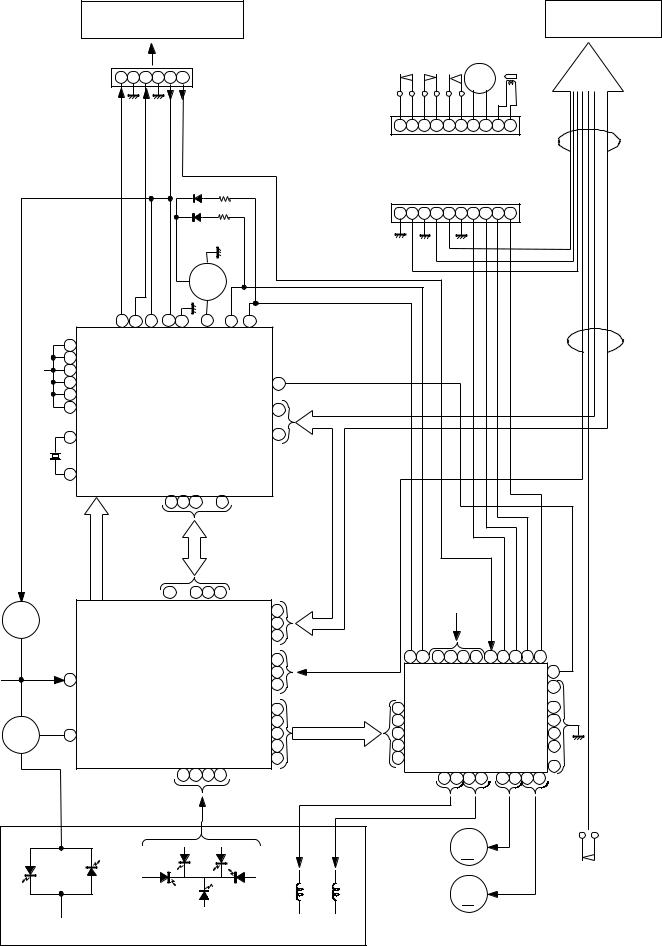
Figure 15 BLOCK DIAGRAM (1/3)
– 15 –
 Loading...