


MINI COMPONENT SYSTEM
MODEL
CD-SW340
OPERATION MANUAL
Thank you for purchasing this SHARP product.
To obtain the best performance from this product, please read this manual carefully. It will guide you in operating your SHARP product.
CD-SW340 Mini Component System consisting of CD-SW340 (main unit), CP-S340 (front speaker) and CP-SW340 (Subwoofer).
Accessories
Please confirm that the following accessories are included.
Remote control 1 |
AM loop antenna 1 |
FM antenna 1 |
(RRMCGA161AWSA) |
(QANTL0010AWZZ) |
(92LFANT1535A) |
|
|
|
Note:
Only the above accessories are included.
CD-SW340
Important Instruction
2
SPECIAL NOTES
CAUTION: TO REDUCE THE RISK OF ELECTRIC SHOCK, DO NOT REMOVE COVER (OR BACK).
NO USER-SERVICEABLE PARTS INSIDE. REFER SERVICING TO QUALIFIED SERVICE PERSONNEL.
Explanation of Graphical Symbols:
The lightning flash with arrowhead symbol, within an equilateral triangle, is intended to alert the user to the presence of uninsulated “dangerous voltage” within the product’s enclosure that may be of sufficient magnitude to constitute a risk of electric shock to persons.
The exclamation point within an equilateral triangle is intended to alert the user to the presence of important operating and maintenance (servicing) instructions in the literature accompanying the appliance.
WARNING: TO REDUCE THE RISK OF FIRE OR ELECTRIC SHOCK, DO NOT EXPOSE THIS APPLIANCE TO RAIN OR MOISTURE.
This product is classified as a CLASS 1 LASER PRODUCT Caution - use of any controls, adjustments or procedures other then those specified herein may result in hazardous radiation exposure.
Note to CATV system installer:
This reminder is provided to call the CATV system installer's attention to Article 820-40 of the National Electrical Code that provides guidelines for proper grounding and, in particular, specifies that the cable ground shall be connected to the grounding system of the building, as close to the point of cable entry as practical.
NOTE
This equipment has been tested and found to comply with the limits for a Class B digital device, pursuant to Part 15 of the FCC Rules. These limits are designed to provide reasonable protection against harmful interference in a residential installation. This equipment generates, uses, and can radiate radio frequency energy and, if not installed and used in accordance with the instructions, may cause harmful interference to radio communications. However, there is no guarantee that interference will not occur in a particular installation. If this equipment does cause harmful interference to radio or television reception, which can be determined by turning the equipment off and on, the user is encouraged to try to correct the interference by one or more of the following measures:
Reorient or relocate the receiving antenna.
Increase the separation between the equipment and receiver.
Connect the equipment into an outlet on a circuit different from that to which the receiver is connected.
Consult the dealer or an experienced radio/TV technician for help.
WARNING
FCC Regulations state that any unauthorized changes or modifications to this equipment not expressly approved by the manufacturer could void the user's authority to operate this equipment.
NOTES
It is the intent of Sharp that this product be used in full compliance with the copyright laws of the United States and that prior permission be obtained from copyright owners whenever necessary.
Licensed under one or more of U.S. Pat. 4,972,484, 5,214,678, 5,323,396, 5,530,655, 5,539,829, 5,544,247, 5,606,618, 5,610,985,
5,740,317, 5,777,992, 5,878,080 or 5,960,037. |
0303 |
|
FOR YOUR RECORDS
For your assistance in reporting this unit in case of loss or theft, please record below the model number and serial number which are located on the rear of the unit.
Please retain this information.
Model number .......................................................
Serial number .......................................................
Date of purchase .......................................................
Place of purchase .......................................................
0202

IMPORTANT SAFETY INSTRUCTIONS
CD-SW340
Electricity is used to perform many useful functions, but it can also cause personal injuries and property damage if improperly handled. This product has been engineered and manufactured with the highest priority on safety. However, improper use can result in electric shock and/or fire. In order to prevent potential danger, please observe the following instructions when installing, operating and cleaning the product. To ensure your safety and prolong the service life of this product, please read the following precautions carefully before use.
1)Read these instructions.
2)Keep these instructions.
3)Heed all warnings.
4)Follow all instructions.
5)Do not use this apparatus near water.
6)Clean only with dry cloth.
7)Do not block any ventilation openings. Install in accordance with the manufacturer’s instructions.
8)Do not install near any heat sources such as radiators, heat registers, stoves, or other apparatus (including amplifiers) that produce heat.
9)Do not defeat the safety purpose of the polarized or grounding-type plug. A polarized plug has two blades with one wider than the other. A grounding type plug has two blades and a third grounding prong. The wide blade or the third prong are provided for your safety. If the provided plug does not fit into your outlet, consult an electrician for replacement of the obsolete outlet.
10)Protect the power cord from being walked on or pinched particularly at plugs, convenience receptacles, and the point where they exit from the apparatus.
11)Only use attachments/accessories specified by the manufacturer.
12)Use only with the cart, stand, tripod, bracket, or table
specified by the manufacturer, or sold with the apparatus. When a cart is used, use caution when moving the cart/ apparatus combination to avoid injury from tip-over.
13)Unplug this apparatus during lightning storms or when unused for long periods of time.
14)Refer all servicing to qualified service personnel. Servicing is required when the apparatus has been damaged in any way, such as powersupply cord or plug is damaged, liquid has been spilled or objects have fallen into the apparatus, the apparatus has been exposed to rain or moisture, does not operate normally, or has been dropped.
Additional Safety Information
15)Power Sources - This product should be operated only from the type of power source indicated on the marking label. If you are not sure of the type of power supply to your home, consult your product dealer or local power company. For product intended to operate from battery power, or other sources, refer to the operating instructions.
16)Overloading - Do not overload wall outlets, extension cords, or integral convenience receptacles as this can result in a risk of fire or electric shock.
17)Object and Liquid Entry - Never push objects of any kind into this product through openings as they may touch dangerous voltage points or short-out parts that could result in a fire or electric shock. Never spill liquid of any kind on the product.
Important Instruction
3
CD-SW340 IMPORTANT SAFETY INSTRUCTIONS (continued)
Important Instruction
18)Damage Requiring Service - Unplug this product from the wall outlet and refer servicing to qualified service personnel under the following conditions :
a)When the AC cord or plug is damaged,
b)If liquid has been spilled, or objects have fallen into the product,
c)If the product has been exposed to rain or water,
d)If the product does not operate normally by following the operating instructions. Adjust only those controls that are covered by the operating instructions as an improper adjustment of other controls may result in damage and will often require extensive work by a qualified technician to restore the product to its normal operation,
e)If the product has been dropped or damaged in any way, and
f)When the product exhibits a distinct change in performance - this indicates a need for service.
19)Replacement Parts - When replacement parts are required, be sure the service technician has used replacement parts
specified by the manufacturer or have the same characteristics as the original part. Unauthorized substitutions may result in fire, electric shock, or other hazards.
20)Safety Check - Upon completion of any service or repairs to this product, ask the service technician to perform safety checks to determine that the product is in proper operating condition.
21)Wall or ceiling mounting - When mounting the product on a wall or ceiling, be sure to install the product according to the method recommended by the manufacturer.
22)Power Lines - An outside antenna system should not be located in the vicinity of overhead power lines or other electric light or power circuits,or where it can fall into such power lines or circuits. When installing an outside antenna system, extreme care should be taken to keep from touching such power lines or circuits as contact with them might be fatal.
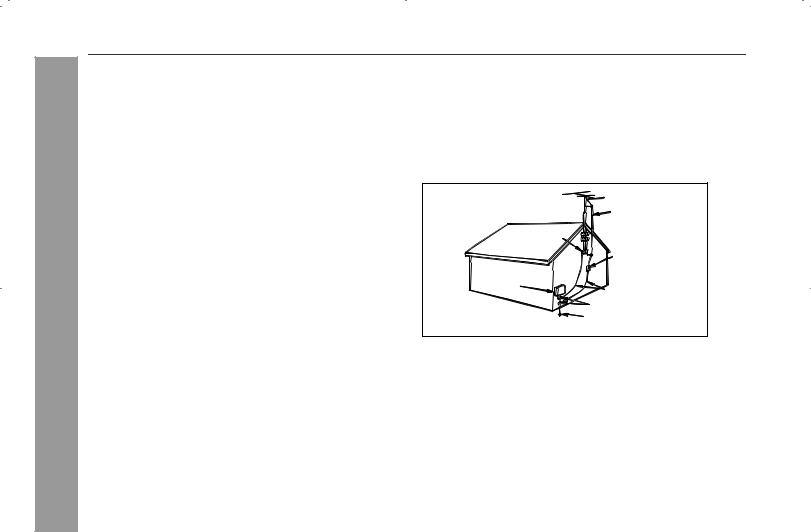
23)Outdoor Antenna Grounding - If an outside antenna or cable system is connected to the product, be sure the antenna or cable system is grounded so as to provide some protection against voltage surges and built-up static charges. Article810 of the National Electrical Code, ANSI/NFPA 70, provides information with regards to proper grounding of the mast and supporting structure, grounding of the lead-in wire to an antenna discharge unit, connection to grounding electrodes, and requirements for the grounding electrode.
Example of antenna grounding as per
National Electrical Code, ANSI/NFPA 70
|
ANTENNA LEAD IN WIRE |
|
GROUND |
|
CLAMP |
|
ANTENNA DISCHARGE UNIT |
|
(NEC SECTION 810-20) |
ELECTRIC |
|
SERVICE |
|
EQUIPMENT |
GROUNDING CONDUCTORS |
|
|
|
(NEC SECTION 810-21) |
|
GROUND CLAMPS |
|
P OWER SERVICE GROUNDING |
NEC - NATIONAL ELECTRICAL CODE |
ELECTRODE SYSTEM |
S2898A |
(NEC ART 250, PART H) |
24)Protective Attachment Plug - The product is equipped with an attachment plug having overload protection. This is a safety feature. See Instruction Manual for replacement or resetting of protective device. If replacement of the plug is required, be sure the service technician has used a replacement plug specified by the manufacturer that has the same overload protection as the original plug.
25)Stand - Do not place the product on an unstable cart, stand, tripod or table. Placing the product on an unstable base can cause the product to fall, resulting in serious personal injuries as well as damage to the product. Use only a cart, stand, tripod, bracket or table recommended by the manufacturer or sold with the product. When mounting the product on a
wall, be sure to follow the manufacturer’s intructions. Use only the mounting hardware recommended by the manufacturer.
4

ENERGY STAR® Program Information
Products that have earned the ENERGY STAR® are designed to protect the environment through superior energy efficiency.
To comply with the ENERGY STAR® standards mentioned above, please cancel the demonstration mode, as described on page 13.
ENERGY STAR® is a U.S. registered mark.
Special Note
Supply of this product does not convey a license nor imply any right to distribute content created with this product in revenue-generating broadcast systems (terrestrial, satellite, cable and/or other distribution channels), revenue-generating streaming applications (via Internet, intranets and/or other networks), other revenuegenerating content distribution systems (pay-audio or audio-on- demand applications and the like) or on revenue-generating physical media (compact discs, digital versatile discs, semiconductor chips, hard drives, memory cards and the like). An independent license for such use is required. For details, please visit http://mp3licensing.com MPEG Layer-3 audio coding technology licensed from Fraunhofer IIS and Thomson.
Contents
Page
General Information
Precautions . . . . . . . . . . . . . . . . . . . . . . . . . . . . . . . . . . . . . . . . . 6 Controls and indicators . . . . . . . . . . . . . . . . . . . . . . . . . . . .7 - 10
Preparation for Use
System connections . . . . . . . . . . . . . . . . . . . . . . . . . . . . . .11 - 13 Remote control . . . . . . . . . . . . . . . . . . . . . . . . . . . . . . . . . . . . . 14
Basic Operation
General control . . . . . . . . . . . . . . . . . . . . . . . . . . . . . . . . . . . . . 15 Setting the clock (Remote control only). . . . . . . . . . . . . . . . . . 16
CD or MP3/WMA disc Playback
Listening to a CD or MP3/WMA disc . . . . . . . . . . . . . . . . .17 - 19 Advanced CD or MP3/WMA disc playback . . . . . . . . . . . .19 - 21 MP3/WMA Navigation (only for MP3/WMA files) . . . . . . . .22 - 25
Radio
Listening to the AM/FM stations . . . . . . . . . . . . . . . . . . . .26 - 27
Tape Playback
Listening to a cassette tape (TAPE 1 or TAPE 2) . . . . . . .28 - 29
Tape Recording
Recording on a cassette tape . . . . . . . . . . . . . . . . . . . . . . .29 - 31
Advanced Features
Timer and sleep operation (Remote control only). . . . . . .31 - 34 Enhancing your system . . . . . . . . . . . . . . . . . . . . . . . . . . . . . . 35
References
Troubleshooting chart . . . . . . . . . . . . . . . . . . . . . . . . . . . . .36 - 37 Maintenance . . . . . . . . . . . . . . . . . . . . . . . . . . . . . . . . . . . . . . . . 38 Specifications . . . . . . . . . . . . . . . . . . . . . . . . . . . . . . . . . . .38 - 39
CONSUMER LIMITED WARRANTY . . . . . . . . . . . . . .Back cover
CD-SW340
General Information
5
CD-SW340 Precautions
General Information
General
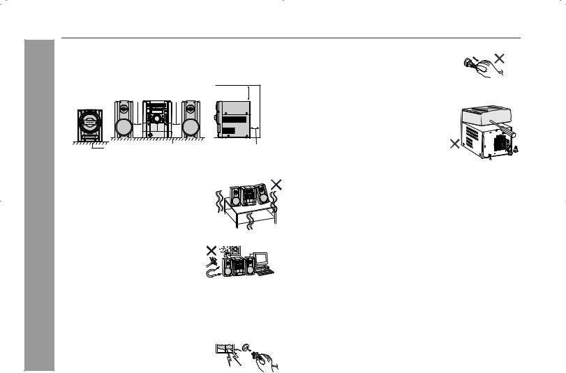
Please ensure that the equipment is positioned in a well ventilated area and ensure that there is at least 4" (10 cm) of free space along the sides, top and back of the equipment.
4" (10 cm) |
4" (10 cm) |
Floor |
Table |
4" (10 cm) |
4" (10 cm) |
Do not place subwoofer system on the same surface as main unit to prevent sound interruption during playback.
Use the unit on a firm, level surface free from vibration.
Keep the unit away from direct sunlight,
strong magnetic fields, excessive dust, humidity and electronic/electrical equipment (home computers,
facsimiles, etc.) which generate electrical noise.
Do not place anything on top of the unit.
Do not expose the unit to moisture, to temperatures higher than 140˚F (60˚C) or to extremely low temperatures.
If your system does not work properly, disconnect the AC power cord from the AC outlet. Plug the AC power cord back in, and then turn on your system.
In case of an electrical storm, unplug the unit for safety.
Hold the AC power plug by the head when removing it from the AC outlet, as pulling the cord can damage internal wires.
The AC power plug is used as a disconnect device and shall always remain readily operable.
Do not remove the outer cover, as this may result in electric shock. Refer internal service to your local SHARP service facility.
This unit should only be used within the range of 41˚F - 95˚F (5˚C - 35˚C).
Warning:
The voltage used must be the same as that specified on this unit. Using this product with a higher voltage other than that which is specified is dangerous and may result in a fire or other type of accident causing damage. SHARP will not be held responsible for any damage resulting from use of this unit with a voltage other than that which is specified.
Volume control
The sound level at a given volume setting depends on speaker efficiency, location, and various other factors. It is advisable to avoid exposure to high volume levels, which occurs while turning the unit on with the volume control setting up high, or while continually listening at high volumes. Excessive sound pressure from earphones and headphones can cause hearing loss.
6
Controls and indicators
CD-SW340
TIMER
CD
5
4
 3
3
2
1
PLAYBACK (PLAY & STOP) |
RECORD/PLAYBACK |
AUDIO
PHONES IN
Front panel |
|
|
Reference page |
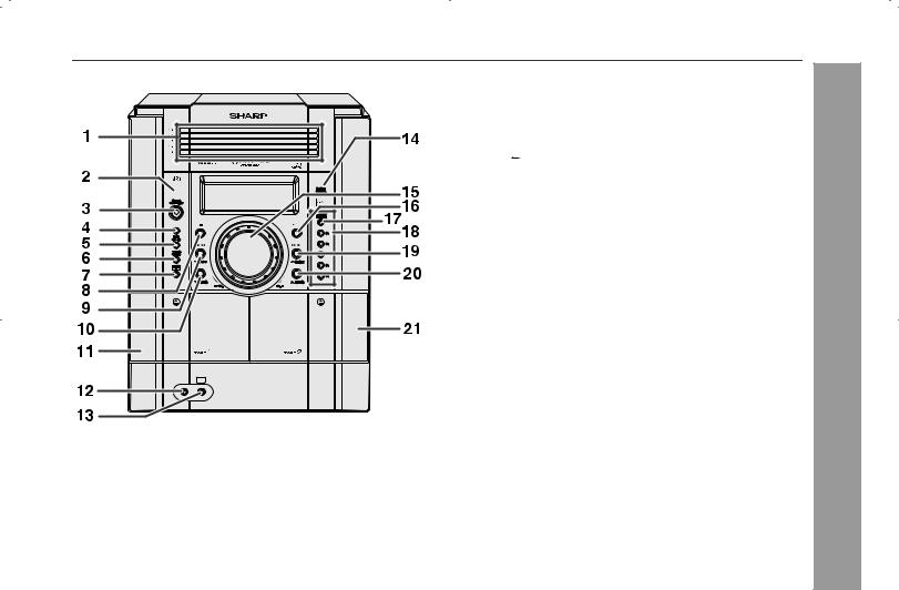
1. Disc Trays . . . . . . . . . . . . . . . . . . . . . . . . |
. . . . . . . . . . . . . . . 18 |
2. Timer Indicator . . . . . . . . . . . . . . . . . . . . . |
. . . . . . . . . . . . . . 33 |
3. Power On/Stand-by Button . . . . . . . . . . . |
. . . . . . . . . . . . . . 15 |
4. CD Button . . . . . . . . . . . . . . . . . . . . . . . . . |
. . . . . . . . . . . . . . 17 |
5. Tape (1 2) Button . . . . . . . . . . . . . . . . . |
. . . . . . . . . . . . . . 28 |
6. Tuner (Band) Button . . . . . . . . . . . . . . . . |
. . . . . . . . . . . . . . 26 |
7. Audio In Button . . . . . . . . . . . . . . . . . . . . |
. . . . . . . . . . . . . . 35 |
8. CD or Tape Stop Button . . . . . . . . . . . . . |
. . . . . . . . . . . 19, 29 |
9. CD Track Down or Fast Reverse, Tape 2 Rewind, |
|
Tuner Preset Down, Time Down Button |
16, 19, 26, 27, 29, 32 |
10. Tuning Down, Cursor Down Button . . . . |
. . . . . . . . . . . 22, 26 |
11. Tape 1 Cassette Compartment . . . . . . . . |
. . . . . . . . . . . . . . 28 |
12. Headphone Jack . . . . . . . . . . . . . . . . . . . |
. . . . . . . . . . . . . . 35 |
13. Audio In Jack . . . . . . . . . . . . . . . . . . . . . . |
. . . . . . . . . . . . . . 35 |
14. Remote Sensor . . . . . . . . . . . . . . . . . . . . . |
. . . . . . . . . . . . . . 14 |
15. Volume Control . . . . . . . . . . . . . . . . . . . . |
. . . . . . . . . . . . . . 15 |
16. CD Play or Repeat, Tape Play Button . . . |
. . . . . . . . 17, 20, 28 |
17. Disc Tray Open/Close Button . . . . . . . . . |
. . . . . . . . . . . . . . 17 |
18. Disc Number Select Buttons . . . . . . . . . . |
. . . . . . . . . . . . . . 17 |
19. CD Track Up or Fast Forward, Tape 2 Fast Forward, |
|
Tuner Preset Up, Time Up Button . . . . 16, 19, 26, 27, 29, 32 |
|
20. Tuning Up, Cursor Up Button . . . . . . . . . |
. . . . . . . . . . . 22, 26 |
21. Tape 2 Cassette Compartment . . . . . . . . |
. . . . . . . . . . . . . . 28 |
General Information
7
CD-SW340
General Information
8
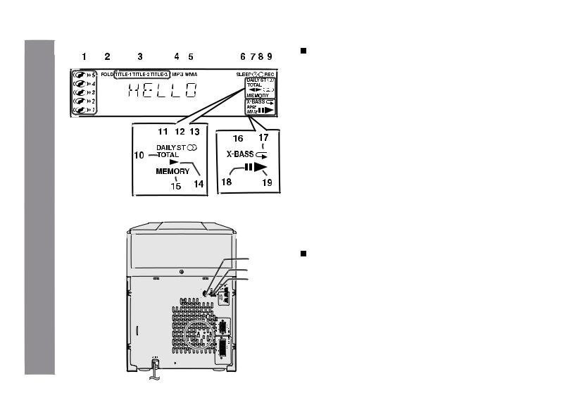
Controls and indicators (continued)
Display |
Reference page |
|
1. Disc Number Indicators |
||
. . . . . . . . . . . 18 |
||
2. MP3/WMA Folder Indicator . . . . . . . . . . . . . . |
. . . . . . . . . . . 22 |
|
3. MP3/WMA Title Indicators . . . . . . . . . . . . . . . |
. . . . . . . . . . . 22 |
|
4. MP3 Indicator . . . . . . . . . . . . . . . . . . . . . . . . . |
. . . . . . . . . . . 18 |
|
5. WMA Indicator . . . . . . . . . . . . . . . . . . . . . . . . |
. . . . . . . . . . . 18 |
|
6. Sleep Indicator . . . . . . . . . . . . . . . . . . . . . . . . |
. . . . . . . . . . . 34 |
|
7. Timer Play Indicator . . . . . . . . . . . . . . . . . . . . |
. . . . . . . . . . . 32 |
|
8. Timer Recording Indicator . . . . . . . . . . . . . . . |
. . . . . . . . . . . 32 |
|
9. Tape 2 Record Indicator . . . . . . . . . . . . . . . . |
. . . . . . . . . . . 30 |
|
10. Total Indicator . . . . . . . . . . . . . . . . . . . . . . . . . |
. . . . . . . . . . . 23 |
|
11. Daily Timer Indicator . . . . . . . . . . . . . . . . . . . |
. . . . . . . . . . . 32 |
|
12. FM Stereo Mode Indicator . . . . . . . . . . . . . . . |
. . . . . . . . . . . 26 |
|
13. FM Stereo Receiving Indicator . . . . . . . . . . . |
. . . . . . . . . . . 26 |
|
14. Tape Play Indicator . . . . . . . . . . . . . . . . . . . . |
. . . . . . . . . . . 30 |
|
15. Memory Indicator . . . . . . . . . . . . . . . . . . . . . . |
. . . . . . . . . . . 21 |
|
16. Extra Bass Indicator . . . . . . . . . . . . . . . . . . . . |
. . . . . . . . . . . 15 |
|
17. Disc Repeat Play Indicator . . . . . . . . . . . . . . |
. . . . . . . . . . . 20 |
|
18. Disc Pause Indicator . . . . . . . . . . . . . . . . . . . |
. . . . . . . . . . . 19 |
|
19. Disc Play Indicator . . . . . . . . . . . . . . . . . . . . . |
. . . . . . . . . . . 18 |
|
3 |
Rear panel |
Reference page |
|
|
|
|||
|
4 |
|
||
|
1. Cooling Fan . . . . . . . . . . . . . . . . . . . . . . . . . . . |
. . . . . . . . . . . 13 |
||
|
5 |
2. AC Power Cord . . . . . . . . . . . . . . . . . . . . . . . . |
. . . . . . . . . . . 13 |
|
|
6 |
3. FM 75 Ohms Antenna Jack . . . . . . . . . . . . . . |
. . . . . . . . . . . 12 |
|
|
7 |
4. AM Antenna Ground Terminal . . . . . . . . . . . |
. . . . . . . . . . . 12 |
|
|
|
5. AM Loop Antenna Terminal . . . . . . . . . . . . . . |
. . . . . . . . . . . 12 |
|
|
|
6. Subwoofer Light-up Jack . . . . . . . . . . . . . . . |
. . . . . . . . . . . 12 |
|
|
8 |
7. Speaker Light-up Jacks . . . . . . . . . . . . . . . . . |
. . . . . . . . . . . 12 |
|
1 |
8. Subwoofer Terminals |
12 |
||
|
||||
|
9. Front Speaker Terminals |
12 |
||
|
9 |
|||
|
|
|
||
2 |
|
|
|
|
|
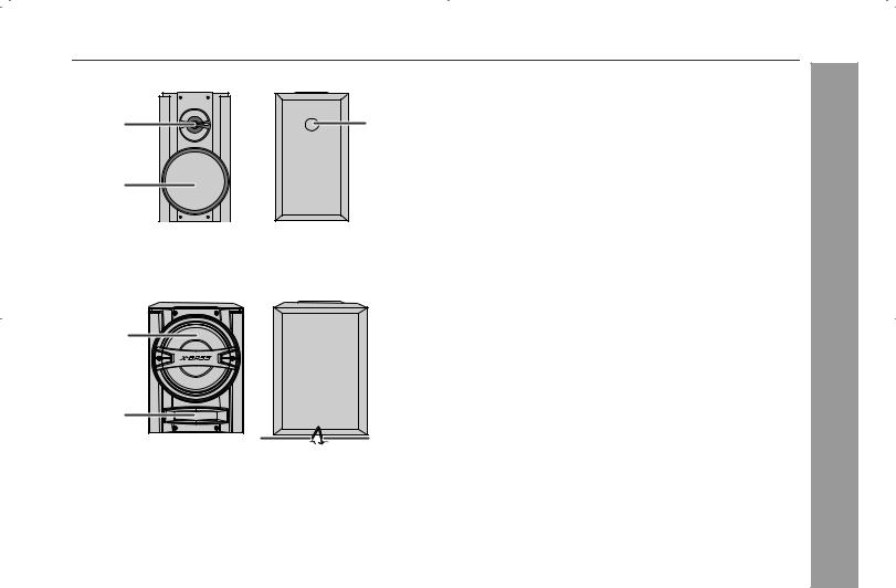
Front Speaker |
|
|
1. Tweeter |
1 |
3 |
2. Woofer |
3. Bass Reflex Duct |
||
|
|
4. Speaker Wire |
|
|
5. Speaker Light-Up Wire |
2
4 


 5
5
1 |
|
2 |
|
3 |
4 |
Subwoofer
1.Subwoofer
2.Bass Reflex Duct
3.Subwoofer Light-Up Wire
4.Speaker Wire
CD-SW340
General Information
9
CD-SW340 Controls and indicators (continued)
General Information
1 |
|
|
|
8 |
13 |
17 |
|
14 |
18 |
||
9 |
|||
15 |
19 |
||
10 |
|||
2 |
|
20 |
|
|
|
||
11 |
16 |
21 |
|
12 |
|||
|
|
||
|
22 |
23 |
3
4 |
|
24 |
25 |
|
5 |
26 |
27 |
28 |
29 |
6 |
|
|
|
|
7 |
|
|
|
|
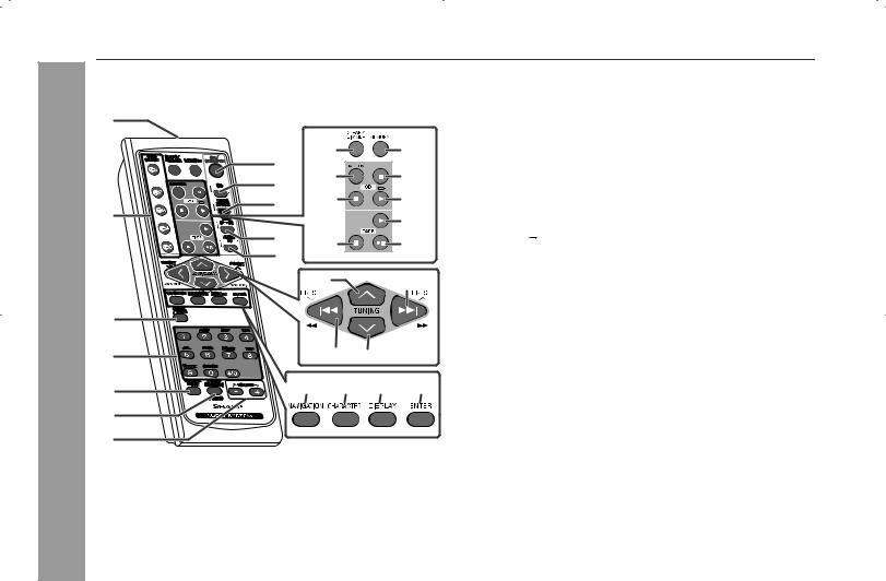
Remote control |
|
|
Reference page |
1. Remote Control Transmitter . . . . . . . . . . . . . |
. . . . . . . . . . . 14 |
2. Disc Number Select Buttons . . . . . . . . . . . . . |
. . . . . . . . . . . 17 |
3. Clock/Timer Button . . . . . . . . . . . . . . . . . . . . |
. . . . . . . . 16, 32 |
4. Character Input/Disc Direct Search Buttons |
. . . . . . . . 20, 24 |
5. Equalizer Mode Select Button . . . . . . . . . . . . |
. . . . . . . . . . . 15 |
6. Extra Bass (Surround)/Demo Button . . . . . . |
. . . . . . . . 13, 15 |
7. Volume Up and Down Buttons . . . . . . . . . . . |
. . . . . . . . . . . 15 |
8. Power On/Stand-by Button . . . . . . . . . . . . . . |
. . . . . . . . . . . 15 |
9. CD Button . . . . . . . . . . . . . . . . . . . . . . . . . . . . |
. . . . . . . . . . . 17 |
10. Tuner (Band) Button . . . . . . . . . . . . . . . . . . . |
. . . . . . . . . . . 26 |
11. Tape (1 2) Button . . . . . . . . . . . . . . . . . . . . |
. . . . . . . . . . . 28 |
12. Audio In Button . . . . . . . . . . . . . . . . . . . . . . . |
. . . . . . . . . . . 35 |
13. Clear/Dimmer Button . . . . . . . . . . . . . . . . . . . |
. . . . . . . . 15, 21 |
14. Disc Random Button . . . . . . . . . . . . . . . . . . . |
. . . . . . . . . . . 20 |
15. Disc Stop Button . . . . . . . . . . . . . . . . . . . . . . |
. . . . . . . . . . . 19 |
16. Tape Stop Button . . . . . . . . . . . . . . . . . . . . . . |
. . . . . . . . . . . 29 |
17. Memory Button . . . . . . . . . . . . . . . . . . . . . . . . |
. . 16, 21, 27, 32 |
18. Disc Pause Button . . . . . . . . . . . . . . . . . . . . . |
. . . . . . . . . . . 19 |
19. Disc Play or Repeat Button . . . . . . . . . . . . . . |
. . . . . . . . 17, 20 |
20. Tape Play Button . . . . . . . . . . . . . . . . . . . . . . |
. . . . . . . . . . . 28 |
21. Tape 2 Record Pause Button . . . . . . . . . . . . |
. . . . . . . . . . . 29 |
22. Tuning Up, Cursor Up Button . . . . . . . . . . . . |
. . . . . . . . 22, 26 |
23. Disc Track Up or Fast Forward, Tape Fast Forward, |
|
Tuner Preset Up, Time Up, Cursor Right Button . . . . . . . . . . |
|
. . . . . . . . . . . . . . . . . . . . . . . . . . . . . . . . . 16, 19, 26, 27, 29, 32 |
|
24. Disc Track Down or Fast Reverse, Tape Fast Rewind, |
|
Tuner Preset Down, Time Down, Cursor Left Button . . . . . . |
|
. . . . . . . . . . . . . . . . . . . . . . . . . . . . . . . . . 16, 19, 26, 27, 29, 32 |
|
25. Tuning Down, Cursor Down Button . . . . . . . |
. . . . . . . . 22, 26 |
26. MP3/WMA Navigation Mode Select Button . |
. . . . . . . . . . . 22 |
27. Character Button . . . . . . . . . . . . . . . . . . . . . . |
. . . . . . . . . . . 22 |
28. MP3/WMA Display Button . . . . . . . . . . . . . . . |
. . . . . . . . . . . 22 |
29. Enter Button . . . . . . . . . . . . . . . . . . . . . . . . . . |
. . . . . . . . . . . 22 |
10
System connections
CD-SW340
Make sure to unplug the AC power cord before making any connections.
 Antenna connection (see page 12)
FM antenna |
AM loop antenna |
|
Right speaker |
Left speaker |
Subwoofer |
|
Speaker light-up wire |
Subwoofer |
|
|
|
Speaker light-up wire |
|
Light-up wire |
Speaker connection |
AC Outlet |
(see page 12) |
(AC 120 V ~ 60 Hz) |
|
AC power connection (see page 13) |
Preparation for Use
11
CD-SW340
Preparation for Use
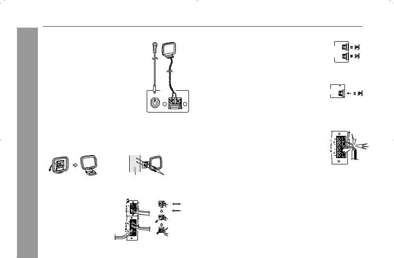
System connections (continued)
Antenna connection
Supplied FM antenna:
Connect the FM antenna wire to the
FM 75 OHMS jack and position the FM antenna wire in the direction where the strongest signal can be received.
Supplied AM loop antenna:
Connect the AM loop antenna to the AM and GND terminals. Position the AM loop antenna for optimum reception. Place the AM loop antenna on a shelf, etc., or attach it to a stand or a wall with screws (not supplied).
Note:
FM |
AM loop |
antenna |
antenna |
|
ANTENNA |
FM |
GND AM |
75 OHMS |
|
Placing the antenna on the unit or near the AC power cord may cause noise pickup. Place the antenna away from the unit for better reception.
Installing the AM loop antenna: |
|
< Assembling > |
< Attaching to the wall > |
Speaker connection
FRONT SPEAKERS:
Connect the black wire to the FRONT SPEAKERS minus
(–) terminal, and the red wire to the FRONT SPEAKERS plus (+) terminal.
SUBWOOFER:
Connect the black wire to the SUBWOOFER minus (–) terminal, and the red wire with purple insulation tube to the SUBWOOFER plus (+) terminal.
Wall Screws (not supplied)
Purple |
Red |
|
|
|
Black |
Speaker Light-Up connection
1 Connect the speaker light-up wires to the |
|
|
|
|
|
|
|
|
|
SPEAKERS LIGHT-UP jacks for speaker |
SPEAKERS UP-LIGHT |
LEFTRIGHT |
|
|
illumination. To turn off the speaker light-up feature, |
|
|
|
|
press the CLEAR/DIMMER button on the remote |
|
|
|
|
|
|
|
|
|
control for 2 seconds or more. |
|
|
|
|
Note:
Placing the right speaker light-up wire to the RIGHT jack and the left speaker light-up wire to the LEFT jack.
2 Connect the subwoofer light-up wire to the
SUBWOOFER LIGHT-UP jack. |
SUB WOOFER LIGHT-UP |
|
|
|
|
Caution:
Never mistake the FRONT SPEAKERS and the SUBWOOFER terminals. The unit or the speakers may be damaged.
If you use other speakers with an impedance lower than that specified, the unit may be damaged. Front speakers: 6 ohms, Subwoofer: 12 ohms. Do not mistake the right and the left channels. The
right speaker is the one on the right side when you face the unit.
Do not let the bare speaker wires touch each other.
Do not stand or sit on the speakers. You may be injured.
Do not allow any objects to fall into or to be placed in the bass reflex duct.
Incorrect
12
 Loading...