


SERVICE MANUAL
CODE: 00ZAR5731/S1E
DIGITAL
MULTIFUNCTIONAL
SYSTEM
MODEL AR-5726/5731
CONTENTS
NOTE FOR SERVICING
[1] PRODUCT OUTLINE . . . . . . . . . . . . . . . . . . . . . . . . . . . . . . . . . . . 1-1 [2] SPECIFICATIONS . . . . . . . . . . . . . . . . . . . . . . . . . . . . . . . . . . . . . . 2-1 [3] CONSUMABLE PARTS . . . . . . . . . . . . . . . . . . . . . . . . . . . . . . . . . . 3-1 [4] EXTERNAL VIEW AND INTERNAL STRUCTURE . . . . . . . . . . . . . 4-1 [5] ADJUSTMENTS . . . . . . . . . . . . . . . . . . . . . . . . . . . . . . . . . . . . . . . 5-1 [6] SIMULATION . . . . . . . . . . . . . . . . . . . . . . . . . . . . . . . . . . . . . . . . . . 6-1 [7] SELF DIAG AND TROUBLE CODE . . . . . . . . . . . . . . . . . . . . . . . . 7-1 [8] MAINTENANCE. . . . . . . . . . . . . . . . . . . . . . . . . . . . . . . . . . . . . . . . 8-1 [9] FIRMWARE UPDATE . . . . . . . . . . . . . . . . . . . . . . . . . . . . . . . . . . . 9-1
[10] ELECTRICAL SECTION . . . . . . . . . . . . . . . . . . . . . . . . . . . . . . . . 10-1
Parts marked with “ ” are important for maintaining the safety of the set. Be sure to replace these parts with specified ones for maintaining the safety and performance of the set.
This document has been published to be used for after sales service only.
The contents are subject to change without notice.
CONTENTS
NOTE FOR SERVICING
1. Warning for servicing . . . . . . . . . . . . . . . . . . . . . . . . . . . . . . . . i 2. Precautions for servicing . . . . . . . . . . . . . . . . . . . . . . . . . . . . . i 3. Note for repairing/replacing the LSU . . . . . . . . . . . . . . . . . . . . i
[1] PRODUCT OUTLINE
1. Line of machines and options . . . . . . . . . . . . . . . . . . . . . . 1 - 1
[2] SPECIFICATIONS
1. Basic function . . . . . . . . . . . . . . . . . . . . . . . . . . . . . . . . . . 2 - 1
[3] CONSUMABLE PARTS
1. Supply system table. . . . . . . . . . . . . . . . . . . . . . . . . . . . . . 3 - 1 2. Maintenance parts list . . . . . . . . . . . . . . . . . . . . . . . . . . . . 3 - 2 3. Developer/Drum life end definition. . . . . . . . . . . . . . . . . . . 3 - 3 4. Production number identification . . . . . . . . . . . . . . . . . . . . 3 - 3 5. Environment conditions . . . . . . . . . . . . . . . . . . . . . . . . . . . 3 - 3
[4] EXTERNAL VIEW AND INTERNAL STRUCTURE
1. External view . . . . . . . . . . . . . . . . . . . . . . . . . . . . . . . . . . . 4 - 1 2. Internal structure . . . . . . . . . . . . . . . . . . . . . . . . . . . . . . . . 4 - 2 3. Operation panel . . . . . . . . . . . . . . . . . . . . . . . . . . . . . . . . . 4 - 3 4. RSPF . . . . . . . . . . . . . . . . . . . . . . . . . . . . . . . . . . . . . . . . . 4 - 4 5. Sensor . . . . . . . . . . . . . . . . . . . . . . . . . . . . . . . . . . . . . . . . 4 - 5 6. Switch . . . . . . . . . . . . . . . . . . . . . . . . . . . . . . . . . . . . . . . . 4 - 5 7. Solenoid/Clutch . . . . . . . . . . . . . . . . . . . . . . . . . . . . . . . . . 4 - 6 8. Drive motor. . . . . . . . . . . . . . . . . . . . . . . . . . . . . . . . . . . . . 4 - 6 9. Lamp . . . . . . . . . . . . . . . . . . . . . . . . . . . . . . . . . . . . . . . . . 4 - 7 10. Fan/Filter . . . . . . . . . . . . . . . . . . . . . . . . . . . . . . . . . . . . . 4 - 7 11. PWB . . . . . . . . . . . . . . . . . . . . . . . . . . . . . . . . . . . . . . . . . 4 - 8 12. Roller . . . . . . . . . . . . . . . . . . . . . . . . . . . . . . . . . . . . . . . . 4 - 8
[5] ADJUSTMENTS
1. Adjustment item list . . . . . . . . . . . . . . . . . . . . . . . . . . . . . . 5 - 1 2. Details of adjustment. . . . . . . . . . . . . . . . . . . . . . . . . . . . . 5 - 1
[6] SIMULATION
1. General . . . . . . . . . . . . . . . . . . . . . . . . . . . . . . . . . . . . . . . 6 - 1 2. Simulation code list . . . . . . . . . . . . . . . . . . . . . . . . . . . . . . 6 - 3 3. Details of simulation . . . . . . . . . . . . . . . . . . . . . . . . . . . . . 6 - 6
[7] SELF DIAG AND TROUBLE CODE
1. Trouble code list . . . . . . . . . . . . . . . . . . . . . . . . . . . . . . . . 7 - 1 2. Details of trouble code . . . . . . . . . . . . . . . . . . . . . . . . . . . 7 - 2
[8] MAINTENANCE
1. Maintenance list . . . . . . . . . . . . . . . . . . . . . . . . . . . . . . . . 8 - 1 2. Details of Maintenance . . . . . . . . . . . . . . . . . . . . . . . . . . . 8 - 3 3. Other related items . . . . . . . . . . . . . . . . . . . . . . . . . . . . . 8 - 31
[9] FIRMWARE UPDATE
1. Firmware update procedure . . . . . . . . . . . . . . . . . . . . . . . 9 - 1
[10] ELECTRICAL SECTION
1. Block diagram . . . . . . . . . . . . . . . . . . . . . . . . . . . . . . . . . 10 - 1 2. Actual wiring chart. . . . . . . . . . . . . . . . . . . . . . . . . . . . . . 10 - 2 3. Signal list. . . . . . . . . . . . . . . . . . . . . . . . . . . . . . . . . . . . . 10 - 9
NOTE FOR SERVICING
This Service Manual uses some photographs to assure safe operation. Please understand the meanings of photographs before servicing.
 WARNING: If this WARNING should be ignored, a serious danger to life or a serious injury may result.
 CAUTION: If this CAUTION should be ignored, injury or damage to property could result.
1. Warning for servicing
1)Be sure to connect the power cord only to a power outlet that meets the specified voltage and current requirements.
Avoid complex wiring, which may lead to a fire or an electric shock.
2)If there is any abnormality such as smoke or an abnormal smell, interrupt the job and disconnect the power plug.
It may cause a fire or an electric shock.
3)Be sure the machine is properly grounded. Failure to ground the machine properly may result in an electric shock or fire.
To protect the machine and the power unit from lightening, grounding must be made.
4)When connecting the ground wire, never connect it to the following points as it may cause an explosion, fire, or an electric shock:
•Gas tube
•Lightning conductor
•A water pipe or a water faucet, which is not recognized as a grounding object by the authorities.
•Grounding wire for telephone line
5)Do not damage, break, or stress the power cord. Do not put heavy objects on the power cord. Do not bend or pull the cord forcefully. It may cause a fire or electric shock.
6)Keep the power cable away from a heat source.
Do not insert the power plug with dust on it into a power outlet. It may cause a fire or an electric shock.
7)Do not put a receptacle with water in it or a metal piece which may drop inside the machine.
It may cause a fire or an electric shock.
8)Do not touch the power plug, insert a telephone jack, perform service or operate the machine with wet or oil hands. It may cause an electric shock.
2. Precautions for servicing
1)When servicing, disconnect the power plug, the printer cable, the network cable, and the telephone line from the machine, except when performing the communication test, etc.
It may cause an injury or an electric shock.
2)There is a high temperature area inside the machine. Use extreme care when servicing.
3)There is a high voltage section inside the machine which may cause an electric shock . Be careful when servicing.
4)Do not disassemble the laser unit. Do not insert a reflective material such as a screwdriver in the laser beam path.
It may damage eyes by reflection of laser beams.
5)When servicing the machine while operating, be careful not to make contact with chains, belts, gear, and any other moving parts.
6)Do not leave the machine with the cabinet disassembled.
Do not allow any person other than a serviceman to touch inside the machine. It may cause an electric shock, a burn, or an injury.
7)When servicing, do not breathe toner, developer, and ink excessively. Do not get them in the eyes.
If toner, developer, or ink enters you eyes, wash it away with water immediately, and consult a doctor if necessary.
8)The machine has got sharp edges inside. Be careful not to damage fingers when servicing.
9)Do not throw toner or a toner cartridge in a fire. Otherwise, toner may pop and burn you.
10)When replacing the lithium battery on the PWB, use only the specified battery. If a battery of different specification is used, it may not be compatible and cause breakdown or malfunction of the machine.
11)When carrying an electric unit or a PWB, use an anti-static (electricity) bag. Failure to do so may cause component failure or machine malfunction.
3. Note for repairing/replacing the LSU
When repairing or replacing, be sure to observe the following items.
1)When repairing or replacing the LSU, be sure to disconnect the power plug from the power outlet.
2)When repairing or replacing the LSU, follow the procedures described in this Service Manual.
3)When checking the operations after repairing the LSU, keep all the parts including the cover installed and perform the operation check.
4)Do not modify the LSU.
5)When visually checking the inside of the machine for the operation check, be careful not to allow laser beams to enter the eyes.
If the above precaution is neglected or an undesignated work is performed, safety may not be assured.
AR-5726/5731 NOTE FOR SERVICING - i
[1] PRODUCT OUTLINE
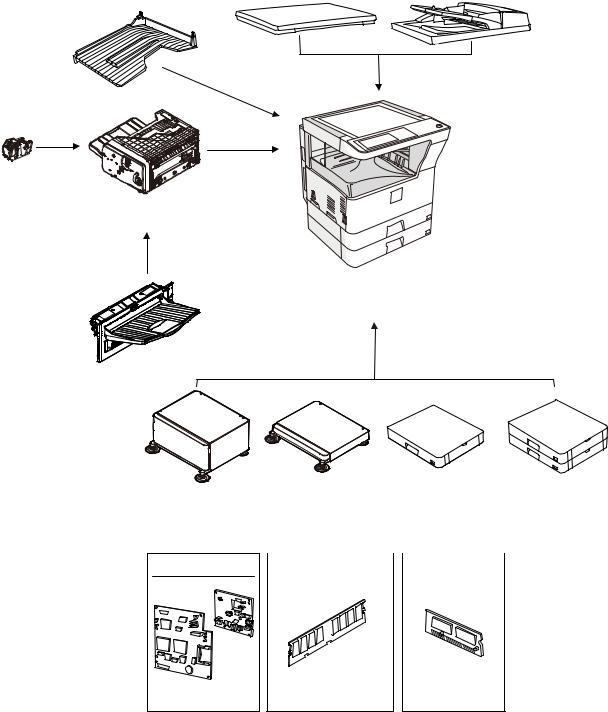
1. Line of machines and options
Document cover |
Reversing single pass feeder |
[MX-VR10] |
[MX-RP10] |
Job separator tray [MX-TR11]
Staple cartridge [MX-SCX1]
Finisher
[MX-FN13]
Installation of the
MX-FN13 is required.
Copier/Printer (SPLC) model [AR-5726/5731]
Exit tray unit
[MX-TE10]
Machine stand |
(Large) |
[MX-DS11] |
FAX expantion kit |
[AR-FX7] |
|
Machine stand |
Paper feed unit |
Paper feed unit |
||||
|
(Small) |
(500 Sheets) |
(500x2 Sheets) |
||||
|
[MX-DS12] |
|
[MX-DE10] |
[MX-DE11] |
|||
|
|
|
|
|
|
|
|
Expantion memory board |
|
FAX memory (8MB) |
|
||||
|
|
|
|
|
|
|
|
[AR-SM5](256MB) [AR-SM6](512MB) [AR-MM9]
AR-5726/5731 PRODUCT OUTLINE 1 - 1
[2] SPECIFICATIONS
1. Basic function
A. Base engine
(1) Type
Type |
Desktop |
|
|
(2) Engine composition
Photoconductor kind |
OPC drum (Drum dia. 30mm) |
|
|
Copying method |
Electronic photo (Laser) |
|
|
Developing system |
Dry, 2-component magnetic brush |
|
development |
|
|
Charging system |
Sawtooth charging |
|
|
Transfer system |
Transfer roller system |
|
|
Cleaning system |
Contact blade system |
|
|
Fusing system |
Heat roller |
|
|
Toner supply method |
Toner supply by front cover open |
|
|
Waste toner disposal |
Toner cartridge collection |
|
|
(3) Dimensions / Weight
External dimensions |
OC model: 623 x 628 x 668mm |
(W x D x H) |
RSPF model: 623 x 628 x 788mm |
|
|
Occupied |
898 x 628mm |
dimensions (W x D) |
|
(when the manual |
|
paper feed tray is |
|
extended) |
|
|
|
Weight |
About 46kg |
|
|
(4) Warmup
Warm-up time |
23 sec or less (26-sheet model) |
|
25 sec or less (31-sheet model) |
|
|
Pre-heat |
Yes |
|
|
Jam recovery time |
About 10sec, excluding fusing warmup, toner |
|
control, etc. |
|
|
Conditions: Leaving for 60 sec after door open, standard conditions, polygon stop.
(5) First copy time
|
26-sheet model |
31-sheet model |
|
|
|
Platen |
4.8 sec |
4.5 sec |
|
|
|
RSPF |
9.3 sec or less |
|
|
|
|
Measuring conditions: When paper of A4 or 8.5” x 11” is fed from the machine tray, with the polygon rotating.
(6) Engine resolution
Writing resolution |
600 x 600dpi |
|
|
Smoothing (Print) |
1200dpi (equivalent) x 600dpi |
|
|
Gradation |
Writing: Binary |
|
|
(7) Printable range
Max. print size |
AB series: 416 x 293mm |
|
(600dpi: 9826dot x 6920dot) |
|
Inch series: 428 x 275mm |
|
(600dpi: 10110dot x 6496dot) |
|
|
Void area image loss |
Front/Rear: Less than 4mm |
|
Right/Left total: Less than 6mm at actual |
|
(100%) size |
|
|
(8) Engine speed (ppm)
Tray |
Paper size |
26-sheet |
31-sheet |
|
model |
model |
|||
|
|
|||
|
|
|
|
|
Tray 1-4 |
A3 |
15 |
17 |
|
|
|
|
|
|
|
B4/8.5 x 13 |
17 |
20 |
|
|
|
|
|
|
|
A4/B5/A5/8.5 x 11/ |
26 |
31 |
|
|
5.5 x 8.5/16K |
|
|
|
|
|
|
|
|
|
A4R/8.5 x 11R/16KR |
18 |
24 |
|
|
|
|
|
|
|
B5R |
21 |
|
|
|
|
|
|
|
|
11 x 17 |
14 |
17 |
|
|
|
|
|
|
|
8.5 x 14 |
16 |
20 |
|
|
|
|
|
|
|
8K |
|
19 |
|
|
|
|
|
|
Manual paper |
A3 |
14 |
17 |
|
feed |
|
|
|
|
8.5 x 13 |
17 |
20 |
||
|
||||
|
|
|
|
|
|
B4 |
16 |
19 |
|
|
|
|
|
|
|
A4/B5/A5/8.5 x 11/ |
23 |
27 |
|
|
5.5 x 8.5/16K |
|
|
|
|
|
|
|
|
|
A4R/8.5 x 11R |
19 |
22 |
|
|
|
|
|
|
|
16KR |
|
23 |
|
|
|
|
|
|
|
B5R |
21 |
24 |
|
|
|
|
|
|
|
11 x 17 |
14 |
16 |
|
|
|
|
|
|
|
8.5 x 14 |
16 |
19 |
|
|
|
|
|
(9) Power source
Voltage/Current |
220 - 240V 8A |
|
|
Frequency |
50/60Hz |
|
|
Power source code |
Inlet type |
|
|
Power switch |
1 power source |
|
|
(10) Power consumption
Maximum rated |
1.45kw |
power consumption |
|
|
|
Shift time to sleep |
Default (1 minute) |
mode |
|
|
|
(11) Memory
Local Memory |
Standard |
32MB |
|
|
|
|
Expansion |
512MB x 2 |
|
|
|
|
Max. |
1056MB |
|
|
|
B. Controller board
(1) Controller board
|
|
SPLC board |
|
|
|
Interface |
Ethernet |
No |
|
|
|
|
USB 2.0 Device |
Full Speed 1slot |
|
|
|
|
Memory |
No |
|
|
|
|
Memory expansion slot |
--- |
|
|
|
C. Operation panel
Type |
Dot matrix LCD, touch panel |
|
|
Size |
Monochrome H-VGA 8.1” |
|
|
Display dot number |
640 x 240 (H-VGA) |
|
|
LCD drive display area |
192 x 72mm |
|
|
LCD backlight |
Fluorescent lamp backlight system |
|
|
LCD contrast adjustment |
Yes |
|
|
AR-5726/5731 SPECIFICATIONS 2 - 1
D. Scanner section
(1) Resolution/Gradation
Reading |
|
Copy mode |
|
|
||
resolution |
|
|
|
|
|
|
Platen |
400 x 600dpi |
|
|
|||
(dpi) |
|
|
||||
|
|
|
|
|
||
RSPF |
400 x 600dpi |
|
|
|||
|
|
|
||||
|
|
|
|
|
|
|
Transmission |
FAX transmission mode |
|
||||
resolusion |
|
|
|
|
|
|
Select mode |
Normal |
Fine |
Super |
Ultra |
||
(dpi) |
||||||
|
text |
text |
fine |
fine |
||
|
|
|||||
|
|
|
|
text |
text |
|
|
|
|
|
|
|
|
|
Input resolution: |
203.2 |
203.2 |
203.2 |
406.4 |
|
|
OC |
x |
x |
x |
x |
|
|
|
293.4 |
293.4 |
391.2 |
586.7 |
|
|
|
|
|
|
|
|
|
Input resolution: |
203.2 |
203.2 |
203.2 |
406.4 |
|
|
RSPF |
x |
x |
x |
x |
|
|
|
293.4 |
293.4 |
391.2 |
586.7 |
|
|
|
|
|
|
|
|
|
Transmission |
203.2 |
203.2 |
203.2 |
406.4 |
|
|
resolution |
x |
x |
x |
x |
|
|
|
97.8 |
195.6 |
391 |
391 |
|
|
|
|
|
|
|
|
|
Half tone |
No |
Yes |
Yes |
Yes |
|
|
|
|
|
|
|
|
Reading |
256 gradations |
|
|
|
|
|
gradation |
|
|
|
|
|
|
|
|
|
|
|
||
Exposure |
Electrodeless xenon lamp |
|
|
|
||
lamp |
|
|
|
|
|
|
|
|
|
|
|
|
|
Output |
Binary |
|
|
|
|
|
gradation |
|
|
|
|
|
|
|
|
|
|
|
|
|
(2) Document table
Type |
Document table fixed type (Flat bed) |
||
|
|
|
|
Scanning area |
297 x 431.8mm |
||
|
|
|
|
Original standard |
Left bottom reference |
||
position |
|
|
|
|
|
|
|
Detection |
Yes |
|
|
|
|
|
|
Detection size |
Inch |
Automatic setting |
|
|
|
series |
11 x 17, 8.5 x 14, 8.5 x 11, |
|
|
|
8.5 x 11R, 5.5 x 8.5 |
|
|
|
Manual setting |
|
|
|
11 x 17, 8.5 x 14, 8.5 x 13 (216 x |
|
|
|
330), 8.5 x 11, 8.5 x 11R, |
|
|
|
5.5 x 8.5, A3, A4, A4R |
|
|
|
|
|
|
AB |
Automatic setting |
|
|
series |
A3, B4, A4, A4R, A5 |
|
|
|
Manual setting |
|
|
|
11 x 17, 8.5 x 14, 8.5 x 13 (216 x |
|
|
|
330), 8.5 x 11, 8.5 x 11R, A3, B4, |
|
|
|
A4, A4R, A5 |
|
|
|
|
(3) Automatic document feeder
Type |
RSPF |
|
|
|
|
|
|
(Automatic duplex document feeder unit) |
|||
|
|
|
|
||
Scan speed |
When in single copy |
|
When in duplex copy |
||
|
|
|
|
|
|
Copy |
31-sheet model: |
|
31-sheet model: |
||
|
|
27 sheets/min |
|
13.6 side/min |
|
|
|
(400 x 600dpi) |
|
(400 x 600dpi) |
|
|
|
26-sheet model: |
|
26-sheet model: |
|
|
|
26 sheets/min |
|
13.6 side/min |
|
|
|
(400 x 600dpi) |
|
(400 x 600dpi) |
|
|
|
|
|
|
|
Fax |
40 sheets/min |
|
17 sheets/min |
||
|
|
(Normal text, A4R) |
|
(Normal text, A4R) |
|
|
|
|
|
|
|
Document set |
Face-up reference |
|
|||
direction |
|
|
|
|
|
|
|
|
|
||
Document standard |
Center reference |
|
|||
position |
|
|
|
|
|
|
|
|
|
||
Document transport |
Sheet through system |
|
|||
system |
|
|
|
|
|
|
|
|
|
||
Document size |
AB series: A3 - A5 |
|
|||
|
|
Inch series: 11 x 17 - 5.5 x 8.5 |
|||
|
|
|
|||
Document weight |
Single face: 35 - 128g/m2, 9 - 34 lbs, |
||||
|
|
Duplex: 52 - 105g/m2, 13.9 - 28 lbs |
|||
Max. loading |
100 sheets (90g/m2) |
|
|||
capacity of |
Paper thickness of 13mm or less can be set. |
||||
documents |
|
|
|
|
|
|
|
|
|||
Transport disable |
OHP, perforated documents, photo, |
||||
document |
catalogue, second original sheet, tracing |
||||
|
|
paper, carbon paper, heat-sensitive paper, |
|||
|
|
wrinkled paper, folded or broken paper, |
|||
|
|
pasted or cut-away paper, documents of |
|||
|
|
many perforated holes (2-hole, 3-hole |
|||
|
|
documents can be used), document printed |
|||
|
|
by an ink ribbon |
|
||
|
|
|
|
|
|
Detection |
Yes |
|
|
|
|
|
|
|
|
|
|
Detection size |
Inch |
Automatic setting |
|||
|
|
series |
11 x 17, 8.5 x 14, 8.5 x 11, |
||
|
|
|
8.5 x 11R, 5.5 x 8.5, A3, A4 |
||
|
|
|
Manual setting |
||
|
|
|
11 x 17, 8.5 x 14, 8.5 x 13 (216 x |
||
|
|
|
330), 8.5 x 11, 8.5 x 11R, |
||
|
|
|
5.5 x 8.5, A3, A4, A4R |
||
|
|
|
|
||
|
|
AB |
Automatic setting |
||
|
|
series |
11 x 17, 8.5 x 11, A3, B4, A4, |
||
|
|
|
A4R, B5, B5R, A5 |
||
|
|
|
Manual setting |
||
|
|
|
11 x 17, 8.5 x 14, 8.5 x 13 (216 x |
||
|
|
|
330), 8.5 x 11, 8.5 x 11R, A3, B4, |
||
|
|
|
A4, A4R, A5 |
|
|
|
|
|
|
|
|
Multi copy |
S-S, S-D, D-D, D-S |
|
|||
|
|
||||
Mixed paper feed |
Enable (Same width only) |
||||
|
|
|
|
|
|
AR-5726/5731 SPECIFICATIONS 2 - 2
E. Paper feed section
Type |
|
Paper feed tray + Multi manual paper feed (Expanded up to 4 trays by installing options.) |
|||||
|
|
|
|
|
|
||
Paper feed method |
|
Paper is fed from the above by the front loading system. |
|
|
|||
|
|
|
|
|
|
|
|
Details of paper feed section |
Tray1 |
|
Tray2 |
|
Manual paper feed tray |
||
|
|
|
|
|
|
|
|
Paper capacity |
Standard paper |
500 sheets |
|
100 sheets |
|||
|
|
(80g/m2) |
|
|
|
|
|
Paper size |
|
A3, B4, A4, A4R, B5, B5R, |
|
A3, B4, A4, A4R, B5R, |
A3, B4, A4, A4R, B5, B5R, A5R, A5, |
||
|
|
|
A5, 11 x 17, 8.5 x 14, |
|
11 x 17, 8.5 x 14 (216 x 356), |
B6R, 11 x 17, 8.5 x 14 (216 x 356), |
|
|
|
|
8.5 x 13, 8.5 x 11, 8.5x11R, |
|
8.5 x 13 (216 x 330), |
8.5 x 13 (216 x 330), 8.5 x 11, |
|
|
|
|
5.5 x 8.5, 8K, 16K, 16KR |
|
8.5 x 11, 8.5 x 11R, 8K, 16KR |
8.5 x 11R, 7.25 x 10.5R, 5.5 x 8.5, |
|
|
|
|
|
|
|
8K, 16K, 16KR, A6R, Envelope*1 |
|
Paper size detection |
|
|
No |
|
Yes |
||
|
|
|
|
||||
Allowable paper type and weight for paper |
56 - 105g/m2/15 - 28lbs Bond |
Multi paper feed: |
|||||
feed |
|
|
|
|
Standard paper (56 - 128g/m2) |
||
|
|
|
|
|
|
Special paper, heavy paper (max. |
|
|
|
|
|
|
|
200g/m2) |
|
|
|
|
|
|
|
Single paper feed: |
|
|
|
|
|
|
|
Standard paper, special paper, |
|
|
|
|
|
|
|
second original, heavy paper (max. |
|
|
|
|
|
|
|
200g/m2), 56200g/m2 (14 - 54lbs) |
|
Paper type |
|
Standard paper (56 - 80g/m2) |
• Standard paper: 100 sheets |
||||
|
|
|
Normal paper (60 - 105g/m2) |
|
|
|
(56 - 80g/m2) |
|
|
|
Letterhead |
|
|
• |
Recycled paper/coarse paper: |
|
|
|
Color paper |
|
|
|
100 sheets |
|
|
|
|
|
|
• Heavy paper (max. 200g/m2): |
|
|
|
|
|
|
|
|
30 sheets |
|
|
|
|
|
|
• |
OHP/Label sheet/gift wrapping |
|
|
|
|
|
|
|
paper: 40 sheets |
|
|
|
|
|
|
• |
Label sheet: 40 sheets |
|
|
|
|
|
|
• |
Envelope (AB series: 10 sheets, |
|
|
|
|
|
|
|
Inch series: 5 sheets) |
|
|
|
|
|
|
|
|
Paper size setting when |
Inch series |
8.5 x 11 |
|
--- |
|||
shipping |
|
|
|
|
|
|
|
|
AB series |
|
A4 |
|
--- |
||
|
|
|
|
||||
|
|
|
|
|
|
|
|
Paper remaining detection |
|
No (paper presence only) |
|
|
|
|
|
|
|
|
|
|
|
|
|
1: Supported envelope kinds: Commercial10 (4 - 1/8” x 9 - 1/2”), International DL (110mm x 220mm), International C5 (162mm x 229mm)
AR-5726/5731 SPECIFICATIONS 2 - 3
F. |
Paper exit section |
|||||
(1) |
Center tray of main unit |
|||||
|
|
|
|
|
||
Paper exit position/ |
|
Main unit top surface face-down paper |
||||
system |
|
|
|
exit |
||
|
|
|
|
|
||
Paper exit capacity |
|
500 sheets (A4, 8.5 x 11, 80g/m2 paper) |
||||
Paper exit paper size/ |
|
All kinds of paper which can be fed |
||||
kind |
|
|
|
|
||
|
|
|
|
|
|
|
Shifter function |
|
|
|
Yes |
||
|
|
|
|
|
||
Paper remaining |
|
Yes |
||||
detection for paper exit |
|
|
||||
|
|
|
|
|
||
G. Copy functions |
|
|
||||
(1) |
Copy magnification ratio |
|||||
|
|
|
|
|
|
|
Copy |
|
AB |
|
25%, 50%, 70%, 81%, 86%, 100%, |
||
magnification |
|
series |
|
115%, 122%, 141%, 200%, 400% |
||
ratio |
|
|
|
|
|
|
|
Inch |
|
25%, 50%, 64%, 77%, 100%, 121%, |
|||
|
|
|
|
|||
|
|
|
series |
|
129%, 200%, 400% |
|
|
|
|
|
|
||
Zoom |
|
25 - 400% |
||||
|
|
|
(Restriction by the document feeder unit: 50 - 200%) |
|||
|
|
|
|
|||
(2) Density/copy image quality process |
||||||
|
|
|
|
|||
Exposure mode |
|
|
Binary: Automatic, Text, Text/Photo, Photo |
|||
|
|
|
||||
Number of manual |
|
5 steps |
||||
steps |
|
|
|
|
||
|
|
|
|
|
|
|
(3) |
Duplex |
|
|
|
|
|
|
|
|
|
|||
System |
|
|
Switchback system |
|||
|
|
|
|
|||
Paper size |
|
|
A3, B4, A4, A4R, B5, B5R, A5, 11 x 17, |
|||
|
|
|
|
|
8.5 x 14, 8.5 x 13, 8.5 x 11, 8.5 x 11R |
|
|
|
|
||||
Type and weight of |
|
56 - 105g/m2/15 - 21.3 lbs Bond |
||||
paper which can be |
|
Duplex print from manual paper feed can be |
||||
passed |
|
|
made. (Except for heavy paper, OHP sheet, |
|||
|
|
|
|
|
and other special paper) |
|
|
|
|
|
|
|
|
When duplex printing is continued in a certain level of temperature, the printing speed may be reduced in order to prevent an abnormal temperature rise in the machine.
(4) Copy functions
Automatic paper selection
Automatic magnification ratio selection
Vertical/horizontal independent magnification ratio
Paper type selection
Auto tray switching
Rotation copy
Electronic sort
Job reservation (only during warm-up)
Program call-out/registration (10 items)
Preheat function
Auto power shut off function
User management (100 items)
Mixed documents feed (MIX only)
Binding margin (Left/Right/Upper)
Edge erase/Center erase (Center/Edge/Center + Edge)
1 set 2 copy
Cover paper/Insert paper (Cover/Back cover only)
Multi shot (2 in 1/4 in 1) (Centering available)
Card shot (Centering available)
Pamphlet mode (Centering available)
Duplex copy direction switching
Large volume document mode
Black/white reverse (except for UK)
Stream feeding mode (ON/OFF switch by the system setting)
H. Printer function
(1) Platform
•IBM PC/AT
•Macintosh
(2) Support OS
|
OS |
SPLC |
|
|
|
Windows |
2000 |
|
|
|
|
|
XP |
Yes |
|
|
|
|
XP x64 |
|
|
|
|
|
Server 2003 |
No |
|
|
|
|
Server 2003 x64 |
|
|
|
|
|
|
|
|
Vista |
Yes |
|
|
|
|
Vista x64 |
|
|
|
|
|
|
|
|
Server 2008 |
|
|
|
|
|
Server 2008 x64 |
|
|
|
|
Mac |
9.0 - 9.2.2 |
|
|
|
No |
|
X 10.2.8 |
|
|
|
|
|
X 10.3.9 |
|
|
|
|
|
X 10.4.11 |
|
|
|
|
|
X 10.5 - 10.5.6 |
|
|
|
|
I. Environmental conditions
(Humidity)
85%
60%
20%
|
10 C |
30 C |
35 C |
|
||
|
|
|
(Temperature) |
|||
|
|
|
|
|
|
|
Standard environmental |
|
Temperature |
|
20 |
- 25°C |
|
conditions |
|
Humidity |
|
|
65 |
± 5%RH |
Usage environmental |
|
Temperature |
|
10 |
- 35°C |
|
conditions |
|
Humidity |
|
|
20 |
- 85%RH |
|
|
Atmospheric |
|
590 - 1013 hPa |
||
|
|
pressure |
|
|
(height: 0 - 2000m) |
|
AR-5726/5731 SPECIFICATIONS 2 - 4
[3] CONSUMABLE PARTS
1. Supply system table
A. East Europe/Russia
No. |
Item |
Content |
|
Life |
|
Model name |
Remarks |
|
|
|
|
|
|
|
|
1 |
Toner cartridge |
Toner cartridge (With IC chip) |
×1 |
33K |
|
MX-312GT |
Life setting by A4 (8.5"×11") 6% document |
|
(black) |
(Toner; Net 700g) |
|
|
|
|
Default: Toner save mode |
|
|
|
|
|
|
|
|
2 |
Developer (black) |
Developer |
×1 |
26cpm: |
75K |
MX-312GV |
|
|
|
(Developer; Net 300g) |
|
31cpm: 100K |
|
|
|
|
|
|
|
|
|
|
|
3 |
Drum |
Drum |
×1 |
26cpm: |
75K |
MX-312GR |
|
|
|
|
|
31cpm: 100K |
|
|
|
|
|
|
|
|
|
|
|
B. Asia Subsidiaries
No. |
Item |
Content |
|
Life |
|
Model name |
Remarks |
|
|
|
|
|
|
|
|
1 |
Toner cartridge |
Toner cartridge (With IC chip) |
×1 |
33K |
|
MX-312AT |
Life setting by A4 (8.5"×11") 6% document |
|
(black) |
(Toner; Net 700g) |
|
|
|
|
Default: Toner save mode |
|
|
|
|
|
|
|
|
2 |
Developer (black) |
Developer |
×1 |
26cpm: |
75K |
MX-312AV |
|
|
|
(Developer; Net 300g) |
|
31cpm: 100K |
|
|
|
|
|
|
|
|
|
|
|
3 |
Drum |
Drum |
×1 |
26cpm: |
75K |
MX-312AR |
|
|
|
|
|
31cpm: 100K |
|
|
|
|
|
|
|
|
|
|
|
C. SMEF/Agent
No. |
Item |
Content |
|
Life |
|
Model name |
Remarks |
|
|
|
|
|
|
|
|
1 |
Toner cartridge |
Toner cartridge (With IC chip) |
×1 |
33K |
|
MX-312FT |
Life setting by A4 (8.5"×11") 6% document |
|
(black) |
(Toner; Net 700g) |
|
|
|
|
Default: Toner save mode |
|
|
|
|
|
|
|
|
2 |
Developer (black) |
Developer |
×1 |
26cpm: |
75K |
MX-312FV |
|
|
|
(Developer; Net 300g) |
|
31cpm: 100K |
|
|
|
|
|
|
|
|
|
|
|
3 |
Drum |
Drum |
×1 |
26cpm: |
75K |
MX-312FR |
|
|
|
|
|
31cpm: 100K |
|
|
|
|
|
|
|
|
|
|
|
AR-5726/5731 CONSUMABLE PARTS 3 - 1
2. Maintenance parts list
A. East Europe/Russia/SMEF
No. |
Item |
Content |
|
Life |
Model |
Remarks |
|
name |
|||||
|
|
|
|
|
|
|
|
|
|
|
|
|
|
1 |
Upper heat roller kit |
Upper heat roller |
×1 |
150K |
AR-310UH |
|
|
|
Fuser gear |
×1 |
|
|
|
|
|
Upper heat roller bearing |
×2 |
|
|
|
|
|
Upper cleaning pad |
×1 |
|
|
|
|
|
Fusing separation pawl (upper) |
×4 |
|
|
|
|
|
Thermistor cleaning pad |
×2 |
|
|
|
|
|
|
|
|
|
|
2 |
Lower heat roller kit |
Lower heat roller |
×1 |
300K |
MX-311LH |
|
|
|
Fusing separation pawl (lower) |
×4 |
|
|
|
|
|
Fuser bearing (lower) |
×2 |
|
|
|
|
|
|
|
|
|
|
3 |
150K PM kit |
Drum separation pawl unit |
×2 |
150K |
MX-311KA |
|
|
|
Transfer roller unit |
×1 |
|
|
|
|
|
DV blade |
×1 |
|
|
|
|
|
DV side sheet F |
×1 |
|
|
|
|
|
DV side sheet R |
×1 |
|
|
|
|
|
Toner filter unit |
×1 |
|
|
|
|
|
|
|
|
|
|
4 |
MC unit |
MC unit |
×10 |
26cpm: 75K (×10) |
MX-311MC |
|
|
|
|
|
31cpm: 100K (×10) |
|
|
|
|
|
|
|
|
|
5 |
Cleaner blade |
Cleaner blade |
×10 |
26cpm: 75K (×10) |
MX-311CB |
|
|
|
|
|
31cpm: 100K (×10) |
|
|
|
|
|
|
|
|
|
6 |
Drum frame unit |
Drum frame unit |
×1 |
26cpm: 225K |
MX-311DU |
The life of the toner reception seat attached to |
|
|
|
|
31cpm: 300K |
|
the drum frame is 300K, and it can be used up |
|
|
|
|
|
|
to 3 times. (Supplied as a drum frame unit.) |
|
|
|
|
|
|
|
7 |
Transfer roller unit |
Transfer roller unit |
×1 |
150K |
MX-311TX |
|
|
|
|
|
|
|
|
8 |
Staple cartridge |
Staple cartridge |
×3 |
5000 staples ×3 |
MX-SCX1 |
|
|
|
|
|
|
|
|
The other maintenance parts than the above are supplied as service parts. |
|
|
||||
B. Asia Subsidiaries/Agent
No. |
Item |
Content |
|
Life |
Model |
Remarks |
|
name |
|||||
|
|
|
|
|
|
|
|
|
|
|
|
|
|
1 |
Upper heat roller kit |
Upper heat roller |
×1 |
150K |
AR-310UH |
|
|
|
Fuser gear |
×1 |
|
|
|
|
|
Upper heat roller bearing |
×2 |
|
|
|
|
|
Upper cleaning pad |
×1 |
|
|
|
|
|
Fusing separation pawl (upper) |
×4 |
|
|
|
|
|
Thermistor cleaning pad |
×2 |
|
|
|
|
|
|
|
|
|
|
2 |
Lower heat roller kit |
Lower heat roller |
×1 |
300K |
MX-311LH |
|
|
|
Fusing separation pawl (lower) |
×4 |
|
|
|
|
|
Fuser bearing (lower) |
×2 |
|
|
|
|
|
|
|
|
|
|
3 |
150K PM kit |
Drum separation pawl unit |
×2 |
150K |
MX-311KA |
|
|
|
Transfer roller unit |
×1 |
|
|
|
|
|
DV blade |
×1 |
|
|
|
|
|
DV side sheet F |
×1 |
|
|
|
|
|
DV side sheet R |
×1 |
|
|
|
|
|
Toner filter unit |
×1 |
|
|
|
|
|
|
|
|
|
|
4 |
MC unit |
MC unit |
×10 |
26cpm: 75K (×10) |
MX-311MC |
|
|
|
|
|
31cpm: 100K (×10) |
|
|
|
|
|
|
|
|
|
5 |
Cleaner blade |
Cleaner blade |
×10 |
26cpm: 75K (×10) |
MX-311CB |
|
|
|
|
|
31cpm: 100K (×10) |
|
|
|
|
|
|
|
|
|
6 |
Drum frame unit |
Drum frame unit |
×1 |
26cpm: 225K |
MX-311DU |
The life of the toner reception seat attached to |
|
|
|
|
31cpm: 300K |
|
the drum frame is 300K, and it can be used up |
|
|
|
|
|
|
to 3 times. (Supplied as a drum frame unit.) |
|
|
|
|
|
|
|
7 |
Staple cartridge |
Staple cartridge |
×3 |
5000 staples ×3 |
MX-SCX1 |
|
|
|
|
|
|
|
|
The other maintenance parts than the above are supplied as service parts.
AR-5726/5731 CONSUMABLE PARTS 3 - 2
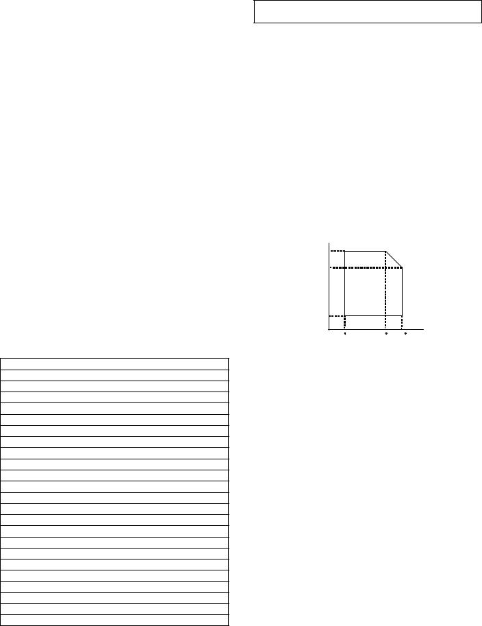
3. Developer/Drum life end definition
When the developer/drum counter reaches the specified level.
When the developer/drum rpm reaches the specified level.
When either of the above reached the specified level, it is judged as life end.
In an actual case, when correction or warm-up operation is performed as well as output operation, the developer and the drum rotates.
Therefore, the developer/drum consuming level cannot be determined only by the copy/print quantity. When, therefore, the rpm reaches the specified level, it is judged as life end.
To check the drum and developer life, use SIM22-1.
|
Developer/drum counter |
Number of rotations |
|
|
(Rotations) |
||
|
|
|
|
|
|
|
|
Developer/drum |
26cpm model |
31cpm model |
550K |
|
|
|
|
|
75K |
100K |
|
|
|
|
|
4. Production number identification
<Toner cartridge> <Drum>
The label on the toner cartridge shows the date of production.
The laser print indicates the model conformity code and the date (year, month, day) of production.
Label position
Internal product name
Incompatibility
Destination
Version No.
Production year/month/day (6 digits) Serial No. in production day (5 digits)
Production place (1 digits)
1 |
2 |
3 |
4 |
5 |
1Alphabet
Indicates the model conformity code. L for this model.
2Number
Indicates the end digit of the production year.
3Number or X, Y, Z
Indicates the month of packing.
X stands for October, Y November, and Z December.
4, 5 Number
Indicates the day of the month of packing.
<Developer>
1 |
2 |
3 |
4 |
5 |
6 |
7 |
8 |
|
|
|
|
|
|
|
|
The lot number is of 8 digits. Each digit indicates the content as follows.
The number is printed on the right under side of the back surface of the developer bag.
1Alphabet
Indicates the production factory.
2Number
Indicates the production year.
3, 4 Number
Indicates the production month.
5, 6 Number
Indicates the production day.
7Hyphen
8Number
Indicates the production lot.
5. Environment conditions
(Humidity)
85%
60%
20%
|
10 C |
30 C |
35 C |
|
||
|
|
|
(Temperature) |
|||
|
|
|
|
|
|
|
Standard environmental |
|
Temperature |
|
20 |
- 25°C |
|
conditions |
|
Humidity |
|
|
65 |
± 5%RH |
Usage environmental |
|
Temperature |
|
10 |
- 35°C |
|
conditions |
|
Humidity |
|
|
20 |
- 85%RH |
|
|
Atmospheric |
|
590 - 1013 hPa |
||
|
|
pressure |
|
|
(height: 0 - 2000m) |
|
Storage period |
|
Toner/Developer: 24 months from the |
||||
|
|
manufactured month (Production lot) |
||||
|
|
under unsealed state |
|
|||
|
|
Drum: 36 months from the manufactured |
||||
|
|
month under unsealed state |
||||
AR-5726/5731 CONSUMABLE PARTS 3 - 3
[4] EXTERNAL VIEW AND INTERNAL STRUCTURE
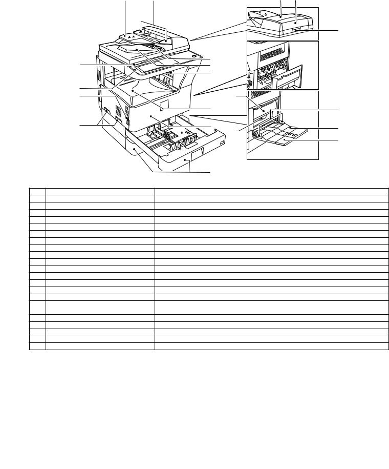
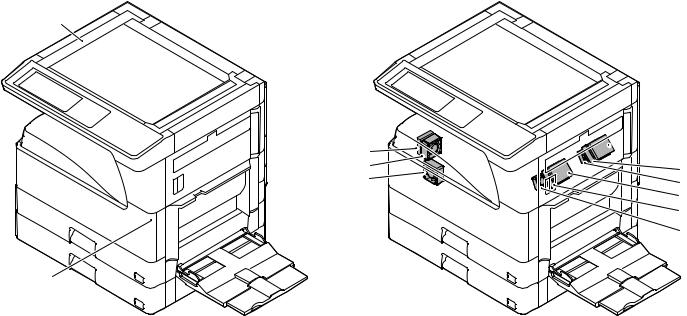
1. External view
1 |
2 |
3 |
6 |
7


 16
16
8 |
4 |
5 |
|
|
12 |
|
11 |
|
|
|
9 |
17 |
|
|
|
13 |
19 |
|
10 |
14 |
20 |
|
|
18 |
|
|
|
|
21 |
|
|
15 |
|
No. |
Name |
Function/Operation |
|
1 |
Document feeder tray |
Place the original(s) that you wish to scan face up here. |
|
2 |
Original guides |
Adjust to the size of the originals. |
|
3 |
Document feeder cover |
Open to remove misfed originals. |
|
4 |
Reversing tray |
Pull out to remove misfed originals. |
|
5 |
Exit area |
Originals exit the machine here after copying. |
|
6 |
Document transport cover |
Open to remove misfed originals. |
|
7 |
Document transport cover knob |
Pull to open the document transport cover. |
|
8 |
Document glass |
Place an original that you wish to scan face down here. |
|
9 |
Power switch |
Press to turn the machine power on and off. |
|
10 |
Handles |
Use to move the machine. |
|
11 |
Operation panel |
Contains operation keys and the touch panel. |
|
12 |
Job separator tray (Upper tray) (optional) |
Print jobs and received faxes are delivered to this tray. |
|
13 |
Center tray |
Finished copies are delivered to the center tray. |
|
14 |
Front cover |
Open to remove paper misfeeds and perform machine maintenance. |
|
15 |
Paper trays |
Each tray holds 500 sheets of copy paper. |
|
16 |
Upper right side cover |
Open to remove misfeeds when an optional job separator tray kit or a optional finisher is |
|
|
|
installed. |
|
17 |
Side cover |
Open to remove misfeeds. |
|
18 |
Side cover handle |
Pull to open the side cover. |
|
19 |
Bypass tray paper guides |
Adjust to the width of the paper. |
|
20 |
Bypass tray |
Regular paper and special paper (such as transparency film) can be fed from the bypass tray. |
|
21 |
Bypass tray extension |
Pull out the bypass tray extension before placing paper in the bypass tray. |
|
AR-5726/5731 EXTERNAL VIEW AND INTERNAL STRUCTURE 4 - 1
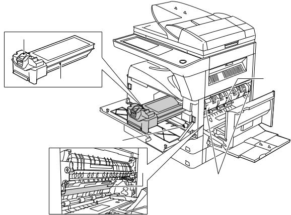
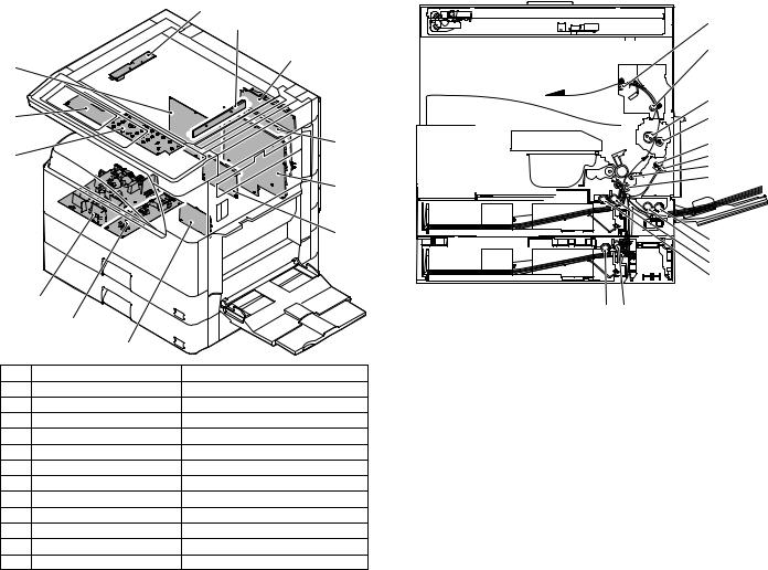
2. Internal structure
1


 6 2
6 2 
3
4
5
No. |
Name |
Function/Operation |
Note |
1 |
Toner cartridge lock release lever |
Use to unlock the toner cartridge. |
|
2 |
Toner cartridge |
Contains toner. |
|
3 |
Roller rotating knob |
Turn to remove misfed paper. |
|
4 |
Photoconductive drum |
Copy images are formed on the photoconductive drum. |
Do not touch the photoconductive |
|
|
|
drum (green portion). Doing so |
|
|
|
may damage the drum and cause |
|
|
|
smudges on copies. |
5 |
Fusing unit release levers |
To remove a paper misfeed in the fusing unit, push up on these |
The fusing unit is hot. |
|
|
levers and remove the paper. |
Do not touch the fusing unit when |
|
|
|
removing misfed paper. |
|
|
|
Doing so may cause a burn or |
|
|
|
injury. |
6 |
Fusing unit paper guide |
Open to remove misfed paper. |
|
AR-5726/5731 EXTERNAL VIEW AND INTERNAL STRUCTURE 4 - 2
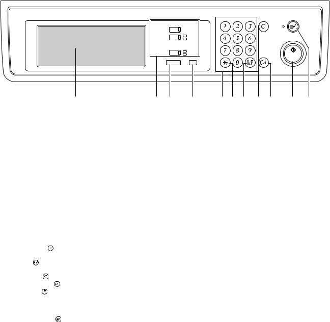
3. Operation panel
COPY |
|
|
ON LINE |
||
DATA |
||
|
||
FAX |
LINE |
|
DATA |
||
|
||
JOB STATUS SYSTEM SETTINGS |
||
|
LOGOUT |
|
|
|
|
1 |
2 |
3 |
4 |
5 |
6 |
7 |
8 |
9 |
10 |
11 |
|
|
|
|
|
|
|
|
|
|
|
|
||
No. |
Name |
|
|
Function/Operation |
|
|
|
|
|
|
Note |
||
1 |
Touch panel |
|
|
The machine status, messages and touch keys are displayed on the panel. |
|
|
|||||||
|
|
|
|
The display will show the status of printing, copying or network scanning |
|
|
|
||||||
|
|
|
|
according to the mode that is selected. For details see the next page. |
|
|
|
||||||
2 |
Mode select keys and indicators |
Use to change modes and the corresponding display on the touch panel. |
|
|
|
||||||||
|
[COPY] key |
|
|
Press to select copy mode. |
|
|
|
|
|
|
|
|
|
|
[PRINT] key/ONLINE indicator/ |
[PRINT] key: Press to select print mode. |
|
|
|
|
|
|
|
|
|||
|
DATA indicator |
|
|
• ONLINE indicator: Print jobs can be received when this indicator is lit. |
|
|
|
||||||
|
|
|
|
• DATA indicator: A print job is in memory. The indicator lights steadily while |
|
|
|||||||
|
|
|
|
the job is held in memory, and blinks while the job is printed. |
|
|
|||||||
|
[FAX] key/LINE indicator/ |
[FAX] key: Press to select fax mode when the fax option is installed. |
|
|
When the fax option is |
||||||||
|
DATA indicator |
|
|
• LINE indicator : This lights up while faxes are being sent or received. |
|
installed. |
|||||||
|
|
|
|
• DATA indicator: Blinks when a fax has been received to memory and lights |
|
|
|||||||
|
|
|
|
steadily when a fax is waiting in memory for transmission. |
|
|
|||||||
3 |
[JOB STATUS] key |
|
Press to display the current job status. |
|
|
|
|
|
|
|
|
||
4 |
[SYSTEM SETTINGS] key |
Use to adjust various settings of the machine including the contrast of the touch |
|
|
|||||||||
|
|
|
|
panel and administrator settings. |
|
|
|
|
|
|
|
|
|
5 |
Numeric keys |
|
|
Use to enter numeric values for various settings. |
|
|
|
|
|
|
|
||
6 |
[LOGOUT] key ( |
) |
|
When auditing mode is enabled, press this key after finishing a job to return the |
|
|
|||||||
|
|
|
|
machine to account number entry standby. |
|
|
|
|
|
|
|
||
7 |
[#/P] key ( ) |
|
|
Use this key to execute a job program in copy mode. |
|
|
|
|
|
|
|
||
|
|
|
|
The key is also used to dial in fax mode. |
|
|
|
|
|
|
|
|
|
8 |
[CLEAR] key ( |
) |
|
Press to clear a copy number setting or cancel a job. |
|
|
|
|
|
|
|
||
9 |
[CLEAR ALL] key ( |
) |
Resets the settings to the initial settings. |
|
|
|
|
|
|
|
|
||
10 |
[START] key ( |
) |
|
Press in copy mode, scanner mode, or fax mode to begin copying, network |
|
|
|||||||
|
|
|
|
scanning, or faxing. |
|
|
|
|
|
|
|
|
|
|
|
|
|
This key blinks when auto power shut mode has activated. Press the key to |
|
|
|||||||
|
|
|
|
return to normal operation. |
|
|
|
|
|
|
|
|
|
11 |
[INTERRUPT] key ( |
) |
Use to perform an interrupt copy job. |
|
|
|
|
|
|
|
|
||
AR-5726/5731 EXTERNAL VIEW AND INTERNAL STRUCTURE 4 - 3
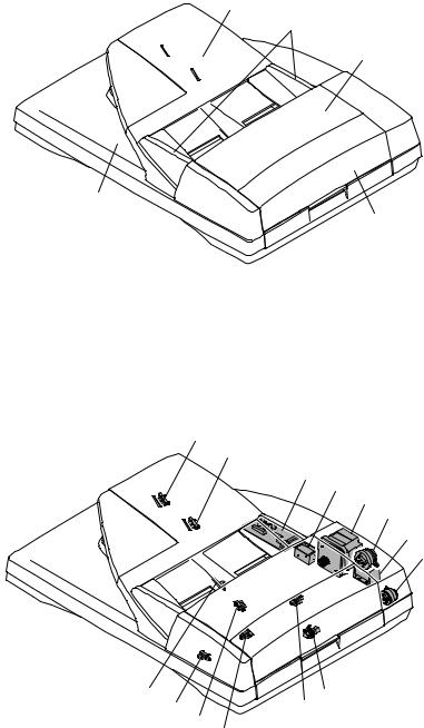
4. RSPF
A. External view
1
2
3
5
4
No. |
Name |
1 |
Document set tray |
|
|
2 |
Document guide |
|
|
3 |
Document feed section cover |
|
|
4 |
Document transport section cover |
|
|
5 |
Document exit section |
|
|
B. Internal structure
11
10
9
8
7
3 5
6
|
|
|
14 |
|
4 |
|
|
|
12 |
13 |
|
|
|
|
1 |
|
|
|
|
|
2 |
|
|
|
|
|
|
|
|
No. |
Code |
Name |
|
Type |
Function/Operation |
|
|
|
|
|
|
1 |
EMPS |
Document set sensor |
|
Photo transmission |
Detects presence of documents. |
|
|
|
|
|
|
2 |
FGOD |
Open/close sensor |
|
Photo transmission |
Detects open/close of the paper feed unit. |
|
|
|
|
|
|
3 |
DFCL |
Paper feed clutch |
|
— |
— |
|
|
|
|
|
|
4 |
DFD |
Paper entry sensor |
|
Photo transmission |
Detects presence of documents. |
|
|
|
|
|
|
5 |
RSOL |
Pressure release solenoid |
|
— |
— |
|
|
|
|
|
|
6 |
CLH |
Transport clutch |
|
— |
— |
|
|
|
|
|
|
7 |
DTM |
SPF motor |
|
Stepping motor |
Drives document feed on the tray, transport, and paper exit roller. |
|
|
|
|
|
|
8 |
GSOL |
Gate solenoid |
|
— |
— |
|
|
|
|
|
|
9 |
— |
Interface PWB |
|
— |
— |
|
|
|
|
|
|
10 |
DLS1 |
Document length detection SW (Short) |
Photo transmission |
Detects the document length on the tray. |
|
|
|
|
|
|
|
11 |
DLS2 |
Document length detection SW (Long) |
Photo transmission |
Detects the document length on the tray. |
|
|
|
|
|
|
|
12 |
OPCLS |
Book sensor |
|
Photo transmission |
Detects the SPF float. |
|
|
|
|
|
|
13 |
RDD |
Paper exit sensor |
|
Photo transmission |
Detects presence of documents. |
|
|
|
|
|
|
14 |
SWD |
Document width sensor |
|
Volume |
Detects the document width on the tray. |
|
|
|
|
|
|
AR-5726/5731 EXTERNAL VIEW AND INTERNAL STRUCTURE 4 - 4
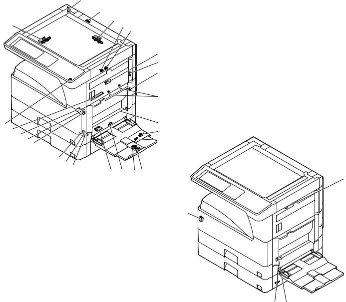
5. Sensor
1
2
3
25 |
4 |
5
6
7
8
9 |

 10
10
24 |
|
|
11 |
23 |
22 |
|
12 |
|
21 |
13 |
|
|
|
||
|
|
20 |
|
|
|
|
|
19 |
|
|
|
|
|
18 |
17 |
|
|
|
|
|
26 |
16 |
15 14 |
|
|
|
|
|||
|
|
|
|
||
No. |
Name |
Code |
Function and operation |
||
1 |
Mirror home position |
MHPS |
Mirror (scanner) home |
||
|
sensor |
|
position detection |
||
2 |
Document cover |
OCSW |
Document cover open/close |
||
|
sensor |
|
detection |
|
|
3 |
Document size |
DSIN3 |
Document size detection |
||
|
sensor |
|
(Inch series: PD3, 4) |
||
|
|
|
(AB series: PD4, 5) |
||
4 |
2nd paper exit sensor |
POD2 |
2nd paper exit detection |
||
|
(Option) |
|
|
|
|
5 |
2nd paper exit full |
TOPF |
2nd paper exit section full |
||
|
detection sensor |
|
detection |
|
|
|
(Option) |
|
|
|
|
6 |
1st paper exit sensor |
POD1 |
1st paper exit detection |
||
7 |
Shifter home position |
SFTHP |
Shifter home position sensor |
||
|
sensor (Except North |
|
detection |
|
|
|
America) |
|
|
|
|
8 |
Paper exit sensor |
PPD2 |
Paper exit detection |
||
|
(DUP side) |
|
|
|
|
9 |
Thermistor |
|
Fusing temperature |
||
|
|
|
detection |
|
|
10 |
1st tray (paper tray) |
CD1 |
1st tray (paper tray) empty |
||
|
detection |
|
detection |
|
|
11 |
Manual feed paper |
PPD1L |
Sensor of paper entry from |
||
|
entry sensor |
|
the manual paper feed tray, |
||
|
|
|
the 2nd/multi-tray desk, or |
||
|
|
|
the DUP |
|
|
12 |
Manual paper feed |
MPLS2 |
Manual feed tray position |
||
|
tray empty sensor 2 |
|
detection |
|
|
13 |
Manual paper feed |
MPLS1 |
Manual feed tray position |
||
|
tray empty sensor 1 |
|
detection |
|
|
14 |
Manual feed length |
MPLD1 |
Manual feed paper length |
||
|
detection sensor 1 |
|
detection |
|
|
15 |
Manual feed length |
MPLD2 |
Manual feed paper length |
||
|
detection sensor 2 |
|
detection |
|
|
16 |
Manual feed paper |
MPED |
Manual feed paper empty |
||
|
empty sensor |
|
detection |
|
|
17 |
2nd tray paper pass |
PFD2 |
2nd tray paper pass |
||
|
sensor |
|
|
|
|
No. |
Name |
Code |
Function and operation |
18 |
2nd tray paper upper |
LUD2 |
2nd tray paper upper limit |
|
limit detection sensor |
|
detection |
19 |
2nd tray paper empty |
PED2 |
2nd tray paper empty |
|
sensor |
|
detection |
20 |
1st tray paper pass |
PPD1H |
1st tray paper pass |
|
sensor |
|
|
21 |
1st tray paper upper |
LUD1 |
1st tray paper upper limit |
|
limit detection sensor |
|
detection |
22 |
1st tray paper empty |
PED1 |
1st tray paper empty |
|
sensor |
|
detection |
23 |
Toner sensor |
|
Toner density detection |
24 |
Center tray paper |
LOEMP |
Center tray paper YES/NO |
|
YES/NO sensor |
|
detection |
25 |
Document size sensor |
DSIN0 |
Document size detection |
|
|
|
(Inch series: PD1, 2) |
|
|
|
(AB series: PD1 – 3) |
26 |
Reverse pass paper |
DUP2 |
Reverse pass detection |
|
detection sensor |
|
|
6. Switch
1
4
|
|
3 |
2 |
|
|
|
|
No. |
Name |
Code |
Function and operation |
1 |
Right cabinet door |
DSWR0 |
Right cabinet door open/ |
|
switch (Option) |
|
close detection |
2 |
Door switch |
DSWR1 |
Front door and side door |
|
|
|
open/close detection |
3 |
2nd right door switch |
DSWR2 |
Side door open/close |
|
|
|
detection |
4 |
Main switch |
PSSW |
Main power switch |
AR-5726/5731 EXTERNAL VIEW AND INTERNAL STRUCTURE 4 - 5
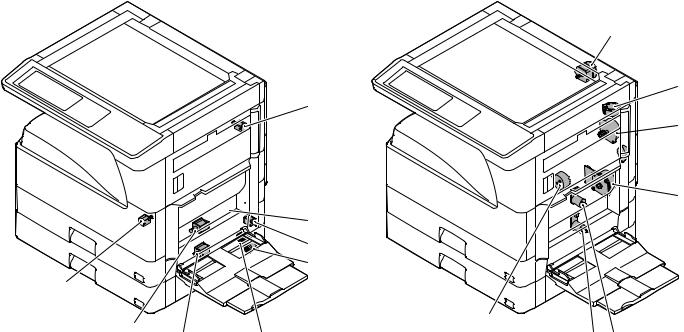
7. Solenoid/Clutch |
8. Drive motor |
1

 2
2
3
4 5
9
|
|
8 |
6 |
|
|
|
7 |
||
|
|
|
|
|
No. |
Name |
|
Code |
Function and operation |
1 |
Paper exit gate |
|
OGS |
Paper exit gate switcher |
|
switching solenoid |
|
|
|
|
(Option) |
|
|
|
2 |
PS clutch |
|
RRC |
Main unit paper feed |
3 |
Paper feed clutch |
|
CPFS1 |
Paper feed roller drive |
4 |
Manual paper feed |
|
MPFS |
Manual paper feed |
|
solenoid |
|
|
solenoid |
5 |
Paper feed transfer |
|
TRC2 |
Paper feed transfer clutch |
|
clutch |
|
|
|
6 |
2nd tray paper feed |
|
CPFS2 |
|
|
clutch |
|
|
|
7 |
2nd tray paper feed |
|
CPFC2 |
Solenoid for the paper feed |
|
solenoid |
|
|
from the tray |
8 |
Paper feed solenoid |
|
CPFC1 |
Solenoid for the paper feed |
|
|
|
|
from the tray |
9 |
Separation pawl |
|
PSPS |
Separation pawl operation |
|
solenoid |
|
|
solenoid |
1
2

 4
4 
 5
5
6 |
|
|
9 |
|
|
|
|
|
|
|
8 |
7 |
|
|
|
|
|
|
No. |
Name |
|
Code |
Function and operation |
|
1 |
Mirror motor |
|
MIRM |
Optical mirror base drive |
|
2 |
Shifter motor |
|
SFTM |
Shifter drive |
|
|
(Except North |
|
|
|
|
|
America) |
|
|
|
|
4 |
Duplex motor |
|
DPXM |
Duplex paper switching |
|
|
|
|
|
and exit motor |
|
5 |
DUP-2 motor |
|
|
Reverse pass for paper |
|
|
|
|
|
transport |
|
6 |
Main motor |
|
MM |
Main drive |
|
7 |
Tray lift-up motor |
|
LUM1 |
Tray paper lift-up |
|
8 |
Tray lift-up motor |
|
LUM2 |
Tray paper lift-up |
|
9 |
Toner motor |
|
TM |
Toner supply |
|
AR-5726/5731 EXTERNAL VIEW AND INTERNAL STRUCTURE 4 - 6
9. Lamp |
10. Fan/Filter |
|
1 |
7 |
2 |
3 |
2


 6
6
1 |
5 |
6 |
1 |
4 |
No. |
Name |
Function and operation |
1 |
Copy lamp |
Image radiation lamp |
2 |
Heater lamp |
Fusing heat lamp |
No. |
Name |
Code |
Function and operation |
1 |
Cooling fan |
VFM |
Cools the inside of the unit. |
2 |
Exhaust fan motor |
DCFM |
Cools the inside of the unit. |
3 |
Intake fan motor |
DCFM2 |
Cools the inside of the unit. |
4 |
Fusing paper exit fan |
VFM2 |
Cools the inside of the unit. |
|
|
|
(31 sheet model) |
5 |
Fusing paper exit fan |
VFM2 |
Cools the inside of the unit. |
6 |
Ozon filter |
|
|
7 |
Ozon filter |
|
|
AR-5726/5731 EXTERNAL VIEW AND INTERNAL STRUCTURE 4 - 7
11. PWB
1
|
|
2 |
12 |
|
3 |
|
|
|
11 |
|
|
10 |
|
4 |
|
|
|
|
|
5 |
|
|
6 |
|
8 |
|
|
9 |
|
|
7 |
|
No. |
Name |
Function and operation |
1 |
Inverter PWB |
Copy lamp control |
2 |
CCD PWB |
For image scanning (read) |
3 |
Option connector PWB |
|
4 |
IMC PWB |
Image process |
5 |
MCU PWB |
Main unit control |
6 |
Mother board |
Connection with FAX PWB |
7 |
Tray interface PWB |
2nd tray control |
8 |
DC power supply PWB |
DC voltage control |
9 |
High voltage PWB |
High voltage control |
10 |
KEY PWB |
|
11 |
OPU PWB |
Operation panel control |
12 |
SPLC PWB |
Output image signal |
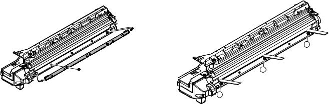
12. Roller
1 |
2 |
3 |
4 |
5 |
6 |
7 |
8 |
9
10
11
12
|
|
14 |
13 |
|
|
|
|
No. |
Name |
|
Function and operation |
1 |
Paper exit roller |
Paper exit roller |
|
2 |
Transport roller |
Paper transport roller |
|
3 |
Upper heat roller |
Fuses toner on paper. |
|
|
|
(with the Teflon roller) |
|
4 |
Lower heat roller |
Fuses toner on paper. |
|
|
|
(with the silicone rubber roller) |
|
5 |
DUP transport follower |
Duplex paper transport |
|
|
roller |
|
|
6 |
DUP transport roller |
Duplex paper transport |
|
7 |
Transport roller |
Transfer images on the drum onto |
|
|
|
paper. |
|
8 |
Resist roller |
Synchronize the paper lead edge |
|
|
|
with the image lead edge. |
|
9 |
Manual paper feed roller |
Picks up papers in manual paper |
|
|
|
feed port. |
|
10 |
Manual feed transport |
Transports paper from the manual |
|
|
roller |
paper feed port. |
|
11 |
1st tray pick-up roller |
Picks up paper from the tray. |
|
12 |
1st tray paper feed roller |
Transports the picked up paper to |
|
|
|
RESIST section. |
|
13 |
2nd tray pick-up roller |
Picks up paper from the tray. |
|
14 |
2nd tray paper feed roller |
Transports the picked up paper to |
|
|
|
RESIST section. |
|
AR-5726/5731 EXTERNAL VIEW AND INTERNAL STRUCTURE 4 - 8
[5] ADJUSTMENTS
1. Adjustment item list
|
Section |
|
Adjustment item |
|
Adjustment procedure/SIM No. |
A |
Process section |
(1) |
Developing doctor gap adjustment |
|
Developing doctor gap adjustment |
|
|
(2) |
MG roller main pole position adjustment |
|
MG roller main pole position adjustment |
|
|
(3) |
Developing bias voltage adjustment |
|
SIM8-1 |
|
|
(4) |
Grid bias voltage adjustment |
|
SIM8-2 |
B |
Mechanism section |
(1) |
Print start position adjustment |
|
SIM50-5 |
|
|
(2) |
RSPF image lead edge position adjustment |
|
SIM50-6 |
|
|
(3) |
Rear edge void adjustment |
|
SIM50-1 |
|
|
(4) |
Paper off center adjustment |
|
SIM50-10 |
|
|
(5) |
Left edge void area adjustment |
|
SIM50-1-8 |
|
|
(6) |
Main scanning direction (FR direction) distortion |
|
No. 2/3 mirror base unit installing position |
|
|
|
balance adjustment |
|
adjustment |
|
|
|
|
|
Copy lamp unit installing position adjustment |
|
|
(7) |
Sub scanning direction (scanning direction) |
|
Winding pulley position adjustment |
|
|
|
distortion adjustment |
|
|
|
|
(8) |
Main scanning direction (FR direction) distortion |
|
Rail height adjustment |
|
|
|
balance adjustment |
|
|
|
|
(9) |
Main scanning direction (FR direction) |
|
SIM48-1-1 |
|
|
|
magnification ratio adjustment |
|
|
|
|
(10) |
Sub scanning direction (scanning direction) |
a |
OC mode in copying (SIM 48-1-2) |
|
|
|
magnification ratio adjustment |
b |
RSPF sub scanning direction magnification ratio |
|
|
|
|
|
(SIM48-1-3, 48-1-4) |
|
|
(11) |
Off center adjustment (RSPF mode) |
|
SIM50-12 |
|
|
(12) |
OC (RSPF) open/close detection position |
|
SIM41-3 |
|
|
|
adjustment |
|
|
|
|
(13) |
Original sensor adjustment |
|
SIM41-2, 41-4 (41-1) |
|
|
(14) |
RSPF white correction pixel position adjustment |
|
SIM63-7 |
|
|
|
(required in an RSPF model when replacing the |
|
|
|
|
|
lens unit) |
|
|
|
|
(15) |
RSPF scan position auto adjustment |
|
SIM53-8 |
C |
Image density |
(1) |
Copy mode |
|
SIM46-2 |
|
(exposure) adjustment |
|
|
|
|
2. Details of adjustment
A. Process section
(1) Developing doctor gap adjustment
1) Remove the doctor cover.
2)Loosen the developing doctor fixing screw A.
3)Insert a thickness gauge of 1.5mm to the positions of three screws on the developing docter as shown.
R
A |
C
A |
F |
A |
4)Tighten the developing doctor fixing screw.
5)Check the clearance of the developing doctor. If it is within the specified range, then fix the doctor fixing screw with screw lock.
When inserting a thickness gauge, be careful not to scratch the developing doctor and the MG roller.
<Adjustment specification>
Developing doctor gap
F/C/R: 1.5 +0.1mm-0.15mm
AR-5726/5731 ADJUSTMENTS 5 - 1
(2) MG roller main pole position adjustment
1)Put the developing unit on a flat surface.
2)Tie a needle or pin on a string.
3)Hold the string and bring the needle close to the MG roller horizontally. (Do not use paper clip, which is too heavy to make a correct adjustment.) (Put the developing unit horizontally for this adjustment.)
4)Do not bring the needle into contact with the MG roller, but bring it to a position 2 or 3mm apart from the MG roller. Mark the point on the MG roller which is on the extension line from the needle tip.
5)Measure the distance from the marking position to the top of the doctor plate of the developing unit to insure that it is 9.1mm.
If the distance is not within the specified range, loosen the fixing screw A of the main pole adjustment plate, and move the adjustment plate in the arrow direction to adjust.
A |
9.1mm
(3) Developing bias voltage adjustment (SIM 8-1)
1) Execute SIM 8-1.
SIMULATION 8-1
2)Touch the exposure mode to be changed. The current set value is displayed.
3)Enter the set value with the 10-key.
4)Press the [START] key.
Output is made with the entered value, and the display returns to the original state.
<Adjustment specification>
|
Item |
Content |
Setting |
Default |
|
|
range |
||||
|
|
|
|
||
|
|
|
|
|
|
1 |
AE (145) |
AE (145mm/s) |
|
450 |
|
|
|
|
|
|
|
2 |
TEXT (145) |
Character |
|
450 |
|
(145mm/s) |
|
||||
|
|
|
|
||
|
|
|
|
|
|
3 |
TEXT/PHOTO |
Character/Photo |
|
450 |
|
(145) |
(145mm/s) |
|
|||
|
|
|
|||
|
|
|
|
|
|
4 |
PHOTO (145) |
Photo (145mm/s) |
|
450 |
|
|
|
|
|
|
|
5 |
TONER SAVE |
Toner save |
|
400 |
|
(145) |
(145mm/s) |
200- |
|||
|
|
||||
|
|
|
650 |
|
|
6 |
AE (122) |
AE (122mm/s) |
450 |
||
|
|
|
|
|
|
7 |
TEXT (122) |
Character |
|
450 |
|
(122mm/s) |
|
||||
|
|
|
|
||
|
|
|
|
|
|
8 |
TEXT/PHOTO |
Character/Photo |
|
450 |
|
(122) |
(122mm/s) |
|
|||
|
|
|
|||
|
|
|
|
|
|
9 |
PHOTO (122) |
Photo (122mm/s) |
|
450 |
|
|
|
|
|
|
|
10 |
TONER SAVE |
Toner save |
|
400 |
|
(122) |
(122mm/s) |
|
|||
|
|
|
|||
|
|
|
|
|
Min. unit: –10V increment
(4) Grid bias voltage adjustment (SIM 8-2)
1) Execute SIM 8-2.
SIMULATION 8-2
2)Touch the exposure mode to be changed. The current set value is displayed.
3)Enter the set value with the 10-key.
4)Press the [START] key.
Output is made with the entered value for 30sec, and the display returns to the original state.
<Adjustment specification>
|
|
Item |
|
|
Content |
Setting |
|
|
Default |
|||
|
|
|
|
range |
|
|
||||||
|
|
|
|
|
|
|
|
|
|
|
||
|
|
|
|
|
|
|
|
|
|
|
|
|
1 |
|
AE (145) |
|
AE (145mm/s) |
|
|
|
|
590 |
|||
|
|
|
|
|
|
|
|
|
|
|
|
|
2 |
|
TEXT (145) |
|
Character |
|
|
|
|
590 |
|||
|
|
(145mm/s) |
|
|
|
|
||||||
|
|
|
|
|
|
|
|
|
|
|
||
|
|
|
|
|
|
|
|
|
|
|
|
|
3 |
|
TEXT/PHOTO |
|
Character/Photo |
|
|
|
|
590 |
|||
|
(145) |
|
|
|
(145mm/s) |
|
|
|
|
|||
|
|
|
|
|
|
|
|
|
|
|||
|
|
|
|
|
|
|
|
|
|
|
|
|
4 |
|
PHOTO (145) |
|
Photo (145mm/s) |
|
|
|
|
590 |
|||
|
|
|
|
|
|
|
|
|
|
|
|
|
5 |
|
TONER SAVE |
|
Toner save |
|
|
|
|
540 |
|||
|
(145) |
|
|
|
(145mm/s) |
350- |
|
|
|
|||
|
|
|
|
|
|
|
|
|
||||
|
|
|
|
|
|
|
|
750 |
|
|
|
|
6 |
|
AE (122) |
|
AE (122mm/s) |
|
|
590 |
|||||
|
|
|
|
|
|
|
|
|
|
|
|
|
7 |
|
TEXT (122) |
|
Character |
|
|
|
|
590 |
|||
|
|
(122mm/s) |
|
|
|
|
||||||
|
|
|
|
|
|
|
|
|
|
|
||
|
|
|
|
|
|
|
|
|
|
|
|
|
8 |
|
TEXT/PHOTO |
|
Character/Photo |
|
|
|
|
590 |
|||
|
(122) |
|
|
|
(122mm/s) |
|
|
|
|
|||
|
|
|
|
|
|
|
|
|
|
|||
|
|
|
|
|
|
|
|
|
|
|
|
|
9 |
|
PHOTO (122) |
|
Photo (122mm/s) |
|
|
|
|
590 |
|||
|
|
|
|
|
|
|
|
|
|
|
|
|
10 |
|
TONER SAVE |
|
Toner save |
|
|
|
|
540 |
|||
|
(122) |
|
|
|
(122mm/s) |
|
|
|
|
|||
|
|
|
|
|
|
|
|
|
|
|||
|
|
|
|
|
|
|
|
|
|
|
|
|
Min. unit: –10V increment |
|
|
|
|
|
|
|
|||||
B. Mechanism section |
|
|
|
|
|
|||||||
(1) Print start position adjustment |
|
|
|
|
|
|||||||
1) |
Execute SIM 50-5. |
|
|
|
|
|
|
|
||||
|
|
|
|
|
|
|
|
|
|
|
|
|
|
|
|
|
SIMULATION 50-5 |
|
|
|
|
|
|
|
|
|
|
|
|
LEAD EDGE ADJUSTMENT(PRINT). INPUT VALUE 0-99, AND PRESS |
|
|||||||
|
|
|
|
START. |
|
|
|
|
|
|
|
|
|
|
|
|
|
|
|
|
|
|
|
||
|
|
|
|
1: TRAY1 |
53 |
|
|
53 |
|
|
||
|
|
|
|
2: OPTION |
53 |
|
1/1 |
|
|
|||
|
|
|
|
3: MANUAL |
53 |
|
|
|
|
|
|
|
|
|
|
|
4: DUPLEX |
53 |
|
|
|
|
|
|
|
|
|
|
|
|
|
|
|
|
|
|
|
|
|
|
|
|
|
|
|
|
|
|
|
|
|
2)Touch the item to be adjusted.
The item and the currently set value are highlighted.
3)Press the [P] key.
The display is shifted to the copy menu.
4)Select the paper feed tray, the print density, and the duplex mode. Enter the adjustment value with the 10-key.
5)Press the [START] key. Copying is started.
AR-5726/5731 ADJUSTMENTS 5 - 2
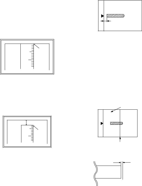
|
Item |
Content |
Setting range |
Default |
|
1 |
TRAY1 |
1st tray |
0-99 |
|
|
2 |
OPTION |
Option tray |
|
53 |
|
3 |
MANUAL |
Manual feed |
1-99 |
||
|
|||||
4 |
DUPLEX |
Back print |
|
|
6)Measure the distance H between the paper lead edge and the image print start position. Set the image print start position set value again.
•1 step of the set value corresponds to about 0.127mm shift.
•Calculate the set value from the formula below.
99 – H/0.127 (mm) = Image print start position set value <H: Print start position measurement value (mm)>
0mm |
0mm |
5 |
10 |
Fit the print edge with the paper edge, and perform the lead edge adjustment.
Example:99 – 5/0.127 = 99 – 39.4 = about 59
Note: FIf the set value is not obtained from the above formula, perform the fine adjustment.
7)Execute SIM 50-1-2 to adjust the main tray lead edge void.
•1 step of the set value corresponds to about 0.127mm shift.
•Calculate the set value from the formula below. B/0.127 (mm) = Lead edge void adjustment value <B: Lead edge void (mm)>
2.5mm |
5 |
2.5mm |
10 |
Example: When setting the lead edge void to 2.5mm: 2.5 /0.127 = about 20
<Adjustment specification>
Adjustment |
SIM |
Set value |
Spec value |
Setting |
|
mode |
range |
||||
|
|
|
|||
Main tray lead |
50-1 |
B/0.127 |
Lead edge void: |
|
|
edge void |
-2 |
|
1 – 4mm |
1 – 99 |
|
Print start |
50-5 |
99 – H/0.127 |
Image loss: 3mm |
||
|
|||||
position |
|
|
or less |
|
[H: Print start position measurement value (mm), B: Lead edge void (mm)]
(2) RSPF image lead edge position adjustment
1) Set a scale on the OC table as shown below.
Note: Since the printed copy is used as a test chart, put the scale in paralleled with the edge lines.
2)Make a copy, then use the copy output as an original to make an RSPF copy again.
3)Check the copy output. If necessary, perform the following adjustment procedures.
4)Execute SIM 50-6.
5)Set the RSPF lead edge position set value so that the same image is obtained as that obtained in the previous OC image lead edge position adjustment.
<Adjustment specification>
Adjustment |
SIM |
Set value |
Spec value |
Setting |
|
mode |
range |
||||
|
|
|
|||
RSPF |
50-6 |
1 step: |
Lead edge void: |
|
|
image lead |
|
0.127mm |
1 – 4mm |
1 – 99 |
|
edge |
|
shift |
Image loss: 3mm or less |
||
|
|
||||
position |
|
|
|
|
(3) Rear edge void adjustment
1) Set a scale as shown in the figure below.
A4 (8.5" x 11") |
Paper rear edge
2)Set the document size to A4 (8.5" x 11"), and make a copy at 100%.
3)If an adjustment is required, follow the procedures below.
Void amount (Standard value: 4mm or less)
Scale image
 Paper rear edge
4)Execute SIM 50-1 and set the density mode to DEN-B. The currently set adjustment value is displayed.
5)Enter the set value and press the start key.
The correction value is stored and a copy is made.
<Adjustment specification>
Adjustment |
SIM |
Set value |
Spec |
Setting |
|
mode |
value |
range |
|||
|
|
||||
Rear edge |
50-1-6 |
1 step: 0.127mm |
4mm or |
1 – 99 |
|
void |
shift |
less |
|
||
|
|
AR-5726/5731 ADJUSTMENTS 5 - 3

(4) Paper off center adjustment
1)Set a test chart (UKOG-0089CSZZ) on the document table.
2)Select a paper feed port and make a copy.
3)Execute SIM 50-10.
SIMULATION 50-10
PRINT OFF-CENTER ADJUSTMENT. INPUT VALUE 1-99, AND
PRESS START.
1: BYPASS |
50 |
|
50 |
2: TRAY1 |
50 |
1/1 |
|
3: TRAY2 |
50 |
|
|
4: TRAY3 |
50 |
|
|
5: TRAY4 |
50 |
|
|
6: DUPLEX |
50 |
|
OK |
|
|
|
|
4)Touch the item to be adjusted.
The item and the currently set value are highlighted.
5)Press the [START] key.
The display is shifted to the copy menu.
6)Select the paper feed tray and the print density. Enter the adjustment value with the 10-key.
7)Press the [START] key. Copying is started.
|
Item |
|
|
Content |
Setting range |
|
Default |
|
1 |
BYPASS |
|
Manual paper feed |
|
|
|
|
|
2 |
TRAY1 |
|
1st tray |
|
|
|
|
|
3 |
TRAY2 |
|
2nd tray |
1-99 |
50 |
|||
4 |
TRAY3 |
|
3rd tray |
|||||
|
|
|
|
|
||||
5 |
TRAY4 |
|
4th tray |
|
|
|
|
|
6 |
DUPLEX |
|
Back print |
|
|
|
|
|
<Adjustment specification> |
|
|
|
|
||||
|
|
|
|
|
|
|
|
|
Adjustment |
|
SIM |
Set value |
|
Spec value |
|
Setting |
|
|
mode |
|
|
|
range |
|||
|
|
|
|
|
|
|
||
Paper off |
50-10 |
Add 1: 0.127mm |
|
Single: |
|
|
||
center |
-2 |
shift to R side. |
|
Center |
|
|
||
|
|
|
|
Reduce 1: |
|
±2.0mm |
|
1 – 99 |
Second |
50-10 |
0.127mm shift to L |
|
Duplex: |
|
|||
|
|
|
||||||
print surface |
-6 |
side. |
|
Center |
|
|
||
off-center |
|
|
|
|
±2.5mm |
|
|
|
(5) Left edge void area adjustment
Note: Before performing this adjustment, be sure to check that the paper off center adjustment (SIM 50-10) is completed.
1) Execute SIM 50-1.
SIMULATION 50-1
LEAD EDGE ADJUSTMENT. INPUT VALUE 1-99, AND PRESS START.
1: RRC-A |
43 |
2: DEN-A |
18 |
43 |
3: DEN-A -MANUAL |
18 |
4: DEN-A -OPTION |
18 |
|
5: DEN-A -DUPLEX |
18 |
6: DEN-B |
3 |
1/1 |
7: DEN-B-DUP |
50 |
8: SIDE VOID |
18 |
|
9: SIDE VOID-DUP |
18 |
10: LOSS(OC) |
3 |
|
OK
2)Note down the adjustment value of SIM 50-5 (Items 1, 2, 3, 4), and change the value to 99.
3)Set SIM 50-1 (Items 2, 3, 4, 5) to 1. (By setting to 1, there is no void.)
4)Place a chart with a clear lead edge (or a ruler) on the OC document table.
5)Use SIM 50-1 (Item 1) to execute test print. Check the print out and adjust so that the lead edge image is printed. (1 – 99: About 0.127mm/Step)
6)Reset the adjustment values of SIM 50-5 (Items 1, 2, 3, 4) to the original values, and execute test print. Check the print out and adjust so that the lead edge image is printed on the lead edge of paper. (1 – 99: About 0.127mm/Step).
7)Adjust SIM 50-1 (Items 2, 3, 4, 5) so that the lead edge void on the print out is the specified value. (1 – 99: About 0.127mm/Step)
8)Similar to procedure 7, adjust SIM 50-1 (Item 6, 7) so that the rear edge void is the specified value. (1 – 99: About 0.127mm/Step)
9)Similar to procedure 7, adjust SIM 50-1 (Item 8, 9) so that the left edge void is the specified value. (1 – 99: About 0.127mm/Step)
10)Make an enlargement copy (400%), and check that there is no shade of the cabinet printed at the lead edge.
11)If there is a shade printed at the lead edge in procedure 9, adjust SIM 50-1 (Item 10). (1 – 5: About 0.677mm)
*If there is no problem, set to 3.
|
Item |
|
|
Content |
|
|
Setting |
Default |
|
|
|
|
|
|
|
|
|
range |
|
1 |
RRC-A |
|
Original scan start position |
|
1-99 |
43 |
|||
|
|
|
|
adjustment |
|
|
|
|
|
|
|
|
|
Lead edge position |
|
|
|
|
|
|
|
|
|
adjustment value (OC) |
|
|
|
|
|
2 |
DEN-A |
|
Lead edge cancel |
|
|
1-99 |
18 |
||
|
|
|
|
adjustment (Main tray) |
|
|
|
|
|
3 |
DEN-A-MANUAL |
Lead edge cancel |
|
|
1-99 |
18 |
|||
|
|
|
|
adjustment |
|
|
|
|
|
|
|
|
|
(Manual feed tray) |
|
|
|
|
|
4 |
DEN-A-OPTION |
Lead edge cancel |
|
|
1-99 |
18 |
|||
|
|
|
|
adjustment (Option tray) |
|
|
|
|
|
5 |
DEN-A-DUPLEX |
Lead edge cancel |
|
|
1-99 |
18 |
|||
|
|
|
|
adjustment |
|
|
|
|
|
|
|
|
|
(back of the machine) |
|
|
|
|
|
6 |
DEN-B |
|
Rear edge void adjustment |
|
1-99 |
30 |
|||
7 |
DEN-B-DUP |
|
Rear edge void adjustment |
|
1-99 |
50 |
|||
|
|
|
|
(Duplex) |
|
|
|
|
|
8 |
SIDE VOID |
|
Left edge void adjustment |
|
1-99 |
18 |
|||
|
|
|
|
(First print surface) |
|
|
|
|
|
9 |
SIDE VOID-DUP |
Left edge void adjustment |
|
1-99 |
18 |
||||
|
|
|
|
(Duplex) |
|
|
|
|
|
10 |
LOSS(OC) |
|
Image loss amount |
|
|
1-5 |
3 |
||
|
|
|
|
adjustment (Lead edge |
|
|
|
|
|
|
|
|
|
image loss set value) (OC) |
|
|
|
||
<Adjustment specification> |
|
|
|
|
|||||
|
|
|
|
|
|
|
|
||
Adjustment |
|
SIM |
|
Set value |
|
Spec |
Setting |
||
|
mode |
|
|
|
value |
range |
|||
|
|
|
|
|
|
||||
Left edge void |
50-1 |
|
1 step: 0.127mm |
0.5 – 4mm |
1 – 99 |
||||
|
|
|
-8 |
|
shift |
|
|
|
|
AR-5726/5731 ADJUSTMENTS 5 - 4

(6)Main scanning direction (FR direction) distortion balance adjustment
1) Remove the OC glass, the right cabinet and the upper right side cover.
|
1 |
|
3 |
|
1 |
|
|
|
1 |
|
|
|
1 |
2 |
|
|
6 |
5
4
4
2) Loosen the copy lamp unit wire fixing screw.
Wire fixing screw
3)Manually turn the mirror base drive pulley and bring No. 2/3 mirror base unit into contact with the positioning plate.
At that time, if the front frame side and the rear frame side of No. 2/ 3 mirror base unit are brought into contact with the positioning plate at the same time, the mirror base unit parallelism is proper.
If one of them is in contact with the positioning plate, perform the adjustment of 4).
5)Without moving the scanner drive pulley shaft, manually turn the scanner drive pulley until the positioning plate is brought into contact with No. 2/3 mirror base unit, then fix the scanner drive pulley.
6)Put No. 2/3 mirror base unit on the positioning plate again, push the projections on the front frame side and the rear frame side of the copy lamp unit to the corner frame, and tighten the wire fixing screw.
(7)Sub scanning direction (scanning direction) distortion adjustment (Winding pulley position adjustment)
This adjustment must be performed in the following cases:
•When the mirror base drive wire is replaced.
•When the lamp unit, or No. 2/3 mirror holder is replaced.
•When a copy as shown is made.
La |
Lb |
Paper exit direction
Original |
Copy |
4)Loosen the set screw of the scanner drive pulley which is not in contact with No. 2/3 mirror base unit positioning plate.
AR-5726/5731 ADJUSTMENTS 5 - 5

1)Set A3 (11" x 17") white paper on the original table as shown below.
Place a little clearance from |
|
the rear side original guide. |
|
Glass holding plate |
A3 (11" x 17") white paper |
Fit the paper edge and
the glass holding plate edge.
2)Open the original cover and make a normal (100%) copy.
3)Measure the width of the black background at the lead edge and at the rear edge.
Paper exit direction
La: Lead edge black background width
Lb: Rear edge black background width
If the width (La) of the black background at the lead edge is equal that (Lb) at the rear edge, there is no need to execute the following procedures of 4) – 7).
4)Loosen the mirror base drive pulley fixing screw on the front frame side or on the rear frame side.
•When La < Lb
Turn the mirror base drive pulley on the front frame side in the arrow direction A. (Do not move the mirror base drive pulley shaft.)
•When La > Lb
Turn the mirror base drive pulley on the rear frame side in the arrow direction A. (Do not move the mirror base drive pulley shaft.)
Rear side
A
B
Front side
5) Tighten the fixing screw of the mirror base drive pulley.
<Adjustment specification>
La = Lb
6)Execute the main scanning direction (FR) distortion balance adjustment previously described in 2) again.
(8)Main scanning direction (FR direction) distortion balance adjustment (Rail height adjustment)
When there is no skew copy in the mirror base scanning direction and there is no horizontal error (right angle to the scanning direction), the adjustment can be made by adjusting the No. 2/3 mirror base unit rail height.
Before performing this adjustment, be sure to perform the horizontal image distortion adjustment in the laser scanner section.
This adjustment must be performed in the following cases:
•When the mirror base wire is replaced.
•When the copy lamp unit and no. 2/3 mirror unit are replaced.
•When the mirror unit rail is replaced and moved.
•When a following copy is made.
Original |
Copy A |
Copy B |
1)Make an original for the adjustment.
Make test sheet by drawing parallel lines at 10mm from the both ends of A3 (11" x 17") white paper as shown below. (These lines must be correctly parallel to each other.)
Parallel line |
Parallel line |
10mm |
10mm |
10mm |
10mm |
White paper
2)Make a normal (100%) copy of the test sheet on A3 (11" x 17") paper. (Fit the paper edge and the glass holding plate edge.)
3)Measure the distances (La, Lb, Lc, Ld) at the four corners as shown below.
La |
Lc |
Paper exit direction
Lb |
Ld |
When La = Lb and Lc = Ld, no need to perform the procedures 4) and 5).
AR-5726/5731 ADJUSTMENTS 5 - 6
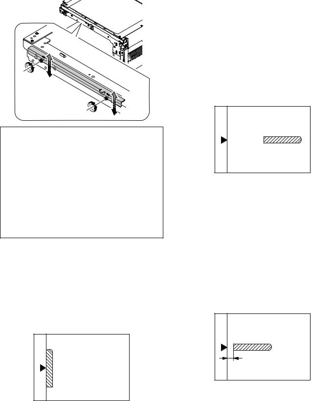
4)Move the mirror base B rail position up and down (in the arrow direction) to adjust.
•When La > Lb
Shift the mirror base B rail upward by the half of the difference of La–Lb.
•When La < Lb
Shift the mirror base B rail downward by the half of the difference of Lb–La.
Example: When La = 12mm and Lb = 9mm, shift the mirror base B rail upward by 1.5mm.
•When Lc >Ld
Shift the mirror base B rail downward by the half of the difference of Lc–Ld.
•When Lc < Ld
When Lc < Ld, move the mirror base B on the paper feed side upward.
When moving the mirror base rail, hold the mirror base rail with your hand.
<Adjustment specification>
La = Lb, Lc = Ld
5)After completion of adjustment, manually turn the mirror base drive pulley, scan the mirror base A and mirror base B fully, and check that the mirror bases are not in contact with each other.
If the mirror base rail is moved extremely, the mirror base may be in contact with the frame or the original glass. Be careful to avoid this.
(9)Main scanning direction (FR direction) magnification ratio adjustment (SIM 48-1)
Note: Before performing this adjustment, be sure to check that the CCD unit is properly installed.
1) Put a scale on the original table as shown below.
2)Execute SIM 48-1.
3)After warm-up, shading is performed and the current set value of the main scanning direction magnification ratio is displayed on the display section in 2 digits.
4)Manual correction mode (SIM48-1-1) Enter the set value and press the start key.
The correction value is stored and a copy is made.
AR-5726/5731
<Adjustment specification>
Note: A judgment must be made with 200mm width, and must not be made with 100mm width.
Adjustment |
Spec value |
SIM |
Set value |
Setting |
|
mode |
range |
||||
|
|
|
|||
Main scanning |
At normal: |
48- |
Add 1: 0.1% |
1 – 99 |
|
direction |
±1.0% |
1-1 |
increase |
|
|
magnification |
|
|
Reduce 1: 0.1% |
|
|
ratio |
|
|
decrease |
|
(10)Sub scanning direction (scanning direction) magnification ratio adjustment
(SIM 48-1-2, SIM 48-1-3)
a. OC mode in copying
Note: Execute the procedure after completion of SIM 48-1-1.
1)Put a scale on the original table as shown below, and make a normal (100%) copy.
2)Compare the scale image and the actual scale.
If necessary, perform the following adjustment procedures.
3)Execute SIM 48-1-2.
4)Enter the set value and press the start key. The set value is stored and a copy is made.
<Adjustment specification>
Adjustment |
Spec value |
SIM |
|
Set value |
|
Setting |
mode |
|
|
range |
|||
|
|
|
|
|
||
Sub scanning |
At normal: |
48-1- |
|
Add 1: |
|
1 – 99 |
direction |
±1.0% |
2 |
|
0.05% increase |
|
|
magnification |
|
|
|
Reduce 1: |
|
|
ratio (OC mode) |
|
|
|
0.05% decrease |
|
|
b. RSPF mode in copying |
|
|
|
|
|
|
Note: Before performing this adjustment, |
be sure to check |
that the |
||||
CCD unit is properly installed and that OC mode adjustment in copying has been completed.
1)Put a scale on the original table as shown below, and make a normal (100%) copy to make a test chart.
Note: Since the printed copy is used as a test chart, put the scale in parallel with the front side edge of the glass.
2)Set the test chart on the RSPF and make a normal (100%) copy.
3)Compare the scale image and the actual image.
If necessary, perform the following adjustment procedures.
4)Execute SIM 48-1-3.
5)After warm-up, shading is performed.
The current front surface sub scanning direction magnification ratio correction value is displayed in two digits on the display section.
ADJUSTMENTS 5 - 7
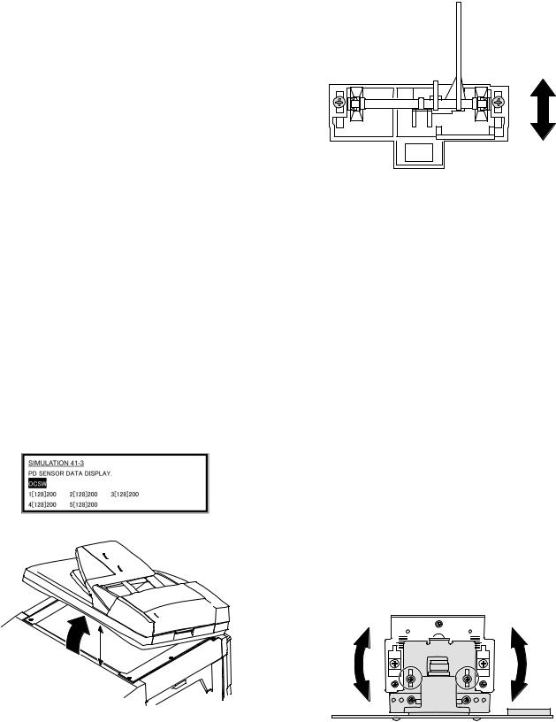
6)Enter the set value and press the start key. The set value is stored and a copy is made.
7)Execute SIM 48-1-4.
The current back surface sub scanning direction magnification ratio is displayed in two digits on the display section.
8)Enter the set value and press the start key. The set value is stored and a copy is made.
<Adjustment specification>
Adjustment mode |
Spec |
SIM |
Set value |
Setting |
|
value |
range |
||||
|
|
|
|||
Sub scanning |
At normal: |
48-1-3 |
Add 1: |
1 – 99 |
|
direction |
±1.0% |
48-1-4 |
0.05% increase |
|
|
magnification ratio |
|
|
Reduce 1: |
|
|
(RSPF mode) |
|
|
0.05% decrease |
|
(11) Off center adjustment (RSPF mode)
Note: Before performing this adjustment, be sure to check that the paper off center is properly adjusted.
1)Place the center position adjustment test chart (sheet with a straight line in the scan direction at the center) on the RSPF.
2)Make a normal copy from the manual paper feed tray, and check the printed copy with the test chart.
If any adjustment is required, perform the following procedure.
3)Execute SIM 50-12.
4)After warm-up, shading is performed and the current set value of the off center adjustment is displayed on the display section in 2 digits.
5)Enter the set value and press the start key. The set value is stored and a copy is made.
<Adjustment specification>
Adjustment |
Spec value |
SIM |
Set value |
Setting |
||
mode |
range |
|||||
|
|
|
||||
Original off |
Single: Center |
50-12 |
Add 1: 0.1mm |
1 – 99 |
||
center mode |
± 3.0mm |
|
shift to R side |
|
||
(RSPF |
|
Duplex: Center |
|
Reduce 1: 0.1mm |
|
|
mode) |
±3.5mm |
|
shift to L side |
|
||
(12) OC (RSPF) open/close detection position adjustment
1)Execute SIM 41-3.
2)Gradually close the OC (RSPF) from the full open position, and measure distance A when the display on the operation panel changes. (See the figure below.)
Distance A = Table glass top - OC (RSPF) handle rib
A
<Adjustment specification>
OC (SPF) open/close position A: 125 – 225mm
3)If the distance is outside the specified range, adjust the open/close sensor attachment plate position as shown below.
Distance < 125mm: Shift toward A.
Distance > 225mm: Shift toward B.
A
B
(13) Original sensor adjustment (SIM 41-2, 41-4)
1)Set A3 (11" x 17") paper on the OC table. (Keep the SPF (OC cover) open.)
2)Execute SIM 41-2.
3)Keep A=125mm, and execute SIM 41-4. (Do not put paper on the table.)
4)Check the reaction with SIM 41-1.
(14)RSPF white correction pixel position adjustment (required in an RSPF model when replacing the lens unit) (SIM63-7)
1)Fully open the RSPF.
2)Execute SIM 63-7.
3)When the operation panel displays "COMPLETE," the adjustment is completed.
4)If the operation panel displays "ERROR," perform the following measures.
•When the display is 0: Check that the SPF is open.
Check that the lamp is ON. (If the lamp is OFF, check the MCU connector.)
Check that the CCD harness is properly inserted into the MCU connector.
•When the display is 281 or above:
1)Remove the table glass.
2)Remove the dark box.
3)Slide the lens unit toward the front side and attach it, then execute SIM.
•When the display is 143 or below:
1)Remove the table glass.
2)Remove the dark box.
3)Slide the lens unit toward the rear side and attach it, then execute SIM.
F R
When the lens unit is moved, execute the OC main scanning magnification ratio auto adjustment, SIM 48-1-1.
This adjustment is basically O.K. with SIM 63-7.
AR-5726/5731 ADJUSTMENTS 5 - 8
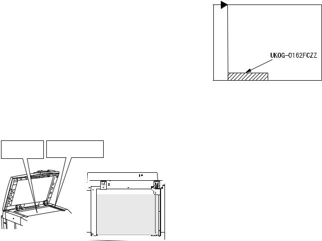
(15) RSPF scan position auto adjustment
[Function]
Used to adjust the RSPF scan position automatically.
[Operation]
1)With the RSPF or the OC cover open, place a white paper background on the OC glass. (In the RSPF standard model, the RSPF glass surface is included.)
2)Enter SIM53-08, and press [START] button.
Outline of SIM: The optical unit is shifted to recognize the boundary between the OC glass and the RSPF glass cover.
With the same position as the reference, the RSPF scan position is automatically adjusted.
<Note>
•After completion of the RSPF scan position auto adjustment, the RSPF lead edge adjustment must be executed. (Both surfaces)
•There must be no other sheet than the black chart on the glass surface.
•Especially when in RSPF scan, the center area is scanned in the main scan direction. Be careful to prevent external light from entering the scan area.
3)Check that the lead edge is not shifted. (Both surfaces)
(If the original lead edge adjustment has been made properly, even when the scan position is shifted, it is followed automatically.)
Place only the white |
For the RSPF standard-provision |
|||
machine, check that the white |
||||
paper on the OC glass. |
||||
paper covers the SPF glass. |
||||
|
|
|||
|
|
|
|
|
|
|
|
|
|
Placing the white paper
The white chart must cover this area.
C. Image density (exposure) adjustment
(1) Copy mode (SIM46-2)
1)Set a test chart (UKOG-0162FCZZ) on the OC table as shown below.
Rear
Front
2)Place three or more sheets of A3 (11" x 17") paper on the test chart.
3)Execute SIM 46-2.
4)After warm-up, shading is performed and the current set value of the density (exposure) level is displayed on the display section in 2 digits.
For mode selection, use the [10-key].
5)Change the set value with the [10-key] to adjust the copy image density.
6)Make a copy and check that the specification below is satisfied.
Note: Place originals in the rear reference, and the test chart in the front reference when adjusting the exposure.
<Adjustment specification>
Density mode |
Exposure |
Sharp Gray |
Set value |
Setting |
|
level |
Chart output |
range |
|||
|
|
||||
|
|
|
|
|
|
AUTO |
– |
"3" is copied. |
If too bright, |
|
|
|
|
|
increase the |
|
|
TEXT |
3.0 |
"3" is copied. |
|
||
quantity displayed |
|
||||
|
|
|
|
||
TEXT/PHOTO |
3.0 |
"3" is copied. |
|
||
on the copy |
|
||||
|
|
|
|
||
PHOTO |
3.0 |
"2" is copied. |
quantity display. |
|
|
|
|
|
If too dark, |
1 – 99 |
|
AE |
– |
"3" is copied. |
|||
(TONER SAVE) |
decrease the |
|
|||
|
|
|
|||
|
|
|
quantity displayed |
|
|
TEXT |
3.0 |
"3" is copied. |
|
||
on the copy |
|
||||
(TONER SAVE) |
|
||||
|
|
quantity display. |
|
||
|
|
|
|
||
TEXT PHOTO |
3.0 |
"3" is copied. |
|
||
|
|
||||
(TONER SAVE) |
|
|
|||
|
|
|
|
||
|
|
|
|
|
AR-5726/5731 ADJUSTMENTS 5 - 9
[6] SIMULATION
1. General
A. Outline and purpose
The simulation has the following functions to grasp the machine operating status, identify the trouble position and causes in an earlier stage, and make various setups and adjustments speedily for improving the serviceability of the machine.
1)Various adjustments
2)Setup of specifications and functions
3)Canceling troubles
4)Operation check
5)Various counters check, setup, and clear
6)Machine operating status (operation history) data check, clear
7)Transfer of various data (adjustments, setup, operations, counters)
The operating procedures and the displays differ depending on the form of the operation panel of the machine.
B. Code-type simulation
(1) Operating procedures and operations
* Entering the simulation mode
1)#/P key (program) ON → Asterisk (*) key ON → CLEAR key ON → Asterisk (*) key ON → Ready for input of a main code of simulation
2)Entering a main code with the 10-key → START key ON
3)Entering a sub code with the 10-key → START key ON
4)Select an item with the scroll key and the item key.
5)The machine enters the mode corresponding to the selected item. Press START key to start the simulation operation.
To cancel the current simulation mode or to change the main code and the sub code, press the SYSTEM SETTINGS key.
* Canceling the simulation mode to return to the normal mode
1) Press CLEAR ALL key.
(2)How to change the simulation adjustment value set by the touch panel in the adjustment value entry process
a. Target SIM list
3-7, 8-1, 8-2, 8-3, 8-10, 8-11, 8-12, 9-5, 43-1, 44-34, 46-2, 46-9, 46-10, 46-11, 46-18, 46-20, 46-30, 46-31, 48-1, 48-2, 50-1, 50-5, 50-6, 50-10, 50-12, 51-1, 51-2, 51-9, 53-7
b. Touch panel operating procedure
•In the adjustment value setup menu, the selected item is highlighted. Change is made to the highlighted simulation adjustment value.
•If all the list of the adjustment items is not shown on one page, touch [↑] and [↓] button to shift the page.
•To change an adjustment value, touch the select the item to change the adjustment value. (The selected item is highlighted.) Enter the adjustment value and perform one of the following procedures, and the display of the adjustment value of the selected item is renewed as well as the adjustment value.
1)Touch [OK] button.
2)Touch another selected item to change the selection state.
3)If all the list of the adjustment items cover two or more pages, touch [↑] and [↓] button to shift the page.
4)Press [START] key.
*For simulations which allow confirmation print, copying is started after changing the adjustment value.
(46-2, 46-9, 46-10, 46-11, 46-18, 48-1, 48-2, 50-1, 50-5, 50-6, 50-10, 50-12, 51-2, the bold-faced items in the above list.)
*If the entry value is outside the adjustable range, an error buzzer sounds and the adjustment value is not renewed. Page shift is not made, either.
AR-5726/5731 SIMULATION 6 - 1
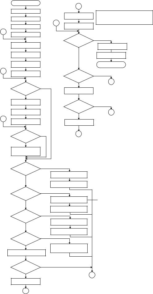
START (Normal mode) |
|
|
|
|
|
L1 |
|
Press the #/P key. |
|
|
In the cause of SIM which is set by touch panel, the |
|
|
|
|
|
|
Press the START key. |
changed content can be stored by the following key, touch. |
|
|
· [OK] key |
|
|
|
|
|
Press the asterisk (*) key. |
|
|
· Other item selection |
|
|
1 |
· ↑ ↓ key |
Press the clear key. |
|
The changed content |
|
|
is stored. |
|
|
|
|
|
|
4 |
|
|
|
Press the asterisk (*) key. |
|
Do you |
|
|
|
YES |
|
|
|
want to end the |
|
Standby for entry of |
|
simulation ? |
|
|
|
Press the clear all key. |
|
SIM code. |
|
NO |
|
|
|
|
|
Enter the main code of |
|
|
The simulation mode |
SIM with the 10-key. |
|
|
is canceled. |
The main code of SIM |
|
|
Returns to START |
is displayed. |
|
|
(Normal mode). |
3 |
|
Do you want |
|
Press the START key. |
|
NO |
|
|
|
to perform another |
|
|
|
simulation ? |
|
|
|
|
2 |
|
|
YES |
|
Is there a sub code ? |
NO |
Press the SYSTEM |
|
|
|
||
|
|
SETTINGS key |
|
YES |
|
|
|
Standby for entry of |
|
|
|
SIM sub code. |
|
Is it the same |
YES |
|
|
||
|
|
simulation ? |
|
Enter the sub code of |
|
|
3 |
SIM with the 10-key. |
|
|
|
|
NO |
|
|
|
|
|
|
2 |
|
Press the SYSTEM |
|
Press the START key. |
|
|
|
|
|
SETTINGS key |
|
Is there a item |
NO |
4 |
|
|
|
||
selection? |
|
|
|
YES |
|
|
|
Select the mode and the |
|
|
|
item with the ↑ ↓ key |
|
|
|
and the item key. |
|
|
|
Operation check ? |
YES |
|
|
|
|
|
|
NO |
|
Press the START key. |
|
|
|
|
|
|
|
Operation is made according |
|
|
|
to the selected mode and item. |
|
Operating conditions |
YES |
|
|
|
|
|
|
check ? |
|
|
If "Operation condition check" |
|
|
Press the START key. |
|
NO |
|
refer to "Sensor display", this |
|
|
|
process is not necessary. |
|
|
|
|
|
|
|
Operation is made according |
|
|
|
to the selected mode and item. |
|
Data clear ? |
YES |
|
|
|
|
|
|
|
|
Press the START key. |
|
NO |
|
Select "YES". |
|
|
|
|
|
|
|
The selected mode and |
|
|
|
the item are cleared. |
|
Adjustments |
NO |
|
|
or setting (counter data |
|
|
|
|
|
|
|
change) ? |
|
|
|
YES |
|
Operation is made according |
|
|
to the select ed mode and the it |
|
|
|
|
|
|
The display is made according |
(Other modes) |
|
|
to the selected mode and the item. |
|
|
|
Do you |
NO |
|
|
want to change the |
|
|
|
|
|
|
|
content ? |
|
|
|
YES |
|
|
1 |
Enter the new setting and |
|
|
|
adjustment values. |
|
|
|
L1 |
|
|
|
AR-5726/5731 SIMULATION 6 - 2
 Loading...