


LC-13S1U LC-15S1U LC-20S1U
LIQUID CRYSTAL TELEVISION TÉLÉVISEUR ACL TELEVISOR CON PANTALLA
DE CRISTAL LÍQUIDO
TELEVISOR DE CRISTAL LÍQUIDO
OPERATION MANUAL MODE D’EMPLOI MANUAL DE OPERACIÓN MANUAL DE OPERAÇÃO
ENGLISH
FRANÇAIS
 PORTUGUÊS ESPAÑOL
Products that have earned the ENERGY STARb are designed to protect the environment through superior energy efficiency.
LC-13S1U
LC-15S1U
LC-20S1U
LIQUID CRYSTAL TELEVISION
ENGLISH
OPERATION MANUAL
IMPORTANT:
To aid reporting in case of loss or theft, please record the TV’s model and serial numbers in the space provided. The numbers are located at the rear of the TV.
Model No.:
Serial No.:
U.S.A. ONLY
IMPORTANT INFORMATION
WARNING: TO REDUCE THE RISK OF FIRE OR ELECTRIC SHOCK, DO
NOT EXPOSE THIS PRODUCT TO RAIN OR MOISTURE.
CAUTION |
RISK OF ELECTRIC SHOCK |
DO NOT OPEN |
CAUTION: TO REDUCE THE RISK OF ELECTRIC SHOCK, |
DO NOT REMOVE COVER (OR BACK). |
NO USER-SERVICEABLE PARTS INSIDE. |
REFER SERVICING TO QUALIFIED SERVICE |
PERSONNEL. |
The lightning flash with arrowhead symbol, within an equilateral triangle, is intended to alert the user to the presence of uninsulated “dangerous voltage” within the product’s enclosure that may be of sufficient magnitude to constitute a risk of electric shock to persons.
The exclamation point within a triangle is intended to alert the user to the presence of important operating and maintenance (servicing) instructions in the literature accompanying the product.
ENGLISH

IMPORTANT INFORMATION (Continued)
WARNING: FCC Regulations state that any unauthorized changes or modifications to this equipment not expressly approved by the manufacturer could void the user’s authority to operate this equipment.
U.S.A. ONLY
CAUTION: TO PREVENT ELECTRIC SHOCK, MATCH WIDE BLADE OF
PLUG TO WIDE SLOT, FULLY INSERT.
“Note to CATV system installer: This reminder is provided to call the CATV system installer’s attention to Article 820-40 of the National Electrical Code that provides guidelines for proper grounding and, in particular, specifies that the cable ground shall be connected to the grounding system of the building, as close to the point of cable entry as practical.”
This product utilizes tin-lead solder, and fluorescent lamp containing a small amount of mercury. Disposal of these materials may be regulated due to environmental considerations. For disposal or recycling information, please contact your local authorities or the Electronic Industries Alliance: www.eia.org
2

DEAR SHARP CUSTOMER
Thank you for your purchase of the Sharp Liquid Crystal Television. To ensure safety and many years of trouble-free operation of your product, please read the Important Safety Precautions carefully before using this product.
IMPORTANT SAFETY PRECAUTIONS
Electricity is used to perform many useful functions, but it can also cause personal injuries and property damage if improperly handled. This product has been engineered and manufactured with the highest priority on safety. However, improper use can result in electric shock and/or fire. In order to prevent potential danger, please observe the following instructions when installing, operating and cleaning the product. To ensure your safety and prolong the service life of your Liquid Crystal Television, please read the following precautions carefully before using the product.
■Read instructions—All operating instructions must be read and understood before the product is operated.
■Keep this manual in a safe place—These safety and operating instructions must be kept in a safe place for future reference.
■Observe warnings—All warnings on the product and in the instructions must be observed closely.
■Follow instructions—All operating instructions must be followed.
■Attachments—Do not use attachments not recommended by the manufacturer. Use of inadequate attachments can result in accidents.
■Power source—This product must operate on a power source specified on the specification label. If you are not sure of the type of power supply used in your home, consult your dealer or local power company. For units designed to operate on batteries or another power source, refer to the operating instructions.
■Power cord protection—The power cords must be routed properly to prevent people from stepping on them or objects from resting on them. Check the cords at the plugs and product.
■If the AC adapter is misplaced or needs to be replaced, obtain the same type of adapter from a SHARP service center or your dealer.
■Overloading—Do not overload AC outlets or extension cords. Overloading can cause fire or electric shock.
■Entering of objects and liquids—Never insert an object into the product through vents or openings. High voltage flows in the product, and inserting an object can cause electric shock and/or short internal parts. For the same reason, do not spill water or liquid on the product.
■Servicing—Do not attempt to service the product yourself. Removing covers can expose you to high voltage and other dangerous conditions. Request a qualified service person to perform servicing.
■Repair—If any of the following conditions occurs, unplug the power cord from the AC outlet, and request a qualified service person to perform repairs.
a.When the power cord or plug is damaged.
b.When a liquid was spilled on the product or when objects have fallen into the product.
c.When the product has been exposed to rain or water.
d.When the product does not operate properly as described in the operating instructions.
Do not touch the controls other than those described in the operating instructions. Improper adjustment of controls not described in the instructions can cause damage, which often requires extensive adjustment work by a qualified technician.
e.When the product has been dropped or damaged.
f.When the product displays an abnormal condition. Any noticeable abnormality in the product indicates that the product needs servicing.
■Replacement parts—In case the product needs replacement parts, make sure that the service person uses replacement parts specified by the manufacturer, or those with the same characteristics and performance as the original parts. Use of unauthorized parts can result in fire, electric shock and/or other danger.
■Safety checks—Upon completion of service or repair work, request the service technician to perform safety checks to ensure that the product is in proper operating condition.
■Wall or ceiling mounting—When mounting the product on a wall or ceiling, be sure to install the product according to the method recommended by the manufacturer.
■Polarization—This AC adapter may be equipped with a polarized alternating current line plug (a plug having one blade wider than the other). This plug will fit into the power outlet only one way. This is a safety feature. If you are unable to insert the plug fully into the outlet, try reversing the plug. If the plug should still fail to fit, contact your electrician to replace your obsolete outlet.
Do not defeat the safety purpose of the polarized plug.
3

IMPORTANT SAFETY PRECAUTIONS (Continued)
■ Cleaning—Unplug the power cord from the AC outlet before cleaning the product. Use a damp cloth to clean the product. Do not use liquid cleaners or aerosol cleaners.
■ Water and moisture—Do not use the product near water, such as bathtub, washbasin, kitchen sink and laundry tub, swimming pool and in a wet basement.
■Stand—Do not place the product on an unstable cart, stand, tripod or table. Placing the product on an unstable base can
cause the product to fall, resulting in serious personal injuries as well as damage to the product. Use only a cart, stand, tripod, bracket or table recommended by the manufacturer or sold with the product. When mounting the product on a wall, be sure to follow the manufacturer’s instructions. Use only the mounting hardware recommended by the manufacturer.
■When relocating the product placed on a cart, it must be moved with utmost care. Sudden stops, excessive force and uneven floor surface can cause the product to fall from the
cart.
■ Ventilation—The vents and other openings in the cabinet are designed for ventilation. Do not cover or block these vents and openings since insufficient ventilation can cause overheating and/or shorten the life of the product. Do not place the product on a bed, sofa, rug or other similar surface, since they can block ventilation openings. This product is not designed for built-in installation; do not place the product in an enclosed place such as a bookcase or rack, unless proper ventilation is provided or the manufacturer’s instructions are followed.
■ The Liquid Crystal panel used in this product is made of glass. Therefore, it can break when the product is dropped or applied with impact. Be careful not to be injured by broken glass pieces in case the Liquid Crystal panel breaks.
■Heat sources—Keep the product away from heat sources such as radiators, heaters, stoves and other heat-generating products (including amplifiers).
■The Liquid Crystal panel is a very high technology product with 921,600 thin film transistors, giving you fine picture details.
Occasionally, a few non-active pixels may appear on the screen as a fixed point of blue, green or red. Please note that this does not affect the performance of your product.
4
IMPORTANT SAFETY PRECAUTIONS (Continued)
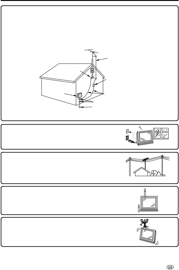
■Outdoor Antenna Grounding – If an outside antenna is connected to the television equipment, be sure the antenna system is grounded so as to provide some protection against voltage surges and built-up static charges. Article 810 of the National Electrical Code, ANSI/NFPA 70, provides information with regard to proper grounding of the mast and supporting structure, grounding of the lead-in wire to an antenna discharge unit, size of grounding conductors, location of antenna discharge unit, connection to grounding electrodes, and requirements for the grounding electrode.
EXAMPLE OF ANTENNA GROUNDING AS PER
NATIONAL ELECTRICAL CODE, ANSI/NFPA 70
|
ANTENNA |
|
LEAD IN |
|
WIRE |
GROUND |
|
CLAMP |
|
|
ANTENNA |
ELECTRIC |
DISCHARGE UNIT |
(NEC SECTION 810-20) |
|
SERVICE |
|
EQUIPMENT |
GROUNDING CONDUCTORS |
|
|
|
(NEC SECTION 810-21) |
|
GROUND CLAMPS |
|
POWER SERVICE GROUNDING |
|
ELECTRODE SYSTEM |
NEC—NATIONAL ELECTRICAL CODE |
(NEC ART 250, PART H) |
■ Lightning – For added protection for this television equipment during a lightning storm, or when it is left unattended and unused for long period of time, unplug it from the wall outlet and disconnect the antenna. This will prevent damage to the equipment due to lightning and power-line surges.
■ Power Lines – An outside antenna system should not be located in the vicinity of overhead power lines or other electric light or power circuits, or where it can fall into such power lines or circuits. When installing an outside antenna system, extreme care should be taken to keep from touching such power lines or circuits as contact with them might be fatal.
■ To prevent fire, never place any type of candle or naked flames on the top or near the TV set.
■ To prevent fire or shock hazard, do not expose this product to dripping or splashing. No objects filled with liquids, such as vases, should be placed on the product.
5

CONTENTS |
|
|
Page |
IMPORTANT INFORMATION ....................................................................................................... |
1, 2 |
DEAR SHARP CUSTOMER ............................................................................................................. |
3 |
IMPORTANT SAFETY PRECAUTIONS ....................................................................................... |
3-5 |
CONTENTS ....................................................................................................................................... |
6 |
SUPPLIED ACCESSORIES ............................................................................................................. |
7 |
PREPARATION ............................................................................................................................ |
8-11 |
Using the Remote Control ......................................................................................................... |
8 |
Batteries for the Remote Control .............................................................................................. |
8 |
Removing the Terminal Cover .................................................................................................. |
9 |
Bundling Cables with Clamp ..................................................................................................... |
9 |
Antenna Connection ........................................................................................................... |
10, 11 |
Power Connection .................................................................................................................... |
11 |
DISPLAY AND CONTROL OVERVIEW .................................................................................. |
12, 13 |
REMOTE CONTROL ...................................................................................................................... |
14 |
EZ SETUP (WITH AUTO CLOCK SETTING) .......................................................................... |
15, 16 |
EZ SETUP during the First Power On .............................................................................. |
15, 16 |
SETTING THE CLOCK ............................................................................................................. |
17-19 |
AUTO CLOCK Setting ......................................................................................................... |
17, 18 |
MANUAL CLOCK Setting ......................................................................................................... |
19 |
BASIC OPERATION ................................................................................................................. |
20-24 |
TV signals in your region ........................................................................................................ |
20 |
Turning on POWER ................................................................................................................... |
21 |
Standby ...................................................................................................................................... |
21 |
Switching TV/VIDEO [AV1/AV2/COMPONENT/TV] Modes ................................................... |
22 |
Sound Volume ........................................................................................................................... |
23 |
Listening with Headphones ..................................................................................................... |
23 |
Changing Channels .................................................................................................................. |
24 |
SELECTING MENU ITEMS ............................................................................................................ |
25 |
Selecting Menu Items .............................................................................................................. |
25 |
ADJUSTMENTS ........................................................................................................................ |
26-46 |
Adjusting SLEEP TIMER Settings ........................................................................................... |
26 |
Adjusting BRIGHTNESS Settings ........................................................................................... |
27 |
Adjusting PICTURE FLIP Settings .......................................................................................... |
28 |
Adjusting AUDIO ONLY Settings ............................................................................................ |
29 |
Adjusting PRESET Settings .................................................................................................... |
30 |
Adjusting LANGUAGE Settings .............................................................................................. |
31 |
Adjusting VIDEO ADJUST Settings .................................................................................. |
32, 33 |
Adjusting AUDIO ADJUST Settings ........................................................................................ |
34 |
SET UP ................................................................................................................................. |
35, 36 |
Adjusting BLUE SCREEN Settings ......................................................................................... |
37 |
Adjusting CLOSED CAPTION Settings ............................................................................ |
38, 39 |
Adjusting V-CHIP Settings .................................................................................................. |
40-46 |
CONNECTING EXTERNAL DEVICES ..................................................................................... |
47-49 |
TROUBLESHOOTING .............................................................................................................. |
50, 51 |
SPECIFICATIONS ........................................................................................................................... |
52 |
DIMENSIONAL DRAWINGS ..................................................................................................... |
53-55 |
CALLING FOR SERVICE ............................................................................................................... |
56 |
LIMITED WARRANTY .............................................................................................................. |
56, 57 |
6
SUPPLIED ACCESSORIES
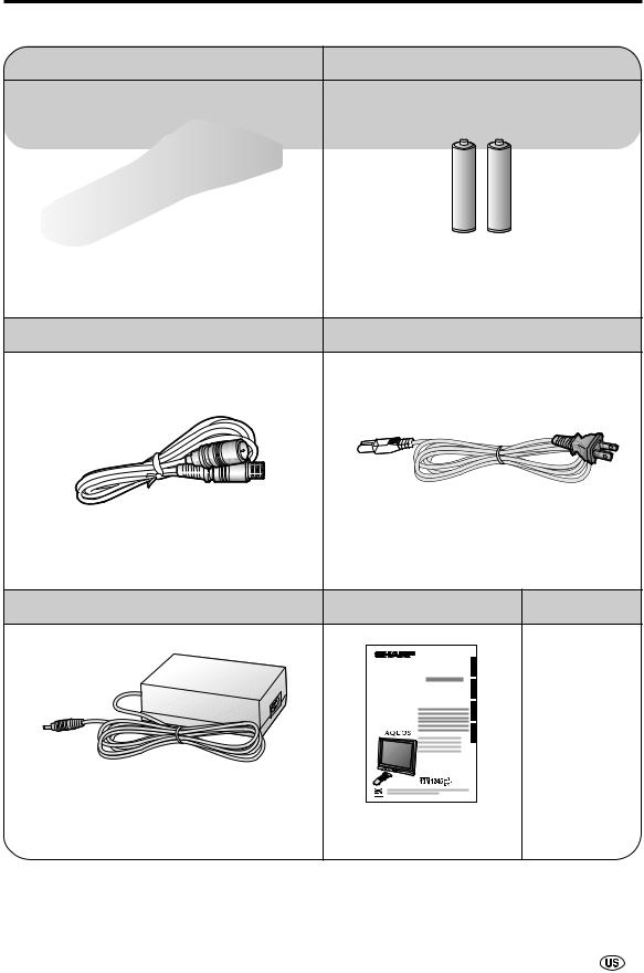
Make sure the following accessories are provided with the product.
Remote Control |
“AAA” size Battery (×2) |
|
|
|
|
RRMCGA174WJSA
Antenna Cable |
AC Cord |
QCNWG0003CEPA |
QACCDA023WJPA |
|
AC Adapter |
Operation Manual |
Cable Clamp |
|
ENGLISH |
|
|
FRANÇAIS |
|
|
ESPAÑOL |
|
|
PORTUGUÊS |
|
UADP-0212CEZZ |
UBATU0026GEZZ |
|
UADP-A044WJPZ |
TINS-A857WJZZ |
LHLDWA002WJSB |
A
•AC cord enclosed in this product is an object for 110-125V. In using it on the 125-240V AC, please consult to the following.
SHARP ELECTRONICS CORPORATION
1300 Naperville Drive, Romeoville, Illinois 60446-1091, U.S.A. TEL: 630-226-2400
7
PREPARATION
Using the Remote Control
■Use the remote control by pointing it towards the remote control sensor window on the main unit. Objects between the remote control and sensor window may prevent proper operation.
Cautions regarding use of the remote control
■ Do not expose the remote control to shock.  In addition, do not expose the remote control to liquid, and
do not place in an area with high humidity.
■Do not install or place the remote control under direct sunlight. The heat may cause deformation of the unit.
■The remote control may not work properly if the remote control sensor window of the main unit is under direct sunlight or strong lighting. In such case, change the angle of the lighting or LCD TV set, or operate the remote control closer to the remote control sensor window.
POWER OPC HEADPHONE
HEADPHONE jack
OPC indicator
POWER indicator
Remote control sensor
OPC sensor
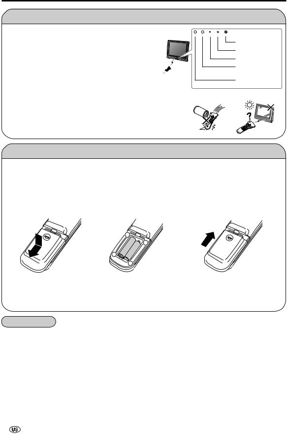
Batteries for the Remote Control
Before using the LCD TV set for the first time, install two (“AAA” size) batteries (supplied). When the batteries become depleted and the remote control fails to operate, replace the batteries with new (“AAA” size) batteries.
1 Open the battery |
2 Insert two (“AAA” size) |
3 Close the battery |
cover. |
batteries. |
cover. |
|
– |
|
|
+ |
|
|
+ |
|
|
– |
|
■Slide the cover while pressing the (Y) part.
■Position the positive and negative ends of the batteries as indicated in the compartment.
■Engage the claw on the cover into the battery housing and slide shut.
 Caution!
Cautions regarding batteries
Improper use of batteries can result in chemical leakage and/or explosion. Be sure to follow the instructions below.
•Place batteries with their terminals corresponding to the (+) and (–) as indicated in the compartment.
•Different types of batteries have different characteristics. Do not mix batteries of different types.
•Do not mix old and new batteries. Mixing old and new batteries can shorten the life of new battery and/or cause the old battery to leak chemicals.
•Remove batteries when they become weak.
Chemicals that leak from batteries can cause a rash. If chemical leakage is found, wipe with a cloth.
•The batteries supplied with the product may have a shorter life expectancy due to storage conditions.
•If the remote control will not be used for an extended period of time, remove the batteries from the remote control.
8
PREPARATION (Continued)
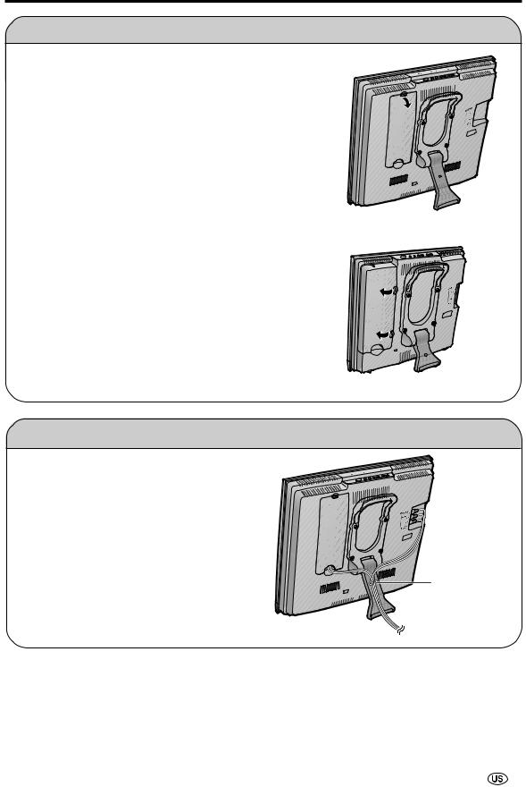
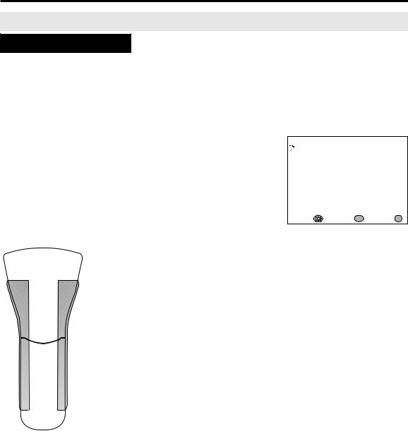
Removing the Terminal Cover
LC-20S1U
■ Before connecting cables and cords to the rear terminals, remove the terminal cover. Push in the tab and pull out the terminal cover carefully.
■ To mount the cover, insert the 2 hooks on the bottom of the cover into the cabinet and press on the upper part of the terminal cover until the tab locks in place with a click.
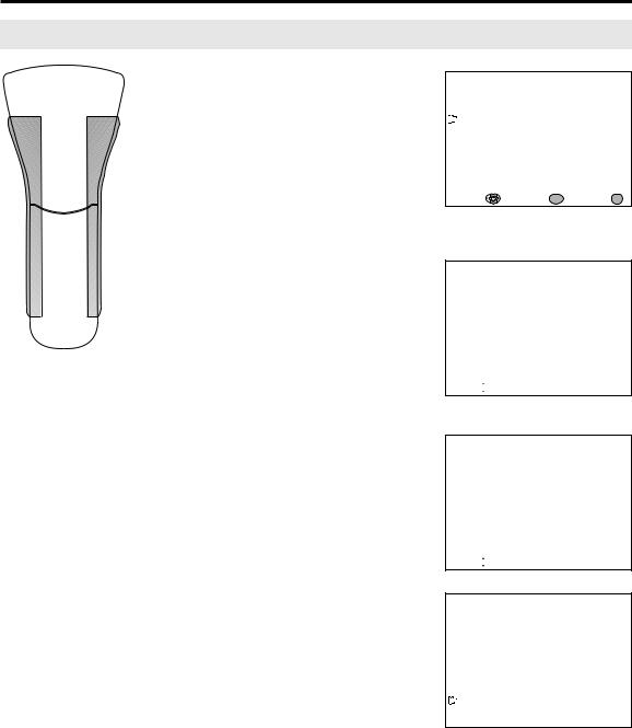
LC-13/15S1U
■ Before connecting cables and cords to the rear terminals, remove the terminal cover. Push in the 2 tabs on the right side of the terminal cover and pull it out carefully to the left.
■ To mount the cover, insert the 2 hooks on the left side of the cover into the cabinet and press on the right part of the cover until the tabs lock into place with a click.
Bundling Cables with Clamp
• Secure cables and cords with the supplied cable clamp so that they do not get caught when mounting the cover.
Cable clamp
9

PREPARATION (Continued)
Antenna Connection
ANTENNAS
•The antenna requirements for good color television reception are more important than those for black & white television reception. For this reason, a good quality outdoor antenna is strongly recommended.
The following is a brief explanation of the type of connections that are provided with the various antenna systems.
F-type connector
1.A 75-ohm system is generally a round cable with F-type connector that can easily be attached to a terminal without tools (not supplied).
2.A 300-ohm system is a flat “twin-lead” cable that can be attached to a 75-ohm terminal through a 300-75-ohm adapter (not supplied).
75-ohm coaxial cable (round)
300-ohm twin-lead cable (flat)
OUTDOOR ANTENNA CONNECTION
•Use one of the following two diagrams if you connect an outdoor antenna.
A:Using a VHF/UHF combination outdoor antenna
B:Using separate VHF and/or UHF outdoor antennas
•Connect the outdoor antenna cable lead-in to ANT. (Antenna terminal) on the rear of the TV set.
ANT.
(Antenna terminal)
A. Combination VHF/UHF Antenna |
|
VHF/UHF |
300/75-ohm |
adapter |
|
antenna |
(not supplied) |
or |
VHF/UHF |
antenna |
|
|
300-ohm |
|
twin-lead |
75-ohm |
|
coaxial cable |
|
Antenna cable (supplied)
B. Separate VHF and/or
UHF Antennas
UHF
VHF antenna antenna
300-ohm twin-lead
Combiner 300-ohm (not supplied) twin-lead 
 IN OUT


or |
75-ohm |
|
coaxial cable |
NOTICE |
F-type connector |
75-ohm coaxial cable
F-type connector should be finger-tightened only.
When connecting the RF cable to the TV set, do not tighten F-type connector with tools.
If tools are used, it may cause damage to your TV set.
(The breaking of internal circuit, etc.)
10 
PREPARATION (Continued)
Antenna Connection (Continued)
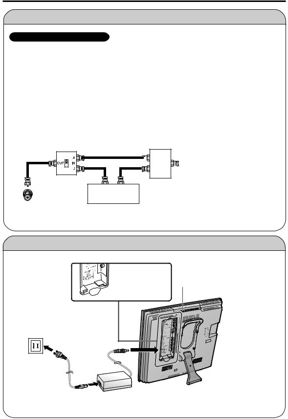
CABLE TV (CATV) CONNECTION
•A 75-ohm coaxial cable connector is built into the set for easy hookup. When connecting the 75ohm coaxial cable to the set, screw the 75-ohm cable to the ANT. terminal.
•Some cable TV companies offer “premium pay channels”. Since the signals of these premium pay channels are scrambled, a cable TV converter/descrambler is generally provided to the subscriber by the cable TV company. This converter/descrambler is necessary for normal viewing of the scrambled channels. (Set your TV to channel 3 or 4, typically one of these channels is used. If this is unknown, consult your cable TV company.) For more specific instructions on installing cable TV, consult your cable TV company. One possible method of utilizing the converter/descrambler provided by your cable TV company is explained below.
Please note: An RF switch provided with two inputs (A and B) is required (not supplied).
“A” position on the RF switch (not supplied):
“B” position on the RF switch (not supplied):
You can view all unscrambled channels by using the TV’s channel keys.
You can view the scrambled channels via the converter/ descrambler by using the converter’s channel keys.
RF switch (not supplied)
Two-set 


 signal
splitter 


 Cable TV Line
(not supplied)
OUT |
IN |
Cable TV converter/ descrambler (not supplied)
A
•Consult your SHARP Dealer or Service Center for the type of splitter, RF switch or combiner that might be required.
Power Connection

 POWER INPUT terminal (DC12V)
MAIN POWER
Household power outlet
AC adapter
AC cord
A
•Use a commercially available AC plug adapter, if necessary, depending on the design of the wall outlet.
•Always turn the MAIN POWER switch of the LCD TV set to off when connecting the AC adapter.
•Unplug the AC adapter from the product and power outlet when not using for a long period of time.
 11
11
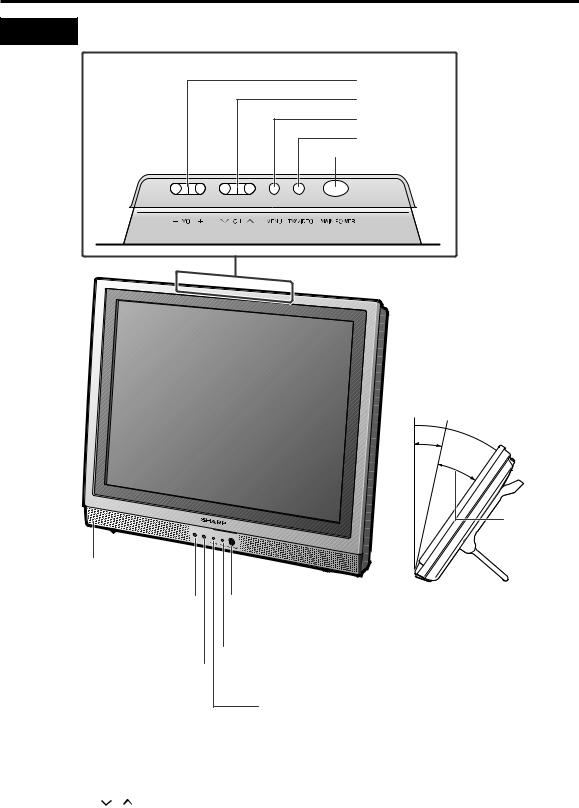
DISPLAY AND CONTROL OVERVIEW
Controls
Upper control panel
VOL (–)/(+)
CH ( )/(
)/( ) MENU
TV/VIDEO
 MAIN POWER
Speaker
OPC sensor 
Remote control sensor 
The screen can be adjusted backwards to an angle between 12 degrees and 35 degrees. The screen cannot be set up straight. When changing the angle, make sure to hold the stand and adjust the screen to the best viewable angle.
 35° 12°
Adjustable range
 HEADPHONE jack
Plug the headphone mini-plug into the HEADPHONE jack located on the front of the TV set.
 OPC indicator (Optical Picture Control)
The Optical Picture Control indicator lights up green when the BRIGHTNESS is set to AUTO. (See page 27.)
12 
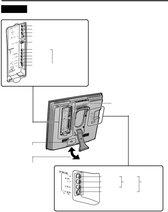
DISPLAY AND CONTROL OVERVIEW (Continued)
Terminals
VIDEO |
|
|
|
AUDIO (L) |
|
|
AV-IN1 |
AUDIO (R) |
|
|
|
|
|
|
|
S-VIDEO |
|
|
|
|
|
|
|
ANT. (Antenna terminal) |
|||
Y
PB
PR |
|
|
COMPONENT |
||
|
|||||
AUDIO (L) |
|
||||
AUDIO (R) |
|
|
|
|
|
|
|
|
|||
POWER INPUT |
|
||||
(DC12V) |
|
||||
Carrying handle
Round lock for Kensington Security Standard Slot.
Stand
●The screen can be adjusted backwards to an angle between 12 and 35 degrees. When changing the
angle, make sure to hold the stand and adjust to the best viewable angle.
*Be careful to prevent the product from falling over when adjusting the angle. Also place the product on a stable base.
AUDIO (R) |
|
AUDIO (L) |
AV-OUT AV-IN2 |
VIDEO
S-VIDEO (INPUT ONLY)
 13
13
REMOTE CONTROL
1
2
3
4
5
6
7
8
9
POWER
|
BRIGHT |
SLEEP |
PIC. FLIP |
|
ENTER |
DISPLAY |
MENU |
AUDIO
MUTE ONLY CC TV/VIDEO
FLASH-
BACK
VOL CH
|
1 |
POWER (p. 21) |
|
|
|
Switch the Liquid Crystal Television power |
|
10 |
|
on or off. |
|
2 |
SLEEP (p. 26) |
||
11 |
|||
|
Set the sleep timer. |
||
|
|
||
12 |
3 |
ENTER |
|
|
|||
13 |
|
Execute a command. |
|
4 |
DISPLAY |
||
14 |
|||
|
Display the channel and time information. |
||
|
|
155 AUDIO ONLY (p. 29)
16Output audio without screen image.
6 |
MUTE (p. 23) |
|
Mute the sound. |
7 |
VOL (+)/(–) (p. 23) |
17 |
Set the volume. |
|
|
8 |
CH ( )/( ) (p. 24) |
|
Select channel. |
9 |
MTS (p. 23) |
|
Select audio settings. |
10 BRIGHT (p. 27)
Adjust the brightness of the screen.
11 PIC. FLIP (p. 28)
Set the orientation of the picture.
12 a/b/c/d(Cursor control) (p. 15)
Select a desired item on the screen.
13 MENU (p. 17)
Display the menu screen.
14 CC (p. 38)
Display Closed Caption subtitles.
15 TV/VIDEO (p. 22)
Select a Liquid Crystal Television input source.
16 FLASHBACK (p. 24)
Return to the previous channel.
17 Channel Select (p. 24)
Set the channel.
14 
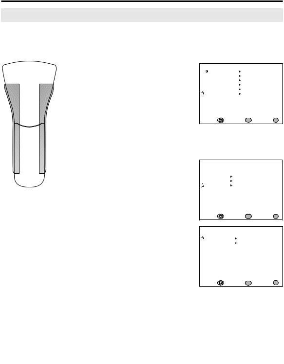
EZ SETUP (WITH AUTO CLOCK SETTING)
EZ SETUP during the First Power On
Control section of main unit ■ When you turn on the TV for the first time, it will automatically memorize the broadcasting channels and clock.
Please perform the following instructions before you press MAIN
MAIN POWER POWER.
(1)Insert the batteries into the remote control. (See page 8.)
(2)Connect the antenna cable to the TV set. (See page 10.)
(3) Connect the AC adapter to the POWER INPUT terminal of the product and plug in the AC cord to the wall outlet. (See page 11.)
POWER
BRIGHT
1
2
3
Press MAIN POWER, located on the upper side of the main unit, to turn on the TV. The SELECT LANGUAGE mode will be displayed.
Press a/bto select “ENGLISH”, “ESPAÑOL (SPANISH)” or “FRANCAIS (FRENCH)”, and press
ENTER.
Press a/b to select ON or OFF. When you select ON, the TV set will automatically memorize the broadcasting channels.
SLEEP |
PIC. FLIP |
|
Press ENTER to access AUTO |
|
|
|
|
|
ENTER |
|
CLOCK mode. |
DISPLAY |
MENU |
|
|
MUTE |
AUDIO |
ENTER/ |
4 Press a/bto select ON or OFF. |
ONLY CC TV/VIDEO |
a/b |
||
|
FLASH- |
|
|
|
BACK |
|
|
VOL |
CH |
|
When you select ON, the TV set |
|
|
|
|
|
|
|
will automatically search the time |
|
|
MENU |
signals (EDS signals), provided by |
|
|
some TV stations, to adjust the |
|
|
|
|
|
|
|
|
clock. The AUTO CLOCK setting |
|
|
|
may take from several minutes to |
|
|
|
an hour depending on the number |
|
|
|
of channels to receive and signal |
|
|
|
status. If you know the channel of |
|
|
|
the EDS signal carrier (PBS or |
|
|
|
other) in your area, select OFF and |
|
|
|
follow the procedure in AUTO |
|
|
|
CLOCK Setting. (See pages 17, |
|
|
|
18) |
5Press ENTER to access EZ SETUP mode.
A
• If you select OFF in “EZ SETUP CH-SETTING”, EZ SETUP will be canceled.
SE LECT LANGUAGE
ENGL I SH
ESPAÑOL
FRANCA I S
SELECT : |
ENTER : ENTER |
EX I T : MENU |
E Z SE TUP
CH - SE T T I NG
ON
OFF
SELECT : |
ENTER : ENTER |
EX I T : MENU |
E Z SE TUP
AUTO CLOCK
ON
OFF
SELECT : |
ENTER : ENTER |
EX I T : MENU |
 15
15
EZ SETUP (WITH AUTO CLOCK SETTING) (Continued)
EZ SETUP during the First Power On (Continued)
POWER
|
BRIGHT |
SLEEP |
PIC. FLIP |
|
ENTER |
DISPLAY |
MENU |
MUTE |
AUDIO |
ENTER/ |
|
ONLY |
CC TV/VIDEO |
a/b/c/d |
|
|
|
FLASH- |
|
|
|
BACK |
|
VOL |
CH |
|
|
 MENU
MENU
6Press a/bto select YES, and press ENTER.
If you want to stop the EZ SETUP
process once it has started, press cand it will be canceled. If you want to SET UP again, please refer to pages 35 and 36 on SET UP.
To cancel EZ SETUP
Press a/bto select NO, and press ENTER.
The tuner will automatically search for the broadcasting and cable TV channels. (The CH No. will automatically increase when it appears.)
CONNECT ANTENNA OR CABLE.
START EZ SETUP?
YES
NO
SELECT : |
ENTER : ENTER |
EX I T : MENU |
PLEASE WA I T
AUTO PROGRAMMI NG
STOP :

The TV set will automatically search for EDS signals.
If EDS signals are received, the channel number and time will be displayed, and then the screen shown in step 7 appears.
7Once EZ SETUP is completed, the lowest channel number memorized will be displayed.
PLEASE WA I T
NOW SEARCH I NG T IME
STOP :

2
STEREO |
<ON A I R |
SAP |
11 : 53AM |
MONO |
A
•Do not let the EZ SETUP screen remain unattended for a long time.
•If EZ SETUP does not memorize all the channels in your region, please refer to pages 35 and 36 for more information on manually memorizing the channels using CHANNEL SETTING.
•It may be difficult to preset when the broadcasting signals are weak, the channel cycle frequency is incorrect or the frequency jamming is occurring around the area. Please refer to pages 35 and 36 for more information on manually memorizing channels using CHANNEL SETTING.
•If there are no channels with EDS signals or the antenna signal is weak, the AUTO CLOCK Setting may not operate. In this case, a “EDS CH IS NOT AVAILABLE” message will display and the mode will change to MANUAL CLOCK Setting. Refer to page 19 to set the clock manually.
16 
SETTING THE CLOCK
AUTO CLOCK Setting
There are two methods of setting the clock: AUTO CLOCK and MANUAL CLOCK. AUTO CLOCK uses EDS signals, which are provided by some TV stations, to automatically adjust the clock. MANUAL CLOCK set the clock manually in areas where no channel carries EDS signals.
ER |
|
1 Press MENU to display the MENU |
POW |
|
screen. |
|
|
|
BRIGHT |
|
|
SLEEP |
PIC. FLIP |
|
ENTER |
|
|
DISPLAY |
MENU |
|
AUDIO |
ENTER/ |
|
MUTE ONLY CC TV/VIDEO a/b |
2 Press a/bto move the cursor to |
|
BACK |
|
|
FLASH- |
|
SET UP, and press ENTER. |
VOL CH |
|
|
|
MENU |
|
MENU
 SLEEP T IMER
 AV ADJUST
 PRESET
 CLOSED CAPT I ON
 V–CH I P BLOCK
 SET UP
SELECT : |
ENTER : ENTER |
EX I T : MENU |
3Press a/bto move the cursor to CLOCK, and press ENTER.
4Press a/bto move the cursor to AUTO CLOCK, and press ENTER.
SET UP
 RETURN
BLUE SCREEN [ OFF ]
LANGUAGE
CH–SETT I NG
CLOCK
SELECT : |
ENTER : ENTER |
EX I T : MENU |
CLOCK
 RETURN
AUTO CLOCK
MANUAL CLOCK
OFF
SELECT : |
ENTER : ENTER |
EX I T : MENU |
A
• The CLOCK can be stopped completely by setting CLOCK to “OFF”.
Time reset for power outage, AC adapter disconnected
If the TV has a power outage or the AC adapter cord is disconnected, the time display will have to be reset. In that case, refer to SETTING THE CLOCK on pages 17 to 19.
 17
17
 Loading...