


EM 100

EM 100
Instruction manual

Contents
1
Contents
Important safety instructions .................................................................................................................. 2
The EM 100 G3 stationary receiver ......................................................................................................... 4
Areas of application ............................................................................................................................... 4
The frequency bank system ................................................................................................................. 5
Delivery includes .......................................................................................................................................... 7
Product overview ......................................................................................................................................... 8
Overview of the EM 100 G3 receiver .................................................................................................. 8
Overview of the displays ...................................................................................................................... 9
Putting the receiver into operation ...................................................................................................... 11
Preparing the receiver for use ........................................................................................................... 11
Connecting an amplifier/mixing console ......................................................................................... 17
Connecting the mains unit ................................................................................................................. 18
Using the receiver ...................................................................................................................................... 19
Switching the receiver on/off ............................................................................................................ 19
Synchronizing a transmitter with the receiver .............................................................................. 20
Deactivating the lock mode temporarily ......................................................................................... 22
Muting the audio signal ...................................................................................................................... 23
Selecting a standard display .............................................................................................................. 24
Using the operating menu ...................................................................................................................... 25
The buttons ........................................................................................................................................... 25
Overview of the operating menu ...................................................................................................... 26
Working with the operating menu ................................................................................................... 28
Adjustment tips and functions .............................................................................................................. 30
Standard displays with additional functions ................................................................................. 30
The main menu “Menu” ...................................................................................................................... 33
The extended menu “Advanced Menu” .......................................................................................... 38
Synchronizing transmitters with receivers ......................................................................................... 42
Synchronizing a transmitter with the receiver – individual operation ..................................... 42
Synchronizing transmitters with receivers – multi-channel operation .................................... 43
Cleaning the receiver ................................................................................................................................ 45
Recommendations and tips .................................................................................................................... 46
If a problem occurs ... ................................................................................................................................ 47
Accessories and spare parts .................................................................................................................... 49
Specifications ............................................................................................................................................. 51
Manufacturer Declarations ..................................................................................................................... 54
Index ............................................................................................................................................................. 56
An animated instruction manual can be viewed on the EM 100 G3 product page on
our website at www.sennheiser.com.

Important safety instructions
2
Important safety instructions
• Read this instruction manual.
• Keep this instruction manual. Always include this instruction manual
when passing the product on to third parties.
• Heed all warnings and follow all instructions in this instruction manual.
• Only clean the product when it is not connected to the mains. Use
a cloth for cleaning.
• Refer all servicing to qualified service personnel.
Servicing is required if the product has been damaged in any way,
liquid has been spilled, objects have fallen inside, the product has been
exposed to rain or moisture, does not operate properly or has been
dropped.
• WARNING: To reduce the risk of short circuits, do not use the product
near water and do not expose it to rain or moisture. Do not place
objects filled with liquids, such as vases or coffee cups, on the product.
• Only use the supplied mains unit.
• Unplug the mains unit from the wall socket
– to completely disconnect the product from the mains,
– during lightning storms or
– when unused for long periods of time.
• Only operate the mains unit from the type of power source specified in
the chapter “Specifications” (see page 51).
• Ensure that the mains unit is
– in a safe operating condition and easily accessible,
– properly plugged into the wall socket,
– only operated within the permissible temperature range,
– not covered or exposed to direct sunlight for longer periods of time
in order to prevent heat accumulation (see “Specifications” on
page 51).
• Do not block any ventilation openings. Install the product in accordance
with the instructions given in this instruction manual.
• Do not install the product near any heat sources such as radiators,
stoves, or other devices (including amplifiers) that produce heat.
• Only use attachments/accessories specified by Sennheiser.

Important safety instructions
3
Overloading
Do not overload wall outlets and extension cables as this may result in fire
and electric shock.
Replacement parts
When replacement parts are required, be sure the service technician uses
replacement parts specified by Sennheiser or those having the same char-
acteristics as the original part. Unauthorized substitutions may result in
fire, electric shock, or other hazards.
Danger due to high volumes
This product is capable of producing sound pressure exceeding 85 dB(A).
85 dB(A) is the sound pressure corresponding to the maximum permis-
sible volume which is by law (in some countries) allowed to affect your
hearing for the duration of a working day. It is used as a basis according to
the specifications of industrial medicine. Higher volumes or longer dura-
tions can damage your hearing. At higher volumes, the duration must be
shortened in order to prevent hearing damage. The following are sure
signs that you have been subjected to excessive noise for too long a time:
• You can hear ringing or whistling sounds in your ears.
• You have the impression (even for a short time only) that you can no
longer hear high notes.
Intended use
Intended use of the ew 100 G3 series products includes:
• having read these instructions especially the chapter “Important
safety instructions”,
• using the products within the operating conditions and limitations
described in this instruction manual.
“Improper use” means using the products other than as described in this
instruction manual, or under operating conditions which differ from those
described herein.
The EM 100 G3 stationary receiver
4
The EM 100 G3 stationary receiver
This receiver is part of the evolution wireless series generation 3 (ew G3).
With this series, Sennheiser offers high-quality state-of-the-art RF trans-
mission systems with a high level of operational reliability and ease of use.
Transmitters and receivers permit wireless transmission with studio-
quality sound.
Features of the evolution wireless 100 G3 series:
• Optimized PLL synthesizer and microprocessor technology
• HDX noise reduction system
• Pilot tone squelch control
• True diversity technology
• Switching bandwidth of 42 MHz
• Scan function (Easy Setup) for scanning the frequency banks for
unused channels
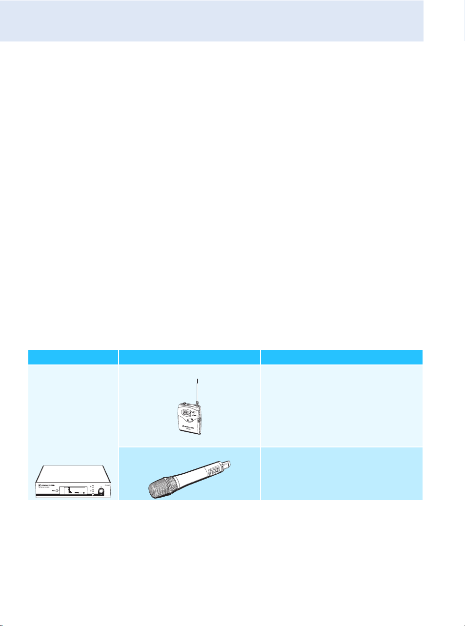
Areas of application
The receiver can be combined with the following optional components of
the ew G3 series (see “Accessories and spare parts” on page 49):
Receiver Transmitters Combinable with
EM 100 G3 SK 100 G3 • Clip-on microphones:
ME 2, ME 4
•Headmic:
ME 3
• Instrument cable:
CI 1
SKM 100 G3 Interchangeable microphone heads:
• MMD 835-1, MMD 845-1
• MME 865-1
533.875
ew100 G3
20.12
MUTE
MHz
SET
P
PEAK
-10
040
30
20
10
-20
-40
AF
RF
-30
The EM 100 G3 stationary receiver
5
The devices are available in the same UHF frequency ranges and are
equipped with the same frequency bank system with factory-preset
frequencies. An advantage of the factory-preset frequencies is that
• a transmission system is ready for immediate use after switch-on,
• several transmission systems can be operated simultaneously on the
preset frequencies without causing intermodulation interference.
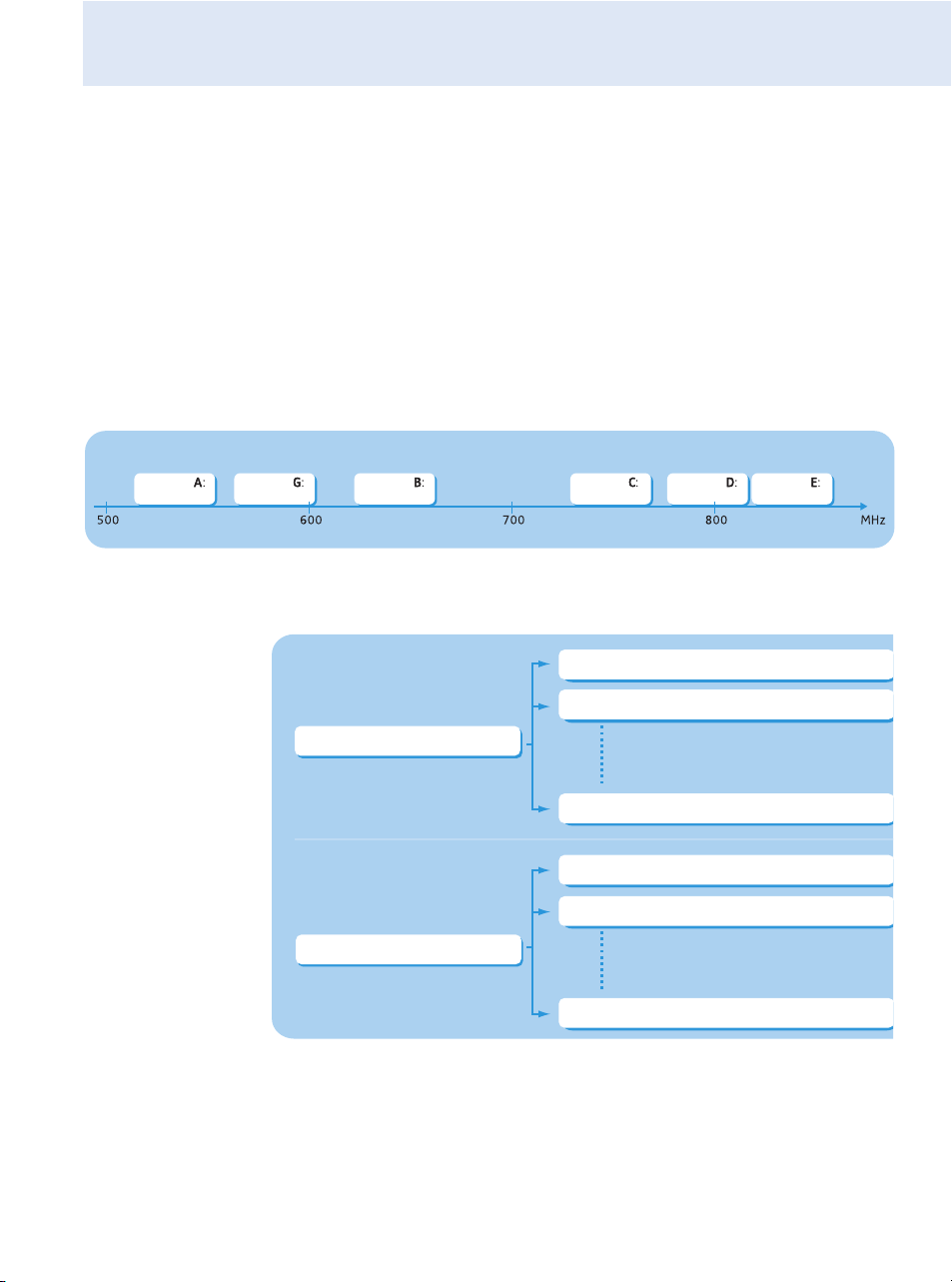
The frequency bank system
The receiver is available in 6 UHF frequency ranges with 1,680 frequencies
per frequency range:
Each frequency range (A–E, G) offers 21 frequency banks with up to
12 channels each:
Range Range Range Range Range Range
516 – 558 566 – 608 626 – 668 734 – 776 780 – 822 823 – 865
Frequency bank 1... 20
Frequency bank U
Channel 12 – frequency preset
Channel 1 – frequency preset
Channel 2 – frequency preset
Channel 12 – freely selectable frequency
Channel 1 – freely selectable frequency
Channel 2 – freely selectable frequency

The EM 100 G3 stationary receiver
6
Each of the channels in the frequency banks “1” to “20” has been factory-
preset to a fixed frequency (frequency preset).
The factory-preset frequencies within one frequency bank are intermodu-
lation-free. These frequencies cannot be changed.
For an overview of the frequency presets, please refer to the supplied
frequency information sheet. Updated versions of the frequency informa-
tion sheet can be downloaded from the EM 100 G3 product page on our
website at www.sennheiser.com.
The frequency bank “U” allows you to freely select and store frequencies.
It might be that these frequencies are not intermodulation-free (see
page 44).

Delivery includes
7
Delivery includes
The packaging contains the following items:
1 EM 100 G3 stationary receiver
1 NT 2-3 or NT 2-1 mains unit with one country adapter
2rod antennas
2 stacking elements
1 instruction manual
1 frequency information sheet
4 device feet
Product overview
8
Product overview
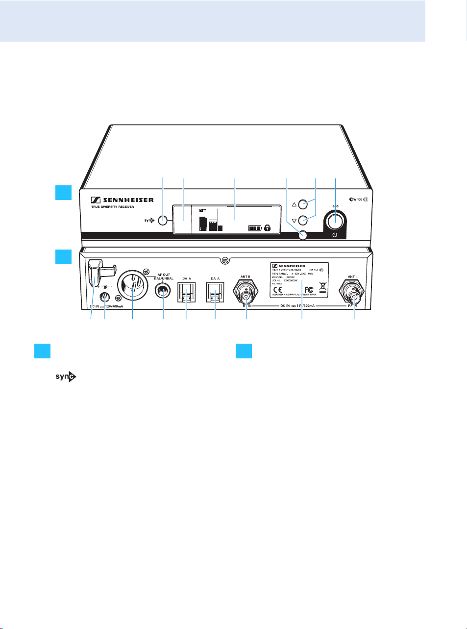
Overview of the EM 100 G3 receiver
Operating elements – front panel Operating elements – rear panel
button
Infra-red interface
Display panel, backlit in orange
SET button
UP/DOWN button
STANDBY button;
ESC function (cancel)
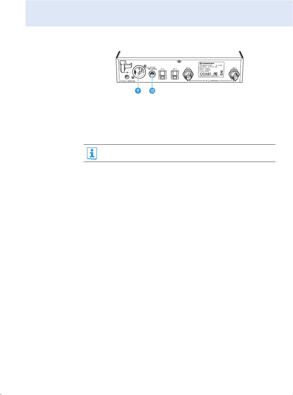
Cable grip for power supply DC cable
DC socket (DC IN) for connection of
NT 2 mains unit
Audio output (AF OUT BAL),
XLR-3M socket, balanced
Audio output (AF OUT UNBAL),
¼” (6.3 mm) jack socket, unbalanced
Service interface (DATA)
Service interface (DATA)
Antenna input II (ANT II) with remote
power supply input, BNC socket
Type plate
Antenna input I (ANT I) with remote
power supply input, BNC socket
533.875
ew100 G3
20.12
MHz
XXXXXXX
0682
쐋
P
SET
PEAK
-10
0
40
25
10
-20
-30
AF
RF
A
B
A
B
Product overview
9
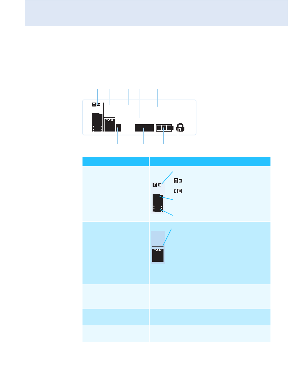
Overview of the displays
After switch-on, the receiver displays the standard display “Receiver
Parameters”. For further illustrations and examples of the different stan-
dard displays, please refer to page 24. This standard display displays the
operating states of the receiver.
Display Meaning
RF level “RF”
(Radio Frequency)
Audio level “AF”
(Audio Frequency,
see page 36)
Frequency bank
and channel
(see page 35)
Current frequency bank and channel number
Frequency
(see page 35)
Current receiving frequency
Name
(see page 36)
Freely selectable name of the receiver
533.875
ew100 G3
20.12
MUTE
MHz
P
PEAK
-10
0
40
25
10
-20
-30
AF
RF
햴
40
25
10
RF
Diversity display:
Antenna input I is active
Antenna input II is active
RF signal level:
Field strength of the received signal
Squelch threshold level
PEAK
-10
0
-20
-30
AF
Modulation of the transmitter
with peak hold function
When the display for audio level
shows full deflection, the audio level
is excessively high. When the trans-
mitter is overmodulated frequently
or for extended periods of time, the
“PEAK” display is shown inverted.
Product overview
10
Pilot tone “P”
(see page 40)
Activated pilot tone evaluation
Muting function
“MUTE”
(see page 23)
Audio signal is muted
(see also page 47)
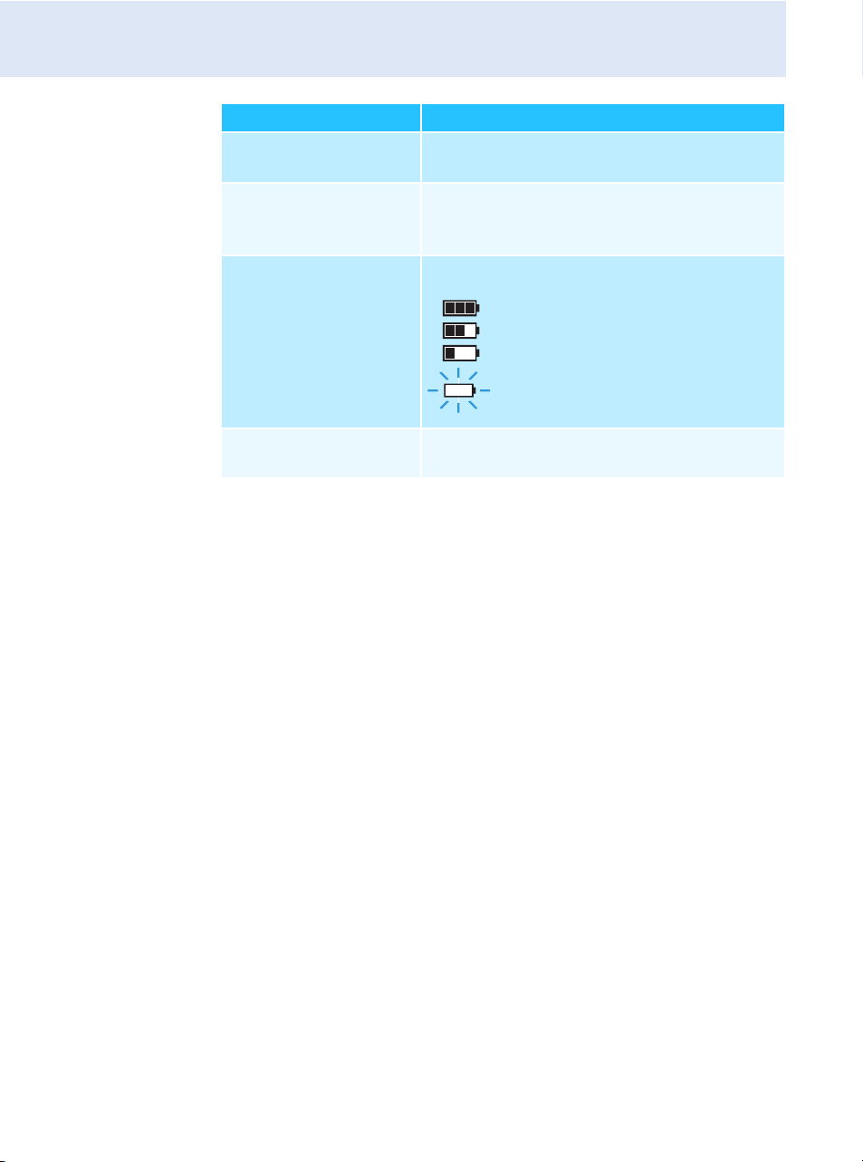
Battery status of
the transmitter
Charge status:
Lock mode icon
(see page 37)
Lock mode is activated
Display Meaning
approx. 100%
approx. 70%
approx. 30%
icon is flashing;
charge status is critical

Putting the receiver into operation
11
Putting the receiver into operation
Preparing the receiver for use
If you want to mount the receiver into a 19” rack:
왘 Read the corresponding chapter on page 13.
If you want to set up the receiver on a flat surface:
왘 Read the next chapter.
Setting up the receiver on a flat surface
Fastening the
stacking elements
Recommendations for optimum reception
To ensure optimum reception even under difficult conditions, we
recommend connecting remote antennas and, if necessary, using
antenna splitters (see “Accessories and spare parts” on page 49).
When rack-mounting the receiver, you can mount the supplied
antennas to the front of the rack by using an antenna front mount
kit. When mounting more than one receiver into a rack, you should
use remote antennas.
CAUTION! Risk of staining of furniture surfaces!
Some furniture surfaces have been treated with varnish, polish or
synthetics which might cause stains when they come into contact with
other synthetics. Despite a thorough testing of the synthetics used by us,
we cannot rule out the possibility of staining.
왘 Do not place the receiver on delicate surfaces.
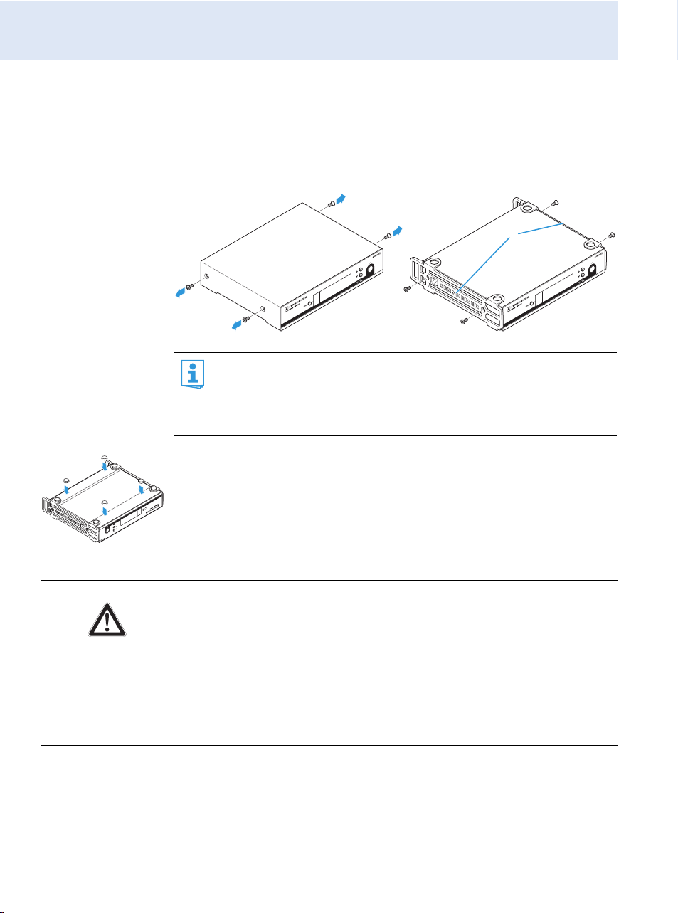
The stacking elements are designed to help protect the operating
elements from damage or deformation, e.g. if the receiver is
dropped. Therefore, fasten the stacking elements, even if you do
not want to stack your receivers.
Putting the receiver into operation
12
To fasten the stacking elements :
왘 Unscrew and remove the two recessed head screws (M4x8) on each
side of the receiver (see left-hand diagram).
왘 Secure the stacking elements to the sides of the receiver using the
previously removed recessed head screws (see right-hand diagram).
Fitting the
device feet
왘 Clean the base of the receiver where you want to fix the device feet.
왘 Fit the device feet to the four corners of the receiver as shown.
왘 Place the receiver on a flat, horizontal surface.
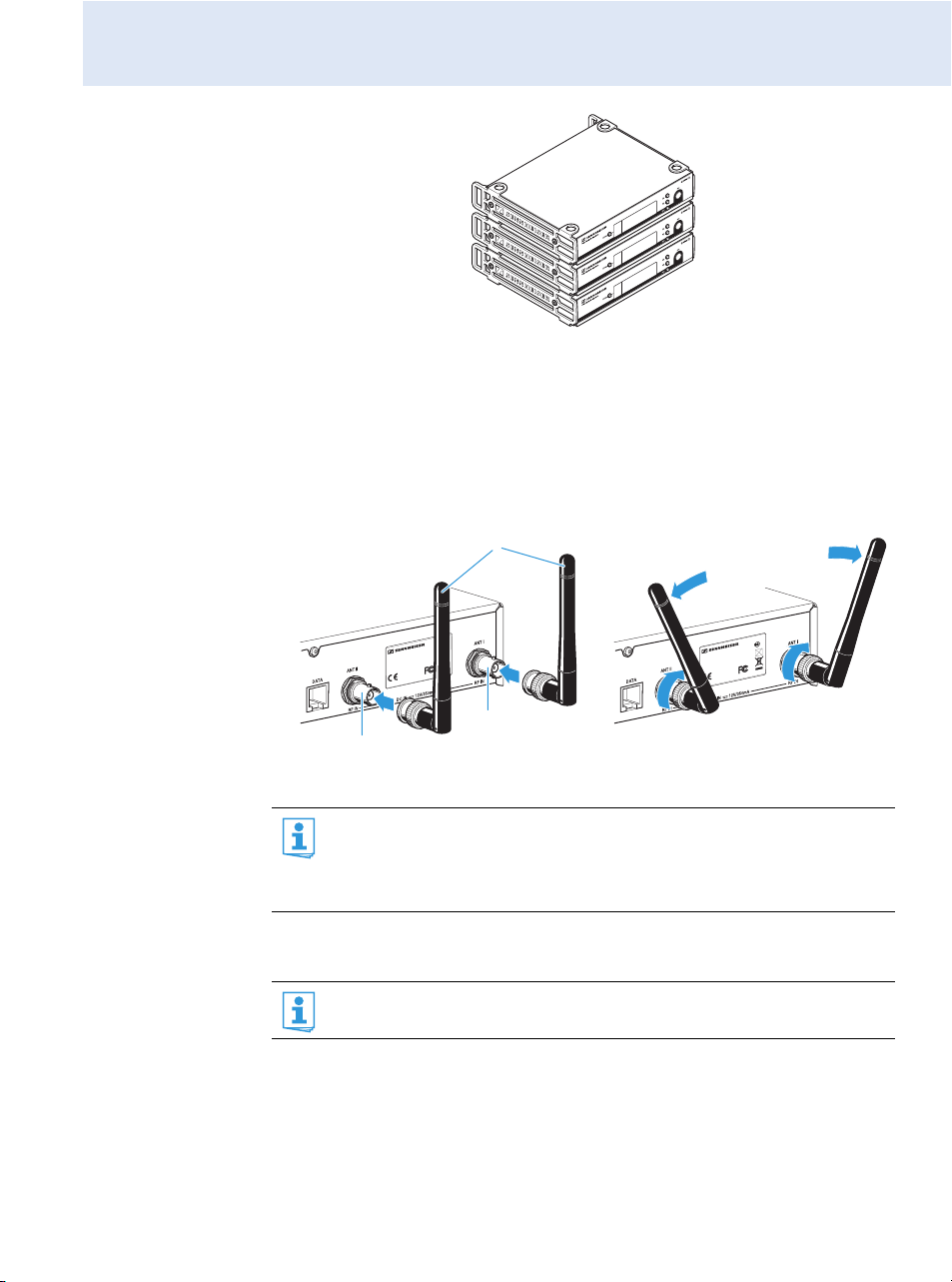
Stacking receivers You can stack several receivers on top of each other.
If you want to stack receivers (see next section), only fit the device
feet to the base of the lowermost receiver.
Do not fit the device feet when mounting the receiver into a
19” rack.
CAUTION! Danger of injury due to toppling receiver stacks!
High receiver stacks can easily topple over.
왘 Place the stack on an absolutely flat surface.
왘 Secure the stack against toppling over.
왘 Fasten the stacking elements as described in the previous section.
왘 Stack the receivers so that the recesses of the stacking elements
completely engage with each other.
Putting the receiver into operation
13
Connecting the
rod antennas
The supplied rod antennas can be mounted quickly and easily and are
suitable for all applications where – good reception conditions provided –
a wireless transmission system is to be used without a large amount of
installation work.
왘 Connect the two rod antennas to the BNC sockets and at the
rear of the receiver.
왘 Align the rod antennas upwards in a V-shape.
Mounting the receiver into a 19” rack
When using more than one receiver, we recommend connecting
remote antennas and, if necessary, using Sennheiser antenna
accessories. Fore more information, visit the ew G3 product page
at www.sennheiser.com.
Do not mount the stacking elements and do not fit the rubber feet
when mounting the receiver into a 19” rack.
XXX - XXX MHzFREQ. RANGE-
X:
SER. NO.: XXXXXXXXXX
TRUE DIVERSITY RECEIVER EM 100
IDENT. NO.: XXXXXX
IC: 2099A- XXX
XXXX
DESIGNED IN GERMANY, ASSEMBLED IN USA
0682
XXX - XXX MHzFREQ. RANGE- X :
SER. NO.: XXXXXXXXXX
TRUE DIVERSITY RECEIVER EM 100
IDENT. NO.: XXXXXX
IC: 2099A- XXXXXXX
DESIGNED IN GERMANY, ASSEMBLED IN USA
0682
Putting the receiver into operation
14
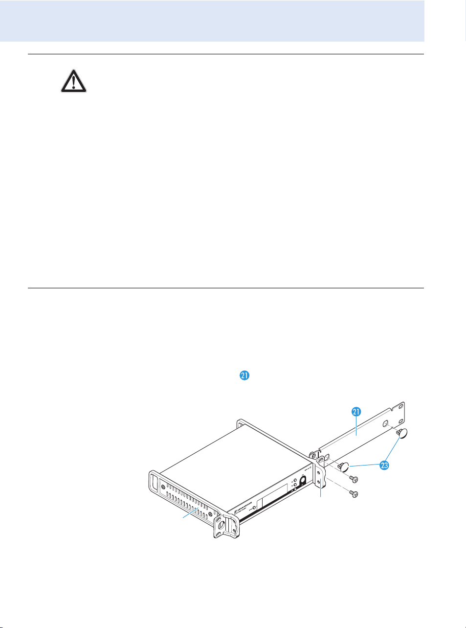
Rack mounting
one receiver
To mount the receiver into a rack, you require the GA 3 rack adapter (see
“Accessories and spare parts” on page 49):
왘 Secure the rack mount “ears” of the GA 3 rack adapter to the
receiver in the same way as described for the stacking elements (see
page 11).
왘 Secure the blanking plate of the GA 3 rack adapter to one of the rack
mount “ears” using two recessed head screws (M 6x10).
CAUTION! Risks when rack mounting the receiver!
When installing the device in a closed or multi-rack assembly, please
consider that, during operation, the ambient temperature, the mechanical
loading and the electrical potentials will be different from those of devices
which are not mounted into a rack.
왘 Make sure that the ambient temperature within the rack does not
exceed the permissible temperature limit specified in the specifications
(see page 51).
왘 Ensure sufficient ventilation; if necessary, provide additional ventila-
tion.
왘 Make sure that the mechanical loading of the rack is even.
왘 When connecting to the power supply, observe the information indi-
cated on the type plate. Avoid circuit overloading. If necessary, provide
overcurrent protection.
왘 When rack mounting, please note that intrinsically harmless leakage
currents of the individual mains units may accumulate, thereby
exceeding the allowable limit value. As a remedy, ground the rack via an
additional ground connection.

Putting the receiver into operation
15
왘 Connect the antennas. You have the following options:
– You can connect the supplied rod antennas to the rear of the
receiver (see page 13). In this case, insert the two blanking plugs
into the holes of the blanking plate.
– You can use the AM 2 antenna front mount kit (see “Accessories
and spare parts” on page 49) and mount the rod antennas to the
blanking plate .
To mount the receiver into a 19” rack:
왘 Slide the receiver with the mounted blanking plate into the 19” rack.
왘 Secure the rack mount “ears” to the 19” rack.
If you are using the supplied rod antennas:
왘 Align the antennas in a V-shape to obtain the best possible reception.
Rack mounting
two receivers
When using more than one receiver, we recommend connecting
remote antennas and, if necessary, using Sennheiser antenna
accessories. Fore more information, visit the ew G3 product page
at www.sennheiser.com.
When rack mounting two receivers side by side, you can only front
mount the antennas when using the ASA 1 antenna splitter in
conjunction with the AM 2 antenna front mount kit and an addi-
tional GA 3 rack adapter (see “Accessories and spare parts” on
page 49).
We recommend using remote antennas.

Putting the receiver into operation
16
To mount the receivers into a rack using the GA 3 rack adapter:
왘 Place the two receivers side by side upside-down onto a flat surface.
왘 Secure the jointing plate to the receivers using six recessed head
screws (M 3x6).
The rack mount “ears” are mounted instead of the stacking elements:
왘 Secure the rack mount “ears” to the receivers in the same way as
described for the stacking elements (see page 11).
To mount the antennas:
왘 Use remote antennas, if necessary in conjunction with the ASA 1
antenna splitter (see “Accessories and spare parts” on page 49).
To mount the receivers into the rack:
왘 Slide the receivers into the 19” rack.
왘 Secure the rack mount “ears” to the 19” rack.
Putting the receiver into operation
17
Connecting an amplifier/mixing console
The receiver’s ¼” (6.3 mm) jack socket and XLR-3M socket are
connected in parallel, allowing you to simultaneously connect two devices
(e.g. amplifier, mixing console) to the receiver.
왘 Use a suitable cable to connect the amplifier/mixing console to the
¼” (6.3 mm) jack socket or the XLR-3M socket .
For detailed information on balanced and unbalanced connection,
please refer to the chapter “Connector assignment” on page 53.
 Loading...