


ST373207LW-LC
Users Guide
Cheetah 10K.7 SCSI
ST3300007LW/LC
ST3146707LW/LC
ST373207LW/LC


Users Guide
Cheetah 10K.7 SCSI
ST3300007LW/LC
ST3146707LW/LC
ST373207LW/LC

©2003-2005, Seagate Technology LLC All rights reserved
Publication number: 100260915, Rev. D
July 2005
Seagate an d Seagate Technology are reg istered trademarks of Seagate Technology LLC.
Cheetah, SeaTools, SeaFONE, SeaBO ARD, SeaTDD, and the Wave logo are either registered trademarks or trademarks of Seagate Technology LLC. Other product names are registered trademarks or trademarks of their owners.
Seagate reserves the right to ch ange, witho ut notice, product offerings or spec ifications . No
part of this publication may be reproduc ed in any form w ithout wr itte n per mi ssio n of Seagate
Technology LLC.

Revision status summary sheet
Revision Date Sheets Affected
Rev. A 03/17/04 1/1, v-viii, 1-83.
Rev. B 09/22/04 Pages 9, 12, 1, 18, 25, 26, 28-34, 37, 43, 44, 58, and 87-90
Rev. C 05/05/05 Pages 11, 17, 27, 56, 60, 61, and 62.
Rev. D 07/21/05 Pages 4 and 12.


Contents
1.0 Scope. . . . . . . . . . . . . . . . . . . . . . . . . . . . . . . . . . . . . . . . . . . . . . . . . . . . . . . . . . . . . . . . . . . . . . . . 1
2.0 Applicable standards and reference documentation . . . . . . . . . . . . . . . . . . . . . . . . . . . . . . . . . 3
2.1 Standards . . . . . . . . . . . . . . . . . . . . . . . . . . . . . . . . . . . . . . . . . . . . . . . . . . . . . . . . . . . . . . 3
2.1.1 Electromagnetic compatibility. . . . . . . . . . . . . . . . . . . . . . . . . . . . . . . . . . . . . . . . 3
2.1.2 Electromagnetic susceptibility . . . . . . . . . . . . . . . . . . . . . . . . . . . . . . . . . . . . . . . 3
2.2 Electromagnetic compliance . . . . . . . . . . . . . . . . . . . . . . . . . . . . . . . . . . . . . . . . . . . . . . . . 4
2.3 Reference documents . . . . . . . . . . . . . . . . . . . . . . . . . . . . . . . . . . . . . . . . . . . . . . . . . . . . . 5
3.0 General description . . . . . . . . . . . . . . . . . . . . . . . . . . . . . . . . . . . . . . . . . . . . . . . . . . . . . . . . . . . . 7
3.1 Standard features . . . . . . . . . . . . . . . . . . . . . . . . . . . . . . . . . . . . . . . . . . . . . . . . . . . . . . . . 8
3.2 Media characteristics. . . . . . . . . . . . . . . . . . . . . . . . . . . . . . . . . . . . . . . . . . . . . . . . . . . . . . 8
3.3 Performance . . . . . . . . . . . . . . . . . . . . . . . . . . . . . . . . . . . . . . . . . . . . . . . . . . . . . . . . . . . . 9
3.4 Reliability . . . . . . . . . . . . . . . . . . . . . . . . . . . . . . . . . . . . . . . . . . . . . . . . . . . . . . . . . . . . . . . 9
3.5 Formatted capacities . . . . . . . . . . . . . . . . . . . . . . . . . . . . . . . . . . . . . . . . . . . . . . . . . . . . . . 9
3.5.1 Programmable drive capacity. . . . . . . . . . . . . . . . . . . . . . . . . . . . . . . . . . . . . . . 10
3.6 Factory installed accessories . . . . . . . . . . . . . . . . . . . . . . . . . . . . . . . . . . . . . . . . . . . . . . 10
3.7 Options (factory installed) . . . . . . . . . . . . . . . . . . . . . . . . . . . . . . . . . . . . . . . . . . . . . . . . . 10
3.8 Accessories (user installed). . . . . . . . . . . . . . . . . . . . . . . . . . . . . . . . . . . . . . . . . . . . . . . . 10
4.0 Performance characteristics . . . . . . . . . . . . . . . . . . . . . . . . . . . . . . . . . . . . . . . . . . . . . . . . . . . . 11
4.1 Internal drive characteristics (transparent to user) . . . . . . . . . . . . . . . . . . . . . . . . . . . . . . 11
4.2 SCSI performance characteristics (visible to user) . . . . . . . . . . . . . . . . . . . . . . . . . . . . . . 11
4.2.1 Access time [4]. . . . . . . . . . . . . . . . . . . . . . . . . . . . . . . . . . . . . . . . . . . . . . . . . . 12
4.2.2 Format command execution time (minutes) [1] . . . . . . . . . . . . . . . . . . . . . . . . . 12
4.2.3 Generalized performance characteristics. . . . . . . . . . . . . . . . . . . . . . . . . . . . . . 12
4.3 Start/stop time . . . . . . . . . . . . . . . . . . . . . . . . . . . . . . . . . . . . . . . . . . . . . . . . . . . . . . . . . . 13
4.4 Prefetch/multi-segmented cache control . . . . . . . . . . . . . . . . . . . . . . . . . . . . . . . . . . . . . . 13
4.5 Cache operation . . . . . . . . . . . . . . . . . . . . . . . . . . . . . . . . . . . . . . . . . . . . . . . . . . . . . . . . 13
4.5.1 Caching write data . . . . . . . . . . . . . . . . . . . . . . . . . . . . . . . . . . . . . . . . . . . . . . . 14
4.5.2 Prefetch operation . . . . . . . . . . . . . . . . . . . . . . . . . . . . . . . . . . . . . . . . . . . . . . . 15
4.5.3 Optimizing cache performance for desktop and server applications . . . . . . . . . 15
5.0 Reliability specifications . . . . . . . . . . . . . . . . . . . . . . . . . . . . . . . . . . . . . . . . . . . . . . . . . . . . . . . 17
5.1 Error rates . . . . . . . . . . . . . . . . . . . . . . . . . . . . . . . . . . . . . . . . . . . . . . . . . . . . . . . . . . . . . 17
5.1.1 Recoverable Errors . . . . . . . . . . . . . . . . . . . . . . . . . . . . . . . . . . . . . . . . . . . . . . 17
5.1.2 Unrecoverable Errors. . . . . . . . . . . . . . . . . . . . . . . . . . . . . . . . . . . . . . . . . . . . . 17
5.1.3 Seek errors. . . . . . . . . . . . . . . . . . . . . . . . . . . . . . . . . . . . . . . . . . . . . . . . . . . . . 18
5.2 Reliability and service . . . . . . . . . . . . . . . . . . . . . . . . . . . . . . . . . . . . . . . . . . . . . . . . . . . . 18
5.2.1 Annualized Failure Rate (AFR) . . . . . . . . . . . . . . . . . . . . . . . . . . . . . . . . . . . . . 18
5.2.2 Preventive maintenance. . . . . . . . . . . . . . . . . . . . . . . . . . . . . . . . . . . . . . . . . . . 18
5.2.3 Hot plugging Cheetah 10K.7 SCSI disc drives. . . . . . . . . . . . . . . . . . . . . . . . . . 18
5.2.4 S.M.A.R.T. . . . . . . . . . . . . . . . . . . . . . . . . . . . . . . . . . . . . . . . . . . . . . . . . . . . . . 19
5.2.5 Thermal monitor. . . . . . . . . . . . . . . . . . . . . . . . . . . . . . . . . . . . . . . . . . . . . . . . . 20
5.2.6 Drive Self Test (DST). . . . . . . . . . . . . . . . . . . . . . . . . . . . . . . . . . . . . . . . . . . . . 21
5.2.7 Product warranty . . . . . . . . . . . . . . . . . . . . . . . . . . . . . . . . . . . . . . . . . . . . . . . . 23
6.0 Physical/electrical specifications . . . . . . . . . . . . . . . . . . . . . . . . . . . . . . . . . . . . . . . . . . . . . . . . 25
6.1 AC power requirements. . . . . . . . . . . . . . . . . . . . . . . . . . . . . . . . . . . . . . . . . . . . . . . . . . . 25
6.2 DC power requirements. . . . . . . . . . . . . . . . . . . . . . . . . . . . . . . . . . . . . . . . . . . . . . . . . . . 25
6.2.1 Conducted noise immunity. . . . . . . . . . . . . . . . . . . . . . . . . . . . . . . . . . . . . . . . . 27
6.2.2 Power sequencing . . . . . . . . . . . . . . . . . . . . . . . . . . . . . . . . . . . . . . . . . . . . . . . 27
6.2.3 12 V - Current profile . . . . . . . . . . . . . . . . . . . . . . . . . . . . . . . . . . . . . . . . . . . . . 27
6.3 Power dissipation . . . . . . . . . . . . . . . . . . . . . . . . . . . . . . . . . . . . . . . . . . . . . . . . . . . . . . . 31
6.4 Environmental limits . . . . . . . . . . . . . . . . . . . . . . . . . . . . . . . . . . . . . . . . . . . . . . . . . . . . . 34
Cheetah 10K.7 SCSI Product Manual, Rev. D v

6.4.1 Temperature. . . . . . . . . . . . . . . . . . . . . . . . . . . . . . . . . . . . . . . . . . . . . . . . . . . . 34
6.4.2 Relative humidity . . . . . . . . . . . . . . . . . . . . . . . . . . . . . . . . . . . . . . . . . . . . . . . . 34
6.4.3 Effective altitude (sea level) . . . . . . . . . . . . . . . . . . . . . . . . . . . . . . . . . . . . . . . . 34
6.4.4 Shock and vibration . . . . . . . . . . . . . . . . . . . . . . . . . . . . . . . . . . . . . . . . . . . . . . 35
6.4.5 Air cleanliness . . . . . . . . . . . . . . . . . . . . . . . . . . . . . . . . . . . . . . . . . . . . . . . . . . 37
6.4.6 Corrosive environment . . . . . . . . . . . . . . . . . . . . . . . . . . . . . . . . . . . . . . . . . . . . 37
6.4.7 Acoustics . . . . . . . . . . . . . . . . . . . . . . . . . . . . . . . . . . . . . . . . . . . . . . . . . . . . . . 38
6.4.8 Electromagnetic susceptibility . . . . . . . . . . . . . . . . . . . . . . . . . . . . . . . . . . . . . . 38
6.5 Mechanical specifications . . . . . . . . . . . . . . . . . . . . . . . . . . . . . . . . . . . . . . . . . . . . . . . . . 38
7.0 Defect and error management . . . . . . . . . . . . . . . . . . . . . . . . . . . . . . . . . . . . . . . . . . . . . . . . . . . 41
7.1 Drive internal defects . . . . . . . . . . . . . . . . . . . . . . . . . . . . . . . . . . . . . . . . . . . . . . . . . . . . . 41
7.2 Drive error recovery procedures . . . . . . . . . . . . . . . . . . . . . . . . . . . . . . . . . . . . . . . . . . . . 41
7.3 SCSI systems errors . . . . . . . . . . . . . . . . . . . . . . . . . . . . . . . . . . . . . . . . . . . . . . . . . . . . . 43
7.4 Background Media Scan . . . . . . . . . . . . . . . . . . . . . . . . . . . . . . . . . . . . . . . . . . . . . . . . . . 44
7.4.1 Media Pre-Scan . . . . . . . . . . . . . . . . . . . . . . . . . . . . . . . . . . . . . . . . . . . . . . . . . 44
8.0 Installation. . . . . . . . . . . . . . . . . . . . . . . . . . . . . . . . . . . . . . . . . . . . . . . . . . . . . . . . . . . . . . . . . . . 45
8.1 Drive ID/option select header. . . . . . . . . . . . . . . . . . . . . . . . . . . . . . . . . . . . . . . . . . . . . . . 45
8.1.1 Notes for Figures 18, 19, and 20.. . . . . . . . . . . . . . . . . . . . . . . . . . . . . . . . . . . . 48
8.1.2 Function description . . . . . . . . . . . . . . . . . . . . . . . . . . . . . . . . . . . . . . . . . . . . . . 49
8.2 Drive orientation. . . . . . . . . . . . . . . . . . . . . . . . . . . . . . . . . . . . . . . . . . . . . . . . . . . . . . . . . 50
8.3 Cooling. . . . . . . . . . . . . . . . . . . . . . . . . . . . . . . . . . . . . . . . . . . . . . . . . . . . . . . . . . . . . . . . 50
8.4 Drive mounting. . . . . . . . . . . . . . . . . . . . . . . . . . . . . . . . . . . . . . . . . . . . . . . . . . . . . . . . . . 51
8.5 Grounding . . . . . . . . . . . . . . . . . . . . . . . . . . . . . . . . . . . . . . . . . . . . . . . . . . . . . . . . . . . . . 51
9.0 Interface requirements . . . . . . . . . . . . . . . . . . . . . . . . . . . . . . . . . . . . . . . . . . . . . . . . . . . . . . . . . 53
9.1 General description . . . . . . . . . . . . . . . . . . . . . . . . . . . . . . . . . . . . . . . . . . . . . . . . . . . . . . 53
9.2 SCSI interface messages supported . . . . . . . . . . . . . . . . . . . . . . . . . . . . . . . . . . . . . . . . . 53
9.3 SCSI interface commands supported . . . . . . . . . . . . . . . . . . . . . . . . . . . . . . . . . . . . . . . . 54
9.3.1 Inquiry Vital Product data . . . . . . . . . . . . . . . . . . . . . . . . . . . . . . . . . . . . . . . . . . 58
9.3.2 Mode Sense data . . . . . . . . . . . . . . . . . . . . . . . . . . . . . . . . . . . . . . . . . . . . . . . . 59
9.4 SCSI bus conditions and miscellaneous features supported. . . . . . . . . . . . . . . . . . . . . . . 63
9.5 Synchronous data transfer. . . . . . . . . . . . . . . . . . . . . . . . . . . . . . . . . . . . . . . . . . . . . . . . . 64
9.5.1 Synchronous data transfer periods supported . . . . . . . . . . . . . . . . . . . . . . . . . . 64
9.5.2 REQ/ACK offset . . . . . . . . . . . . . . . . . . . . . . . . . . . . . . . . . . . . . . . . . . . . . . . . . 64
9.6 Physical interface. . . . . . . . . . . . . . . . . . . . . . . . . . . . . . . . . . . . . . . . . . . . . . . . . . . . . . . . 64
9.6.1 DC cable and connector. . . . . . . . . . . . . . . . . . . . . . . . . . . . . . . . . . . . . . . . . . . 65
9.6.2 SCSI interface physical description . . . . . . . . . . . . . . . . . . . . . . . . . . . . . . . . . . 67
9.6.3 SCSI interface cable requirements. . . . . . . . . . . . . . . . . . . . . . . . . . . . . . . . . . . 68
9.6.4 Mating connectors . . . . . . . . . . . . . . . . . . . . . . . . . . . . . . . . . . . . . . . . . . . . . . . 68
9.7 Electrical description . . . . . . . . . . . . . . . . . . . . . . . . . . . . . . . . . . . . . . . . . . . . . . . . . . . . . 80
9.7.1 Multimode—SE and LVD alternatives . . . . . . . . . . . . . . . . . . . . . . . . . . . . . . . . 80
9.8 Terminator requirements . . . . . . . . . . . . . . . . . . . . . . . . . . . . . . . . . . . . . . . . . . . . . . . . . . 83
9.9 Terminator power. . . . . . . . . . . . . . . . . . . . . . . . . . . . . . . . . . . . . . . . . . . . . . . . . . . . . . . . 83
9.10 Disc drive SCSI timing . . . . . . . . . . . . . . . . . . . . . . . . . . . . . . . . . . . . . . . . . . . . . . . . . . . . 84
9.11 Drive activity LED. . . . . . . . . . . . . . . . . . . . . . . . . . . . . . . . . . . . . . . . . . . . . . . . . . . . . . . . 86
10.0 Seagate Technology support services . . . . . . . . . . . . . . . . . . . . . . . . . . . . . . . . . . . . . . . . . . . . 87
vi Cheetah 10K.7 SCSI Product Manual, Rev. D

List of Figures
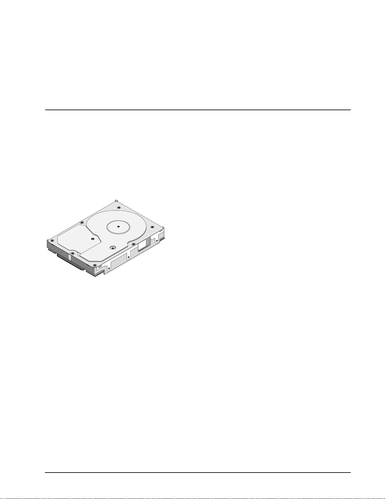
Figure 1. Cheetah 10K.7 SCSI family drive (ST3300007LC shown) . . . . . . . . . . . . . . . . . . . . . . . . . . . . 1
Figure 2. Typical ST3300007 drive +12 V current profile . . . . . . . . . . . . . . . . . . . . . . . . . . . . . . . . . . . 28
Figure 3. Typical ST3300007 drive +5 V current profile. . . . . . . . . . . . . . . . . . . . . . . . . . . . . . . . . . . . . 28
Figure 4. Typical ST3146707 drive +12 V current profile . . . . . . . . . . . . . . . . . . . . . . . . . . . . . . . . . . . 29
Figure 5. Typical ST3146707 drive +5 V current profile . . . . . . . . . . . . . . . . . . . . . . . . . . . . . . . . . . . . 29
Figure 6. Typical ST373207 drive +12 V current profile . . . . . . . . . . . . . . . . . . . . . . . . . . . . . . . . . . . . 30
Figure 7. Typical ST373207 drive +5 V current profile. . . . . . . . . . . . . . . . . . . . . . . . . . . . . . . . . . . . . . 30
Figure 8. ST3300007 DC current and power vs. input/output operations per second (SE) . . . . . . . . . 31
Figure 9. ST3300007 DC current and power vs. input/output operations per second (LVD). . . . . . . . . 31
Figure 10. ST3146707 DC current and power vs. input/output operations per second (SE) . . . . . . . . . 32
Figure 11. ST3146707 DC current and power vs. input/output operations per second (LVD). . . . . . . . . 32
Figure 12. ST373207 DC current and power vs. input/output operations per second (SE) . . . . . . . . . . 33
Figure 13. ST373207 DC current and power vs. input/output operations per second (LVD). . . . . . . . . . 33
Figure 14. Location of the HDA temperature check point . . . . . . . . . . . . . . . . . . . . . . . . . . . . . . . . . . . . 34
Figure 15. Recommended mounting . . . . . . . . . . . . . . . . . . . . . . . . . . . . . . . . . . . . . . . . . . . . . . . . . . . . 36
Figure 16. LW mounting configuration dimensions . . . . . . . . . . . . . . . . . . . . . . . . . . . . . . . . . . . . . . . . . 39
Figure 17. LC mounting configuration dimensions. . . . . . . . . . . . . . . . . . . . . . . . . . . . . . . . . . . . . . . . . . 40
Figure 18. J6 jumper header . . . . . . . . . . . . . . . . . . . . . . . . . . . . . . . . . . . . . . . . . . . . . . . . . . . . . . . . . . 46
Figure 19. J5 jumper header (on LW models only) . . . . . . . . . . . . . . . . . . . . . . . . . . . . . . . . . . . . . . . . . 47
Figure 20. J2 option select header (on LW models only). . . . . . . . . . . . . . . . . . . . . . . . . . . . . . . . . . . . . 48
Figure 21. Air flow (suggested) . . . . . . . . . . . . . . . . . . . . . . . . . . . . . . . . . . . . . . . . . . . . . . . . . . . . . . . . 50
Figure 22. LW model drive physical interface (68-pin J1 SCSI I/O connector) . . . . . . . . . . . . . . . . . . . . 66
Figure 23. LC model drive physical interface (80-pin J1 SCSI I/O connector). . . . . . . . . . . . . . . . . . . . . 66
Figure 24. SCSI daisy chain interface cabling for LW drives . . . . . . . . . . . . . . . . . . . . . . . . . . . . . . . . . . 71
Figure 25. Nonshielded 68-pin SCSI device connector used on LW drives . . . . . . . . . . . . . . . . . . . . . . 72
Figure 26. Nonshielded 80-pin SCSI “SCA-2” connector, used on LC drives . . . . . . . . . . . . . . . . . . . . . 73
Figure 27. Typical SE-LVD alternative transmitter receiver circuits. . . . . . . . . . . . . . . . . . . . . . . . . . . . . 81
Cheetah 10K.7 SCSI Product Manual, Rev. D vii

viii Cheetah 10K.7 SCSI Product Manual, Rev. D
1.0 Scope
This manual describes Seagate® Technology LLC, Cheetah® 10K.7 SCSI disc drives.
Cheetah 10K.7 SCSI driv es support the small computer system interface (SCSI) as described in the ANS I
SCSI SPI-3 interface specifications to the extent described in this manual. The SCSI Interface Product Manual
(part number 75789509) descr ibes general SCSI interface charac te rist ic s of thi s an d othe r famil ies of Se agate
drives.
From this point on in this product ma nual the reference to Chee tah 10K.7 SCSI models is referr ed to as “the
drive” unless references to individual models are necessary.
Figure 1. Cheetah 10K.7 SCSI family drive (ST3300007LC shown)
Cheetah 10K.7 SCSI Product Manual, Rev. D 1

2 Cheetah 10K.7 SCSI Product Manual, Rev. D

2.0 Applicable standards and reference documentation
The drive has been developed as a system peripheral to the highest standards of design and construction. The
drive depends upon its host equ ipment to provide adequate power and envi ronment in order to achi eve opti-
mum performance and co mpliance with applicable indus try and governmental regulations. Special attention
must be given in the areas of safety, power distribution, shielding, audible noise control, and temperature regu-
lation. In particula r, the drive must b e s ecur el y mou nted i n o rde r to gua ra nte e th e s pe ci fie d p er formance char-
acteristics. Mounting by bottom holes must meet the requirements of Section 8.4.
2.1 Standards
The Cheetah 10K.7 SC SI fa mily c ompli es w ith Seag ate standards as note d in the approp riate sectio ns o f this
Manual and the Seagate SCSI Interface Product Manual, part number 75789509.
The Cheetah 10K.7 SCSI disc drive is a UL recognized c omponent per UL 1950, CSA certi fied to CSA C22. 2
No. 950-95, and VDE certified to VDE 0805 and EN60950.
2.1.1 Electromagnetic compatibility
The drive, as delivered , is designed for system integrati on and installation into a suitable encl osure prior to
use. As such the d rive is supplied as a subassembly and is not subject to Subpart B of Part 15 of the FCC
Rules and Regulation s nor the Radio Interference Reg ulations of the Canadian Departm ent of Communica-
tions.
The design characteristics of the drive serve to minimize radiation when installed in an enclosure that provides
reasonable shielding. As such, the drive is capable of meeting the Class B limits of the FCC Rules and Regula-
tions of the Canadian Department of Communications when properly packaged. However, it is the user’s
responsibility t o assure that the drive mee ts the appropriate EMI re quirements in their system. S hielded I/O
cables may be requir ed if the en closure do es not provi de adequate shieldi ng. If the I/O cab les are exte rnal to
the enclosure, shielded cables should be used, with the shields grounded to the enclosure and to the host con-
troller.
2.1.2 Electromagnetic susceptibility
As a component a ssembly, the drive is not requ ired to meet any susc eptibi lity perfor mance requ irements. It is
the responsibilit y of those integrating the dr iv e wit hin the ir s y ste ms to perform those tests re q uire d a nd des ig n
their system to ensure th at equipment operating in the same sy stem as the drive or external to the syste m
does not adversely affect the performance of the drive. See Table 2, DC power requirements.
Cheetah 10K.7 SCSI Product Manual, Rev. D 3

2.2 Electromagnetic compliance
Seagate uses an indepe ndent laboratory to co nfirm compliance to the di rectives/standard(s) for CE Marking
and C-Tick Marking. The drive was tested in a representative system for typical applications. The selected system represents the most popular characteristics for test platforms. The system configurations include:
• Typical current use microprocessor
• 3.5-inch floppy disc drive
• Keyboard
• Monitor/display
• Printer
• External modem
•Mouse
Although the test system with this Seagate model complies to the directives/standard(s), we cannot guarantee
that all systems will comply. The computer manufacturer or system integrator shall confirm EMC compliance
and provide CE Marking and C-Tick Marking for their product.
Electromagnetic compliance for the European Union
If this model has the CE Marking it co mplies with the European Union requirements of the El ectromagnetic
Compatibility Directive 89 /336/EEC of 03 May 1989 as amend ed by Dir ective 92 /31/ EEC of 28 Apri l 1992 an d
Directive 93/68/EEC of 22 July 1993.
Australian C-Tick
If this model has th e C-Tick Marking it complies with the Austr alia/New Zeal and Standard AS/NZS3548 199 5
and meets the Electromagnet ic Compatibility (EMC) Framework requi rements of Australia’s Spectrum Management Agency (SMA).
Korean MIC
If this model has the Korean Ministry of Information and Communication (MIC) logo, it complies with paragraph
1 of Article 11 of the Electromagnetic Compatibility (EMC) Control Regulation and meets the Electroma gnetic
Compatibility Framework requirements of the Radio Research Laborator y (RRL) Ministry of Information and
Communication Republic of Korea.
Taiwanese BSMI
If this model has the Chinese National Standard (CNS) 13438 marking, it complies with Chinese National Standard (CNS) 13438 an d meets the Electromagnetic Compatibil ity (EMC) Framework requ irements of the Taiwanese Bureau of Standards, Metrology, and Inspection (BSMI).
2.3 European Union Restriction of Hazardous Substances (RoHS)
A new law, the European Union Restri ction of Hazardous Substances (RoHS) di rective, will res trict the presence of chemical subs tances, including Lead (Pb), in el ectronic products effective Ju ly 2006. The directive’s
requirements have not been finalized. This drive is manufactured with components and materials that are
expected to comply with the RoHS directive when the directive takes effect.
4 Cheetah 10K.7 SCSI Product Manual, Rev. D

2.4 Reference documents
Cheetah 10K.7 SCSI Installation Guide Seagate P/N 100260917
Safety and Regulatory Agency Specifications Seagate P/N 75789512
SCSI Interface Product Manual Seagate P/N 75789509
Applicable ANSI small computer system interface (SCSI) document numbers:
T10/1143D Enhanced SCSI Parallel Interface (EPI)
T10/1416D Primary Commands-2 (SPC-3)
T10/1417D SCSI Block Commands (SBC-2)
T10/1157D SCSI Architectural Model-2 (SAM-2)
T10/1302D SPI-3 (SCSI Parallel Interface version 3)
T10/1365D SPI-4 (SCSI Parallel Interface version 4)
SFF-8451 Specification for SCA-2 Unshielded Connections
Package Test Specification Seagate P/N 30190-001 (under 100 lb.)
Package Test Specification Seagate P/N 30191-001 (over 100 lb.)
Specification, Acoustic T est Requirements, and Procedures Seagate P/N 30553-001
In case of conflict between this document and any referenced document, this document takes precedence.
Cheetah 10K.7 SCSI Product Manual, Rev. D 5

6 Cheetah 10K.7 SCSI Product Manual, Rev. D
3.0 General description
Cheetah 10K.7 SCSI dr ives combine giant magnetoresistive (GMR) heads, partial respon se/maximum likeli-
hood (PRML) read channel electr onics, embedded servo technology, and a wide Ultra320 SCSI interface to
provide high performa nce, hi gh ] data stor age for a varie ty of s ystem s including engineering wor k statio ns , net-
work servers, mainframes, and supercomputers.
Ultra320 SCSI uses negotiated transfer rates. These transfer rates will occur only if your host adapter supports
these data transfer rates and is compatible with the required hardware requirements of the I/O circuit type. This
drive also operates at S CSI-1 and SCSI- 2 data tran sfer rat es for backw ard compatib ility with non- Ultra/ Ultra2/
Ultra320 SCSI host adapters.
Table 1 lists the features that differentiate the Cheetah 10K.7 SCSI models.
Table 1: Drive model number vs. differentiating features
Model number
ST3300007LW
ST3146707LW
ST373207LW
ST3300007LC
ST3146707LC
ST373207LC
Number of active
heads I/O circuit type [1]
8
4
Single-ended (SE) and low voltage differential (LVD) 68
2
8
4
Single-ended (SE) and low voltage differential (LVD) 80
2
Number of I/O
connector pins
[1] See Section 9.6 for details and definitions.
The drive records and recovers data on approximately 84 mm non-removable discs.
The drive supports the Small Computer System Interface (SCSI) as described in the ANSI SCSI interface
specifications to the extent desc ribed in th is m anual (v olume 1), whi ch d efines the produ ct pe rforman ce c har-
acteristics of the Cheetah 10K.7 SCSI family of drives, and the SCSI Interface Product Manual (volume 2), part
number 75789509, which desc ribes the general interface characteri stics of this and oth er families of Seagat e
SCSI drives.
The drive’s interface sup ports mul tip le ini tia tor s , disc onn ec t/r econn ec t, se lf- c onfig u ring h os t so ftware, a nd l og-
ical block addressing.
The head and disc assembly (HDA) is sealed at the factory. Air circulates within the HDA through a non-
replaceable filter to maintain a contamination-free HDA environment.
Never disassemble the HDA a nd do not at tempt to service ite ms in the sealed enclo su re (hea ds , m edi a, ac tu-
ator, etc.) as this requires specia l facilities. The d rive contains no replac eable parts. Opening the HDA voids
your warranty.
Cheetah 10K.7 SCSI Product Manual, Rev. D 7

Cheetah 10K.7 SCSI drives use a dedicated landing zone at the innermost radius of the media to eliminate the
possibility of d estroying or degrading d ata by landing in the data zone. The drive automatically goes to the
landing zone when power is removed.
An automatic shipping lock prevents potential damage to the heads and discs that results from movement during shipping and handl in g. T he s hip pin g lo ck auto mat ic all y dis eng age s whe n powe r i s ap plied to the drive and
the head load process begins.
A high-performance actuator assembly with a low-inertia, balanced, patented, straight-arm design provides
excellent performance with min im al powe r diss ipation .
3.1 Standard features
The Cheetah 10K.7 SCSI family has the following standard features:
• Integrated Ultra320 SCSI controller
• Multimode SCSI drivers and receivers—single-ended (SE) and low voltage differential (LVD)
• 16 bit I/O data bus
• Asynchronous and synchronous data transfer protocol
• Firmware downloadable via SCSI interface
• User-selectable logical block size (512 to bytes per logical block) in any multiple of four bytes
• Programmable sector reallocation scheme
• Flawed sector reallocation at format time
• Programmable auto write and read reallocation
• Reallocation of defects on command (post format)
• ECC maximum burst correction length of (320) bits
• Sealed head and disc assembly
• No preventative maintenance or adjustment required
• Dedicated head landing zone
• Embedded servo design
• Self diagnostics performed when power is applied to the drive
• Zoned bit recording (ZBR)
• Vertical, horizontal, or top down mounting
• Dynamic spindle brake
• 8,192 kbytes data buffer
• Hot plug compatibility (Section 9.6.4.2 lists proper host connector needed) for LC model drives
• Drive Self Test (DST)
• BackGround Media Scan (BGMS)
• Data Integrity Check
•Power Save
• Supports SCSI bus fairness
3.2 Media characteristics
The media used on the drive has an alumi num sub st rat e co ated with a thin fi lm magn eti c mater ia l, over coate d
with a proprietary protective layer for improved durability and environmental protection.
8 Cheetah 10K.7 SCSI Product Manual, Rev. D
3.3 Performance
• Supports industry standard Ultra320 SCSI interface
• Programmable multi-segmentable cache buffer (see Section 4.5)
• 10,000 RPM spindle. Average latency = (3.00) ms
• Command queuing of up to 64 commands
• Background processing of queue
• Supports start and stop commands (spindle stops spinning)
3.4 Reliability
• Annualized Failure Rate (AFR) of 0.62%
• LSI circuitry
• Balanced low mass rotary voice coil actuator
• Incorporates industry-standard Self-Monitoring, Analysis and Reporting Technology (S.M.A.R.T.)
• 5-year warranty
3.5 Formatted capacities
Standard OEM models are formatted to 512 bytes per block. The sector size is selectable at format time. Users
having the necessary equipm ent may mo dify the data block s ize before issuing a fo rmat comm and and obtain
different formatted capacities than those listed.
To provide a stable target capacity environment and at the same time provide users with flexibility if they
choose, Seagate recommends product planning in one of two modes:
1. Seagate designs specify capacity points at certain sector sizes that Seagate guarantees current and future
products will meet. We recommend custo mers use this capacity in their project pl anning, as it ensures a
stable operating point with bac kward and forwar d com patibility from gen eration to gener ation. The curren t
guaranteed operating points for this product are:
ST373207 ST3146707 ST3300007
Sector Size
Decimal Hex Decimal Hex Decimal Hex
512 143,374,744 88BB998 286,749,488 11177330 585,937,500 22ECB25C
514 141,025,384 867E068 282,050,768 10CFC0D0 574,712,644 22416B44
520 140,395,092 85E4254 280,790,184 10BC84A8 573,653,847 22314357
522 139,463,602 8500BB2 279,041,740 10A1D6CC 570,053,000 21FA5188
524 137,577,184 83342E0 275,154,368 106685C0 566,007,800 21BC97F8
528 557,874,778 21407E5A
2. Seagate drives also may be used at the maximum available capacity at a given sector size, but the excess
capacity above the guaranteed level will vary between 10K and 15K families and from generation to generation, depending on how each sector si ze actually for mats out for zone frequencies an d splits over serv o
bursts. This added capaci ty potent ial may range from 0.1 to 1.3 percent above th e guarant eed capacities
listed above. Us ing th e dr ives in th is mann er gi ves the ab so lute m aximu m capacity poten tial, but the user
must determine if the extra ca pacity potential is useful, or whether their assurance of backward and forward compatibility takes precedenc e.
Cheetah 10K.7 SCSI Product Manual, Rev. D 9

3.5.1 Programmable drive capacity
Using the Mode Select command, the drive can change its capacity to something less than maximum. See the
Mode Select Parameter List table in the SCSI Interface Product Manual. Refer to the Parameter list block
descriptor number of blocks field. A value of zero in the number of blocks field indicates that the drive shall not
change the capacity it i s currently forma tted to have. A number in the n umber of block s field that is less than
the maximum numbe r of LBAs changes th e total driv e capacity t o the val ue in the block des criptor number of
blocks field. A value greater than the maximum number of LBAs is rounded down to the maximum capacity.
3.6 Factory installed accessories
OEM Standard drives are shipped with the Cheetah 10K.7 SCSI Installation Guide, part number 100260917,
and the Safety a nd Regulatory Agency Spec ifications, part number 75789512 (unless otherwise specified) .
The factory also ships with the drive a small bag o f jumper plugs used for the J2, J5, and J6 option select
jumper headers on LW models only.
3.7 Options (factory installed)
All customer req uested options are inc orporated during produ ction or packaged at t he manufacturing facil ity
before shipping. Some of the options available are (not an exhaustive list of possible options):
• Other capacities can be ordered depending on sparing scheme and sector size requested.
• Single unit shipping pack. The drive is normall y shipped in bulk packagin g to provide maximum pro tection
against transit damage. Units shipped individually require additional protection as provided by the single unit
shipping pack. Users planning single unit distribution should specify this option.
• The Cheetah 10K.7 SCSI Installation Guide, part number 100260917, is usually included with each standard
OEM drive shipped, but extra copies may be ordered.
• The Safety and Regulatory Agency Specifications, part number 75 789512, is usually included with e ach
standard OEM drive shipped, but extra copies may be ordered.
3.8 Accessories (user installed)
The following accessories are available. All accessories may be installed in the field.
• Single unit shipping pack.
10 Cheetah 10K.7 SCSI Product Manual, Rev. D

4.0 Performance characteristics
4.1 Internal drive characteristics ( transparent to user)
ST3300007 ST3146707 ST373207
Drive capacity 300.0 146.8 73.4 GByte (formatted, rounded off values)
Read/write heads 8 4 2
Bytes/track 556 556 556 Kbytes (average, rounded off values)
Bytes/surface 50.5 50.5 50.5 Gbytes (unformatted, rounded off values)
Tracks/surface (total) 90,774 90,774 90,774 Tracks (user accessible)
Tracks/inch 105,000 105,000 105,000 TPI
Peak bits/inch 658 658 658 KBPI
Internal data rate 470 - 944 470 - 944 470 - 944 Mbits/sec (variable with zone)
Disc rotational speed 10,000 10,000 10,000 r/min
Average rotational latency 3.00 3.00 3.00 msec
4.2 SCSI performance characteristics (visible to user)
The values given in Section 4.2.1 apply to all models of the Cheetah 10K.7 SCSI family unless otherwise specified. Refer to Section 9.10 and to the SCSI Interface Product Manual for additional timing details.
Cheetah 10K.7 SCSI Product Manual, Rev. D 11

4.2.1 Access time [4]
Not including controller overhead
(without disconnect) [1]
(ST3300007 data shown)
Drive level
Read Write
msec
Average—Typical [2] 4.9 5.4
Single Track—Typical [2] 0.45 0.65
Full Stroke—Typical [2] 9.9 10.5
4.2.2 Format command execution time (minutes) [1]
ST3300007 ST3146707 ST373207
Maximum (with verify) 200 100 50
Maximum (no verify) 100 50 25
4.2.3 Generalized performance characteristics
Minimum sector interleave 1 to 1
Data buffer transfer rate to/from disc media (one 512-byte sector):
ST3300007 ST3146707 ST373207
Minimum* 59 59 59 MBytes/sec
Maximum 118 118 118 MBytes/sec
Sustainable disc transfer rate:
ST3300007 ST3146707 ST373207
Minimum* 39 39 39 MBytes/sec
Maximum 80 80 80 MBytes/sec
Note. 1 Megabyte (MB) = 1,000,000 bytes.
SCSI interface data transfer rate (asynchronous):
Maximum instantaneous one byte wide 5.0 Mbytes/sec [3]
Maximum instantaneous two bytes wide 10.0 Mbytes/sec [3]
Synchronous transfer rate Ultra320 SCSI
In low voltage differential (LVD) interface mode 5.0 to 320 Mbytes/sec
Sector Sizes:
Default 512 byte user data blocks
12 Cheetah 10K.7 SCSI Product Manual, Rev. D

Variable 512 to 528 bytes per sector in even number of bytes per sector.
If n (number of bytes per sector) is odd, then n-1 will be used.
Read/write consecutive sectors on a track Yes
Flaw reallocation performance impact (for flaws reallocated at format time using
the spare sectors per sparing zone reallocation scheme.)
Average rotational latency 3.0 msec
Notes for Section 4.2.
[1] Execution time measu red from receipt of the last by te of the Command Descriptor B lock (CDB) to the
request for a Status Byte Transfer to the Initiator (excluding connect/disconnect).
[2] Typical access times are measured u nder nom inal condi tions of te mpera ture, v oltage, and ho rizontal or i-
entation as measured on a representative sample of drives.
[3] Assumes system ability to support the rates listed and no cable loss.
[4] Access to data = access time + latency time.
Negligible
4.3 Start/stop time
After DC power at nomi nal voltage h as been ap plied, th e drive becom es rea dy withi n 25 se conds if the Mo tor
Start Option is disabled (i.e. the motor sta rts as soon as the power has be en applied). If a rec overable error
condition is detected during the start sequence, the drive executes a recovery procedure which may cause the
time to become ready to exceed 25 se conds. During spi n up to ready tim e the drive responds to some commands over the SCSI interface in less than 3 seconds after application of power. Stop time is 30 seconds from
removal of DC power.
If the Motor Start Option is enabled , the interna l contro ller acc epts the command s liste d in the S CSI Inter face
Product Manual less than 3 seconds after DC power has been appli ed. After the Motor Start Command has
been received the dri ve becomes re ady for norma l operations withi n 25 second s typically (excluding a n error
recovery procedur e). The Motor Start Command can also be u sed to command t he drive to stop the spi ndle
(see the SCSI Interface Product Manual).
There is no power control switch on the drive.
4.4 Prefetch/multi-segmented cache control
The drive provides prefetch (read look-ahead) and multi-segmented cache control algorithms that in many
cases can enhance system performance. “Cache” as used herein refers to the drive buffer storage space when
it is used in cache operations. To select prefetch and cache features the host sends the Mode Select command
with the proper v alues in the applicabl e bytes in Mode Page 08h (see the SCSI Interf ace Product Manual).
Prefetch and cache ope ration are independent fe atur es fr om the s tandpoint tha t ea ch is enabled and disabled
independently via the Mode Select command. However, in actual operation the prefetch feature overlaps
cache operation somewhat as is noted in Section 4.5.1 and 4.5.2.
All default cache and prefetch Mode paramete r values (Mode Page 08 h) for standard OEM versions of this
drive family are given in Tables 7, 8, and 9.
4.5 Cache operation
In general, 6,991 kbytes of the physical buffer space in the drive can be used as storage space for cache operations. The buffer can be d ivided into logical segments (Mode Selec t Page 08h, byte 13) from which data is
read and to which data is written. The drive supports a maximum of 64 cache segments. The drive maintains a
table of logical block dis c medium a ddres ses of th e data stored i n eac h segm ent of the buffer. If cache operation is enabled (RCD bit = 0 in Mode Page 08h, byte 2, bit 0. See SCSI Interface Product Manual), data
requested by the hos t with a Read command i s r etr ie ve d fro m the bu ffer (if i t i s th er e), b efo re an y di sc ac ce ss
Cheetah 10K.7 SCSI Product Manual, Rev. D 13

is initiated. If c ache oper ation is no t enabl ed, the buffer (stil l se gmented with r equired num ber of s egments) is
still used, but only as circular buffer segments during disc medium read operations (disregarding Prefetch
operation for the momen t). That is, the drive does not check in the buffer segments for the requested read
data, but goes directly to the medium to retrieve it. The retrieved data merely passes through some buffer segment on the way to the h ost. On a ca che mis s, all data transfe rs to the hos t are in acc ordance wi th buffer-full
ratio rules. On a cache h it the dr ive igno res the buffer-full r atio rules . See e xplanations associa ted with Mode
page 02h (disconnect/reconnect control) in the SCSI Interface Product Manual.
The following is a simplified description of a read operation with cache operation enabled:
Case A - A Read command is received and the first logical block (LB) is already in cache:
1. Drive transfers to the initiator the first LB requested plus all subsequent contiguous LBs that are already in
the cache. This data may be in multiple segments.
2. When the requested LB is reached that is not in any cache segment, the drive fetches it and any remaining
requested LBs from th e disc and puts them in a segment of the c ache. The drive transfers the rem aining
requested LBs from the ca che to t he host in accorda nce with the disconn ect/r econn ect speci fication mentioned above.
3. If the prefetch feature is enabled, refer to Section 4.5.2 for operation from this point.
Case B - A Read command requests data, the first LB of which is not in any segment of the cache:
1. The drive fetches the requested LBs from the disc and transfers them into a segm ent, and from there to
the host in accordance with the disconnect/reconnect specification referred to in case A.
2. If the prefetch feature is enabled, refer to Section 4.5.2 for operation from this point.
Each buffer segment is act ually a self-containe d circular sto rage (wrap-arou nd occurs), the length of which is
an integer number sectors. The wrap-around capability of the individual segments greatly enhances the
buffer’s overall performance as a cache storage, allowing a wide range of user selectable configurations, which
includes their use in the prefetch operat ion (if enabled) , even when cache ope ration is disab led (see Section
4.5.2). The number of segmen ts is set dyna mically by the dri ve and can not norm ally be s et by the h ost (it ca n
be set using the PM bit as describe d in Section 4.5.3). The siz e in Kbytes of each segmen t is not reported by
the Mode Sense command page 08h, bytes 14 and 15. The value 0XFFFF is always reported. If a size specification is sent by the ho st in a M ode Select c ommand (byte s 14 and 15) no new segm ent si ze is set up b y the
drive, and if the STRICT bit in Mode page 00h (byte 2, bit 1) is set to one, the drive responds as it does for any
attempt to change unchangeable parameters (see SCSI Interface Product Manual).
4.5.1 Caching write data
Write caching is a write operation by the drive th at mak es use of a drive buffer sto ra ge ar ea where the da ta t o
be written to the medium is stored in one or more segments while the drive performs the write command.
If read caching is enabled (RCD=0), then data written to the medium is retained in the cache to be made available for future read cache h its. The same buffer space an d segme ntation is use d as set up for read functions .
The buffer segmentation s cheme is set up or changed independently, having nothing to do with the state of
RCD. When a write command is issued, i f RCD=0, the cache is first checke d to see if any logical blocks tha t
are to be written are a lready stored in the cache f rom a previous read or write comman d. If there are, the
respective cache segments are cleared. The new data is cached for subsequent Read commands.
If the number of write data logi cal block s exceeds th e size of the s egment being wr itten into, whe n the end of
the segment is reached, the data is written into the beginning of the same cache segment, overwriting the data
that was written there at the beginning of the operation. However, the drive does not overwrite data that has not
yet been written to the medium.
14 Cheetah 10K.7 SCSI Product Manual, Rev. D

If write caching is enabled (WCE=1), t hen the drive may return GOOD status on a write command a fter the
data has been transferred into the cache, but before the data has been written to the medium. If an error
occurs while writing the data to the medium, and GOOD status has already been returned, a deferred error will
be generated.
The Synchronize Cache command may be used to force the drive to write all cached write data to the medium.
Upon completion of a Synchronize Cache command, all data received from previous write commands will have
been written to the medium.
Tables 7, 8, and 9 show Mode default settings for the drives.
4.5.2 Prefetch operation
If the Prefetch fea ture i s ena bl ed, data in co nti guo us lo gi cal b lock s on t he d is c immediately beyond tha t whi ch
was requested by a Read command can be re trieved and stored in the buffer for i mmediate transfer from the
buffer to the host on subsequ ent Read com mands that request t hose logica l block s (this is tr ue even if cache
operation is disabled). Though the prefetch operation uses the buffer as a cache, finding the requested data in
the buffer is a prefetch hit, not a cache operation hit. Prefetch is enabled using Mode Select page 08h, byte 12,
bit 5 (Disable Read Ahead - DRA bit). DRA bit = 0 enables prefetc h. Since data that is pre fetched replaces
data already in some buffer segment(s ), the hos t can lim it the amou nt of pr efet ch data to optimi z e syst em per formance. The max prefetch field (bytes 8 a nd 9) limits the amount of pref etch. The drive does not use the
Prefetch Ceiling field (bytes 10 and 11).
During a prefetch operati on, the dri ve crosses a cylinde r boundary to fetch mor e data only if th e Discontinu ity
(DISC) bit is set to one in bit 4 of byte 2 of Mode parameters page 08h.
Whenever prefetch ( re ad loo k-ah ead) is enabled (ena ble d b y DRA = 0) , it operates under th e con t rol of A R LA
(Adaptive Read Look-Ahead). If the host uses software interleave, ARLA enables prefetch of contiguous
blocks from the disc when it senses that a prefetch hit will likely occur, even if two consecutive read operations
were not for physically con tiguou s blocks of da ta (e.g., “software i nterleave”) . ARLA disab les prefetc h when it
decides that a prefetch hit will not likely occur. If the host is not using software interleave, and if two sequential
read operations are no t for c ontigu ous bloc ks of data, ARLA d isables prefetc h, but as long as se quentia l read
operations request contiguous blocks of data, ARLA keeps prefetch enabled.
4.5.3 Optimizing cache performance for desktop and server applications
Desktop and server applications require different drive caching operations for optimal performance. This
means it is difficult to provide a single configuration that meets both of these needs. In a desktop environment,
you want to con figure the cache to respond q uickly to repetitive ac cesses of multiple s mall segmen ts of data
without taking the time to “look ahea d” to the next conti guous segmen ts of data. In a server environ ment, you
want to configure the cac he to provide large volumes of seque ntial data in a non-repetitive manner. In this
case, the ability of the cache to “look ahead” to the next contiguous segmen ts of sequential data is a good
thing.
The Performance Mode (PM) bit contr ols the way the drive switches the cache buffer into different modes o f
segmentation. In “server mode” (PM bit = 0), the drive can dynamically cha nge the number of cache buffer
segments as needed to opt imize the performa nce, based on the command st ream from the hos t. In “desktop
mode” (PM bit = 1), the number of segments is maintained at the value defined in Mode Page 8, Byte 13, at all
times (unless changed by using a Mode Select command). For additional information about the PM bit, refer to
the Unit Attention Param eters page (00h) of the Mode Sense command (1Ah) in the SCSI Interfac e Product
Manual, part number 75789509.
Cheetah 10K.7 SCSI Product Manual, Rev. D 15

16 Cheetah 10K.7 SCSI Product Manual, Rev. D

5.0 Reliability specifications
The following reliabi lity specifications assume cor rect host/drive operational interfa ce, including all interface
timings, power supply voltages, environmental requirements and drive mounting constraints (see Section 8.4).
Seek Errors
Less than 10 in 10
Read Error Rates [1]
Recovered Data Less than 10 errors in 10
Unrecovered Data Less than 1 sector in 10
Miscorrected Data Less than 1 sector in 10
AFR 0.62%
Service Life 5 years
Preventive Maintenance None required
Note.
[1] Error rate specified with automatic retries and data correction with ECC enabled and all flaws reallocated.
5.1 Error rates
The error rates stated in this specification assume the following:
• The drive is operated per this specification using DC power as defined in this manual (see Section 6.2).
• Errors caused by host system failures are excluded from error rate computations.
• Assume random data.
• Default OEM error r ecovery settings are applied. Thi s includes AWRE, ARRE, full read retries, fu ll write
retries and full retry time.
8
seeks
12
bits transferred (OEM default settings)
15
bits transferred (OEM default settings)
21
bits transferred
5.1.1 Recoverable Errors
Recovereable errors are those detected and corrected by the drive, and do not require user intervention.
Recoverable Data errors will use co rrection, although ECC on -the-fly is not considered for purposes of recov-
ered error specifica tio ns.
Recovered Data error rate is determine d using read bits transfer red for recove rable errors occurring dur ing a
read, and using write bits transferred for recoverable errors occurring during a write.
5.1.2 Unrecoverable Erro rs
Unrecoverable Data Error s (Sense Ke y = 03h) ar e specified at l ess than 1 se ctor in erro r per 10
15
bits trans-
ferred. Unrecoverable Data Errors resulting from the same cause are treated are 1 error for that block.
Cheetah 10K.7 SCSI Product Manual, Rev. D 17

5.1.3 Seek errors
A seek error is defined as a fail ur e of the dr i ve to pos it ion the heads to the addressed t rack . After dete cti ng a n
initial seek error, the drive automatically performs an error recovery process. If the error recovery process fails,
a seek positioning error (Error code = 15h or 02h) will be reporte d with a Hardware error (04h) in t he Sense
Key. Re coverab le seek errors ar e spec ified at Less than 10 er rors in 10
8
seeks. Unrecoverable seek errors
(Sense Key = 04h) are classified as drive failures.
5.2 Reliability and service
You can enhance the reliability of Cheetah 10K.7 SCSI disc dr ives by ensuring that the dr ive receives adequate cooling. S ection 6.0 provides temperature measurements and other informa tion that may be used to
enhance the service life of the drive. Section 8.3 provides recommended air-flow information.
5.2.1 Annualized Failure Rate (AFR)
The production disc dr ive shall achieve an AFR of 0.62% when oper ated in an environm ent that ensures th e
HDA case temperatur es spec ified in Sectio n 6. 4 are not exce eded. S hort -term ex cursi ons u p to th e spec ification limits of the operating e nvironment will not affect AFR perfor mance. Continual or sustained operation at
case temperatures above the values shown in Section 6.4.1 may degrade product reliability.
Estimated power-on operation hours means power-up hours per disc drive times the total number of disc
drives in service. Ea ch dis c drive shall h ave accu mulate d at le ast nine months of operatio n. Data sha ll be ca lculated on a rolling average base for a minimum period of six months.
AFR is based on the following assumption s:
• 8,760 power-on hours per year.
• 250 average on/off cycles per year.
• Operations at nominal voltages.
• Systems will prov ide adequate coolin g to ensure the case temperatures specified in Sec tion 6.4.1 are not
exceeded.
Drive failure means any stoppage or substandard performance caused by drive malfunction.
A S.M.A.R.T. predi ctive fail ure in dicat es that the dri ve is deter iorat ing to an imm inent fai lure and is consi dere d
an AFR hit.
5.2.2 Preventive maintenance
No routine scheduled preventive maintenance shall be required.
5.2.3 Hot plugging Cheetah 10K.7 SCSI disc drives
The ANSI SPI-3 (T10/13 02D) document defines the physical requir ements for removal and insertion of SCSI
devices on the SCSI bus. Four cases are addressed. The cases are differentiated by the state of the SCSI bus
when the removal or insertion occurs .
Case 1 - All bus devices powered off during removal or insertion
Case 2 - RST signal asserted continuously during removal or insertion
Case 3 - Current I/O processes not allowed during insertion or removal
Case 4 - Current I/O process allowed during insertion or removal, except on the device being changed
18 Cheetah 10K.7 SCSI Product Manual, Rev. D

Seagate Cheetah 10K.7 SCSI disc drives support all four hot plugging cases . Provision shall be made by the
system such tha t a dev ice being inserted makes p ower a nd g ro und c onn ect ion s pr ior to the connection of any
device signal co ntact to the bus. A device bein g removed shall maintain p ower and grou nd connecti ons after
the disconnection of any device signal contact from the bus (see SFF-8451 Specification for SCA-2 Unshielded
Connections).
It is the responsibility of the systems integrator to assure that no hazards from temperature, energy, voltage, or
ESD potential are presented during the hot connect/disconnect operation.
All I/O processes for th e SCSI device bein g inserted or remov ed shall be quiesc ent. All SCSI devices on the
bus shall have receivers that conform to the SPI-3 standard.
If the device being hot plugged uses single-ended (SE) drivers and the bus is currently operating in low voltage
differential (LVD) mode, then all I/O processes fo r all dev ices on the bus must be compl eted, an d the bus quiesced, before attempting to hot plug. Following the insertion of the newly installed device, the SCSI host
adapter must issue a Bus Reset, fol lowed by a sy nchronous transfer ne gotiation . Failure to per form the SCSI
Bus Reset could result in erroneous bus operations.
The SCSI bus termination and termination power source shall be external to the device being inserted or
removed.
End users shoul d not mix devices with high vol tage differential (HVD) driv ers and r eceivers a nd devices with
SE, LVD, or multimode drivers and receivers on the same SCSI bu s since the comm on mode vo ltages in the
HVD environment may not be controlled to safe levels for SE and LVD devices (see ANSI SPI-3).
The disc drive s pindle must come to a complete s top prior to completely removing the drive from the cabine t
chassis. Use of th e Stop Spindle command or partial withdr awal of the drive, e nou gh to b e disco nnecte d fro m
the power source, prior to removal are methods for insuring that this requirement is met. During drive insertion,
care should be taken to avoid exceeding the limits stated in Section 6.4.4, "Shock and vibration" in this manual.
5.2.4 S.M.A.R.T.
S.M.A.R.T. is an ac ronym for Se lf-Monitor ing Analys is and Reporti ng Technology. This technology is intended
to recognize conditions that indicate drive degradation and is designed to provide sufficient warning of a failure
to allow data back-up before an actual failure occurs.
Note. The firmwa re will monitor s pecific attribute s for degradation over time but canno t predict instanta-
neous drive failures.
Each attribute monit ors a specif ic set of co nditions in the operating pe rformance of the drive, and the thresholds are optimized to minimize “false” predictions.
Controlling S.M.A.R.T.
The operating mode of S.M .A.R.T. is controlled by the DEXCPT bit and the PERF bit of the “Informational
Exceptions Control Mo de Page” (1Ch) . The DEXCPT bit i s used to ena ble or dis able the S .M.A.R.T. process.
Setting the DEXCPT bit will disable all S.M.A.R.T. functions. When enabled, S.M.A.R.T . will collect on-line data
as the drive performs normal read/w rite oper ation s. When th e PERF bit is s et, the drive i s consi dered to b e in
“On-line Mode Only” and will not perform off-line functions.
The process of measuring off-line attributes and saving data can be forced by the Rezero Unit command. Forcing S.M.A.R.T. will reset the timer so that the next scheduled interrupt will be two hours.
The drive can be interrogated by the host to determine the time remaining before the next scheduled measurement and data logging process will occu r. This is accomplished by a log sense command to log page 0x3E.
The purpose is to allow the customer to control when S.M.A.R.T. interruptions occur. As described above, forcing S.M.A.R.T by the Rezero Unit command will reset the timer.
Cheetah 10K.7 SCSI Product Manual, Rev. D 19

Performance impact
S.M.A.R.T . attribute data will be saved to the disc for the purpose of recreating the events that caused a predictive failure. The driv e wi ll measure and save parameters on ce ev ery two hours subject to an idle period on the
SCSI bus. The process of measu ring off-line attribute data and saving data to the disc is uninterruptable and
the maximum delay is summarized below:
Maximum processing delay
On-line only delay Fully enabled delay
S.M.A.R.T. delay times 60 milliseconds 370 milliseconds
DEXCPT = 0, PERF = 1 DEXCPT = 0, PERF = 0
Reporting control
Reporting is contr olled in the Inform ational Exceptions Control Page (1Ch). Subject to the repo rting method,
the firmware will report a predicti ve 01-5D 00 sens e code. Th e error code is pr eserv ed through bus re sets and
power cycles.
Determining rate
S.M.A.R.T. monitor s the rate at which err ors occ ur and sign als a pred ictive fai lure if the rate of degr aded err or
rate increases to an un acce ptab le le ve l. To determine rate, error events are logged and compar ed to the number of total operations for a given attribut e. The interval defines the number of operatio ns over which to measure the rate. The counter that kee ps track of the current number of oper ations is referred to as the Interval
Counter.
S.M.A.R.T. measu res error rate, hence for each attribute th e occurrence of an error is recorded . A counter
keeps track of the number of errors for the current interval. This counter is referred to as the Failure Counter.
Error rate is simply the number of errors per s et of operations. The al gorithm that S.M.A.R. T. uses to record
rates of error is to s et th r esh ol ds for th e n umb er of erro rs a nd t he i nte rval . If the number of errors ex ce eds th e
threshold before the interval expires, then the error rate is considered to be unacceptable. If the number of
errors does not exceed the threshold before the interval expires, then the error rate is considered to be acceptable. In either case, the interval and failure counters are reset and the process starts over.
Predictive failures
S.M.A.R.T. signal s predic tive fai lures when the drive is perf orming una ccep tably for a period of tim e. The firmware keeps a running count of the number of times the error rate for each attribute is unacceptable. To accomplish this, a counter is incre mented wheneve r the error rate is unacc eptable and decremen ted (not to exceed
zero) whenever the error rate is acceptable. This counter is referred to as the Failure History Counter. There is
a separate Failure History Cou nter for each attribute. Should the counter continually be inc rem en ted suc h tha t
it reaches the predictive threshold, a predictive failure is signaled.
5.2.5 Thermal monitor
Cheetah 10K.7 SCSI drives implement a temperature warning system which:
1. Signals the host if the temperature exceeds a value which would threaten the drive.
2. Signals the host if the temperature exceeds a user-specified value.
3. Saves a S.M.A.R.T. data frame on the drive which exceed the threatening temperature value.
A temperature sensor monito rs the drive temperature and is sues a warning over the int erface when the temperature exceeds a s et threshol d. The temper ature is measured at power-up an d then at te n-minute intervals
after power-up.
20 Cheetah 10K.7 SCSI Product Manual, Rev. D
 Loading...