


OWNER’S MANUAL • Manual del usuario
Models / Modelos: SE-2254, SE-2352, SE-3000, SE-4020, SE-4022, SE-5025, SE-6030, SE-8050
Manual Battery Charger • Cargador de Batería Manual
ADVERTENCIA
•READ THE ENTIRE MANUAL BEFORE USING THIS PRODUCT. FAILURE TO DO SO CAN RESULT IN SERIOUS INJURY OR DEATH.
•LEA EL MANUAL COMPLETO ANTES DE UTILIZAR ESTE PRODUCTO. CUALQUIER FALLA PODRÍA RESULTAR EN SERIAS LESIONES O PODRÍA SER MORTAL.
00-99-001026/0210

Table of Contents
Section |
Page |
IMPORTANT SAFETY INSTRUCTIONS |
2 |
PERSONAL PRECAUTIONS |
2 |
PREPARING TO CHARGE |
3 |
CHARGER LOCATION |
4 |
DC CONNECTION PRECAUTIONS |
4 |
FOLLOW THESE STEPS WHEN BATTERY IS INSTALLED |
4 |
IN VEHICLE. |
|
FOLLOW THESE STEPS WHEN BATTERY IS OUTSIDE VEHICLE. 5 |
|
BATTERY CHARGING – AC CONNECTIONS |
5 |
ASSEMBLY INSTRUCTIONS |
6 |
CONTROL PANEL |
9 |
OPERATING INSTRUCTIONS |
10 |
CALCULATING CHARGE TIME |
12 |
MAINTENANCE INSTRUCTIONS |
15 |
STORAGE INSTRUCTIONS |
15 |
TROUBLESHOOTING |
15 |
BEFORE RETURNING FOR REPAIRS |
17 |
LIMITED WARRANTY |
18 |

ÍNDICE
SECCIÓN |
PÀGINA |
INSTRUCCIONES IMPORTANTES DE SEGURIDAD |
20 |
PRECAUCIONES PERSONALES |
21 |
PREPARACIÓN PARA LA CARGA |
21 |
UBICACIÓN DEL CARGADOR |
22 |
PRECAUCIONES DE CONEXIÓN EN CC |
22 |
SIGA ESTOS PASOS CUANDO LA BATERÍA ESTÉ COLOCADA |
|
EN EL VEHÍCULO. |
23 |
SIGA ESTOS PASOS CUANDO LA BATERÍA SE ENCUENTRE |
23 |
FUERA DEL VEHÍCULO. |
|
CARGA DE BATERÍA, CONEXIONES DE CA |
24 |
INSTRUCCIONES DE MONTAJE |
25 |
PANEL DE CONTROL |
28 |
INSTRUCCIONES DE OPERACIÓN |
29 |
CÁLCULO DE TIEMPO DE CARGA |
31 |
INSTRUCCIONES DE MANTENIMIENTO |
34 |
INSTRUCCIONES DE ALMACENAJE |
34 |
LOCALIZACIÓN Y SOLUCIÓN DE PROBLEMAS |
34 |
ANTES DE DEVOLVER A REPARACIONES |
37 |
GARANTÍA LIMITADA |
37 |

IMPORTANT: READ AND SAVE THIS SAFETY AND INSTRUCTION MANUAL.
SAVE THESE INSTRUCTIONS – The SE Line of Wheel Chargers offers a wide range of features to accommodate your needs. This manual will show you how to use your charger safely and effectively. Please read, understand and follow these instructions and precautions carefully, as this manual contains important safety and operating instructions. The safety messages used throughout this manual contain a signal word, a message and an icon.
The signal word indicates the level of the hazard in a situation.
Indicates an imminently hazardous situation which, if not avoided, will result in death or serious injury to the operator or bystanders.
Indicates a potentially hazardous situation which, if not avoided, could result in death or serious injury to the operator or bystanders.
Indicates a potentially hazardous situation which, if not avoided, could result in moderate or minor injury to the operator or bystanders.
Indicates a potentially hazardous situation which, if not avoided, could result in damage to the equipment or vehicle or property damage.
Safety messages in this manual contain two different type styles.
•Unnumbered type states the hazard.
•Numbered type states how to avoid the hazard.
The icon gives a graphical description of the potential hazard.
Pursuant to California Proposition 65, this product contains chemicals known to the State of California to cause cancer and birth defects or other reproductive harm.
• 1 •
1.IMPORTANT SAFETY INSTRUCTIONS
Risk of electric shock or fire.
1.1Keep out of reach of children.
1.2Do not expose the charger to rain or snow.
1.3Use only recommended attachments. Use of an attachment not recommended or sold by Schumacher® Electric Corporation may result in a risk of fire, electric shock or injury to persons or damage to property.
1.4To reduce the risk of damage to the electric plug or cord, pull by the plug rather than the cord when disconnecting the charger.
1.5An extension cord should not be used unless absolutely necessary. Use of an improper extension cord could result in a risk of fire and electric shock. If an extension cord must be used, make sure:
•That the pins on the plug of the extension cord are the same number, size and shape as those of the plug on the charger.
•That the extension cord is properly wired and in good electrical condition.
•That the wire size is large enough for the A.C. ampere rating of the charger as specified in Section 8.
1.6To reduce the risk of electric shock, unplug the charger from the outlet before attempting any maintenance or cleaning. Simply turning off the controls will not reduce this risk.
1.7Remove personal metal items such as rings, bracelets, necklaces and watches when working with a lead-acid battery. A lead-acid battery can produce a shortcircuit current high enough to weld a ring or the like to metal, causing a severe burn.
1.8Do not operate the charger with a damaged cord or plug; take it to a qualified service person. (Call customer service at: 1-800-621-5485.)
1.9Do not operate the charger if it has received a sharp blow, been dropped or otherwise damaged in any way; take it to a qualified service person. (Call customer service at: 1-800-621-5485.)
1.10Do not disassemble the charger; take it to a qualified service person when service or repair is required. Incorrect reassembly may result in a risk of fire or electric shock. (Call customer service at: 1-800-621-5485.)
2.PERSONAL PRECAUTIONS
Risk of explosive gases.
2.1Working in the vicinity of a lead-acid battery is dangerous. Batteries generate explosive gases during normal battery operation. For this reason, it is of utmost importance that you follow the instructions each time you use the charger.
•2 •

2.2To reduce the risk of a battery explosion, follow these instructions and those published by the battery manufacturer and the manufacturer of any equipment you intend to use in the vicinity of the battery. Review the cautionary markings on these products and on the engine.
2.3NEVER smoke or allow a spark or flame in the vicinity of a battery or engine.
2.4Be extra cautious to reduce the risk of dropping a metal tool onto the battery. It might spark or short-circuit the battery or other electrical part that may cause an explosion.
2.5Use this charger for charging LEAD-ACID batteries only. It is not intended to supply power to a low voltage electrical system other than in a starter-motor application. Do not use this battery charger for charging dry-cell batteries that are commonly used with home appliances. These batteries may burst and cause injury to persons and damage to property.
2.6NEVER charge a frozen battery.
2.7NEVER overcharge a battery.
3.PREPARING TO CHARGE
Risk of contact with battery acid. Battery acid is a highly corrosive sulfuric acid.
3.1Consider having someone close enough by to come to your aid when you work near a lead-acid battery.
3.2Have plenty of fresh water and soap nearby in case battery acid contacts your skin, clothing or eyes.
3.3Wear complete eye and body protection, including safety goggles and protective clothing. Avoid touching your eyes while working near the battery.
3.4If battery acid contacts your skin or clothing, immediately wash the area with soap and water. If acid enters your eye, immediately flood the eye with cold running water for at least 10 minutes and get medical attention right away.
3.5If battery acid is accidentally swallowed, drink milk, the whites of eggs or water. DO NOT induce vomiting. Seek medical attention immediately.
3.6If it is necessary to remove the battery from the vehicle to charge it, always remove the grounded terminal first. Make sure all of the accessories in the vehicle are off to prevent arcing.
3.7Be sure the area around the battery is well ventilated while the battery is being charged.
3.8Clean the battery terminals before charging the battery. During cleaning, keep airborne corrosion from coming into contact with your eyes, nose and mouth. Use baking soda and water to neutralize the battery acid and help eliminate airborne corrosion. Do not touch your eyes, nose or mouth.
3.9Add distilled water to each cell until the battery acid reaches the level specified by the battery manufacturer. Do not overfill. For a battery without removable cell caps, such as valve regulated lead acid batteries (VRLA), carefully follow the manufacturer’s recharging instructions.
3.10Read, understand and follow all instructions for the charger, battery, vehicle and any equipment used near the battery and charger. Study all of the battery manufacturer’s specific precautions while charging and recommended rates of charge.
•3 •
3.11Determine the voltage of the battery by referring to the vehicle owner’s manual and make sure that the output voltage selector switch is set to the correct voltage. If the charger has an adjustable charge rate, charge the battery in the lowest rate first.
3.12Make sure that the charger cable clips make tight connections.
4.CHARGER LOCATION
Risk of explosion and contact with battery acid.
4.1Locate the charger as far away from the battery as the DC cables permit.
4.2Never place the charger directly above the battery being charged; gases from the battery will corrode and damage the charger.
4.3Do not set the battery on top of the charger.
4.4Never allow battery acid to drip onto the charger when reading the electrolyte specific gravity or filling the battery.
4.5Do not operate the charger in a closed-in area or restrict the ventilation in any way.
5.DC CONNECTION PRECAUTIONS
5.1Connect and disconnect the DC output clips only after setting all of the charger switches to the “off” position and removing the A.C. plug from the electrical outlet. Never allow the clips to touch each other.
5.2Attach the clips to the battery and chassis, as indicated in sections 6 and 7.
6.FOLLOW THESE STEPS WHEN BATTERY IS INSTALLED IN VEHICLE.
A spark near the battery may cause a battery explosion. To reduce the risk of a spark near the battery:
6.1Position the A.C. and D.C. cables to reduce the risk of damage by the hood, door and moving or hot engine parts. NOTE: If it is necessary to close the hood during the charging process, ensure that the hood does not touch the metal part of the battery clips or cut the insulation of the cables.
6.2Stay clear of fan blades, belts, pulleys and other parts that can cause injury.
6.3Check the polarity of the battery posts. The POSITIVE (POS, P, +) battery post usually has a larger diameter then the NEGATIVE (NEG, N, -) post.
6.4Determine which post of the battery is grounded (connected) to the chassis. If the negative post is grounded to the chassis (as in most vehicles), see step
6.5.If the positive post is grounded to the chassis, see step 6.6.
6.5For a negative-grounded vehicle, connect the POSITIVE (RED) clip from the battery charger to the POSITIVE (POS, P, +) ungrounded post of the battery. Connect the NEGATIVE (BLACK) clip to the vehicle chassis or engine block away from the battery. Do not connect the clip to the carburetor, fuel lines or sheet-metal body parts. Connect to a heavy gauge metal part of the frame or engine block.
•4 •
6.6For a positive-grounded vehicle, connect the NEGATIVE (BLACK) clip from the battery charger to the NEGATIVE (NEG, N, -) ungrounded post of the battery. Connect the POSITIVE (RED) clip to the vehicle chassis or engine block away from the battery. Do not connect the clip to the carburetor, fuel lines or sheetmetal body parts. Connect to a heavy gauge metal part of the frame or engine block.
6.7When disconnecting the charger, turn all switches to off, disconnect the A.C. cord, remove the clip from the vehicle chassis and then remove the clip from the battery terminal.
6.8See CALCULATING CHARGE TIME for length of charge information.
7.FOLLOW THESE STEPS WHEN BATTERY IS OUTSIDE VEHICLE.
A spark near the battery may cause a battery explosion. To reduce the risk of a spark near the battery:
7.1Check the polarity of the battery posts. The POSITIVE (POS, P, +) battery post usually has a larger diameter than the NEGATIVE (NEG, N, -) post.
7.2Attach at least a 24-inch (61 cm) long 6-gauge (AWG) insulated battery cable to the NEGATIVE (NEG, N, -) battery post.
7.3Connect the POSITIVE (RED) charger clip to the POSITIVE (POS, P, +) post of the battery.
7.4Position yourself and the free end of the cable you previously attached to the NEGATIVE (NEG, N, -) battery post as far away from the battery as possible – then connect the NEGATIVE (BLACK) charger clip to the free end of the cable.
7.5Do not face the battery when making the final connection.
7.6When disconnecting the charger, always do so in the reverse order of the connecting procedure and break the first connection while as far away from the battery as practical.
7.7A marine (boat) battery must be removed and charged on shore. To charge it onboard requires equipment specially designed for marine use.
8.BATTERY CHARGING – A.C. CONNECTIONS
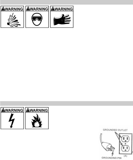
Risk of electric shock or fire.
8.1This battery charger is for use on a nominal 120-volt circuit and has a grounded plug that looks like the plug illustrated. The charger must be grounded to reduce the risk of electric shock. The plug must be plugged into an outlet that is properly installed and grounded in accordance with all local codes and ordinances. The plug pins must fit the receptacle (outlet). Do not use with an ungrounded system.
8.2Never alter the A.C. cord or plug provided – if it does not fit the outlet, have a proper grounded outlet installed by a qualified electrician. An improper connection can result in a risk of an electric shock or electrocution.
•5 •

NOTE: Pursuant to Canadian Regulations, use of an adapter plug is not allowed in Canada. Use of an adapter plug in the United States is not recommended.
8.3Recommended minimum AWG size for extension cord:
A.C. input rating, |
|
AWG size of cord |
|
||
amperes* |
|
Length of cord, feet (m) |
|
||
At |
But less |
25 |
50 |
100 |
150 |
least |
than |
(7.6) |
(15.2) |
(30.5) |
(45.6) |
0 |
2 |
18 |
18 |
18 |
16 |
2 |
3 |
18 |
18 |
16 |
14 |
3 |
4 |
18 |
18 |
16 |
14 |
4 |
5 |
18 |
18 |
14 |
12 |
5 |
6 |
18 |
16 |
14 |
12 |
6 |
8 |
18 |
16 |
12 |
10 |
8 |
10 |
18 |
14 |
12 |
10 |
10 |
12 |
16 |
14 |
10 |
8 |
12 |
14 |
16 |
12 |
10 |
8 |
14 |
16 |
16 |
12 |
10 |
8 |
16 |
18 |
14 |
12 |
8 |
8 |
18 |
20 |
14 |
12 |
8 |
6 |
*If the input rating of a charger is given in watts rather than in amperes, the corresponding ampere rating is to be determined by dividing the wattage rating by the voltage rating - for example:
1200 watts/120 volts = 10 amperes
9.ASSEMBLY INSTRUCTIONS
9.1It is important to fully assemble your charger before use. Follow these instructions for assembly.
|
PARTS |
TOOLS NEEDED |
(2) |
10-32, thread cutting screws |
3/8” wrench (for mounting foot) |
(4) |
¼-20, thread cutting screws |
5/16” wrench (for mounting wheels) |
(4) |
Philips head sheet metal screws |
hammer |
(2) wheels |
screwdriver (flat blade) |
|
(1) axle |
screwdriver (Phillips) |
|
(2) axle caps |
|
|
(2) axle brackets |
|
|
(1) handle |
|
|
(1) foot |
|
|
(1) plastic handle grip (not supplied |
|
|
with all units) |
|
|
• 6 •
9.2Attach the Foot: Remove the charger from the packing materials and place it upside down on a flat surface. Attach the foot and secure it with the four ¼-20 thread cutting screws provided.
9.3Assemble the Wheels and Axle: Hold the axle upright on the floor or work surface. Then, using a hammer, tap one of the axle caps onto the top end of the axle. Be sure to tap the axle cap on straight. Slide both wheels onto the axle with the recessed hubs facing out as shown. Install the second axle cap.
• 7 •
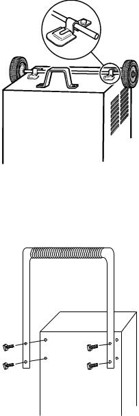
9.4Mount the Axle to the Charger: Place one end of each bracket into the slot on the bottom of the charger. Place the axle assembly under each bracket. Attach the brackets using the two, 10-32 thread cutting screws provided. NOTE: Be careful not to drop the brackets inside of the charger case.
9.5Attach the Handle: If the charger came with a plastic grip, slide that onto the handle until it is centered at the top. Turn the charger right side up onto its foot and wheels. Align the handle so the screw holes are aligned with the screw holes on the upper back corners of the charger. Attach the handle using the four Phillips head screws provided.
• 8 •

10.CONTROL PANEL
Note: Not all controls are available on all models.
Charge Rate Selector Switch
Use the Charge Rate selector switch to select the charge rate or engine starting setting you require.
•2A Slow Charge Rate – Intended for charging small batteries such as those commonly used in garden tractors, snow mobiles and motorcycles.
•10A, 15A, 20A, 30A Fast and 35A, 40A, 44A, 50A, 60A, 80A Rapid Charge Rate – Use for charging automotive, marine and deep-cycle batteries. Not intended for industrial applications.
•100A, 125A, 180A, 200A, 225A, 300A Engine Start – Provides 100, 125, 180, 200, 225 or 300 amps for cranking an engine with a weak or run down battery. Always use in combination with a battery.
Timer (Not applicable for model SE-2352)
•Timer Setting: The timer allows you to set a specified time for charging.
After the timer expires, the charger stops charging your battery. The main function of the timer is to prevent over charging while allowing a battery time to obtain a satisfactory charge. To properly set the timer, you must know the size of the battery in ampere hours or reserve capacity in minutes and the state of charge. It is important that you determine the appropriate state of charge of your battery as specified in Section 12 and set the timer accordingly.
•Hold: This position defeats the timer function, allowing for continuous operation. Be sure to monitor the charging progress and stop it when the battery is charged. Not doing so may cause damage to your battery or may cause other personal property damage or personal injury.
Ammeter
The Ammeter indicates the amount of current, measured in amps, that is being drawn by the battery. As a battery takes on a charge, it draws less current from the charger. Correspondingly, the meter will show less current being drawn by the battery. When the current stops decreasing, the battery is charged. The start area of the meter indicates a high rate of current being drawn from the charger. When cranking an engine, the meter needle will be at the extreme right side of the start area. The 2 amp charge rate may indicate some activity on the meter, although the meter does not have the resolution to display this low rate.
•Percent of Charge
The percent of charge scale is intended as a visual aid to help simplify reading the state of charge. The percent of charge is based on the current drawn by the battery. For this reason, accuracy will vary with the size and battery type. This means that the indication for a fully charged large battery may be slightly less than 100%.
Model SE-2352 employs 2 toggle switches:
•Switch #1 - Use this switch to select the 200 Amp Engine Start and the 35 Amp Charge Rate. Switch #2 must be in the down position (Select Position) when using Switch #1.
•Switch #2 - Use this switch to select the 2 amp Charge Rate and the OFF position. Also, use to select use of Switch #1. Note that Switch #1 is only effective when Switch #2 is set to “Select Position.”
Battery Load Tester Switch (Model SE-8050 only)
When testing a battery, use this switch to apply a load to it.
• 9 •
 Loading...