


Model / Modelo / Modèle:
PSW-70300A
Automatic Battery Charger Cargador de batería automático Chargeur de batterie automatique
Voltage / Tensión / Tension: 12
Amperage / Amperaje / Ampérage:
4, 20, 40, 70
OWNER’S MANUAL Manual del usuario GUIDE D’UTILISATION
DO NOT RETURN THIS PRODUCT TO THE STORE!
Call Customer Service for assistance: 800-621-5485
¡NO LO DEVUELVA este producto A LA TIENDA!
Llame a Servicios al Cliente para asistencia: 800-621-5485
NE PAS RETOURNER LE PRODUIT AU MAGASIN !
Appeler le service clientèle pour l’assistance : 800-621-5485
READ THE ENTIRE MANUAL BEFORE USING THIS PRODUCT. FAILURE TO DO SO COULD RESULT IN SERIOUS INJURY OR DEATH.
LEA EL MANUAL COMPLETO ANTES DE UTILIZAR ESTE PRODUCTO.


 CUALQUIER FALLA PODRÍA RESULTAR EN SERIAS LESIONES O PODRÍA SER MORTAL.
LIRE ENTIÈREMENT LE GUIDE AVANT D’UTILISER CE PRODUIT. L’ÉCHEC 


 DE FAIRE AINSI PEUT S’ENSUIVRE DANS LA BLESSURE SÉRIEUSE OU
LA MORT.
0099001272-00
IMPORTANT: READ AND SAVE THIS SAFETY AND INSTRUCTION MANUAL.
SAVE THESE INSTRUCTIONS – This manual will show you how to use your charger safely and effectively. Please read, understand and follow these instructions and precautions carefully, as this manual contains important safety and operating
instructions. The safety messages used throughout this manual contain a signal word, a message and an icon.
The signal word indicates the level of the hazard in a situation.
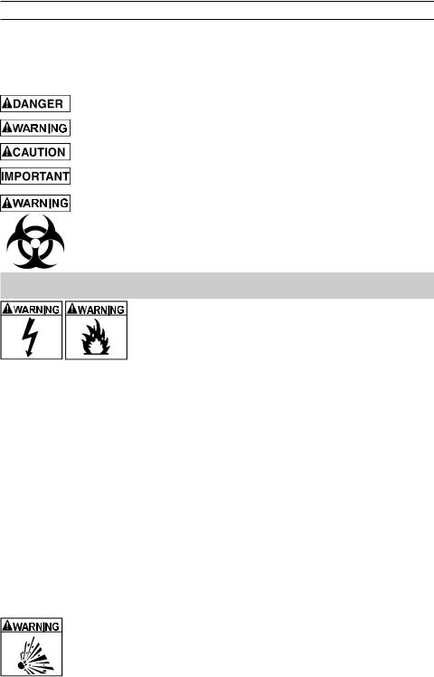
Indicates an imminently hazardous situation which, if not avoided, will result in death or serious injury to the operator or bystanders.
Indicates a potentially hazardous situation which, if not avoided, could result in death or serious injury to the operator or bystanders.
Indicates a potentially hazardous situation which, if not avoided, could result in moderate or minor injury to the operator or bystanders.
Indicates a potentially hazardous situation which, if not avoided, could result in damage to the equipment or vehicle or property damage.
Pursuant to California Proposition 65, this product contains chemicals known to the State of California to cause cancer and birth defects or other reproductive harm. Wash hands after handling.
1.IMPORTANT SAFETY INSTRUCTIONS – SAVE THESE INSTRUCTIONS.
This manual contains important safety and operating instructions.
RISK OF ELECTRIC SHOCK OR FIRE.
1.1Keep out of reach of children.
1.2Do not expose the charger to rain or snow.
1.3Use only recommended attachments. Use of an attachment not recommended or sold by Schumacher® Electric Corporation
may result in a risk of fire, electric shock or injury to persons or damage to property.
1.4To reduce the risk of damage to the electric plug or cord, pull by the plug rather than the cord when disconnecting the charger.
1.5An extension cord should not be used unless absolutely necessary. Use of an improper extension cord could result in a risk of fire and electric shock. If an extension cord must be used, make sure:
•That the pins on the plug of the extension cord are the same number, size and shape as those of the plug on the charger.
•That the extension cord is properly wired and in good electrical condition.
•That the wire size is large enough for the AC ampere rating of the charger as specified in section 8.
1.6To reduce the risk of electric shock, unplug the charger from the outlet before attempting any maintenance or cleaning. Simply turning off the controls will not reduce this risk.
1.7Do not operate the charger with a damaged cord or plug; have the cord or plug replaced immediately by a qualified service person. (Call customer service at 1-800-621-5485.)
1.8Do not operate the charger if it has received a sharp blow, been dropped or otherwise damaged in any way; take it to a qualified service person. (Call customer service at 1-800-621-5485.)
1.9Do not disassemble the charger; take it to a qualified service person when service or repair is required. Incorrect reassembly may result in a risk of fire or electric shock. (Call customer service at 1-800-621-5485.)
RISK OF EXPLOSIVE GASES.
1.10 WORKING IN THE VICINITY OF A LEAD-ACID BATTERY IS DANGEROUS. BATTERIES GENERATE EXPLOSIVE GASES DURING NORMAL BATTERY OPERATION. FOR THIS REASON, IT IS OF UTMOST IMPORTANCE THAT YOU FOLLOW THE INSTRUCTIONS EACH TIME YOU USE THE CHARGER.
• 2 •
1.11To reduce the risk of a battery explosion, follow these instructions and those published by the battery manufacturer and the manufacturer of any equipment you intend to use in the vicinity of the battery. Review the cautionary markings on these products and on the engine.
1.12This charger employs parts, such as switches and circuit breakers, that tend to produce arcs and sparks. If used in a garage, locate this charger 18 inches (46 cm) or more above floor level.
2.PERSONAL PRECAUTIONS
RISK OF EXPLOSIVE GASES.
2.1NEVER smoke or allow a spark or flame in the vicinity of a battery or engine.
2.2Remove personal metal items such as rings, bracelets, necklaces and watches when working with a lead-acid battery. A lead-acid battery can produce a short-circuit current high enough to weld a ring or the like to metal, causing a severe burn.
2.3Be extra cautious, to reduce the risk of dropping a metal tool onto the battery. It might spark or short-circuit the battery or other electrical part that may cause an explosion.
2.4Use this charger for charging LEAD-ACID batteries only. It is not intended to supply power to a low voltage electrical system other than in a starter-motor application. Do not use this battery charger for charging dry-cell batteries that are commonly used with home
appliances. These batteries may burst and cause injury to persons and damage to property.
2.5NEVER charge a frozen battery.
2.6NEVER overcharge a battery.
2.7Consider having someone nearby to come to your aid when you work near a lead-acid battery.
2.8Have plenty of fresh water and soap nearby in case battery acid contacts your skin, clothing or eyes.
2.9Wear complete eye and body protection, including safety goggles and protective clothing. Avoid touching your eyes while working near the battery.
2.10If battery acid contacts your skin or clothing, immediately wash the area with soap and water. If acid enters your eye, immediately flood the eye with cold running water for at least 10 minutes and get medical attention right away.
2.11If battery acid is accidentally swallowed, drink milk, the whites of eggs or water. DO NOT induce vomiting. Seek medical attention immediately.
3.PREPARING TO CHARGE
RISK OF CONTACT WITH BATTERY ACID. BATTERY ACID IS A
HIGHLY CORROSIVE SULFURIC ACID.
3.1If it is necessary to remove the battery from the vehicle to charge it, always remove the grounded terminal first. Make sure all of the accessories in the vehicle are off to prevent arcing.
3.2Be sure the area around the battery is well ventilated while the battery is being charged.
3.3Clean the battery terminals before charging the battery. During cleaning, keep airborne corrosion from coming into contact with your eyes, nose and mouth. Use baking soda and water to neutralize the battery acid and help eliminate airborne corrosion. Do not touch your eyes, nose or mouth.
3.4Add distilled water to each cell until the battery acid reaches the level specified by the battery manufacturer. Do not overfill. For a battery without removable cell caps, such as valve regulated lead acid batteries (VRLA), carefully follow the manufacturer’s recharging instructions.
3.5Read, understand and follow all instructions for the charger, battery, vehicle and any equipment used near the battery and charger. Study all of the battery manufacturer’s specific precautions while charging and recommended rates of charge.
3.6Determine the voltage of the battery by referring to the vehicle owner’s manual and make sure that the output voltage selector switch is set to the correct voltage. If the charger has an adjustable charge rate, charge the battery in the lowest rate first.
3.7Make sure that the charger cable clips make tight connections.
•3 •

4.CHARGER LOCATION
RISK OF EXPLOSION AND CONTACT WITH
BATTERY ACID.
4.1Locate the charger as far away from the battery as the DC cables permit.
4.2Never place the charger directly above the
battery being charged; gases from the battery will corrode and damage the charger.
4.3Do not set the battery on top of the charger.
4.4Never allow battery acid to drip onto the charger when reading the electrolyte specific gravity or filling the battery.
4.5Do not operate the charger in a closed-in area or restrict the ventilation in any way.
5.DC CONNECTION PRECAUTIONS
5.1Connect and disconnect the DC output clips only after setting all of the charger switches to the “off” position (if applicable) and removing the AC plug from the electrical outlet.
Never allow the clips to touch each other.
5.2Attach the clips to the battery and chassis, as indicated in sections 6 and 7.
6.FOLLOW THESE STEPS WHEN BATTERY IS INSTALLED IN VEHICLE
A SPARK NEAR THE BATTERY MAY CAUSE A
BATTERY EXPLOSION. TO REDUCE THE RISK OF A SPARK NEAR THE BATTERY:
6.1 Position the AC and DC cables to reduce the risk of damage by the hood, door and moving or hot engine parts. NOTE: If it is necessary to close the
hood during the charging process, ensure that the hood does not touch the metal part of the battery clips or cut the insulation of the cables.
6.2Stay clear of fan blades, belts, pulleys and other parts that can cause injury.
6.3Check the polarity of the battery posts. The POSITIVE (POS, P, +) battery post usually has a larger diameter than the NEGATIVE (NEG, N, -) post.
6.4Determine which post of the battery is grounded (connected) to the chassis. If the negative post is grounded to the chassis (as in most vehicles), see step 6.5. If the positive post is grounded to the chassis, see step 6.6.
6.5For a negative-grounded vehicle, connect the POSITIVE (RED) clip from the battery charger to the POSITIVE (POS, P, +) ungrounded post of the battery. Connect the NEGATIVE (BLACK) clip to the vehicle chassis or engine block away from the battery.
Do not connect the clip to the carburetor, fuel lines or sheet-metal body parts. Connect to a heavy gauge metal part of the frame or engine block.
6.6For a positive-grounded vehicle, connect the NEGATIVE (BLACK) clip from the battery charger to the NEGATIVE (NEG, N, -) ungrounded post of the battery. Connect the POSITIVE (RED) clip to the vehicle chassis or engine block away from the battery. Do not connect the clip to the carburetor, fuel lines or sheet-metal body parts. Connect to a heavy gauge metal part of the frame or engine block.
6.7Connect charger AC supply cord to electrical outlet.
6.8When disconnecting the charger, turn all switches to off, disconnect the AC cord, remove the clip from the vehicle chassis and then remove the clip from the battery terminal.
6.9See CALCULATING CHARGE TIME for length of charge information.
7.FOLLOW THESE STEPS WHEN BATTERY IS OUTSIDE VEHICLE
A SPARK NEAR THE BATTERY MAY CAUSE A BATTERY EXPLOSION. TO REDUCE THE RISK OF A SPARK NEAR THE BATTERY:
7.1 Check the polarity of the battery posts. The
POSITIVE (POS, P, +) battery post usually has a larger diameter than the NEGATIVE (NEG, N, -) post.
7.2Attach at least a 24-inch (61 cm) long 6-gauge (AWG) insulated battery cable to the NEGATIVE (NEG, N, -) battery post.
7.3Connect the POSITIVE (RED) charger clip to the POSITIVE (POS, P, +) post of the battery.
•4 •
7.4Position yourself and the free end of the cable you previously attached to the NEGATIVE
(NEG, N, -) battery post as far away from the battery as possible – then connect the NEGATIVE (BLACK) charger clip to the free end of the cable.
7.5Do not face the battery when making the final connection. As stated in 7.4, face away from the battery when connecting the negative clip to the cable.
7.6Connect charger AC supply cord to electrical outlet.
7.7When disconnecting the charger, always do so in the reverse order of the connecting procedure and break the first connection while as far away from the battery as practical.
7.8A marine (boat) battery must be removed and charged on shore. To charge it onboard requires equipment specially designed for marine use.
8.grounding and ac power cord connections
 RISK OF ELECTRIC SHOCK OR FIRE.
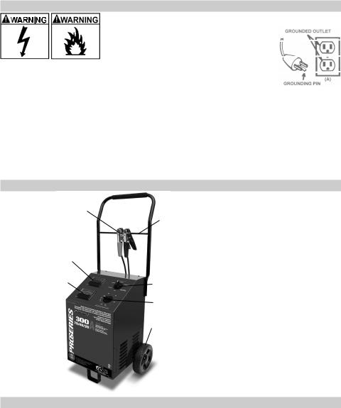
8.1 This battery charger is for use on a nominal 120-volt circuit and has a grounded plug that looks like the plug illustrated. The charger must be grounded to reduce the risk of electric shock. The plug must be plugged into
an outlet that is properly installed and grounded in accordance with all local codes and ordinances. The plug pins must fit the receptacle (outlet). Do not use with an ungrounded system.
8.2 Never alter the AC cord or plug provided – if it does not fit the outlet, have a proper grounded outlet installed by a qualified electrician. An improper connection can result in a risk of an electric shock or electrocution. NOTE: Pursuant to Canadian Regulations, use of an adapter plug is not allowed in Canada. Use of an adapter plug in the United States is not recommended and should not be used.
8.3Recommended minimum AWG size for extension cord:
•100 feet (30.5 meters) long or less - use an 10 gauge (5.26 mm2) extension cord.
•Over 100 feet (30.5 meters) long - use a 8 gauge (8.36 mm2) extension cord.
9.FEATURES
 3
3
5
4
|
|
1. |
Ammeter |
|
2 |
|
2. |
Voltmeter |
|
|
|
3. |
Foam Grip |
|
1 |
6 |
4. |
Fiberglass Clip Rod |
|
5. |
Battery Clips |
|||
|
||||
|
|
|||
|
7 |
6. |
Charge Rate Selector Switch |
|
|
7. |
Timer |
||
|
|
|||
|
8 |
8. |
Wheel |
|
|
|
|
10.ASSEMBLY INSTRUCTIONS
It is important to fully assemble your charger before use. Follow these instructions for assembly.
•5 •
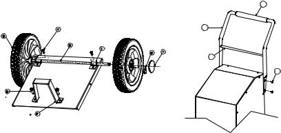
Item |
|
PARTS |
TOOLS NEEDED |
1 |
(2) axle brackets |
3/8" wrench (for mounting foot) |
|
2 |
(1) axle with pin holes |
5/16" wrench (for mounting wheels) |
|
3 |
(2) wheels |
1/4" wrench (for mounting handle) |
|
4 |
(2) |
10-32, thread cutting screws |
hammer |
5 |
(2) |
¼-20, thread cutting screws |
screwdriver (flat blade) |
6 |
(1) foot |
screwdriver (Phillips) |
|
7 |
(2) axle caps |
|
|
8 |
(2) hairpin cotter |
|
|
9 |
(4) |
8-18 sheet metal screws |
|
10 |
(1) handle |
|
|
11 |
(1) fiberglass clamp rod |
|
|
12 |
(1) foam handle grip |
|
|
1.Carefully lay the charger on its front to prepare for assembly.
2.Assemble the foot (Item 6) using two ¼-20 screws (Item 5) and tighten securely.
3.Attach the two axle brackets (Item 1) using one 10-32 screw (Item 4) in each. The brackets should have one end hooked into the slot in the charger base. Be careful not to drop the brackets inside of the charger case. Do not completely tighten the screws (Item 4) at this time.
4.Slide the axle (Item 2) into the brackets (Item 1) until centered on the charger.
5.Slide one wheel (Item 3) onto the axle with the recessed hub facing out as shown.
6.Insert the pin (Item 8) through the axle hole.
7.Repeat this process for the other wheel and when both wheels have been pinned to the axle, finish tightening the two axle bracket screws (Item 4).
8.Snap the axle caps (Item 7) onto each wheel to cover the pin and axle.
9.Lift the charger upright so that it rests on the wheels and foot.
10.Remove the two top side screws (Item 9) from each side of the charger.
11.Verify that the foam handle grip (Item 12) is on the handle assembly (Item 10). Install if needed.
12.Insert the fiberglass clamp rod (Item 11) into the pierced holes on the inside of the handle (Item 10).
13.Align the handle assembly (Item 10) with charger and reinstall the side screws (Item 9). Do not over tighten.
14.The charger assembly is now complete. The battery clips can be clamped to the fiberglass rod (Item 11) for convenient storage.
15.Do not attach the clips to the foam area of the handle; this will damage the foam grip.
12
10
11
9
• 6 •

11.CONTROL PANEL Timer
•Timer Setting: The timer allows you to set a specified time for charging. After the timer expires, the charger stops charging your battery. The main function of the timer is to prevent over charging while allowing a battery time to obtain a satisfactory charge. To properly set the timer, you must know the size of the battery in ampere hours or reserve capacity in minutes and the state of charge. It is important that you determine the appropriate state of charge of your battery as specified in Section 13 and set the timer accordingly.
•Hold: This position defeats the timer function, allowing for continuous operation.
•Automatic Modes: Put the timer in the HOLD position when using the battery charger in one of the Automatic Modes (4, 20 or 70 amp), otherwise the timer will stop the charging process when the time expires regardless of whether
it is complete or not. The CHARGED (green) LED will light when charging is complete and the charger goes into Maintain Mode. The charger will not shut off.
•Manual Modes: Put the timer in the HOLD position when using the battery charger in the Manual Mode (40 amp) and when you want to charge more than 2¼ hours. Be sure to monitor the charging progress and stop it when the battery is charged. Not doing so may cause damage to your battery or may cause other personal property damage or personal injury.
Ammeter
The Ammeter indicates the amount of current, measured in amps, that is being drawn by the battery. As a battery takes on a charge, it draws less current from the charger. Correspondingly, the meter will show less current being drawn by the battery. When the current stops decreasing, the battery is charged. The 4 amp charge rate may indicate some activity on the meter, although the meter does not have the resolution to display this low rate.
Voltmeter
The voltmeter indicates the voltage at the battery terminals. The charger need not be plugged into an AC outlet. The timer should be in the OFF position. Then connect the charger following the instructions in Sections 6 and 7. Observe the meter indication.
Keep in mind that this reading is only a battery voltage reading, a false surface charge may mislead you. We suggest that you turn on the headlights for a couple of minutes before you read the meter. Read it a couple of minutes after you have shut the headlights off. If the reading is less than 10.5-volts, the battery may be bad or the connection at the charger may be poor. If the reading is 10.5-volts to 12.8-volts, the battery is low – recharge it. If the reading is above 12.8-volts, the battery is charged.
Charge Rate Selector Switch
Use the Charge Rate selector switch to select the charge rate or engine starting setting you require.
•4A Slow Charge Rate – Intended for charging small batteries such as those commonly used in garden tractors, snow mobiles and motorcycles.
•20A and 40A Fast and 70A Rapid Charge Rate – Use for charging automotive, marine and deep-cycle batteries. Not intended for industrial applications.
•300A Engine Start – Provides 300 amps for cranking an engine with a weak or run down battery. Always use in combination with a battery.
12.OPERATING INSTRUCTIONS
Automatic Temperature Compensation
The charger adjusts the maximum charge voltage and maximum maintain voltage based on the ambient air temperature. This permits optimum charging and safety.
Thermal Runaway
The charger automatically reduces the current if it detects the battery may be getting too hot. This is a safety precaution.
Charging
1.Ensure that all of the charger components are in place and in good working condition, including the plastic boots on the battery clips. Make sure the electrolyte
(battery liquid) in each cell is at the correct level.
2.Set the charge rate switch and the timer to the OFF position.
•7 •
3.Connect the battery following the precautions listed in Sections 6 and 7.
4.Connect the AC power following the precautions listed in Section 8.
5.Select the desired charge rate. NOTE: The 40 amp Manual rate is a manual mode and will overcharge a battery if permitted to operate for extended periods of time. Monitor the charging process often.
6.Turn the timer to HOLD or the selected charge time if using the 40 amp Manual Mode.
7.To disconnect the charger, reverse the procedure.
NOTE: This charger is equipped with a safe start feature. In the Automatic 4, 20 and 70 amp charge rates it will not supply current to the battery clips until a battery is properly connected. Unlike traditional chargers, the clips will not spark if touched together. In the Manual 40 amp charge rate, the clips will spark if accidently touched together.
Automatic Charging Mode
When an Automatic Charge is performed, the charger switches to the Maintain Mode
(see below) automatically after the battery is charged. For a battery with a starting voltage under 1 volt, use the Manual Mode (see Manual Charging section) first to pre-charge the battery for five minutes to get additional voltage into the battery for the charger to analyze.
Manual Charging Mode
When you select the 40 Amp Manual Mode charge rate, you will be charging in manual mode. You must set the timer to the proper time (see Timer section). Be sure to monitor the charging procedure and stop it when the battery is charged. Not doing so may cause damage to your battery or result in other property damage or personal injury.
Aborted Charge
If charging can not be completed normally, charging will abort. When charging aborts, the charger’s output is shut off. To reset after an aborted charge, either disconnect the battery or unplug the charger.
Desulfation Mode
If the battery is left discharged for an extended period of time, it could become sulfated and not accept a normal charge. If the charger detects a sulfated battery, the charger will switch to a special mode of operation designed for such batteries. If successful, normal charging will resume after the battery is desulfated. Desulfation could take 8 to
10 hours. If desulfation fails, charging will abort (see Aborted Charge section).
Completion of Charge
Charge completion is indicated by the CHARGED (green) LED. When lit, the charger has switched to the Maintain Mode of operation.
Maintain Mode (Float-Mode Monitoring)
When the CHARGED (green) LED is lit, the charger has started Maintain Mode. In this mode, the charger keeps the battery fully charged by delivering a small current when necessary. If the battery voltage drops below a preset level, the charger will go back into Charge Mode until the battery voltage returns to the full charge level, at which point the charger will return to Maintain Mode.
NOTE: The charger automatically switches between Charge Mode and Maintain Mode as necessary. The CHARGED (green) LED will cycle on when the battery is at full charge and off when the voltage drops below a preset level and the charger goes into
Charge Mode. This cycle will continue, and the CHARGED (green) LED will stay on for longer periods of time as the battery becomes more fully charged.
Using the Engine Start feature
Your battery charger can be used to jumpstart your car if the battery is low. Follow these instructions on how to use the ENGINE START feature.
 Follow all safety instructions and precautions for charging your battery. Wear complete eye protection and clothing protection. Charge your battery in a wellventilated area.
 Using the ENGINE START feature WITHOUT a battery installed in the vehicle could cause damage to the vehicle’s electrical system. NOTE: If you have charged the battery and it still will not start your car, do not use the engine start feature, or it could damage the vehicle’s electrical system.
• 8 •
1.Set the charge rate switch and the timer to the OFF position.
2.With the charger unplugged from the AC outlet, connect the charger to the battery following the instructions given in Section 6 (FOLLOW THESE STEPS WHEN THE BATTERY IS INSTALLED IN A VEHICLE).
3.Plug the charger AC power cord into the AC outlet, and then move the timer switch from OFF to the HOLD position.
4.With the charger plugged in and connected to the battery of the vehicle, set the charge rate selector switch to the engine start position.
5.Crank the engine until it starts or 3 seconds pass. If the engine does not start, wait 3 minutes before cranking again. This allows the charger and battery to cool down.
NOTE: During extremely cold weather, or if the battery is under 2 volts, charge the battery for 5 minutes before cranking the engine.
6.If the engine fails to start, charge the battery for 5 more minutes before attempting to crank the engine again.
7.After the engine starts, move the charge rate selector switch to the OFF position and unplug the AC power cord before disconnecting the battery clips from the vehicle.
8.Clean and store the charger in a dry location.
NOTE: If the engine does turn over but never starts, there is not a problem with the starting system; there is a problem somewhere else with the vehicle. STOP cranking the engine until the other problem has been diagnosed and corrected.
Using the Battery Voltage Tester
Overview
This battery charger has a built-in voltmeter to test your battery’s state of charge. The charger does not have a built in load tester. As such, a recently charged battery could have a temporarily high voltage due to what is known as “surface charge”. The voltage of such a battery will gradually drop during the period immediately after the charging system is disengaged. Consequently, the tester could display inconsistent values for such a battery. For a more accurate reading, the surface charge should be removed by temporarily creating a load on the battery, such as by turning on lights or other accessories for a couple of minutes before you read the display. Read it a couple of minutes after you have shut the headlights off.
Testing Sequence: There are four basic steps required to test the battery state of charge:
1.With the charger unplugged from the AC outlet, connect the charger to the battery following the instructions given in Sections 6 and 7.
2.Set the charge rate switch and the timer to the OFF position.
3.Plug the charger AC power cord into the AC outlet, following the instructions given in Section 8.
4.Read the voltage on the voltmeter.
Using the Alternator Performance Tester
Overview
This battery charger has a built-in alternator tester that displays an estimate of the alternator’s relative output compared to normal alternators. The alternator % values displayed should be taken as a general reference, not a precise diagnosis. The alternator tester functions the same as the built-in battery voltage tester (see previous section for details) with a few differences.
Testing Sequence: There are four basic steps required to operate this unit as an alternator tester:
1.With the charger unplugged from the AC outlet, connect the charger to the battery following the instructions given in Sections 6 and 7.
2.Set the charge rate switch and the timer to the OFF position.
3.Plug the charger AC power cord into the AC outlet, following the instructions given in Section 8.
4.Start the vehicle and turn on the vehicle’s headlights. Read the voltage on the voltmeter.
•9 •

General Charging Notes
Fan: The charger is designed to control its cooling fan for efficient operation.
Consequentially, it is normal for the fan to start and stop when maintaining a fully charged battery. Keep the area near the charger clear of obstructions to allow the fan to operate efficiently.
Voltage: The voltage displayed during charging is the charging voltage and is usually higher than the battery’s resting voltage.
13. CALCULATING CHARGE TIME
The Hydrometer or Electronic Method
To find the time needed to fully charge your battery, determine the battery’s charge level with a hydrometer or electronic Percent-of-Charge Tester. The following table will help you convert hydrometer readings to percent of charge values.
SPECIFIC GRAVITY |
PERCENT OF CHARGE |
PERCENT OF CHARGE |
|
NEEDED |
|||
|
|
||
1.265 |
100% |
0% |
|
1.225 |
75% |
25% |
|
1.155 |
25% |
75% |
|
1.120 |
0% |
100% |
When you know the percent of charge and the Amp Hour (AH) rating of your battery, you can calculate the approximate time needed to bring your battery to a full charge.
To convert Reserve Capacity to Amp Hours, divide Reserve Capacity by 2, and add 16:
Example:
Amp Hour Rating = Reserve Capacity + 16 2
NOTE: The Reserve Capacity can be obtained from the battery specification sheet or the owner’s manual.
To calculate the time needed for a charge:
1.Find the percent of charge needed. (A battery at 50 percent charge that will be charged to 100 percent needs another 50 percent (.50)).
2.Multiply the Amp Hour Rating by the charge needed (.50) and divide by the charge rate.
3.Multiply the results by 1.25 and you will have the total time needed, in hours, to bring the battery to full charge.
4.Add an additional hour for a deep-cycle battery.
Example:
Amp Hour Rating x % of charge needed x 1.25 = hours of charge Charger Setting
100 (AH Rating) x .50 (charge needed) x 1.25 = 3.125 hours 20 (Charger Setting)
100 x .50 x 1.25 = 3.125
20
You would need to charge your 100-Ampere Hour Battery for a little more than 3 hours at the 20-Amp charge rate using the above example.
• 10 •
The Chart Method
Use the following table to more accurately determine the time it will take to bring a battery to full charge. First, identify where your battery fits into the chart.
NR means that the charger setting is NOT RECOMMENDED.
Find your battery’s rating on the chart below, and note the charge time given for each charger setting. The times given are for batteries with a 50% charge prior to recharging. Add more time for severely discharged batteries.
BATTERY SIZE/RATING |
CHARGE RATE/CHARGING TIME |
||||||
4 AMP |
20 AMP |
40 AMP |
70 Amp |
||||
|
|
|
|||||
SMALL |
Motorcycle, |
6 - 12 AH |
1 - 2 hrs |
NR |
NR |
NR |
|
garden, |
|
|
|
|
|
||
BATTERIES |
12 - 32 AH |
2 - 5 hrs |
NR |
NR |
NR |
||
tractor, etc. |
|||||||
|
200 - 315 CCA |
40 - 60 RC |
5½ - 7¼ |
1 - 1½ |
½ - ¾ hr |
20 - 30 |
|
|
|
|
hrs |
hrs |
|
min |
|
CARS/ |
315 - 550 CCA |
60 - 85 RC |
7¼ - 9¼ |
1½ - 2 |
¾ - 1 hr |
30 - 40 |
|
TRUCKS |
|
|
hrs |
hrs |
|
min |
|
|
550 - 1000 CCA |
80 - 190 RC |
9¼ - |
2 - 3½ |
1 - 1¾ |
40 min - |
|
|
17½ hrs |
hrs |
hrs |
1 hr |
|||
|
|
|
|||||
|
|
80 RC |
8¾ hrs |
1¾ hrs |
NR |
NR |
|
MARINE/DEEP CYCLE |
140 RC |
13½ hrs |
2¾ hrs |
NR |
NR |
||
160 RC |
15 hrs |
3 hrs |
NR |
NR |
|||
|
|
||||||
|
|
180 RC |
16½ hrs |
3½ hrs |
NR |
NR |
|
14.MAINTENANCE INSTRUCTIONS
14.1After use and before performing maintenance, unplug and disconnect the battery charger (see Sections 6, 7 and 8).
14.2Use a dry cloth to wipe all battery corrosion and other dirt or oil from the terminals, cords, and the charger case.
14.3Ensure that all of the charger components are in place and in good working condition, including the plastic boots on the battery clips.
14.4Servicing does not require opening the unit, as there are no user-serviceable parts.
14.5All other servicing should be performed by qualified service personnel.
15.MOVING AND STORAGE INSTRUCTIONS
15.1Store the charger unplugged, in an upright position. The cord will still conduct electricity until it is unplugged from the outlet.
15.2Store inside, in a cool, dry place.
15.3Store the clips on the fiberglass clamp rod. Do not store them on the handle, clipped together, on or around metal, or clipped to the cables.
15.4if the charger is moved around the shop or transported to another location, take care to avoid/prevent damage to the cords, clips and charger. Failure to do so could result in personal injury or property damage.
• 11 •

16.TROUBLESHOOTING
PROBLEM |
POSSIBLE CAUSE |
REASON/SOLUTION |
No reading on the |
Charger is not plugged in. |
Plug the charger into an AC outlet. |
ammeter. |
No power at the receptacle. |
Check for open fuse or circuit |
|
||
|
|
breaker supplying AC outlet. |
|
Clips are not making a good |
Check for poor connection to |
|
connection to the battery. |
battery and frame. Make sure |
|
|
connection points are clean. |
|
|
Rock clips back and forth for a |
|
|
better connection. |
|
Connections are reversed. |
Unplug the charger and reverse |
|
|
the clips. |
|
Battery is defective (will not |
Have battery checked. |
|
accept a charge). |
|
|
4 amp charge rate is being used. |
Ammeter may show no activity at |
|
|
the 4A charge rate. |
Ammeter reading |
Battery is severely discharged. |
Continue charging battery for two |
stays high. |
|
more hours. If problem continues |
|
|
have the battery checked. |
|
Wrong battery voltage. |
Verify the voltage settings on the |
|
|
charger are correct. |
Ammeter reads less than |
Extension cord is too long or wire |
Use a shorter or heavier gauge |
selected charge rate when |
gauge is too small. |
extension cord. |
charging a discharged |
Weak cell or sulfated plate in |
A sulfated battery will eventually |
battery |
||
|
battery. |
take a normal charge if left |
|
|
connected. If the battery will not |
|
|
take a charge, have it checked. |
|
Battery is only partially |
Continue to charge the battery. |
|
discharged. |
|
Battery clips do not spark |
The charger is equipped with |
No problem; this is a normal |
when touched together. |
a safe start feature. In the |
condition. |
|
automatic modes, it will not |
|
|
supply current to the battery |
|
|
clips until a battery is properly |
|
|
connected. Unlike traditional |
|
|
chargers, the clips will no spark if |
|
|
touched together. |
|
The charger is making an |
Circuit breaker is cycling. |
The settings may be wrong. |
audible clicking sound. |
|
Check the charger settings. |
|
Battery is defective. |
Have the battery checked. |
|
Shorted battery cables or clips. |
Circuit breaker cycles when |
|
|
current draw is too high. Check |
|
|
for shorted cables or clips and |
|
|
replace if necessary. |
|
Severely discharged battery, but |
The battery may not want to |
|
otherwise it is a good battery. |
accept a charge due to a run- |
|
|
down state. Allow charging to |
|
|
continue until battery has a |
|
|
chance to recover sufficiently to |
|
|
take a charge. If more than 20 |
|
|
minutes, stop charging and have |
|
|
the battery checked. |
|
Reverse connections at battery. |
Shut the charger off and correct |
|
|
the lead connections. |
• 12 •

PROBLEM |
POSSIBLE CAUSE |
REASON/SOLUTION |
Charger makes a loud buzz |
Transformer laminations vibrate |
No problem; this is a normal |
or hum. |
(buzz). |
condition. |
|
Shorted Diode Assembly or |
Have charger checked by a |
|
Output Rectifier Assembly (hum). |
qualified technician. |
Short or no start cycle |
Drawing more than 300 amps. |
Crank time varies with the |
when cranking engine. |
|
amount of current drawn. If |
|
|
cranking draws more than 300 |
|
|
amps, crank time may be less |
|
|
than 3 seconds. |
|
Failure to wait 3 minutes (180 |
Wait 3 minutes of rest time |
|
seconds) between cranks. |
before the next crank. |
|
Clips are not making a good |
Check for poor connection at |
|
connection. |
battery and frame. |
|
AC cord and/or extension cord |
Check power cord and extension |
|
is loose. |
cord for loose fitting plug. |
|
No power at receptacle. |
Check for open fuse or circuit |
|
|
breaker supplying AC outlet. |
|
The charger may be overheated. |
The thermal protector may have |
|
|
tripped and needs a little longer |
|
|
to reset. Make sure the charger |
|
|
vents are not blocked. Wait and |
|
|
try again. |
|
Battery may be severely |
On a severely discharged battery, |
|
discharged. |
charge for 10 to 15 minutes in |
|
|
the 40 amp manual rate to help |
|
|
assist in cranking. |
Charger will not turn on |
AC outlet is dead. |
Check for open fuse or circuit |
when properly connected. |
|
breaker supplying AC outlet. |
|
Poor electrical connection. |
Check power cord and extension |
|
|
cord for loose fitting plug. |
The battery is connected |
Clips are not making a good |
Check for poor connection at |
and the charger is on, but |
connection. |
battery and frame. Make sure |
is not charging. |
|
connecting points are clean. |
|
|
Rock clips back and forth for a |
|
|
better connection. |
The measured current is |
The charger reached the |
No problem; this is a normal |
much lower than what was |
maximum voltage and is |
condition. |
selected. |
reducing the current. |
|
17.BEFORE RETURNING FOR REPAIRS
17.1When a charging problem arises, make certain that the battery is capable of accepting a normal charge. Use a good battery to double check all connections, the AC outlet for a full 120-volts, the charger clips for correct polarity and the quality of the connections from the cables to the clips and from the clips to the battery system. The clips must be clean.
17.2When a battery is very cold, partially charged or sulfated, it will not draw the full rated amperes from the charger. It is both dangerous and damaging to a battery to force higher amperage into it than it can effectively use in recharging.
17.3When an UNKNOWN OPERATING PROBLEM arises, please read the complete manual and call the customer service number for information. This will usually eliminate the need for return.
If the above solutions do not eliminate the problem or for information about troubleshooting or replacement parts, call toll-free from anywhere in the U.S.A.
1-800-621-5485
7:00 am to 5:00 pm Central Time Monday thru Friday
• 13 •

18.LIMITED WARRANTY
Warranty not valid in Mexico.
SCHUMACHER ELECTRIC CORPORATION, 801 BUSINESS CENTER DRIVE, MOUNT PROSPECT, IL 60056-2179, MAKES THIS LIMITED WARRANTY TO THE ORIGINAL RETAIL PURCHASER OF THIS PRODUCT. THIS LIMITED WARRANTY IS NOT TRANSFERABLE OR ASSIGNABLE.
Schumacher Electric Corporation (the “Manufacturer”) warrants this battery charger for 3 years from the date of purchase at retail against defective material or workmanship that may occur under normal use and care. If your unit is not free from defective material or workmanship, Manufacturer’s obligation under this warranty is solely to repair or replace your product with a new or reconditioned unit at the option of the Manufacturer. It is the obligation of the purchaser to forward the unit, along with proof of purchase and mailing charges prepaid to the Manufacturer or its authorized representatives in order for repair or replacement to occur.
Manufacturer does not provide any warranty for any accessories used with this product that are not manufactured by Schumacher Electric Corporation and approved for use with this product. This Limited Warranty is void if the product is misused, subjected to careless handling, repaired, or modified by anyone other than Manufacturer or if this unit is resold through an unauthorized retailer.
Manufacturer makes no other warranties, including, but not limited to, express, implied or statutory warranties, including without limitation, any implied warranty of merchantability or implied warranty of fitness for a particular purpose. Further,
Manufacturer shall not be liable for any incidental, special or consequential damage claims incurred by purchasers, users or others associated with this product, including, but not limited to, lost profits, revenues, anticipated sales, business opportunities, goodwill, business interruption and any other injury or damage. Any and all such warranties, other than the limited warranty included herein, are hereby expressly disclaimed and excluded. Some states do not allow the exclusion or limitation of incidental or consequential damages or length of implied warranty, so the above limitations or exclusions may not apply to you. This warranty gives you specific legal rights and it is possible you may have other rights which vary from this warranty.
THIS LIMITED WARRANTY IS THE ONLY EXPRESS LIMITED WARRANTY AND THE MANUFACTURER NEITHER ASSUMES OR AUTHORIZES ANYONE TO ASSUME OR MAKE ANY OTHER OBLIGATION TOWARDS THE PRODUCT OTHER THAN THIS WARRANTY.
Schumacher Electric Corporation Customer Service 1-800-621-5485
Monday–Friday 7:00 a.m. to 5:00 p.m. CST
Schumacher® and the Schumacher Logo® are registered trademarks of Schumacher Electric Corporation.
To activate the warranty, please fill in the warranty registration card on page 15 and mail it in,
OR go to www.batterychargers.com to register your product online.
DO NOT RETURN THIS PRODUCT TO THE STORE!
Call Customer Service for assistance: 800-621-5485
• 14 •

3 YEAR LIMITED WARRANTY PROGRAM
REGISTRATION
MODEL:___________________ DESCRIPTION:___________________________
This is the only express limited warranty, and the manufacturer neither assumes nor authorizes anyone to assume or make any other obligation. There is no other warranty, other than what is described in the product owner’s manual.
The warranty card should be submitted within 30 days of purchase. The customer must keep the ORIGINAL receipt because it will be required for any warranty claims. This warranty is not transferable. Send warranty card only.
|
Do not send unit to this address for repair. |
Mail this card to: |
Schumacher Electric Corporation |
|
801 Business Center Drive |
|
Mount Prospect, IL 60056-2179 |
Name_______________________________________________________________
Street Address________________________________________________________
City_________________________________State__________Zip Code__________
Phone______________________Email____________________________________
Store Name Where Purchased____________________Date of Purchase__________
Store Location_____________________UPC Number_________________________
Serial Number________________________(SEE PRODUCT)
PROGRAMA DE REGISTRO DE 3-AÑOS DE GARANTÍA
LIMITADA
MODELO:___________________ DESCRIPCIÓN:___________________________
Esta es la única garantía limitada expresa, y el productor no autoriza ni otorga a alguien a realizar alguna otra obligación. No existe ninguna otra garantía más que la descrita en el manual del dueño.
La tarjeta de garantía debe enviarse durante los primeros 30 días después de la compra. El cliente debe mantener el recibo de compra ORIGINAL como comprobante,
el cual le otorga todo derecho a cualquier reclamo de garantía. Esta garantía no es transferible. Envie tarjeta de garantía solamente.
No envíe la unidad a esta dirección para su reparación.
Enviar esta tarjeta a: Schumacher Electric Corporation 801 Business Center Drive Mount Prospect, IL 60056-2179
Nombre______________________________________________________________
Dirección_____________________________________________________________
Ciudad_______________________________Estado_____________C.P.__________
Tel:_______________________Correo electrónico____________________________
Nombre de la Tienda donde se Compró_________________Fecha de compra _____
Localización de la Tienda___________________Numero de Serie _______________
Código de barras ________________________(CONSULTE EL PRODUCTO)
• 15 •
 Loading...