


Model / Modell / Modelo / Modèle :
PWI70300A
Automatic Battery Charger
Automatisches Batterieladegerät
Cargador de baterías automático
Chargeur de batterie automatique
OWNER’S MANUAL
BENUTZERANLEITUNG
MANUAL DEL USUARIO
MANUEL
English.............. |
Page 02 |
Español.......... |
Página 29 |
Deutsch............. |
Seite 14 |
Français........... |
Page 43 |
0099001267-00
ENGLISH
Model: PWI70300A
Automatic Battery Charger
OWNER’S MANUAL
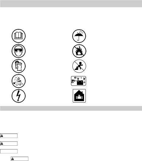
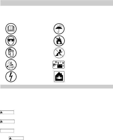
Read manual
before using product.
Protect your eyes.
Wear protective clothing.
Risk of explosive gases.
Risk of electric shock.
Do not expose to rain or snow.
Never smoke or allow flames and sparks.
Keep out of reach of children
Disconnect the main cable before connecting
or disconnecting the clamps.
Use in a well-ventilated area.
1.IMPORTANT SAFETY INSTRUCTIONS – SAVE THESE INSTRUCTIONS.
This manual will show you how to use your charger safely and effectively. Please read, understand and follow these instructions and precautions carefully, as this manual contains important safety and operating instructions. The safety messages used throughout this manual contain a signal word, a message and an icon.
The signal word indicates the level of the hazard in a situation.
Indicates an imminently hazardous situation which, if not avoided, will result in DANGER death or serious injury to the operator or bystanders.
Indicates a potentially hazardous situation which, if not avoided, could result in WARNING death or serious injury to the operator or bystanders.
Indicates a potentially hazardous situation which, if not avoided, could result in IMPORTANT damage to the equipment or vehicle or property damage.
WARNING RISK OF ELECTRIC SHOCK OR FIRE.
1.1To reduce the risk of damage to the electric plug or cord, pull by the plug rather than the cord when disconnecting the charger.
1.2An extension cord should not be used unless absolutely necessary. Use of an improper extension cord could result in a risk of fire and electric shock. If an extension cord must be used, make sure:
•That the pins on the plug of the extension cord are the same number, size and shape as those of the plug on the charger.
•That the extension cord is properly wired and in good electrical condition.
•That the wire size is large enough for the AC ampere rating of the charger as specified in section 7.3.
1.3Do not operate the charger with a damaged cord or plug; have the cord or plug replaced immediately by a qualified service person.
1.4Do not operate the charger if it has received a sharp blow, been dropped or otherwise damaged in any way; take it to a qualified service person.
•2 •

1.5Do not disassemble the charger; take it to a qualified service person when service or repair is required. Incorrect reassembly may result in a risk of fire or electric shock.
WARNING RISK OF EXPLOSIVE GASES.
1.6WORKING IN THE VICINITY OF A LEAD-ACID BATTERY IS DANGEROUS. BATTERIES GENERATE EXPLOSIVE GASES DURING NORMAL BATTERY OPERATION. FOR THIS REASON, IT IS OF UTMOST IMPORTANCE THAT YOU FOLLOW THE INSTRUCTIONS EACH TIME YOU USE THE CHARGER.
1.7To reduce the risk of a battery explosion, follow these instructions and those published by the battery manufacturer and the manufacturer of any equipment you intend to use in the vicinity of the battery. Review the cautionary markings on these products and on the engine.
WARNING Do not use with non-rechargeable batteries. Use only with lead-acid type rechargeable batteries.
2.PERSONAL PRECAUTIONS
WARNING RISK OF EXPLOSIVE GASES.
2.1Remove personal metal items such as rings, bracelets, necklaces and watches when working with a lead-acid battery. A lead-acid battery can produce a short-circuit current high enough to weld a ring or the like to metal, causing a severe burn.
2.2Be extra cautious, to reduce the risk of dropping a metal tool onto the battery. It might spark or short-circuit the battery or other electrical part that may cause an explosion.
2.3Use this charger for charging 12V LEAD-ACID batteries only. It is not intended to supply power to a low voltage electrical system. Do not use this battery charger for charging dry-cell batteries that are commonly used with home appliances. These batteries may burst and cause injury to persons and damage to property.
2.4NEVER charge a frozen battery.
2.5NEVER overcharge a battery.
2.6Consider having someone nearby to come to your aid when you work near a lead-acid battery. Have plenty of fresh water and soap nearby in case battery acid contacts your skin, clothing or eyes.
2.7If battery acid contacts your skin or clothing, immediately wash the area with soap and water. If acid enters your eye, immediately flood the eye with cold running water for at least 10 minutes and get medical attention right away. If battery acid is accidentally swallowed, drink milk, the whites of eggs or water. DO NOT induce vomiting. Seek medical attention immediately.
3.PREPARING TO CHARGE
WARNING RISK OF CONTACT WITH BATTERY ACID. BATTERY ACID IS A HIGHLY CORROSIVE SULFURIC ACID.
3.1Remove all cord wraps and uncoil the cables prior to using the battery charger.
3.2If it is necessary to remove the battery from the vehicle to charge it, always remove the grounded terminal first. Make sure all of the accessories in the vehicle are off to prevent arcing.
3.3Clean the battery terminals before charging the battery. During cleaning, keep airborne corrosion from coming into contact with your eyes, nose and mouth. Use baking soda and water to neutralize the battery acid and help eliminate airborne corrosion. Do not touch your eyes, nose or mouth.
3.4Add distilled water to each cell until the battery acid reaches the level specified by the battery manufacturer. Do not overfill. For a battery without removable cell caps, such as valve regulated lead acid batteries (VRLA), carefully follow the manufacturer’s recharging instructions.
3.5Read, understand and follow all instructions for the charger, battery, vehicle and any equipment used near the battery and charger. Study all of the battery manufacturer’s specific precautions while charging and recommended rates of charge.
3.6Make sure that the charger cable clips make tight connections.
•3 •
4.CHARGER LOCATION
WARNING RISK OF EXPLOSION AND CONTACT WITH BATTERY ACID.
4.1Locate the charger as far away from the battery as the DC cables permit.
4.2Never place the charger directly above the battery being charged; gases from the battery will corrode and damage the charger.
4.3Do not set the battery on top of the charger.
4.4Never allow battery acid to drip onto the charger when reading the electrolyte specific gravity or filling the battery.
5.FOLLOW THESE STEPS WHEN BATTERY IS INSTALLED IN VEHICLE
WARNING A SPARK NEAR THE BATTERY MAY CAUSE A BATTERY EXPLOSION. TO REDUCE THE RISK OF A SPARK NEAR THE BATTERY:
5.1Position the AC and DC cables to reduce the risk of damage by the hood, door and moving or hot engine parts. NOTE: If it is necessary to close the hood during the charging process, ensure that the hood does not touch the metal part of the battery clips or cut the insulation of the cables.
5.2Stay clear of fan blades, belts, pulleys and other parts that can cause injury.
5.3Check the polarity of the battery posts. The POSITIVE (POS, P, +) battery post usually has a larger diameter than the NEGATIVE (NEG, N, -) post.
5.4Determine which post of the battery is grounded (connected) to the chassis.
5.5For a negative-grounded vehicle, connect the POSITIVE (RED) clip from the battery charger to the POSITIVE (POS, P, +) ungrounded post of the battery. Connect the NEGATIVE (BLACK) clip to the vehicle chassis or engine block away from the battery. Do not connect the clip to the carburetor, fuel lines or sheet-metal body parts. Connect to a heavy gauge metal part of the frame or engine block.
5.6For a positive-grounded vehicle, connect the NEGATIVE (BLACK) clip from the battery charger to the NEGATIVE (NEG, N, -) ungrounded post of the battery. Connect the POSITIVE (RED) clip to the vehicle chassis or engine block away from the battery. Do not connect the clip to the carburetor, fuel lines or sheet-metal body parts. Connect to a heavy gauge metal part of the frame or engine block.
5.7Connect charger AC supply cord to electrical outlet.
5.8When disconnecting the charger, disconnect the AC cord, remove the clip from the vehicle chassis and then remove the clip from the battery terminal.
5.9See CALCULATING CHARGE TIME for length of charge information.
6.FOLLOW THESE STEPS WHEN BATTERY IS OUTSIDE VEHICLE
WARNING A SPARK NEAR THE BATTERY MAY CAUSE A BATTERY EXPLOSION. TO REDUCE THE RISK OF A SPARK NEAR THE BATTERY:
6.1Check the polarity of the battery posts. The POSITIVE (POS, P, +) battery post usually has a larger diameter than the NEGATIVE (NEG, N, -) post.
6.2Attach at least a 24-inch (61 cm) long 6-gauge (AWG) insulated battery cable to the NEGATIVE (NEG, N, -) battery post.
6.3Connect the POSITIVE (RED) charger clip to the POSITIVE (POS, P, +) post of the battery.
6.4Position yourself and the free end of the cable you previously attached to the NEGATIVE (NEG, N, -) battery post as far away from the battery as possible – then connect the NEGATIVE (BLACK) charger clip to the free end of the cable.
6.5Do not face the battery when making the final connection.
6.6Connect charger AC supply cord to electrical outlet.
6.7When disconnecting the charger, always do so in the reverse order of the connecting procedure and break the first connection while as far away from the battery as practical.
6.8A marine (boat) battery must be removed and charged on shore. To charge it onboard requires equipment specially designed for marine use.
•4 •
7. GROUNDING AND AC POWER CORD CONNECTIONS WARNING RISK OF ELECTRIC SHOCK OR FIRE.
7.1This battery charger is for use on a nominal 230V, 50 Hz circuit. (See the warning label on the charger for the correct input voltage.) The plug must be plugged into an outlet that is properly installed and grounded in accordance with all local codes and ordinances. The plug pins must fit the receptacle (outlet). Do not use with an ungrounded system.
7.2 |
DANGER Never alter the AC cord or plug provided – if it does not fit the outlet, have |
|
a proper grounded outlet installed by a qualified electrician. An improper connection can |
result in a risk of an electric shock or electrocution.
7.3Recommended minimum AWG size for extension cord:
•100 feet (30.5 meters) long or less – use a 10 gauge (6 mm2) extension cord.
•Over 100 feet (30.5 meters) long – use an 8 gauge (10 mm2) extension cord.
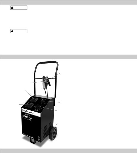
8.FEATURES
 3 4
3 4
|
5 |
1. |
Ammeter |
|
2 |
2. |
Voltmeter |
|
3. |
Foam Grip |
|
|
|
||
|
|
4. |
Fiberglass Clamp Rod |
1 |
6 |
5. |
Battery Clamps |
|
6. |
Charge Rate Selector Switch |
|
|
|
||
|
7 |
7. |
Timer |
|
|
8. |
Wheel |
|
8 |
|
|
9.ASSEMBLY INSTRUCTIONS
It is important to fully assemble your charger before use. Follow these instructions for assembly.
Item |
|
PARTS |
TOOLS NEEDED |
1 |
(2) axle brackets |
3/8" wrench (for mounting foot) |
|
2 |
(1) axle with pin holes |
5/16" wrench (for mounting wheels) |
|
3 |
(2) wheels |
1/4" wrench (for mounting handle) |
|
4 |
(2) |
10-32, thread cutting screws |
hammer |
5 |
(2) |
¼-20, thread cutting screws |
screwdriver (flat blade) |
6 |
(1) foot |
screwdriver (Phillips) |
|
7 |
(2) axle caps |
|
|
8 |
(2) hairpin cotter |
|
|
9 |
(4) |
8-18 sheet metal screws |
|
10 |
(1) handle |
|
|
11 |
(1) fiberglass clamp rod |
|
|
12 |
(1) foam handle grip |
|
|
• 5 •
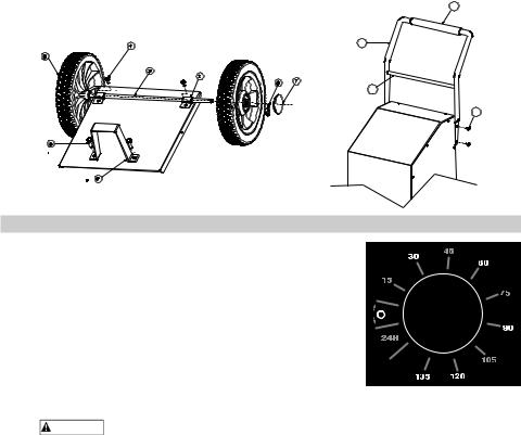
1.Carefully lay the charger on its front to prepare for assembly.
2.Assemble the foot (Item 6) using two ¼-20 screws (Item 5) and tighten securely.
3.Attach the two axle brackets (Item 1) using one 10-32 screw (Item 4) in each. The brackets should have one end hooked into the slot in the charger base. Be careful not to drop the brackets inside of the charger case. Do not completely tighten the screws (Item 4) at this time.
4.Slide the axle (Item 2) into the brackets (Item 1) until centered on the charger.
5.Slide one wheel (Item 3) onto the axle with the recessed hub facing out as shown.
6.Insert the pin (Item 8) through the axle hole.
7.Repeat this process for the other wheel and when both wheels have been pinned to the axle, finish tightening the two axle bracket screws (Item 4).
8.Snap the axle caps (Item 7) onto each wheel to cover the pin and axle.
9.Lift the charger upright so that it rests on the wheels and foot.
10.Remove the two top side screws (Item 9) from each side of the charger.
11.Verify that the foam handle grip (Item 12) is on the handle assembly (Item 10). Install if needed.
12.Insert the fiberglass clamp rod (Item 11) into the pierced holes on the inside of the handle (Item 10).
13.Align the handle assembly (Item 10) with charger and reinstall the side screws (Item 9). Do not over tighten.
14.The charger assembly is now complete. The battery clips can be clamped to the fiberglass rod (Item 11) for convenient storage.
15.Do not attach the clips to the foam area of the handle; this will damage the foam grip.
12
10
11
9
10.CONTROL PANEL
Timer
Timer Setting: The timer allows you to set a specified
time for charging. After the timer expires, the charger stops charging your battery. The main function of the timer
is to prevent overcharging while allowing a battery time to obtain a satisfactory charge. To properly set the timer,
you must know the size of the battery in ampere hours or reserve capacity in minutes and the state of charge. It
is important that you determine the appropriate state of charge of your battery as specified in Section 12 and set
the timer accordingly.
24H (Hold): This position defeats the timer function, allowing for continuous operation. Put the timer in the 24H position when you want to charge more than 2¼ hours.
WARNING Be sure to monitor the charging progress and stop it when the battery is charged. Not doing so may cause damage to your battery or may cause other personal property damage or personal injury. • 6 •

Ammeter
The Ammeter indicates the amount of current, measured in amps, that is being drawn by the battery. As a battery takes on a charge, it draws less current from the charger. Correspondingly, the meter will show less current being drawn by the battery. When the current stops decreasing, the battery is charged. The 4 amp charge rate may indicate some activity on the meter, although the meter does not have the resolution to display this low rate.
Voltmeter
The voltmeter indicates the voltage at the battery terminals. The charger need not be plugged into an AC outlet. The timer should be in the OFF position. Then connect the charger following the instructions in Sections 5 and 6. Observe the meter indication.
Keep in mind that this reading is only a battery voltage reading; a false surface charge may mislead you. We suggest that you turn on the headlights for a couple of minutes before you read the meter. Read it a few minutes after you have shut off the headlights. If the reading is less than 10.5 volts, the battery may be bad or the connection at the charger may be poor. If the reading is 10.5–12.5 volts, the battery is low – recharge it. If the reading is above 12.8 volts, the battery is charged.
Charge Rate Selector Switch
Use the Charge Rate selector switch to select the charge rate or engine starting setting you require.
• 4A Slow Charge Rate – For charging small batteries, such as those commonly used in garden tractors, snowmobiles and motorcycles.
•20A and 40A Fast and 70A Rapid Charge Rate –
For charging automotive, marine and deep-cycle
batteries. Not intended for industrial applications.
• 350A Engine Start – Provides 350 amps for cranking an engine with a weak or run-down battery. Always use in combination with a battery.
11.OPERATING INSTRUCTIONS
Thermal Runaway
As a safety precaution, the charger automatically reduces the current if it detects that the battery may be getting too hot.
Charging
1.Ensure that all of the charger components are in place and in good working condition, including the plastic boots on the battery clips. Make sure the electrolyte (battery liquid) in each cell is at the correct level.
2.Set the charge rate switch and the timer to the OFF position.
3.Connect the battery following the precautions listed in Sections 5 and 6.
4.Connect the AC power following the precautions listed in Section 7.
5.Select the desired charge rate. NOTE: The 40 amp Manual rate is a manual mode and will overcharge a battery if permitted to operate for extended periods of time. Monitor the charging process often.
6.Turn the timer to 24H (Hold) or the selected charge time if using the 40 amp Manual Mode.
7.To disconnect the charger, reverse the procedure.
NOTE: This charger is equipped with a safe start feature. In the Automatic 4, 20 and 70 amp charge rates, it will not supply current to the battery clips until a battery is properly connected. Unlike traditional chargers, the clips will not spark if touched together. In the Manual 40 amp charge rate, the clips will spark if accidently touched together.
Automatic Charging Modes
Put the timer in the 24H (Hold) position when using the battery charger in one of the Automatic Modes (4, 20 or 70 amp), otherwise the timer will stop the charging process when the time expires regardless of whether it is complete or not. The CHARGED (green) LED will light when charging is complete and the charger goes into Maintain Mode. The charger will not shut off. For a battery with a starting voltage under 1 volt, use the Manual Mode (see Manual Charging section) first to pre-charge the battery for five minutes, to get additional voltage into the battery for the charger to analyze.
• 7 •
Manual Charging Mode
When you select the 40 Amp Manual Mode charge rate, you will be charging in manual mode. You must set the timer to the proper time (see Timer section). If you want to charge more than 2¼ hours, then set the timer in the 24H position. Be sure to monitor the charging procedure and stop it when the battery is charged. Not doing so may cause damage to your battery or result in other property damage or personal injury.
Aborted Charge
If charging can not be completed normally, charging will abort. When charging aborts, the charger’s output is shut off. To reset after an aborted charge, either disconnect the battery or unplug the charger.
Completion of Charge
Charge completion is indicated by the CHARGED (green) LED. When lit, the charger has switched to the Maintain Mode of operation.
Maintain Mode (Float-Mode Monitoring)
When the CHARGED (green) LED is lit, the charger has started Maintain Mode. In this mode, the charger keeps the battery fully charged by delivering a small current when necessary. If the battery voltage drops below a preset level, the charger will go back into Charge Mode until the battery voltage returns to the full charge level, at which point the charger will return to Maintain Mode.
Using the Engine Start feature
Your battery charger can be used to jumpstart your car if the battery is low. Follow these instructions on how to use the ENGINE START feature.
This product is rated for 3 seconds of engine cranking.
WARNING Follow all safety instructions and precautions for charging your battery. Wear complete eye protection and clothing protection. Charge your battery in a well-ventilated area.
IMPORTANT Using the ENGINE START feature WITHOUT a battery installed in the vehicle could cause damage to the vehicle’s electrical system. NOTE: If you have charged the battery and it still will not start your car, do not use the engine start feature, or it could damage the vehicle’s electrical system.
IMPORTANT Do not leave the charger in ENGINE START Mode for more than ten minutes at a time; this may damage the charger.
1.Set the charge rate switch and the timer to the OFF position.
2.With the charger unplugged from the AC outlet, connect the charger to the battery following the instructions given in Section 5 (FOLLOW THESE STEPS WHEN THE BATTERY IS INSTALLED IN A VEHICLE).
3.Plug the charger AC power cord into the AC outlet, and then move the timer switch from OFF to the 24H position.
4.With the charger plugged in and connected to the battery of the vehicle, set the charge rate selector switch to the engine start position.
5.Crank the engine until it starts or 3 seconds pass. If the engine does not start, wait 3 minutes before cranking again. This allows the charger and battery to cool down.
NOTE: During extremely cold weather, or if the battery is under 2 volts, charge the battery for 5 minutes before cranking the engine.
6.If the engine fails to start, charge the battery for 5 more minutes before attempting to crank the engine again.
7.After the engine starts, move the charge rate selector switch to the OFF position and unplug the AC power cord before disconnecting the battery clips from the vehicle.
8.Clean and store the charger in a dry location.
NOTE: If the engine does turn over but never starts, there is not a problem with the starting system; there is a problem somewhere else with the vehicle. STOP cranking the engine until the other problem has been diagnosed and corrected.
• 8 •

Using the Battery Voltage Tester
Overview
This battery charger has a built-in voltmeter to test your battery’s state of charge. The charger does not have a built in load tester. As such, a recently charged battery could have a temporarily high voltage due to what is known as “surface charge”. The voltage of such a battery will gradually drop during the period immediately after the charging system is disengaged. Consequently, the tester could display inconsistent values for such a battery. For a more accurate reading, the surface charge should be removed by temporarily creating a load on the battery, such as by turning on lights or other accessories for a couple of minutes before you read the display. Read it a couple of minutes after you have shut the headlights off.
Testing Sequence: There are four basic steps required to test the battery state of charge:
1.With the charger unplugged from the AC outlet, connect the charger to the battery following the instructions given in Sections 5 and 6.
2.Set the charge rate switch and the timer to the OFF position.
3.Plug the charger AC power cord into the AC outlet, following the instructions given in Section 7.
4.Read the voltage on the voltmeter.
General Charging Notes
Fan: The charger is designed to control its cooling fan for efficient operation. It is normal for the fan to start and stop when maintaining a fully charged battery. Keep the area near the charger clear of obstructions to allow the fan to operate efficiently.
Voltage: The voltage displayed during charging is the charging voltage and is usually higher than the battery’s resting voltage.
12.CALCULATING CHARGE TIME
Use the following table to determine the time it will take to bring a battery to full charge.
First, identify where your battery fits into the chart.
NR means that the charger setting is NOT RECOMMENDED.
Find your battery’s rating on the chart below, and note the charge time given for each charger setting. The times given are for batteries with a 50% charge prior to recharging. Add more time for severely discharged batteries.
BATTERY SIZE/RATING |
CHARGE RATE/CHARGING TIME |
||||||
4 AMP |
20 AMP |
40 AMP |
70 AMP |
||||
|
|
|
|||||
SMALL |
Motorcycle, |
6 - 12 AH |
1 - 2 hrs |
NR |
NR |
NR |
|
garden, |
|
|
|
|
|
||
BATTERIES |
12 - 32 AH |
2 - 5 hrs |
NR |
NR |
NR |
||
tractor, etc. |
|||||||
|
200 - 315 CCA |
40 - 60 RC |
5½ - 7¼ hrs |
1 - 1½ hrs |
½ - ¾ hr |
20 - 30 min |
|
CARS/ |
315 - 550 CCA |
60 - 85 RC |
7¼ - 9¼ hrs |
1½ - 2 hrs |
¾ - 1 hr |
30 - 40 min |
|
TRUCKS |
|
|
|
|
|
|
|
550 - 1000 CCA |
80 - 190 RC |
9¼ - 17½ |
2 - 3½ hrs |
1 - 1¾ hrs |
40 min - 1 hr |
||
|
|||||||
|
hrs |
||||||
|
|
|
|
|
|
||
|
|
80 RC |
8¾ hrs |
1¾ hrs |
NR |
NR |
|
MARINE/DEEP-CYCLE |
140 RC |
13½ hrs |
2¾ hrs |
NR |
NR |
||
160 RC |
15 hrs |
3 hrs |
NR |
NR |
|||
|
|
||||||
|
|
180 RC |
16½ hrs |
3½ hrs |
NR |
NR |
|
• 9 •

13.MAINTENANCE INSTRUCTIONS
13.1After use and before performing maintenance, unplug and disconnect the battery charger (see sections 5, 6 and 7).
13.2Use a dry cloth to wipe all battery corrosion and other dirt or oil from the battery clips, cords and the charger case.
13.3Ensure that all of the charger components are in place and in good working condition, for example, the plastic boots on the battery clips.
13.4Servicing does not require opening the unit, as there are no user-serviceable parts.
13.5All other servicing should be performed by qualified service personnel.
14. STORAGE INSTRUCTIONS
14.1 Store the charger unplugged, in an upright position. The cord will still conduct electricity until it is unplugged from the outlet.
14.2 If the charger is moved around the shop or transported to another location, take care to avoid/prevent damage to the cords, clips and charger. Failure to do so could result in personal injury or property damage. Store the clips on the fiberglass clamp rod. Do not store them on the handle, clipped together, on or around metal, or clipped to the cables.
15. TROUBLESHOOTING
PROBLEM |
POSSIBLE CAUSE |
REASON/SOLUTION |
No reading on the |
Charger is not plugged in. |
Plug the charger into an AC outlet. |
ammeter. |
No power at the receptacle. |
Check for open fuse or circuit breaker |
|
||
|
|
supplying AC outlet. |
|
Clips are not making a good |
Check for poor connection to battery and |
|
connection to the battery. |
frame. Make sure connection points are |
|
|
clean. Rock clips back and forth for a |
|
|
better connection. |
|
Connections are reversed. |
Unplug the charger and reverse the clips. |
|
Battery is defective (will not |
Have battery checked. |
|
accept a charge). |
|
|
4 amp charge rate is being used. |
Ammeter may show no activity at the 4A |
|
|
charge rate. |
Ammeter reading |
Battery is severely discharged. |
Continue charging battery for two more |
stays high. |
|
hours. If problem continues, have the |
|
|
battery checked. |
Ammeter reads |
Extension cord is too long or |
Use a shorter or heavier gauge extension |
less than selected |
wire gauge is too small. |
cord. |
charge rate |
Weak cell or sulfated plate in |
A sulfated battery will eventually take a |
when charging a |
||
discharged battery |
battery. |
normal charge if left connected. If the |
|
|
battery will not take a charge, have it |
|
|
checked. |
|
Battery is only partially |
Continue to charge the battery. |
|
discharged. |
|
Battery clips do not |
The charger is equipped with |
No problem; this is a normal condition. |
spark when touched |
a safe start feature. In the |
|
together. |
automatic modes, it will not |
|
|
supply current to the battery |
|
|
clips until a battery is properly |
|
|
connected. Unlike traditional |
|
|
chargers, the clips will not spark |
|
|
if touched together. (In manual |
|
|
mode, the clips should spark.) |
|
• 10 •
PROBLEM |
POSSIBLE CAUSE |
REASON/SOLUTION |
The charger is |
Circuit breaker is cycling. |
The settings may be wrong. Check the |
making an audible |
|
charger settings. |
clicking sound. |
Battery is defective. |
Have the battery checked. |
|
||
|
Shorted battery cables or clips. |
Circuit breaker cycles when current draw |
|
|
is too high. Check for shorted cables or |
|
|
clips and replace if necessary. |
|
Severely discharged battery, |
The battery may not want to accept a |
|
but otherwise it is a good |
charge due to a run-down state. Allow |
|
battery. |
charging to continue until battery has a |
|
|
chance to recover sufficiently to take a |
|
|
charge. If more than 20 minutes, stop |
|
|
charging and have the battery checked. |
|
Reverse connections at battery. |
Shut the charger off and correct the lead |
|
|
connections. |
Charger makes a |
Transformer laminations vibrate |
No problem; this is a normal condition. |
loud buzz or hum. |
(buzz). |
|
|
Shorted Diode Assembly or |
Have charger checked by a qualified |
|
Output Rectifier Assembly |
technician. |
|
(hum). |
|
Short or no start |
Drawing more than 350 amps. |
Crank time varies with the amount of |
cycle when cranking |
|
current drawn. If cranking draws more |
engine. |
|
than 350 amps, crank time may be less |
|
|
than 3 seconds. |
|
Failure to wait 3 minutes (180 |
Wait 3 minutes of rest time before the |
|
seconds) between cranks. |
next crank. |
|
Clips are not making a good |
Check for poor connection at battery |
|
connection. |
and frame. |
|
AC cord and/or extension cord |
Check power cord and extension cord for |
|
is loose. |
loose fitting plug. |
|
No power at receptacle. |
Check for open fuse or circuit breaker |
|
|
supplying AC outlet. |
|
The charger may be |
The thermal protector may have tripped |
|
overheated. |
and needs a little longer to reset. Make |
|
|
sure the charger vents are not blocked. |
|
|
Wait and try again. |
|
Battery may be severely |
On a severely discharged battery, charge |
|
discharged. |
for 10 to 15 minutes in the 40 amp |
|
|
manual rate to help assist in cranking. |
Charger will not turn |
AC outlet is dead. |
Check for open fuse or circuit breaker |
on when properly |
|
supplying AC outlet. |
connected. |
Blown Fuse. |
Replace the fuse (15 Amp fuse). |
|
||
|
Poor electrical connection. |
Check power cord and extension cord for |
|
|
loose fitting plug. |
The battery is |
Clips are not making a good |
Check for poor connection at battery and |
connected and the |
connection. |
frame. Make sure connecting points are |
charger is on, but is |
|
clean. Rock clips back and forth for a |
not charging. |
|
better connection. |
The measured |
The charger reached the |
No problem; this is a normal condition. |
current is much |
maximum voltage and is |
|
lower than what was |
reducing the current. |
|
selected. |
|
|
• 11 •

16.SPECIFICATIONS
Input |
230V ~ 7A, 50Hz, Max 19A/5 sec., |
|
|
|
|
|
15A |
||
|
|
|
|
|
|||||
Output (Charge) |
12V |
|
4A, 20A, 40A, 70A |
|
|
|
|
|
|
|
|
|
|
|
|
||||
Output (Engine Start) |
12V |
|
Max 220A/5 sec. |
|
|
|
|
|
|
|
|
|
|
|
|
||||
Weight |
44.75 lbs. (20.30 kg) |
|
|
|
|
|
|||
17.LIMITED WARRANTY
SCHUMACHER ELECTRIC CORPORATION, 801 BUSINESS CENTER DRIVE, MOUNT PROSPECT, IL 60056-2179, MAKES THIS LIMITED WARRANTY TO THE ORIGINAL RETAIL PURCHASER OF THIS PRODUCT. THIS LIMITED WARRANTY IS NOT TRANSFERABLE OR ASSIGNABLE.
Schumacher Electric Corporation (the “Manufacturer”) warrants this battery charger for 2 years from the date of purchase at retail against defective material or workmanship that may occur under normal use and care. If your unit is not free from defective material or workmanship, Manufacturer’s obligation under this warranty is solely to repair or replace your product with a new or reconditioned unit at the option of the Manufacturer. It is the obligation of the purchaser to forward the unit, along with proof of purchase and mailing charges prepaid to the Manufacturer or its authorized representatives in order for repair or replacement to occur.
Manufacturer does not provide any warranty for any accessories used with this product that are not manufactured by Schumacher Electric Corporation and approved for use with this product. This Limited Warranty is void if the product is misused, subjected to careless handling, repaired, or modified by anyone other than Manufacturer or if this unit is resold through an unauthorized retailer.
Manufacturer makes no other warranties, including, but not limited to, express, implied or statutory warranties, including without limitation, any implied warranty of merchantability or implied warranty of fitness for a particular purpose. Further,
Manufacturer shall not be liable for any incidental, special or consequential damage claims incurred by purchasers, users or others associated with this product, including, but not limited to, lost profits, revenues, anticipated sales, business opportunities, goodwill, business interruption and any other injury or damage. Any and all such warranties, other than the limited warranty included herein, are hereby expressly disclaimed and excluded. Some states do not allow the exclusion or limitation of incidental or consequential damages or length of implied warranty, so the above limitations or exclusions may not apply to you. This warranty gives you specific legal rights and it is possible you may have other rights which vary from this warranty.
THIS LIMITED WARRANTY IS THE ONLY EXPRESS LIMITED WARRANTY AND THE MANUFACTURER NEITHER ASSUMES OR AUTHORIZES ANYONE TO ASSUME OR MAKE ANY OTHER OBLIGATION TOWARDS THE PRODUCT OTHER THAN THIS WARRANTY.
Warranty, Repair Service and Distribution Centers:
For customers outside of the U.S.A., contact your local distributor. North and South America: Hoopeston in U.S.A. 1-800-621-5485 services@schumacherelectric.com
Europe: Freightways in Netherlands +31 71 4090704 customerservice@freightways.nl
Schumacher® and the Schumacher Logo are registered trademarks of Schumacher Electric Corporation.
• 12 •

|
DECLARATION OF CONFORMITY |
We, |
Schumacher Electric Corporation |
|
801 East Business Center Drive |
|
Mount Prospect, Illinois, 60056, U.S.A. |
certify that the Automatic Battery Charger Model PWI70300A complies with the following standards:
Low Voltage Directive (LVD) 2006/95/EC,
EN 60335-1:2002 + A1:2004 + A2:2006 + A11:2004 + A12:2006 + A13:2008 EN 60335-2-29:2004
89/336/EEC and 93/68/EEC
and therefore conforms with the protection requirements relating to safety and electromagnetic compatibility.
The year in which the CE marking was affixed is “2012”.
Manufacturer:
John Waldron
President
April 6, 2012
Hereby declares that the equipment Model PWI70300A is compliant to the DIRECTIVE 2002/95/EC OF THE EUROPEAN PARLIAMENT AND OF THE COUNCIL of 27 January 2003 (RoHS) on the restriction of the use of certain hazardous substances in electrical and electronic equipment while:
The parts do not exceed the maximum concentrations of 0.1% by weight in homogenous materials for lead, mercury, hexavalent chromium, polybrominated biphenyls (PBB)
and polybrominated diphenyl ethers (PBDE), and 0.01% for cadmium, as required in Commission Decision 2005/618/EC of 18 August 2005.
April 6, 2012
President, Schumacher Electric Corporation – U.S.A.
• 13 •
DEUTSCH
Modell: PWI70300A
Automatisches Batterieladegerät
BENUTZERANLEITUNG
Vor der Verwendung dieses Produkts ist die Anleitung zu lesen.
Augenschutz tragen.
Schutzkleidung tragen.
Explosionsgefahr.
Stromschlaggefahr.
Weder Regen noch Schnee aussetzen.
Niemals in der Nähe rauchen und vor Flammen und Funken schützen.
Von Kindern fernhalten.
Vor dem Anschließen oder Trennen der Klemmen das Hauptkabel trennen.
In einem gut belüfteten Bereich verwenden.
1.WICHTIGE SICHERHEITSHINWEISE – DIESE ANLEITUNG AUFBEWAHREN.
Diese Anleitung beschreibt den sicheren und wirkungsvollen Gebrauch des Ladegeräts. Diese Anleitung enthält wichtige Sicherheitsund Bedienungsanweisungen. Machen Sie sich mit diesen Anweisungen und Vorsichtshinweisen vollständig vertraut. Die in dieser Anleitung verwendeten Sicherheitshinweise enthalten ein Signalwort, einen Hinweis und ein Symbol.
Das Signalwort kennzeichnet die Gefahrenstufe in einer bestimmten Situation.
Kennzeichnet eine unmittelbar gefährliche Situation, die, wenn sie nicht
GEFAHR vermieden wird, zu schweren oder tödlichen Verletzungen beim Bediener oder bei umstehenden Personen führen kann.
Kennzeichnet eine potenziell gefährliche Situation, die, wenn sie nicht vermieden ACHTUNG wird, zu schweren oder tödlichen Verletzungen beim Bediener oder bei
umstehenden Personen führen kann.
Kennzeichnet eine potenziell gefährliche Situation, die, wenn sie nicht vermieden WICHTIG wird, zu einer Beschädigung der Geräte, von Fahrzeugen oder der Einrichtung
führen kann.
ACHTUNG STROMSCHLAGODER BRANDGEFAHR.
1.1Um die Gefahr von Schäden am Stecker oder Kabel zu reduzieren, beim Trennen des Ladegeräts stets am Stecker selbst und nicht am Kabel ziehen.
1.2Ein Verlängerungskabel nur dann verwenden, wenn dies absolut notwendig ist. Die Verwendung eines ungeeigneten Verlängerungskabels kann die Gefahr eines
Brandes oder Stromschlags zur Folge haben. Muss ein Verlängerungskabel verwendet werden, ist Folgendes zu gewährleisten:
•Die Kontakte am Stecker des Verlängerungskabels entsprechen in Anzahl, Größe und Form denen am Stecker des Ladegeräts.
•Das Verlängerungskabel ist ordnungsgemäß verdrahtet und in einem guten elektrischen Zustand.
•Die Größe des Leiters reicht für die in Abschnitt 7.3 angegebene Amperezahl des Ladegeräts aus.
•14 •
1.3Das Ladegerät nicht verwenden, wenn das Kabel oder der Stecker beschädigt ist.
In diesem Fall Kabel oder Stecker sofort von einem qualifizierten Servicetechniker ersetzen lassen.
1.4Das Ladegerät nicht verwenden, wenn es einem schweren Schlag ausgesetzt, fallen gelassen oder auf sonstige Weise beschädigt wurde. Bringen Sie es in diesem Fall zu einem qualifizierten Servicetechniker.
1.5Das Ladegerät nicht zerlegen. Bei Wartungsoder Reparaturbedarf zu einem qualifizierten Servicetechniker bringen. Bei einem unsachgemäßen Zusammenbau besteht Brandoder Stromschlaggefahr.
ACHTUNG GEFAHR EXPLOSIVER GASE.
1.6DAS ARBEITEN IN UNMITTELBARER NÄHE VON BLEISÄUREBATTERIEN IST GEFÄHRLICH. BATTERIEN ERZEUGEN WÄHREND DES NORMALBETRIEBS EXPLOSIVE GASE. AUS DIESEM GRUND MÜSSEN BEI JEDER VERWENDUNG DES LADEGERÄTS UNBEDINGT ALLE ANWEISUNGEN BEFOLGT WERDEN.
1.7Um das Risiko einer Batterieexplosion zu reduzieren, den folgenden Anweisungen und der vom Batteriehersteller und dem Hersteller aller anderen Geräte veröffentlichten Anleitung folgen, die in der Nähe der Batterie eingesetzt werden. Die Vorsichtshinweise an diesen Produkten und am Motor beachten.
ACHTUNG Nicht mit nicht aufladbaren Batterien verwenden. Nur mit aufladbaren
Bleisäurebatterien verwenden.
2. HINWEISE ZUM SCHUTZ VOR VERLETZUNGEN
ACHTUNG GEFAHR EXPLOSIVER GASE.
2.1Beim Arbeiten an Bleisäurebatterien Schmuck oder andere Metallgegenstände wie Ringe, Armreifen, Halsketten und Uhren abnehmen. Die von Bleisäurebatterien erzeugten Kurzschluss-Ströme können so stark sein, dass Ringe oder ähnliche Gegenstände mit Metall verschweißt werden, wodurch schwere Verbrennungen entstehen können.
2.2Insbesondere ist darauf zu achten, dass keine Metallwerkzeuge auf die Batterie fallen. Die dadurch entstehende Funkenbildung oder ein Kurzschluss der Batterie oder anderer Elektroteile kann zu einer Explosion führen.
2.3Dieses Ladegerät nur zum Laden von 12V BLEISÄURE-Batterien verwenden. Es ist nicht für die Stromversorgung eines elektrischen Niederspannungssystems vorgesehen. Dieses
Batterieladegerät nicht zum Aufladen von Trockenzellenbatterien verwenden, wie sie oft in Haushaltsgeräten verwendet werden. Solche Batterien können bersten und dadurch Körperverletzungen und Sachbeschädigungen verursachen.
2.4NIEMALS eine eingefrorene Batterie aufladen.
2.5Eine Batterie NIEMALS überladen.
2.6Ziehen Sie in Erwägung, Ihre Arbeiten in der Nähe einer Bleisäurebatterie nur dann zu verrichten, während sich eine andere Person in der Nähe aufhält. Für den Fall, dass Batteriesäure mit Haut, Kleidung oder Augen in Kontakt kommt, viel frisches Wasser und Seife bereithalten.
2.7Falls Batteriesäure mit Ihrer Haut oder Kleidung in Kontakt kommt, den betroffenen Bereich sofort mit Wasser und Seife waschen. Falls Säure in die Augen gelangt, diese mindestens 10 Minuten lang mit fließendem kaltem Wasser spülen und sofort einen Arzt hinzuziehen. Wird Batteriesäure versehentlich verschluckt, Milch, Eiweiß oder Wasser trinken. KEIN Erbrechen herbeiführen. Sofort einen Arzt aufsuchen.
3.VORBEREITEN AUF DAS LADEN
ACHTUNG RISIKO DES KONTAKTS MIT BATTERIESÄURE. BEI BATTERIESÄURE HANDELT ES SICH UM STARK KORROSIVE SCHWEFELSÄURE.
3.1Alle Kabelhüllen entfernen und die Kabel vor Verwendung des Batterieladegeräts abwickeln.
3.2Falls die Batterie zum Aufladen aus dem Fahrzeug entfernt werden muss, stets den geerdeten Anschluss zuerst abtrennen. Alle Zubehörteile im Fahrzeug müssen abgeschaltet sein, um eine Bogenbildung zu verhindern.
•15 •

3.3Batterieanschlüsse vor dem Aufladen reinigen. Während des Reinigens verhindern, dass Korrosionspartikel in der Luft in Kontakt mit Augen, Nase oder Mund kommen. Batteriesäure mit Backnatron und Wasser neutralisieren, um ein Freisetzen von Korrosionspartikeln in die Luft zu verhindern. Augen, Nase oder Mund nicht berühren.
3.4Destilliertes Wasser in jede Zelle füllen, bis die Batteriesäure den vom Batteriehersteller vorgegebenen Pegel erreicht. Nicht überfüllen. Bei einer Batterie ohne abnehmbare Zellkappen, wie z. B. einer verschlossenen VRLA-Bleisäurebatterie, ist die Anleitung des Herstellers zum Aufladen einzuhalten.
3.5Machen Sie sich mit allen Anleitungen zum Ladegerät, zur Batterie, zum Fahrzeug und zu anderen Geräten vertraut, die in der Nähe der Batterie bzw. des Ladegeräts verwendet werden, und halten Sie sich an alle Anweisungen. Machen Sie sich mit allen spezifischen Vorsichtshinweisen zum Wiederaufladen und den empfohlenen Aufladegeschwindigkeiten des Batterieherstellers vertraut.
3.6Die Kabelklemmen des Ladegeräts müssen fest angeschlossen sein.
4.POSITION DES LADEGERÄTS
ACHTUNG EXPLOSIONSGEFAHR UND GEFAHR DES KONTAKTS MIT BATTERIESÄURE.
4.1Das Ladegerät so weit von der Batterie entfernt aufstellen, wie die Länge der Gleichstromkabel dies zulässt.
4.2Das Ladegerät nie direkt über der zu ladenden Batterie aufstellen. Gase aus der Batterie führen zu Korrosion und damit zur Beschädigung des Ladegeräts.
4.3Die Batterie nicht auf das Ladegerät stellen.
4.4Batteriesäure nicht auf das Ladegerät tropfen lassen, wenn die Elektrolytdichte gemessen oder die Batterie gefüllt wird.
5.FOLGENDE SCHRITTE DURCHFÜHREN, WENN DIE BATTERIE IM FAHRZEUG INSTALLIERT IST
ACHTUNG EIN FUNKEN IN DER NÄHE DER BATTERIE KANN EINE BATTERIEEXPLOSION VERURSACHEN. SO WIRD DAS RISIKO VON FUNKEN IN DER NÄHE DER BATTERIE REDUZIERT:
5.1Die Wechselund Gleichstromkabel so positionieren, dass das Risiko einer Beschädigung durch Motorhaube, Tür und angetriebene oder heiße Motorteile reduziert wird. HINWEIS: Falls die Motorhaube während des Ladevorgangs geschlossen werden muss, muss gewährleistet werden, dass sie keine Metallteile der Batterieklemmen berührt und die Kabelisolierung nicht beschädigt.
5.2Von Lüfterflügeln, Riemen, Scheiben und anderen Teilen, die Verletzungen verursachen können, fernhalten.
5.3Die Polarität der Batteriekontakte prüfen. Der POSITIVE (POS, P, +) Batteriekontakt weist in der Regel einen größeren Durchmesser auf als der NEGATIVE (NEG, N, -).
5.4Bestimmen, welcher Batteriekontakt über das Chassis geerdet (mit dem Chassis verbunden) ist.
5.5Bei einem über den negativen Kontakt geerdeten Fahrzeug die POSITIVE (ROTE) Klemme des Batterieladegeräts mit dem ungeerdeten POSITIVEN (POS, P, +) Kontakt der Batterie verbinden. Die NEGATIVE (SCHWARZE) Klemme in einiger Entfernung von der Batterie mit dem Fahrzeugchassis oder Motorblock verbinden. Die Klemme nicht mit dem Vergaser, den Kraftstoffleitungen oder den Blechteilen verbinden. Die Klemme statt dessen mit einem schweren, dicken Metallteil, das zum Rahmen oder Motorblock gehört, verbinden.
5.6Bei einem über den positiven Kontakt geerdeten Fahrzeug die NEGATIVE (SCHWARZE) Klemme des Batterieladegeräts mit dem nicht geerdeten NEGATIVEN (NEG, N, -) Kontakt der Batterie verbinden. Die POSITIVE (ROTE) Klemme in einiger Entfernung von der Batterie mit dem Fahrzeugchassis oder Motorblock verbinden.
Die Klemme nicht mit dem Vergaser, den Kraftstoffleitungen oder den Blechteilen verbinden. Die Klemme statt dessen mit einem schweren, dicken Metallteil, das zum Rahmen oder Motorblock gehört, verbinden.
•16 •
5.7Das Netzstromkabel des Ladegeräts an einer Steckdose anschließen.
5.8Wenn das Ladegerät abgetrennt wird, das Netzstromkabel abtrennen, die Klemme vom Fahrzeugchassis entfernen und dann die Klemme vom Batteriekontakt trennen.
5.9Informationen zur Ladezeit finden Sie unter BERECHNEN DER LADEZEIT
6.FOLGENDE SCHRITTE DURCHFÜHREN, WENN DIE BATTERIE NICHT IM FAHRZEUG INSTALLIERT IST
ACHTUNG EIN FUNKEN IN DER NÄHE DER BATTERIE KANN EINE BATTERIEEXPLOSION VERURSACHEN. SO WIRD DAS RISIKO VON FUNKEN IN DER NÄHE DER BATTERIE REDUZIERT:
6.1Die Polarität der Batteriekontakte prüfen. Der POSITIVE (POS, P, +) Batteriekontakt weist in der Regel einen größeren Durchmesser auf als der NEGATIVE (NEG, N, -).
6.2Schließen Sie ein mindestens 61 cm langes, isoliertes Batteriekabel (4,115 mm Durchmesser, AWG 6) am NEGATIVEN (NEG, N, -) Batteriekontakt an.
6.3Die POSITIVE (ROTE) Klemme des Ladegeräts mit dem POSITIVEN (POS, P, +) Batteriekontakt verbinden.
6.4Sich selbst und das freie Ende des zuvor mit dem NEGATIVEN (NEG, N, -) Batteriekontakt verbundenen Kabels so weit wie möglich von der Batterie entfernt positionieren und dann die NEGATIVE (SCHWARZE) Klemme des Ladegeräts mit dem freien Ende des Kabels verbinden.
6.5Beim Herstellen der letzten Verbindung nicht der Batterie zuwenden.
6.6Das Netzstromkabel des Ladegeräts an einer Steckdose anschließen.
6.7Wenn das Ladegerät abgetrennt wird, stets in umgekehrter Reihenfolge des Anschließens vorgehen und die erste Verbindung trennen, wobei Sie sich so weit wie möglich von der Batterie entfernt aufhalten.
6.8Bootsbatterien müssen ausgebaut und an Land aufgeladen werden. Um sie an Bord aufzuladen, ist eine speziell für die Nutzung auf Wasserfahrzeugen vorgesehene Ausrüstung erforderlich.
7. ERDUNG UND NETZKABELVERBINDUNGEN ACHTUNG STROMSCHLAGODER BRANDGEFAHR.
7.1Dieses Batterieladegerät ist zur Verwendung in einem Stromkreis mit 230 V Nennspannung und 50 Hz bestimmt. (Angaben zur korrekten Eingangsspannung sind dem Warnetikett am Ladegerät zu entnehmen.) Der Stecker muss an eine korrekt installierte und geerdete und allen örtlichen Vorschriften entsprechende Steckdose angeschlossen sein. Die Steckerkontakte müssen richtig in die Steckdose passen. Nicht mit einem ungeerdeten System verwenden.
7.2 GEFAHR Das mitgelieferte Netzkabel bzw. dessen Stecker auf keinen Fall verändern. Passt der Stecker nicht in die Steckdose, muss von einem qualifizierten
Elektriker eine passende, geerdete Steckdose installieren werden lassen. Bei einem nicht ordnungsgemäßen Anschluss besteht das Risiko eines Stromschlags oder Elektroschocks.
7.3Empfohlener Mindestdurchmesser (AWG) für Verlängerungskabel:
•Bis zu 30,5 m lang: Verwenden Sie ein Verlängerungskabel mit 6 mm2 Kabelquerschnitt (AWG 10).
•Mehr als 30,5 m lang: Verwenden Sie ein Verlängerungskabel mit 10 mm2 Kabelquerschnitt (AWG 8).
• 17 •
 Loading...