


 ™
™
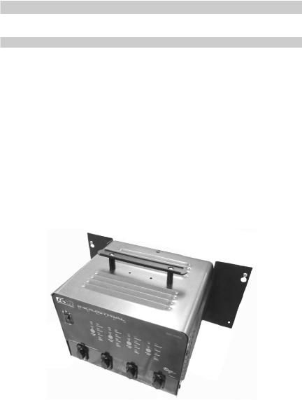
Models / Modelos / Modèles: INC-406A & INC-406AC Automatic Battery Charger / Cargador de batería automático / Chargeur de batterie automatique
Voltage / Tensión / Tension: 6, 12
Amperage / Amperaje / Ampérage: 6
•OWNER’S MANUAL
•Manual del usuario
•GUIDE D’UTILISATION
•READ THE ENTIRE MANUAL BEFORE USING THIS PRODUCT. FAILURE TO DO SO CAN RESULT IN SERIOUS INJURY OR DEATH.
•LEA EL MANUAL COMPLETO ANTES DE UTILIZAR ESTE PRODUCTO. CUALQUIER FALLA PODRÍA RESULTAR EN SERIAS LESIONES O PODRÍA SER MORTAL.
•LIRE ENTIÈREMENT LE GUIDE AVANTD’UTILISER CE PRODUIT. L’ÉCHEC DE FAIRE AINSI PEUT S’ENSUIVRE DANS LA BLESSURE SÉRIEUSE OU LA MORT.
00-99-000940/0110

Table of Contents
Section |
Page |
IMPORTANT SAFETY INSTRUCTIONS |
2 |
PERSONAL PRECAUTIONS |
2 |
PREPARING TO CHARGE |
3 |
CHARGER LOCATION |
4 |
DC CONNECTION PRECAUTIONS |
4 |
FOLLOW THESE STEPS WHEN BATTERY IS INSTALLED |
4 |
IN VEHICLE. |
|
FOLLOW THESE STEPS WHEN BATTERY IS OUTSIDE VEHICLE. 5 |
|
BATTERY CHARGING – AC CONNECTIONS |
5 |
ASSEMBLY INSTRUCTIONS |
6 |
Mounting Instructions |
6 |
CONTROL PANEL |
7 |
OPERATING INSTRUCTIONS |
7 |
CALCULATING CHARGE TIME |
8 |
MAINTENANCE INSTRUCTIONS |
9 |
STORAGE INSTRUCTIONS |
9 |
TROUBLESHOOTING |
9 |
REPLACEMENT PARTS |
10 |
BEFORE RETURNING FOR REPAIRS |
10 |
LIMITED WARRANTY |
11 |
|
|
ÍNDICE |
|
SECCIÓN |
PÀGINA |
INSTRUCCIONES IMPORTANTES DE SEGURIDAD |
13 |
PRECAUCIONES PERSONALES |
14 |
PREPARACIÓN PARA LA CARGA |
14 |
UBICACIÓN DEL CARGADOR |
15 |
PRECAUCIONES DE CONEXIÓN EN CC |
15 |
SIGA ESTOS PASOS CUANDO LA BATERÍA ESTÉ COLOCADA |
|
EN EL VEHÍCULO. |
16 |
SIGA ESTOS PASOS CUANDO LA BATERÍA SE ENCUENTRE |
16 |
FUERA DEL VEHÍCULO. |
|
CARGA DE BATERÍA, CONEXIONES DE CA |
17 |
INSTRUCCIONES DE MONTAJE |
17 |
INSTRCCIONES PARA EL MONTAJE |
18 |
PANEL DE CONTROL |
18 |
INSTRUCCIONES DE OPERACIÓN |
19 |
CÁLCULO DE TIEMPO DE CARGA |
20 |
INSTRUCCIONES DE MANTENIMIENTO |
21 |
INSTRUCCIONES DE ALMACENAJE |
21 |
LOCALIZACIÓN Y SOLUCIÓN DE PROBLEMAS |
21 |
REPUESTOS |
22 |
ANTES DE DEVOLVER A REPARACIONES |
22 |
GARANTÍA LIMITADA |
23 |
|
|
TABLE DES MATIÈRES |
|
Partie |
Page |
CONSIGNES DE SÉCURITÉ IMPORTANTES |
25 |
PRÉCAUTIONS PERSONNELLES |
25 |
PRÉPARATION POUR LE CHARGEMENT |
26 |
EMPLACEMENT DU CHARGEUR |
27 |
PRÉCAUTIONS SUR LA CONNEXION C.C. |
27 |
ÉTAPES À SUIVRE QUAND LA BATTERIE EST INSTALLÉE |
27 |
DANS UN VÉHICULE. |
|
ÉTAPES À SUIVRE QUAND LA BATTERIE EST INSTALLÉE |
28 |
HORS DU VÉHICULE. |
|
CHARGEMENT D’UNE BATTERIE – RACCORDEMENTS C.A. |
29 |
DIRECTIVES DE MONTAGE |
29 |
Instructions de montage |
29 |
PANNEAU DE CONTRÔLE |
30 |
CONSIGNES D’UTILISATION |
31 |
CALCUL DU TEMPS DE CHARGEMENT |
32 |
CONSIGNES D’ENTRETIEN |
32 |
DIRECTIVES D’ENTREPOSAGE |
33 |
TABLEAU DE DÉPANNAGE |
33 |
PIÈCES DE RECHANGE |
34 |
AVANT DE L’ENVOYER POUR RÉPARATION |
34 |
GARANTIE LIMITÉE |
35 |
IMPORTANT: READ AND SAVE THIS SAFETY AND INSTRUCTION MANUAL.
SAVE THESE INSTRUCTIONS – The INC-406A and INC-406AC offer a wide range of features to accommodate your needs. This manual will show you how to use your charger safely and effectively. Please read, understand and follow these instructions and precautions carefully, as this manual contains important safety and operating instructions. The safety messages used throughout this manual contain a signal word, a message and an icon.
The signal word indicates the level of the hazard in a situation.
Indicates an imminently hazardous situation which, if not avoided, will result in death or serious injury to the operator or bystanders.
Indicates a potentially hazardous situation which, if not avoided, could result in death or serious injury to the operator or bystanders.
Indicates a potentially hazardous situation which, if not avoided, could result in moderate or minor injury to the operator or bystanders.
Indicates a potentially hazardous situation which, if not avoided, could result in damage to the equipment or vehicle or property damage.
Safety messages in this manual contain two different type styles.
•Unnumbered type states the hazard.
•Numbered type states how to avoid the hazard.
The icon gives a graphical description of the potential hazard.
Pursuant to California Proposition 65, this product contains chemicals known to the State of California to cause cancer and birth defects or other reproductive harm.
• 1 •

1.IMPORTANT SAFETY INSTRUCTIONS
Risk of electric shock or fire.
1.1Do not expose the charger to rain or snow.
1.2Use only recommended attachments. Use of an attachment not recommended or sold by Schumacher® Electric Corporation may result in a risk of fire, electric shock or injury to persons or damage to property.
1.3To reduce the risk of damage to the electric plug or cord, pull by the plug rather than the cord when disconnecting the charger.
1.4An extension cord should not be used unless absolutely necessary. Use of an improper extension cord could result in a risk of fire and electric shock. If an extension cord must be used, make sure:
•That the pins on the plug of the extension cord are the same number, size and shape as those of the plug on the charger.
•That the extension cord is properly wired and in good electrical condition.
•That the wire size is large enough for the AC ampere rating of the charger as specified in Section 8.
1.5To reduce the risk of electric shock, unplug the charger from the outlet before attempting any maintenance or cleaning. Simply turning off the controls will not reduce this risk.
1.6Remove personal metal items such as rings, bracelets, necklaces and watches when working with a lead-acid battery. A lead-acid battery can produce a shortcircuit current high enough to weld a ring or the like to metal, causing a severe burn.
1.7Do not operate the charger with a damaged cord or plug; take it to a qualified service person. (Call customer service at: 1-800-621-5485.)
1.8Do not operate the charger if it has received a sharp blow, been dropped or otherwise damaged in any way; take it to a qualified service person. (Call customer service at: 1-800-621-5485.)
1.9Do not disassemble the charger; take it to a qualified service person when service or repair is required. Incorrect reassembly may result in a risk of fire or electric shock. (Call customer service at: 1-800-621-5485.)
2.PERSONAL PRECAUTIONS
Risk of explosive gases.
2.1Working in the vicinity of a lead-acid battery is dangerous. Batteries generate explosive gases during normal battery operation. For this reason, it is of utmost importance that you follow the instructions each time you use the charger.
2.2To reduce the risk of a battery explosion, follow these instructions and those published by the battery manufacturer and the manufacturer of any equipment you intend to use in the vicinity of the battery. Review the cautionary markings on these products and on the engine.
•2 •
2.3This charger employs parts, such as switches and circuit breakers, that tend to produce arcs and sparks. If used in a garage, locate this charger 18 inches or more above floor level.
2.4NEVER smoke or allow a spark or flame in the vicinity of a battery or engine.
2.5Be extra cautious to reduce the risk of dropping a metal tool onto the battery. It might spark or short-circuit the battery or other electrical part that may cause an explosion.
2.6Use this charger for charging LEAD-ACID batteries only. It is not intended to supply power to a low voltage electrical system other than in a starter-motor application. Do not use this battery charger for charging dry-cell batteries that are commonly used with home appliances. These batteries may burst and cause injury to persons and damage to property.
2.7NEVER charge a frozen battery.
2.8NEVER overcharge a battery.
3.PREPARING TO CHARGE
Risk of contact with battery acid. Battery acid is a highly corrosive sulfuric acid.
3.1Consider having someone close enough by to come to your aid when you work near a lead-acid battery.
3.2Have plenty of fresh water and soap nearby in case battery acid contacts your skin, clothing or eyes.
3.3Wear complete eye and body protection, including safety goggles and protective clothing. Avoid touching your eyes while working near the battery.
3.4If battery acid contacts your skin or clothing, immediately wash the area with soap and water. If acid enters your eye, immediately flood the eye with cold running water for at least 10 minutes and get medical attention right away.
3.5If it is necessary to remove the battery from the vehicle to charge it, always remove the grounded terminal first. Make sure all of the accessories in the vehicle are off to prevent arcing.
3.6Be sure the area around the battery is well ventilated while the battery is being charged.
3.7Clean the battery terminals before charging the battery. During cleaning, keep airborne corrosion from coming into contact with your eyes, nose and mouth. Use baking soda and water to neutralize the battery acid and help eliminate airborne corrosion. Do not touch your eyes, nose or mouth.
3.8Add distilled water to each cell until the battery acid reaches the level specified by the battery manufacturer. Do not overfill. For a battery without removable cell caps, such as valve regulated lead acid batteries (VRLA), carefully follow the manufacturer’s recharging instructions.
3.9Read, understand and follow all instructions for the charger, battery, vehicle and any equipment used near the battery and charger. Study all of the battery manufacturer’s specific precautions while charging and recommended rates of charge.
3.10Determine the voltage of the battery by referring to the vehicle owner’s manual and make sure that the output voltage selector switch is set to the correct voltage. If the charger has an adjustable charge rate, charge the battery in the lowest rate first.
•3 •
3.11Make sure that the charger cable clips make tight connections.
4.CHARGER LOCATION
Risk of explosion and contact with battery acid.
4.1Locate the charger as far away from the battery as the DC cables permit.
4.2Never place the charger directly above the battery being charged; gases from the battery will corrode and damage the charger.
4.3Do not set the battery on top of the charger.
4.4Never allow battery acid to drip onto the charger when reading the electrolyte specific gravity or filling the battery.
4.5Do not operate the charger in a closed-in area or restrict the ventilation in any way.
5.DC CONNECTION PRECAUTIONS
5.1Connect and disconnect the DC output clips only after setting all of the charger switches to the “off” position and removing the AC plug from the electrical outlet. Never allow the clips to touch each other.
5.2Attach the clips to the battery and chassis, as indicated in sections 6 and 7.
6.FOLLOW THESE STEPS WHEN BATTERY IS INSTALLED IN VEHICLE.
A spark near the battery may cause a battery explosion. To reduce the risk of a spark near the battery:
6.1Position the AC and DC cables to reduce the risk of damage by the hood, door and moving or hot engine parts. NOTE: If it is necessary to close the hood during the charging process, ensure that the hood does not touch the metal part of the battery clips or cut the insulation of the cables.
6.2Stay clear of fan blades, belts, pulleys and other parts that can cause injury.
6.3Check the polarity of the battery posts. The POSITIVE (POS, P, +) battery post usually has a larger diameter then the NEGATIVE (NEG, N, -) post.
6.4Determine which post of the battery is grounded (connected) to the chassis. If the negative post is grounded to the chassis (as in most vehicles), see step
6.5.If the positive post is grounded to the chassis, see step 6.6.
6.5For a negative-grounded vehicle, connect the POSITIVE (RED) clip from the battery charger to the POSITIVE (POS, P, +) ungrounded post of the battery. Connect the NEGATIVE (BLACK) clip to the vehicle chassis or engine block away from the battery. Do not connect the clip to the carburetor, fuel lines or sheet-metal body parts. Connect to a heavy gauge metal part of the frame or engine block.
•4 •
6.6For a positive-grounded vehicle, connect the NEGATIVE (BLACK) clip from the battery charger to the NEGATIVE (NEG, N, -) ungrounded post of the battery. Connect the POSITIVE (RED) clip to the vehicle chassis or engine block away from the battery. Do not connect the clip to the carburetor, fuel lines or sheetmetal body parts. Connect to a heavy gauge metal part of the frame or engine block.
6.7When disconnecting the charger, turn all switches to off, disconnect the AC cord, remove the clip from the vehicle chassis and then remove the clip from the battery terminal.
6.8See CALCULATING CHARGE TIME for length of charge information.
7.FOLLOW THESE STEPS WHEN BATTERY IS OUTSIDE VEHICLE.
A spark near the battery may cause a battery explosion. To reduce the risk of a spark near the battery:
7.1Check the polarity of the battery posts. The POSITIVE (POS, P, +) battery post usually has a larger diameter than the NEGATIVE (NEG, N, -) post.
7.2Attach at least a 24-inch (61 cm) long 6-gauge (AWG) insulated battery cable to the NEGATIVE (NEG, N, -) battery post.
7.3Connect the POSITIVE (RED) charger clip to the POSITIVE (POS, P, +) post of the battery.
7.4Position yourself and the free end of the cable you previously attached to the NEGATIVE (NEG, N, -) battery post as far away from the battery as possible – then connect the NEGATIVE (BLACK) charger clip to the free end of the cable.
7.5Do not face the battery when making the final connection.
7.6When disconnecting the charger, always do so in the reverse order of the connecting procedure and break the first connection while as far away from the battery as practical.
7.7A marine (boat) battery must be removed and charged on shore. To charge it onboard requires equipment specially designed for marine use.
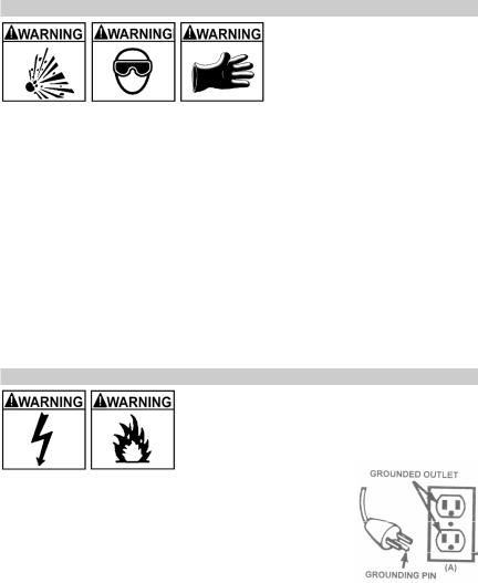
8.BATTERY CHARGING – AC CONNECTIONS
Risk of electric shock or fire.
8.1This battery charger is for use on a nominal 120-volt circuit and has a grounded plug that looks like the plug illustrated. The charger must be grounded to reduce the risk of electric shock. The plug must be plugged into an outlet that is properly installed and grounded in accordance with all local codes and ordinances. The plug pins must fit the receptacle (outlet). Do not use with an ungrounded system.
DANGER – Never alter AC cord or plug provided – if it does not fit the outlet, have proper grounded outlet installed by a qualified electrician. Improper connection can result in a risk of an electric shock or electrocution.
•5 •
NOTE: Pursuant to Canadian Regulations, use of an adapter plug is not allowed in Canada. Use of an adapter plug in the United States is not recommended.
8.2Recommended minimum AWG size for extension cord:
•100 feet long or less - use an 14 gauge extension cord.
•Over 100 feet long - use a 12 gauge extension cord.
9.ASSEMBLY INSTRUCTIONS
No assembly required
10.Mounting Instructions
To mount the charger to a wall or other flat surface:
10.1Remove the two screws from one side of the unit near the back.
10.2Attach a mounting bracket, with the keyhole towards the top, using the screws you just removed.
10.3Repeat for the other side. Note: Completely install one bracket before moving to the next.
10.4Using the charger as a template, install two #10 panhead screw anchors (or equivalent) into the wall you want to mount the charger to. Leave the heads of the screws extended 1/16” away from the surface. The mounting brackets are designed to match the 16” wall stud spacing commonly found in wood and steel framed buildings, for increased support install the anchors into the wall studs. NOTE: Make sure the screw/anchor combination installed into the wall is able to support up to fifty pounds of weight.
10.5Position the charger, with the mounting brackets installed, so that the keyhole slots on the mounting brackets line up with both screws you installed. Then slide the charger down so that the screw heads lock in the keyhole slot of the mounting brackets.
• 6 •
11.CONTROL PANEL
Illuminated ON/OFF Power Switch
Use this switch to turn the charger ON or OFF. When it is ON, it will light red.
LED Indicators
1.CONNECTED (red) LED - When lit, this LED indicates the battery is properly connected.
2.CHARGING (yellow) LED - When lit, this LED indicates the charger is charging the battery.
3.CHARGED (green) LED - When lit, this LED indicates the battery has reached full charge and the charger has gone into Maintain Mode.
4.CHECK BATTERY (red) LED - When flashing, this LED indicates there is a problem with the battery.
12.OPERATING INSTRUCTIONS
Charging
This charger is normally used when charging batteries out of a vehicle, but can also be used to charge a battery in a vehicle.
NOTE: This charger is equipped with an auto-start feature. It will not supply current to the battery clips until a battery is properly connected. Unlike traditional chargers, the clips will not spark if touched together.
1.Check to make sure every charger component is in place and in good working condition.
2.Connect the battery following the precautions listed in Sections 6 and 7.
3.Connect the battery cable to the charger.
4.Connect the AC power following the precautions listed in Section 8, if it is not already connected.
5.Turn the Main Power switch ON, if it is not already on.
6.Select the proper Battery Type, 6V or 12V.
The charger automatically starts charging and switches to Maintain Mode when complete.
Battery Connection Indicator
If the charger does not detect a properly connected battery, the CONNECTED (red) LED will not light until such a battery is detected. Charging will not begin until the CONNECTED (red) LED is on. When charging begins, the CHARGING (yellow) LED will illuminate.
Charging Mode
When an Automatic Charge is performed, the charger switches to the Maintain Mode (see below) automatically after the battery is charged.
• 7 •

Aborted Charge
If charging can not be completed normally, charging will abort. When charging aborts, the charger’s output is shut off, and the CHECK BATTERY (red) LED will blink. To reset after an aborted charge, disconnect the battery.
Desulfation Mode
If the battery is left discharged for an extended period of time, it could become sulfated and not accept a normal charge. If the charger detects a sulfated battery, the charger will switch to a special mode of operation designed for such batteries. If successful, normal charging will resume after the battery is desulfated. Desulfation could take up to 10 hours. If desulfation fails, charging will abort and the CHECK BATTERY (red) LED will blink, have the battery checked.
Completion of Charge
Charge completion is indicated by the CHARGED (green) LED. When lit, the charger has stopped charging and switched to the Maintain Mode of operation.
Maintain Mode
When the CHARGED (green) LED is lit, the charger has started Maintain Mode. In this mode, the charger keeps the battery fully charged by delivering a small current when necessary.
General Charging Notes
Fan: The charger is designed to control its cooling fan for efficient operation.
Consequentially, it is normal for the fan to start and stop when maintaining a fully charged battery. Keep the area near the charger clear of obstructions to allow the fan to operate efficiently.
13.CALCULATING CHARGE TIME
Use the following table to more accurately determine the time it will take to bring a battery to full charge. First, identify where your battery fits into the chart.
Find your battery’s rating on the chart below, and note the charge time given for each charger setting. The times given are for batteries with a 50% charge prior to recharging. Add more time for severely discharged batteries.
BATTERY SIZE/RATING |
|
CHARGE RATE/ |
||
|
|
|
|
CHARGING TIME |
|
|
|
|
6 AMP |
SMALL |
Motorcycle, |
|
6 - 12 AH |
38 min - 1¼ hrs |
BATTERIES |
garden |
|
|
|
|
12 - 32 AH |
1¼ - 3½ hrs |
||
|
tractor, etc. |
|
||
|
|
|
|
|
|
|
|
|
|
CARS/TRUCKS |
200 - 315 CCA |
|
40 - 60 RC |
3¾ - 4¾ hrs |
|
315 - 550 CCA |
|
60 - 85 RC |
4¾ - 6 hrs |
|
550 - 1000 CCA |
|
80 - 190 |
6 - 11½ hrs |
|
|
|
RC |
|
MARINE/DEEP CYCLE |
|
80 RC |
6 hrs |
|
|
|
|
140 RC |
9 hrs |
|
|
|
160 RC |
10 hrs |
|
|
|
180 RC |
11 hrs |
• 8 •
 Loading...