


MODEL SW
THIS MANUAL CONTAINS THE OPERATING INSTRUCTIONS AND SAFETY INFORMATION FOR YOUR SCAG MOWER. READING THIS MANUAL CAN PROVIDE YOU WITH ASSISTANCE IN MAINTENANCE AND ADJUSTMENT PROCEDURES TO KEEP YOUR MOWER PERFORMING TO MAXIMUM EFFICIENCY. THE SPECIFIC MODELS THAT THIS BOOK COVERS ARE CONTAINED ON THE INSIDE COVER. BEFORE OPERATING YOUR MACHINE, PLEASE READ ALL THE INFORMATION ENCLOSED.
MANUAL OPERATOR’S
© 2004 |
PART NO. 03145 |
SCAG POWER EQUIPMENT |
PRINTED 7/04 |
DIVISION OF METALCRAFT OF MAYVILLE, INC. |
PRINTED IN USA |

 WARNING:
FAILURE TO FOLLOW SAFE OPERATING PRACTICES
MAY RESULT IN SERIOUS INJURY.
*Keep all shields in place, especially the grass discharge chute.
*Before performing any maintenance or service, stop the machine and remove the spark plug wire and ignition key.
*If a mechanism becomes clogged, stop the engine before cleaning.
*Keep hands, feet and clothing away from power-driven parts.
*Read this manual completely as well as other manuals that came with your mower.
*Keep others off the tractor (only one person at a time)
REMEMBER - YOUR MOWER IS ONLY AS SAFE AS THE OPERATOR!
Hazard control and accident prevention are dependent upon the awareness, concern, prudence, and proper training of the personnel involved in the operation, transport, maintenance, and storage of the equipment.
This manual covers the operating instructions and illustrated parts list for:
SW32-15KA SW36A-15KA SW36A-15KH SW48A-15KA SW48A-15KH SW48A-17KA SW52A-17KA SW52A-18HN SW52A-18KH
with a serial number of A0100001 to A0199999 with a serial number of A0300001 to A0399999 with a serial number of A0400001 to A0499999 with a serial number of A0500001 to A0599999 with a serial number of A0600001 to A0699999 with a serial number of A0800001 to A0899999 with a serial number of A1000001 to A1099999 with a serial number of A1100001 to A1199999 with a serial number of A1200001 to A1299999
Always use the entire serial number listed on the serial number tag when referring to this product.

TABLE OF CONTENTS |
|
MODEL SW |
|
SUBJECT |
PAGE |
Introduction .................................................................................................. |
1 |
Direction Reference ..................................................................................... |
1 |
Servicing the Engine ................................................................................... |
1 |
Symbols ....................................................................................................... |
2-3 |
General Safety Instructions .......................................................................... |
4 |
Signal Words ............................................................................................... |
4 |
Before Operating Considerations ................................................................ |
4-6 |
Operation Considerations ............................................................................ |
6-7 |
Maintenance and Storage ........................................................................... |
7-8 |
Initial Run-In Procedures ............................................................................. |
8 |
Mower Operation ......................................................................................... |
8-9 |
Cutter Deck Belt Adjustments ...................................................................... |
9 |
Transmission Drive Belt ............................................................................... |
10 |
Drive Control Adjustments ........................................................................... |
10 |
Cutter Deck Adjustments ............................................................................. |
10-11 |
Blade Height Adjustments ........................................................................... |
11 |
Cutter Blades ............................................................................................... |
11 |
Custom-Cut Baffle Adjustment..................................................................... |
12 |
Engine Oil Maintenance .............................................................................. |
13 |
Engine Air Cleaner Maintenance................................................................. |
13 |
Cleaning The Machine ................................................................................ |
13 |
Lubrication and Maintenance Chart ............................................................ |
14 |
Troubleshooting Cutting Conditions ............................................................ |
15-17 |
Technical Specifications .............................................................................. |
18-19 |
WE SUPPORT OPE
TECHNICIAN
CERTIFICATION
I

TABLE OF CONTENTS |
|
(CONTINUED) |
|
SUBJECT |
PAGE |
Illustrated Parts List |
|
SWM-32", 36" Cutter Deck .......................................................................... |
20-21 |
SWM-48", 52" Cutter Deck .......................................................................... |
22-23 |
Notes .......................................................................................................... |
24 |
Caster Assembly ......................................................................................... |
25 |
Engine Deck - 15KH, 18KH, 15KA, 17KA, 18HN ........................................ |
26-27 |
Handle Assembly ........................................................................................ |
28-29 |
Instrument Panel .......................................................................................... |
30 |
Peerless Transmission ................................................................................. |
31 |
Engine Deck Wire Harness ......................................................................... |
32 |
Handle Wire Harness .................................................................................. |
32 |
Wire Harness Adapter-Honda (18 HP) ........................................................ |
33 |
Wire Harness Adapter-Kawasaki (15 HP & 17 HP) ..................................... |
33 |
Replacement Decals ................................................................................... |
34-35 |
Warranty Statement ......................................................................... |
Inside Back Cover |
II

GENERAL INFORMATION
INTRODUCTION
Your mower was built to the highest standards in the industry. However, the prolonged life and maximum efficiency of your mower depends on you following the operating, maintenance and adjustment instructions in this manual.
If additional information or service is needed, contact your Scag Power Equipment Dealer.
We encourage you to contact your dealer for repairs. All Scag dealers are informed of the latest methods to service this equipment and provide prompt and efficient service in the field or at their service shop. They carry a full line of Scag service parts.
USE OF OTHER THAN ORIGINAL SCAG REPLACEMENT PARTS WILL VOID THE WARRANTY.
For pictorial clarity, some illustrations and figures in this manual may show shields, guards or plates open or removed. Under no circumstances should your mower be operated without these devices in place.
All information is based upon product information available at the time of approval for printing. Scag Power Equipment reserves the right to make changes at any time without notice and without incurring any obligation.
 WARNING
FALLING HAZARD
USE ONLY SCAG APPROVED
RIDING ATTACHMENTS
SEE OPERATOR'S MANUAL 481109
USE ONLY SCAG APPROVED ATTACHMENTS AND ACCESSORIES.
Attachments and accessories manufactured by companies other than Scag Power Equipment are not approved for use on this machine. Using unapproved attachments, (especially "stand-up" riding attachments) may be hazardous.
SCAG APPROVED ATTACHMENTS AND ACCESSORIES:
GC-F4 (p/n 9002)
GC-4D (p/n 9001)
Mulch Plate (p/n 9258, 9259, 9260, 9261)
Hurricane Mulch System (p/n 9263, 9264, 9265, 9266)
Cup Holder (p/n 9240)
Hour Meter (p/n 48023)
Turbo Baffle (p/n 423955, 423956, 423957)
Blade Buddy (p/n 9212)
Flat-Free Caster Tires (p/n 9275)
DIRECTION REFERENCE
The “Right” and “Left”, “Front” and “Rear” of the machine are referenced from the operator’s right and left when standing in the normal operating position and facing the forward travel direction.
SERVICING THE ENGINE
The detailed servicing and repair of the engine is not covered in this manual; only routine maintenance and general service instructions are provided. For service of the engine during the limited warranty period, it is important to contact your Scag dealer or find a local authorized servicing agent of the engine manufacturer. Any unauthorized work done on the engine during the warranty period may void your warranty.
1
ISO Symbols |
CE Mark |
SYMBOL |
DESCRIPTION |
SYMBOL |
DESCRIPTION |
|
|
|
|
|
Choke |
|
Transmission |
Parking Brake |
Spinning Blade |
|
48071S |
|
|
|
|
On/Start |
|
Spring Tension on Idler |
|
||
|
||
Off/Stop |
Oil |
 WARNINGFalling Hazard
FALLING HAZARD
USE ONLY SCAG APPROVED
RIDING ATTACHMENTS
SEE OPERATOR'S MANUAL 481109
2
SYMBOL |
DESCRIPTION |
SYMBOL |
DESCRIPTION |
|
|
|
|
|
Fast |
|
Slow |
Continuously Variable - Linear |
Cutting Element - Basic Symbol |
|
Pinch Point |
Cutting Element - Engage |
481039S
Hourmeter/Elapsed Operating Hours |
Cutting Element - Disengage |
Thrown Object Hazard |
Read Operator's Manual |
Keep Bystanders Away |
|
3
SAFETY INFORMATION
GENERAL SAFETY INFORMATION
Your mower is only as safe as the operator. Carelessness or operator error may result in serious bodily injury or death. Hazard control and accident prevention are dependent upon the awareness, concern, prudence, and proper training of the personnel involved in the operation, transport, maintenance and storage of the equipment. Make sure every operator is properly trained and thoroughly familiar with all of the controls before operating the mower. The owner/user can prevent and is responsible for accidents or injuries occurring to themselves, other people or property.
READ THIS OPERATOR’S MANUAL BEFORE ATTEMPTING TO START YOUR MOWER.
If the operator(s) or mechanic(s) cannot read English or Spanish, it is the owner's responsibility to explain this material to them.
A replacement manual is available from your authorized Scag Service Dealer or by contacting Scag Power Equipment, Service Department at P.O. Box 152, Mayville, WI 53050 or contact us via the Internet at www.scag.com. The manual for your machine can be downloaded by using the model and serial number or use the contact form to make your request. Please indicate the complete model and serial number of your Scag product when requesting replacement manuals.
SIGNAL WORDS
This symbol means “Attention! Become Alert! Your Safety is Involved!" The symbol is used with the following signal words to attract your attention to safety messages found on the decals on the machine and throughout this manual. The message that follows the symbol contains important information about safety. To avoid injury and possible death, carefully read the message! Be sure to fully understand the causes of possible injury or death.
Signal Word:
The signal word is a distinctive word found on the safety decals on the machine and throughout this manual that alerts the viewer to the existence and relative degree of the hazard.
The signal word “DANGER” denotes that an extremely hazardous situation exists on or near the machine that could result in high probability of death or irreparable injury if proper precautions are not taken.
 WARNING:
The signal word “WARNING” denotes that a hazard exists on or near the machine that can result in injury or death if proper precautions are not taken.
 CAUTION:
The signal word “CAUTION” is a reminder of safety practices on or near the machine that could result in personal injury if proper precautions are not taken.
Your safety and the safety of others depends significantly upon your knowledge and understanding of all correct operating practices and procedures of this machine.
BEFORE OPERATION
CONSIDERATIONS
1.Become familiar with the safe operation of the equipment, operator controls, and safety signs.
2.NEVER allow children or untrained people to operate or service this machine.
3.Clear the area to be mowed of objects that could be picked up and thrown by the cutter blades.
4

BEFORE OPERATION CONSIDERATIONS (CONT'D)
4.Always wear appropriate clothing, loose fitting clothing, long hair or jewelry could get tangled in moving parts. Do not operate the machine wearing shorts; always wear adequate protective clothing including long pants. Wearing safety glasses, safety shoes and a helmet is advisable and is required by some local ordinances and insurance regulations.
5.Operator hearing protection is recommended, particularly for continuous operation of the mower. Wear suitable hearing protection. Prolonged exposure to loud noise can cause hearing impairment or hearing loss.
6.Keep the machine and attachments in good operating condition. Keep all shields and safety devices in place. If a shield, safety device or decal is defective or damaged, repair or replace it before operating the machine.
 WARNING:
This machine is equipped with an interlock system intended to protect the operator and others from injury. This is accomplished by preventing the engine from starting unless the deck drive is disengaged, the transmission is in neutral, and the neutral latches are in the neutral position. The system shuts off the engine if the operator releases the operator presence levers with the deck drive engaged and/or the transmission not in neutral. Never operate equipment with the interlock system disconnected or malfunctioning.
7.Fill the fuel tank with clean, fresh gasoline, with a minimum octane rating of 87. To avoid personal injury or property damage, use extreme care in handling gasoline. Gasoline is extremely flammable and the vapors are explosive.
A. Extinguish all cigarettes, cigars, pipes and other sources of ignition.
B. Use only an approved gasoline container.
C.Never remove the gas cap or add fuel with the engine running. Allow the engine to cool before fueling.
D.Never fuel the machine indoors or in an enclosed trailer.
E.Never store the machine or fuel container where there is an open flame, spark or pilot light such as on a water heater or other appliances.
F.Never fill containers inside a vehicle or on a truck or trailer bed with a plastic liner. Always place containers on the ground away from your vehicle before filling.
G.Remove the machine from the truck or trailer and fuel on the ground. If this is not possible, then refuel the machine with a portable container, rather than from a gasoline dispenser nozzle.
H.Keep the nozzle in contact with the rim of fuel tank or container opening at all times until fueling is complete. Do not use a nozzle lock-open device.
I.If fuel is spilled on clothing, change clothing immediately
J.Replace gas cap and tighten securely.
8.Before attempting to start the engine, shift the transmission into neutral, move the blade engagement switch to the OFF position, and move the neutral latches to neutral.
 WARNING
DO NOT OPERATE WITHOUT DISCHARGE CHUTE, MULCHING
KIT, OR ENTIRE GRASS CATCHER INSTALLED
9.The discharge chute must always be installed and in the down position on the side discharge cutter deck except when the Scag optional grass catcher or mulching plate are properly installed.
5

BEFORE OPERATION CONSIDERATIONS (CONT'D)
ROTATING BLADES
NEVER PUTYOUR HANDS INTOTHE DISCHARGE CHUTE FOR ANY REASON! Shut off the engine and remove the key and only then use a stick or similar object to remove material if clogging has occurred.
10.If the mower discharge ever plugs, shut off the engine, remove the ignition key, and wait for all movement to stop before removing the obstruction. Do not use your hand to dislodge the clogged discharge chute. Use a stick or other device to remove clogged material.
11.Check the blade mounting bolts at frequent intervals for proper tightness.
6.Using the machine demands attention. To prevent loss of control:
A.Mow only in daylight or when there is good artificial light.
B.Be alert for holes, rocks, roots and other hidden hazards in the terrain. Keep away from any dropoff. Beware of overhead obstructions (low limbs, etc), underground obstacles (sprinklers, pipes, tree roots, etc.). Cautiously enter a new area. Be alert for hidden hazards.
C.Do not drive close to a drop-off, ditch, creek bank, or other hazard.
D.Reduce speed and exercise extreme caution on slopes and in sharp turns to prevent tipping or loss of control. Be especially cautious when changing directions on slopes.
E.Always be sure of your footing. Keep a firm hold on the handles and walk---never run.
F.Do not operate where conditions are slippery
OPERATION CONSIDERATIONS
1.Before operating the mower, familiarize yourself with all mower and engine controls. Knowing the location, function and operation of these controls is important for safe and efficient operation of the mower.
2.Start the engine when the neutral latches are in the neutral lock position, the cutter blades are disengaged, and the transmission is in neutral.
3.Be sure the interlock switches are functioning correctly.
4.DO NOT mow when children and/or others are present. Keep children out of the mowing area and in the watchful care of a responsible adult other than the operator. Be alert and turn the machine off if a child enters the area.
5.DO NOT carry passengers.
 WARNING:
DO NOT operate on steep slopes. To check a slope, attempt to back up it (with the cutter deck down). If the machine can back up the slope without the wheels slipping, reduce speed and use extreme caution. ALWAYS FOLLOW OSHA APPROVED OPERATION.
7.Disengage power to the cutter deck before backing up. Do not mow in reverse unless absolutely necessary and then only after observation of the entire area behind the mower.
8.Disengage power to the cutter deck before crossing roads, walks or gravel drives. Stop blades if not mowing.
9.Shut the engine off and wait until the blades come to a complete stop before removing the grass catcher container.
10.Never raise the cutter deck while the blades are rotating.
6
OPERATION CONSIDERATIONS (CONT'D)
ROTATING BLADES
NEVER PUTYOUR HANDS INTO THE DISCHARGE CHUTE FOR ANY REASON!
11.Keep hands and feet away from cutter blades and moving parts. Contact can injure.
12.DO NOT operate without the side discharge chute installed and in the down position.
13.DO NOT direct the discharge of material toward bystanders or allow anyone near the machine while in operation.
14.If the cutting blades should strike a solid object or the equipment should start to vibrate abnormally, stop the engine, disconnect the spark plug wire, and check immediately for the cause. Vibration is generally a warning of trouble. Check the machine for damaged or defective parts. Repair any damage before starting the engine or operating the cutter deck. Be sure the blades are in good condition and the blade bolts are tight.
15.Take all possible precautions when leaving the machine unattended, such as disengaging the mower, stopping the engine, and removing the key.
 CAUTION:
DO NOT touch the engine or the muffler while the engine is running or immediately after stopping. These areas may be hot enough to cause a burn.
 WARNING:
DO NOT run the engine inside a building or a confined area without proper ventilation. Exhaust fumes are hazardous and could cause death.
16.DO NOT operate the machine under the influence of alcohol or drugs.
17.Use care when loading or unloading the machine onto a truck or trailer.
18.Use care when approaching blind corners, shrubs, trees, or other objects that may obscure vision.
19.Do not change the engine governor settings or overspeed the engine. See the engine operator's manual for information on engine settings.
MAINTENANCE AND STORAGE
1.Allow only trained personnel to service the machine.
2.Park the machine on level ground.
3.Never make adjustments to the machine with the engine running unless specifically instructed to do so. If the engine is running, keep hands, feet, and clothing away from moving parts.
4.Disengage drives, lower implement, stop engine and remove key or disconnect spark plug wire(s) to prevent accidental starting of the engine when servicing or adjusting the machine. Wait for all movement to stop before adjusting, cleaning or repairing.
5.If the mower must be tipped to perform maintenance or adjustment, remove the battery, drain the gasoline from the fuel tank and the oil from the crankcase.
6.Keep all nuts, bolts and screws tight, to ensure the machine is in safe working condition. Check the blade mounting bolts frequently to be sure they are tight. Replace all worn or damaged decals.
7.Clean grass and debris from cutting units, drives, mufflers, and engine to help prevent fires. Clean up oil or fuel spillage.
8.The engine must be shut off before checking the oil or adding oil to the crankcase.
7

MAINTENANCE AND STORAGE (CONT'D)
9. Let the engine cool before storing.
10.DO NOT store the machine near an open flame.
11.Shut off fuel while storing or transporting.
12.Always store gasoline in a safety-approved, red container.
13.Use jack stands to support components when required.
14.Carefully release pressure from components with stored energy.
15.Use care when checking blades. Wrap the blade(s) or wear gloves and use caution when servicing blades. Only replace blades. NEVER straighten or weld blades.
INITIAL RUN-IN PROCEDURES (FIRST DAY OF USE OR APPROXIMATELY 10 HOURS)
1.Check the belts for proper tension at 2, 4 and 8 hours. Adjust as needed.
2.Check the steering control rods for neutral adjust ment (See Adjustments, page 10).
3.Check the tires for proper pressure.
Caster Wheels |
25 psi. |
Drive Wheels |
12 psi. |
4.Check for loose hardware. Tighten as needed.
5.Check the safety switches for proper adjustment:
*The engine will not start if the PTO switch is on.
*The engine will not start if the machine is not in neutral.
*The engine should start if the machine is in neutral and the PTO engagement switch is off.
6.Apply lubricant to all the grease fittings. Lubricant was applied at the factory. This is just a precautionary check to make sure that all the fittings have been lubricated.
MOWER OPERATION
1.Read and understand the safety instructions before attempting to operate this machine.
2.Before starting the engine:
*Check the oil level in the engine.
*Fill the fuel tank with clean, fresh, lead-free gasoline.
*Open the fuel valve on the bottom of the fuel tank.
-NOTE-
Use gasoline with an octane rating no less than
87.
*The transmission must be in NEUTRAL.
*The blade clutch switch must be in the OFF position.
*The operator's presence levers must be released.
*The neutral latches must be in the neutral lock position
*The key switch must be on.
3.Start the engine:
*Choke as required. If the engine is cold, pull the choke knob out. When the engine starts, slowly push the choke in. If the engine stalls, repeat the above operation. When the engine is warm, choking may not be necessary.
4.Engage the cutter blades by depressing the operator presence levers and pulling the blade clutch switch into the ON position. Push the switch to the OFF position to disengage the cutter blades.
8
MOWER OPERATION (CONT'D)
PULL UP TO ENGAGE
PUSH DOWN TO DISENGAGE
390S0138
-NOTE-
When PTO is engaged or (possibly) disengaged, a squealing sound from the underside of the machine is normal. It is caused by the electric clutch plates meshing as the mower comes up to speed. For best equipment life, engage the clutch with the engine at 3/4 throttle, not under full load.
 WARNING:
To avoid serious bodily injury and damage to the transmission, the machine must be at a full stop before shifting between gears or shifting between forward and reverse.
5.Shift the transmission into gear for the desired mowing speed.
-NOTE-
Top speed is suggested only for transport!
6.While squeezing the steering brake levers with both hands, release both neutral latches.
7.When the steering brake levers are released, the machine will travel straight. To make a right turn, squeeze the RH lever. To turn left, squeeze the LH lever.
8.TO STOP, squeeze both levers, lock the neutral latches, and shift the transmission into neutral.
CUTTER DECK BELT ADJUSTMENTS
 CAUTION:
Stop engine and remove the key from the ignition before making any adjustments. Wait for all moving parts to come to a complete stop before beginning work.
1.Remove the belt cover.
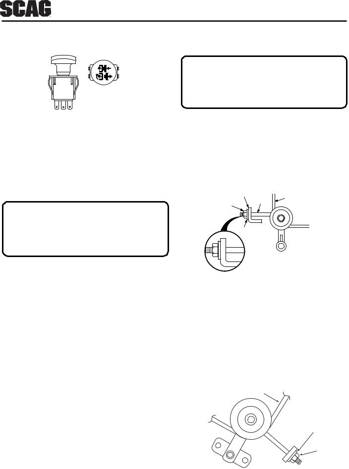
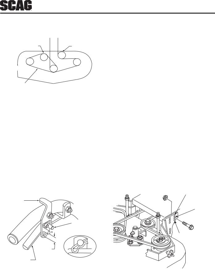
2.Adjust the cutter deck drive belt using a belt tension gauge. Adjust the belt so that the belt moves 1/2" with 10 pounds of pressure. Adjust the tension by tightening or loosening the J-bolt nut. ( See figure 1).
END OF L-SHAPED
BRACKET
BELT
"J" BOLT
NUT
WASHER
CUTTER DECK DRIVE BELT TENSION |
|
ALIGNMENT IDLER - L.H. |
SC400G |
Figure 1. Deck Drive Belt Adjustment
-NOTE-
Due to initial belt stretch and to prevent the belt from slipping, check this adjustment after the first 2 hours, 4 hours and 8 hours of operation.
3.Adjust the RH blade drive belt using a belt tension gauge. Adjust the belt so that the belt moves 1/2" with 10 pounds of pressure. Adjust the tension by tightening or loosening the J-bolt nut. (See Figure 2
& 3). |
BELT |
WASHER
NUT
SC401G
Figure 2. Cutter Deck Belt Adjustment R.H.
9
CUTTER DECK BELT ADJUSTMENTS (CONT'D)
BELT TENSION |
CUTTER DECK |
ADJUSTMENT IDLER |
ADJUSTMENT |
|
IDLER |
DISCHARGE
AREA
CHECK BLADE DRIVE |
SC402G |
|
|
BELT TENSION HERE |
|
Figure 3. Cutter Deck Belt
4. Replace the belt cover.
TRANSMISSION DRIVE BELT
Adjust the transmission drive belt so that there is about a 3/16" deflection with 10 lbs. of pressure. Adjust by loosening idler pulley mounting bolt and sliding the idler left or right to change belt tension.
DRIVE CONTROL ADJUSTMENTS
1.Adjust the steering control rods so that there is approximately 3/4" clearance from the bottom of the rod to the bottom of the neutral latch slot when in the
drive position. (See Figure 4)
Neutral
Latch
Neutral Lock
Position
 Drive Position
3/4"
Steering
Brake Lever
SC404GB05
-NOTE-
Operator presence lever removed for clarity.
Never operate equipment with the interlock system disconnected.
Figure 4. Steering Control Rod Adjustment
2.Adjust the steering brake rods so that the brakes do not apply until the steering levers are pulled tight to the handles. When the steering levers are locked in the neutral position the machine should move freely.
CUTTER DECK ADJUSTMENTS
Due to the many cutting conditions that exist, it is difficult to suggest a cutter deck setting that will work for every lawn. There are two adjustments that can be made on these decks, pitch and height.
PITCH is the angle of the blades (comparing front to rear). A 1/4" downward pitch (front of deck down) is recommended for best cutting performance.
HEIGHT is the nominal distance the blade is off of the ground. This measurement is made with the blades pointed side to side and distance is measured between cutting tip and ground. (Also see Blade Height Adjustment, next page).
Changes to the cutting height can be achieved by repositioning the cutter deck. (This adjustment will also effect the pitch of the deck). There are three available positions (See Figure 5).
LOW CUT (1 3/4" to 3")
MID RANGE (2 1/2" to 3 3/4")
HIGH CUT
(3 1/4" to 4 1/2")
SC405G-2
Figure 5. Cutting Height Adjustment
10

CUTTER DECK ADJUSTMENTS (CONT'D)
Caster spacers also can be repositioned to change cutting heights and to change the pitch of the deck. (See Figure 6).
Pin
 Spacers
2002SGB005
Figure 6. Caster Wheel Spacers
BLADE HEIGHT ADJUSTMENT
Adjusting the blade height can be done by moving any number of the five smaller 1/4" spacers on the blade mounting bolts to the top of the spindle shaft or below the spindle shaft.
-NOTE-
All blades should be positioned equally.
For best cut and discharge, a minimum of three spacers should be installed between the blade and the spindle (See Figure 7).
 WARNING:
Blades have a sharp cutting edge. Wear proper eye protection and protective gloves or wrap blades with protective material when removing, sharpening and installing blades.
2002 SC407G
Figure 7. Blade Spacers
CUTTER BLADES
Do not sharpen beyond 1/3 of the width of the blade. (See Figure 8).
-NOTE-
Dress the blade with a file. Using a wheel grinder may burn the blade. Check the balance of the blade. If blades are out of balance, vibration and premature wear of spindle assembly can occur. See your authorized Scag dealer for blade balancing or special tools, if you choose to balance your own blades.
Angle Blade Back
Do Not Cut In
X
|
X Must NOT Exceed |
|
30 |
1/3 Blade Width |
|
SGB033 |
||
|
Figure 8. Blade Sharpening
11
CUSTOM-CUT BAFFLE ADJUSTMENT
The Custom-Cut Baffle is designed to deliver optimum airflow and superior cutting performance in any type of grass. The Custom-Cut Baffle can be raised or lowered to precisely tailor the deck's performance for the type of grass being cut. The baffle can be set in three (3) different positions for optimum performance.
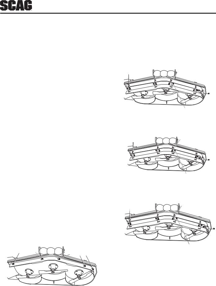
A.3" Position - baffle is installed using the top set of holes on the front baffle welded inside the cutter deck. (See Figure 10). The Advantage cutter deck will deliver the best quality-of-cut in very tall, wiry, tough to cut grass.
B.3-1/2" Position (factory setting) - baffle is installed using the middle set of holes on the front baffle welded inside the cutter deck. (See Figure 11). For general purpose cutting, place the Custom Cut Baffle in the 3-1/2" position. This gives the best mix of cutting performance in all types of grass.
C.4" Position - baffle is installed using the bottom set of holes on the front baffle welded inside the cutter deck. (See Figure 12). Placing the baffle in the 4" setting will enhance fall cutting (leaf pickup) and reduce cutter deck "blowout".
TO ADJUST THE CUSTOM-CUT BAFFLE HEIGHT:
1.Remove the hardware securing the Custom-Cut Baffle to the cutter deck (See Figure 9).
-NOTE-
Hardware location used in the illustrations are for reference only. Location of hardware may vary depending on the cutter deck size.
2.Move the Custom-Cut Baffle to desired position. (See Figures 10 through 12 for position)
3.Reinstall the mounting hardware as shown. (See Figures 10 though 12). Torque hardware to 39ft.lbs.
TOP SET OF HOLES |
CARRIAGE BOLT |
|
FOR 3" SETTING |
||
|
2004 CCB - 3" Setting
ELASTIC STOP
NUT
Figure 10. 3" Custom-Cut Baffle Position
MIDDLE SET OF HOLES |
CARRIAGE BOLT |
|
FOR 3-1/2" SETTING |
||
|
2004 CCB - 3-1/2" Setting
ELASTIC STOP
NUT
Figure 11. 3-1/2" Custom-Cut Baffle Position
BOTTOM SET OF HOLES |
CARRIAGE BOLT |
|
FOR 4" SETTING |
||
|
2004 CCB - 4" Setting
MOUNTING |
MOUNTING |
ELASTIC STOP |
|
HARDWARE |
NUT |
||
HARDWARE |
|||
|
|
Figure 12. 4" Custom-Cut Baffle Position
2004 CCB
Figure 9. Custom-Cut Baffle
12

CHECKING ENGINE CRANKCASE OIL LEVEL
The engine oil level should be checked after every 8 hours of operation or daily as instructed in the Engine Operator’s Manual furnished with this mower.
CHANGING ENGINE CRANKCASE OIL
After the first 5 hours of operation, change the engine crankcase oil and replace the oil filter. Thereafter, change the engine crankcase oil after every 100 hours of operation or bi-weekly, whichever occurs first. Refer to the Engine Operator’s Manual furnished with this mower for instructions.
CHANGING ENGINE OIL FILTER
After the first 5 hours of operation, replace the engine oil filter. Thereafter, replace the oil filter every 200 hours of operation or every month, whichever occurs first. Refer to Engine Operator’s Manual for instructions.
ENGINE AIR CLEANER
For any air cleaner, the operating environment dictates how often the air cleaner should be serviced. Refer to the Engine Operator’s Manual furnished with this mower for instructions.
-NOTE-
In extremely dusty conditions it may be necessary to service the air cleaner daily to prevent engine damage.
CLEANING THE MACHINE
 CAUTION:
Do not wash any portion of the equipment while it is hot. Do not wash the engine; use compressed air.
1.After each use, wash the mower and cutter deck. Use cold water and automotive cleaners. Do not use pressure cleaners.
2.Do not spray electrical components.
3.Repair damaged metal surfaces using Scag touch-up paint (P/N 48521) available from your authorized Scag dealer. Wax the mower with an automotive paint wax for maximum paint protection.
13

LUBRICATION & MAINTENANCE
BREAK-IN |
|
|
|
|
+ Grease spindle until grease comes out the relief valve. |
||||||||
|
|
|
|
|
|
|
|
|
|
|
|
|
|
|
8 HOURS (DAILY) |
|
|
CompatibleGreases: |
Lidok EP #2 (found at industrial shops) |
||||||||
|
|
|
|
|
|
|
|
|
|||||
|
|
40 HOURS (WEEKLY) |
|
|
|
|
Ronex MP (Exxon service stations) |
||||||
|
|
|
|
|
|
ShellAlvania(Shellservicestations) |
|||||||
|
|
|
|
|
|
|
|
|
|
|
|
||
|
|
|
|
|
|
|
|
|
|
|
|
||
|
|
|
100 HOURS (BIWEEKLY) |
|
|
Mobilux #2 (Mobil service stations) |
|||||||
|
|
|
|
500 HRS OR ANNUALLY |
|
|
Super Lub M EP #2 (Conoco service stations) |
||||||
|
|
|
|
|
|
|
|
||||||
|
|
|
|
|
|
|
|
|
|
|
|
|
|
|
|
|
|
|
|
|
|
|
|
PROCEDURE |
|
COMMENTS |
|
X |
|
|
|
|
|
Check all hardware for |
proper tightness |
|
|
||||
X |
|
|
|
|
|
Change engine oil and |
filter at 5 hours |
|
|
||||
|
X |
|
|
|
|
Check engine oil |
|
|
|
|
Do not over fill |
||
|
X |
|
|
|
|
Remove debris from |
under belt cover |
|
More often if needed |
||||
|
X |
|
|
|
|
Sharpen cutter blades |
|
|
|
More often if needed |
|||
|
X |
|
|
|
|
Grease spindle bearings |
|
|
|
+ US Lithium MP White Grease 2125 |
|||
|
X |
|
|
|
|
Clean air filter |
|
|
|
|
More often if needed |
||
|
X |
|
|
|
|
Check belt tension |
|
|
|
|
|||
|
X |
|
|
|
|
Check tire pressure |
|
|
|
Add or adjust as required |
|||
|
|
X |
|
|
|
Change engine oil |
|
|
|
|
See engine mfg. information |
||
|
|
|
X |
|
|
|
|
|
|
|
|
|
|
|
|
|
|
Replace air filter |
|
|
|
|
More often if needed |
||||
|
|
|
X |
|
Grease caster wheel |
bearings |
|
Chassis grease |
|||||
|
|
|
X |
|
Grease caster wheel pivot shafts |
|
Chassis grease |
||||||
|
|
|
X |
|
Grease idler pulley bracket on cutter deck |
|
Chassis grease |
||||||
|
|
|
X |
|
Grease drive wheel bearings |
|
Chassis grease |
||||||
|
|
|
X |
|
Grease transmission couplers |
|
Chassis grease |
||||||
|
|
|
X |
|
Grease idler bracket LH & RH |
|
Chassis grease |
||||||
|
|
|
X |
|
Check all hardware for proper tightness |
|
More often if needed |
||||||
|
|
|
|
X |
Adjust air gap on electric clutch |
|
Contact your Scag dealer for information about |
||||||
|
|
|
|
|
|
|
|
|
|
|
|
|
making this adjustment |
|
|
|
|
|
|
|
|
|
|
|
|
|
|
14
TROUBLESHOOTING CUTTING CONDITIONS
CONDITION |
CAUSE |
CURE |
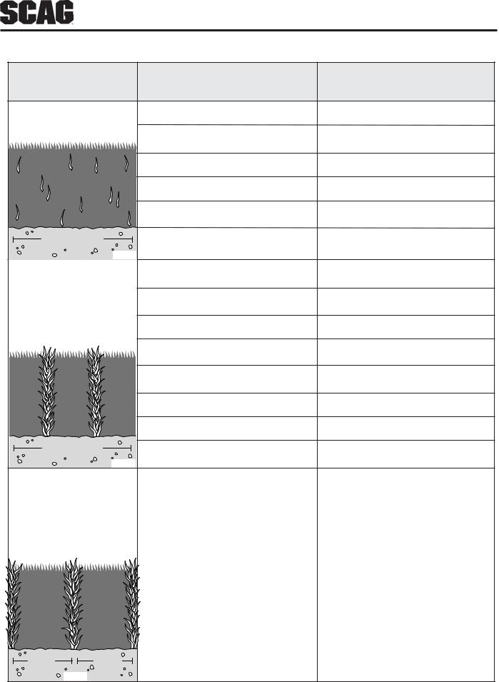
Stringers - Occasional |
Low engine RPM |
Run engine at full 3600 RPM |
Blades of Uncut |
|
|
Grass |
Ground speed too fast |
Slow speed to adjust for conditions |
|
Wet grass |
Cut grass after it has dried out |
|
Dull blades, incorrect sharpening |
Sharpen blades |
|
Deck plugged, grass accumulation |
Clean underside of deck |
Width of Deck |
Belts slipping |
Adjust belt tensions |
SGB020 |
|
|
Streaking - Strips of |
Dull, worn blades |
Sharpen blades |
Uncut Grass in Cutting |
|
|
Path |
Incorrect blade sharpening |
Sharpen blades |
|
Low engine RPM |
Run engine at full 3600 RPM |
|
Belt slipping |
Adjust belt tension |
|
Deck plugged, grass accumulation |
Clean underside of deck |
|
Ground speed too fast |
Slow speed to adjust for conditions |
|
Wet grass |
Cut grass after it has dried out |
Width of Deck |
Bent blades |
Replace blades |
|
||
SGB018 |
|
|
Streaking - Strips of |
Not enough overlapping |
Increase the overlap of each |
Uncut Grass Between |
between rows |
pass |
Cutting Paths |
|
|
Width |
Width |
of |
of |
Deck |
SGB019 Deck |
15

TROUBLESHOOTING CUTTING CONDITIONS
CONDITION |
CAUSE |
CURE |
Uneven Cut on Flat |
Lift worn off of blade |
Replace blade |
Ground - Wavy |
|
|
High-Low |
Blade upside down |
Mount with cutting edge toward |
Appearance, |
|
ground |
Scalloped Cut, or |
|
|
Rough Contour |
Deck plugged, grass accumulation |
Clean underside of deck |
|
Too much blade angle (deck pitch) |
Adjust pitch and level |
|
Deck mounted improperly |
See your authorized SCAG dealer |
|
Bent spindle area |
See your authorized SCAG dealer |
|
Dull blade |
Sharpen blade |
Width of Deck |
|
|
SGB020 |
|
|
Uneven Cut on |
Uneven ground |
May need to reduce ground speed, |
Uneven Ground - |
|
raise cutting height, and/or change |
Wavy Appearance, |
|
direction of cut |
High-Low Scalloped |
|
|
Cut, or Rough Contour |
|
|
Width of Deck |
|
|
SGB021 |
|
|
Sloping Ridge Across |
Tire pressures not equal |
Check and adjust tire pressure |
Width of Cutting Path |
|
|
|
Wheels uneven |
Check and adjust tire pressure |
|
Deck mounted incorrectly |
See your authorized SCAG dealer |
 Width of Deck
SGB023
16
 Loading...