


INSTALLATION INSTRUCTIONS
– W-3WAY ECO-i System Air Conditioner – for Refrigerant R410A
This air conditioner uses the new refrigerant R410A.
NOTE External diameter of service port R410A: 5/16"
 R410A Models
Indoor Units
|
Class |
7 |
9 |
12 |
18 |
24 |
36 |
48 |
X |
4-Way Air Discharge Semi-Concealed Type |
|
|
XHX1252 |
XHX1852 |
XHX2452 |
XHX3652 |
|
XM |
4-Way Air Discharge Semi-Concealed Type |
|
|
XMHX1252 XMHX1852 |
|
|
|
|
A |
1-Way Air Discharge Semi-Concealed Type |
AHX0752 |
AHX0952 |
AHX1252 |
|
|
|
|
U |
Concealed Duct Type |
UHX0752 |
|
UHX1252 |
UHX1852 |
UHX2452 |
UHX3652 |
|
D |
Concealed Duct |
|
|
|
|
|
DHX3652 |
DHX4852 |
High-Static Pressure Type |
|
|
|
|
|
|||
|
|
|
|
|
|
|
|
|
T |
Ceiling-Mounted Type |
|
|
THX1252 |
THX1852 |
THX2452 |
|
|
|
|
|
|
|
|
|
|
|
K |
Wall-Mounted Type |
KHX0752 |
KHX0952 |
KHX1252 |
KHX1852 |
KHX2452 |
|
|
Outdoor Units |
|
|
|
|
|
|
|
|
|
Class |
90 |
140 |
|
|
|
|
|
C |
ECO-i W-3WAY |
CHDZ09053 |
CHDZ14053 |
|
|
|
|
|
CHDZR09053 CHDZR14053 |
|
|
|
|
||||
|
|
|
|
|
|
|||
* Refrigerant R410A is used in the outdoor units.
Optional Controllers
Timer Wired Remote Controller |
RCS-TM80BG |
|
Wireless Remote Controller (For U, D Types) |
RCS-BH80AAB.WL |
|
Wireless Remote Controller (For X Type) |
RCS-SH80AAB.WL |
|
Wireless Remote Controller (For XM Type) |
RCS-XM18AAB.WL |
|
Wireless Remote Controller (For A, T Types) |
RCS-TRP80AAB.WL |
|
RC Wireless Remote Controller (For K Type) |
RCS-SH1AAB |
|
Simplified Remote Controller |
RCS-KR1AGB |
|
System Controller |
SHA-KC64UG |
|
Intelligent Controller |
SHA-KT256BA |
|
Communication Adaptor |
SHA-KA128AAB |
|
Remote Sensor |
ART-K45AGB |
|
LonWorks Interface |
SHA-LN16UAB |
|
|
SANYO Commercial Solutions |
In Canada |
|
A division of SANYO North America Corporation |
SANYO Canada Inc. |
|
Cornerstone Business Park |
1-300 Applewood Crescent |
|
1062 Thorndale Avenue |
Concord, Ontario |
85464369098000 ©SANYO 2008 |
Bensenville, IL 60106, U.S.A. |
L4K 5C7, Canada |
|
a |
|
X
XM
A
U
D
T
K
W-3WAY_ECO-i_US.indd a |
2008/02/07 10:55:34 |
|
|
|
|
|
|
||
|
|
|
||
|
|
|
|
|
IMPORTANT!
Please Read Before Starting
This air conditioning system meets strict safety and operating standards. As the installer or service person, it is an important part of your job to install or service the system so it operates safely and efficiently.
For safe installation and trouble-free operation, you must:
●Carefully read this instruction booklet before beginning.
●Follow each installation or repair step exactly as shown.
●Observe all local, state, and national electrical codes.
●Pay close attention to all warning and caution notices given in this manual.
This symbol refers to a hazard or
WARNING unsafe practice which can result in severe personal injury or death.
This symbol refers to a hazard or
unsafe practice which can result CAUTION in personal injury or product or
property damage.
If Necessary, Get Help
These instructions are all you need for most installation sites and maintenance conditions. If you require help for a special problem, contact our sales/service outlet or your certified dealer for additional instructions.
In Case of Improper Installation
The manufacturer shall in no way be responsible for improper installation or maintenance service, including failure to follow the instructions in this document.
SPECIAL PRECAUTIONS
 WARNING When Wiring
ELECTRICAL SHOCK CAN CAUSE
SEVERE PERSONAL INJURY OR DEATH.
ONLY A QUALIFIED, EXPERIENCED
ELECTRICIAN SHOULD ATTEMPT TO
WIRE THIS SYSTEM.
•Do not supply power to the unit until all wiring and tubing are completed or reconnected and checked.
•Highly dangerous electrical voltages are used in this system. Carefully refer to the wiring diagram and these instructions when wiring. Improper connections and inadequate grounding can cause accidental injury or death.
•Ground the unit following local electrical codes.
•Connect all wiring tightly. Loose wiring may cause overheating at connection points and a possible fire hazard.
When Transporting
Be careful when picking up and moving the indoor and outdoor units. Get a partner to help, and bend your knees when lifting to reduce strain on your back. Sharp edges or thin aluminum fins on the air conditioner can cut your fingers.
When Installing…
…In a Room
Properly insulate any tubing run inside a room to prevent “sweating” that can cause dripping and water damage to walls and floors.
…In Moist or Uneven Locations
Use a raised concrete pad or concrete blocks to provide a solid, level foundation for the outdoor unit. This prevents water damage and abnormal vibration.
…In an Area with High Winds
Securely anchor the outdoor unit down with bolts and a metal frame. Provide a suitable air baffle.
…In a Snowy Area (for Heat Pump-type Systems)
Install the outdoor unit on a raised platform that is higher than drifting snow. Provide snow vents.
When Connecting Refrigerant Tubing
•Ventilate the room well, in the event that is refrigerant gas leaks during the installation. Be careful not to allow contact of the refrigerant gas with a flame as this will cause the generation of poisonous gas.
•Keep all tubing runs as short as possible.
•Use the flare method for connecting tubing.
•Apply refrigerant lubricant to the matching surfaces of the flare and union tubes before connecting them, then tighten the nut with a torque wrench for a leak-free connection.
•Check carefully for leaks before starting the test run.
When Servicing
•Turn the power OFF at the main power box (mains) before opening the unit to check or repair electrical parts and wiring.
•Keep your fingers and clothing away from any moving parts.
•Clean up the site after you finish, remembering to check that no metal scraps or bits of wiring have been left inside the unit being serviced.
CAUTION
•Ventilate any enclosed areas when installing or testing the refrigeration system. Escaped refrigerant gas, on contact with fire or heat, can produce dangerously toxic gas.
•Confirm after installation that no refrigerant gas is leaking. If the gas comes in contact with a burning stove, gas water heater, electric room heater or other heat source, it can cause the generation of poisonous gas.
2
W-3WAY_ECO-i_US.indd 2 |
2008/02/07 10:55:36 |
|
|
|
|
|
|
||
|
|
|
||
|
|
|
|
|

Check of Density Limit
The room in which the air conditioner is to be installed requires a design that in the event of refrigerant gas leaking out, its density will not exceed a set limit.
The refrigerant (R410A), which is used in the air conditioner, is safe, without the toxicity or combustibility of ammonia, and is not restricted by laws imposed to protect the ozone layer. However, since it contains more than air, it poses
the risk of suffocation if its density should rise excessively. Suffocation from leakage of refrigerant is almost non-exis- tent. With the recent increase in the number of high density buildings, however, the installation of multi air conditioner systems is on the increase because of the need for effective use of floor space, individual control, energy conservation by curtailing heat and carrying power, etc.
Most importantly, the multi air conditioner system is able to replenish a large amount of refrigerant compared to conventional individual air conditioners. If a single unit of the multi air conditioner system is to be installed in a small room, select a suitable model and installation procedure so that if the refrigerant accidentally leaks out, its density does not reach the limit (and in the event of an emergency, measures can be made before injury can occur).
In a room where the density may exceed the limit, create an opening with adjacent rooms, or install mechanical ventilation combined with a gas leak detection device. The density is as given below.
Total amount of refrigerant (lbs)
Min. volume of the indoor unit installed room (ft.3) < Density limit (oz/ft.3)
The density limit of refrigerant which is used in multi air conditioners is 0.3 oz/ft.3 (ISO 5149).
2. The standards for minimum room volume are as follows.
(1) No partition (shaded portion)
(2)When there is an effective opening with the adjacent room for ventilation of leaking refrigerant gas (opening without a door, or an opening 0.15% or larger than the respective floor spaces at the top or bottom of the door).

 Outdoor unit
 Refrigerant tubing
Indoor unit |
(3)If an indoor unit is installed in each partitioned room and the refrigerant tubing is interconnected, the smallest room of course becomes the object. But when mechanical ventilation is installed interlocked with a gas leakage detector in the smallest room where the density limit is exceeded, the volume of the next smallest room becomes the object.
|
|
Refrigerant tubing |
|
|
Outdoor unit |
Very |
|
|
small |
|
Indoor unit |
room |
|
|
|
|
|
Small |
Medium |
Large room |
room |
room |
|
Mechanical ventilation device – Gas leak detector
NOTE
1.If there are 2 or more refrigerating systems in a single refrigerating device, the amount of refrigerant should be as charged in each independent device.
For the amount of charge in this example:
Outdoor unit
e.g., charged
amount (353 oz) e.g., charged amount (529 oz)
Indoor unit
Room A Room B Room C Room D Room E Room F
The possible amount of leaked refrigerant gas in rooms A, B and C is 353 oz.
The possible amount of leaked refrigerant gas in rooms D, E and F is 529 oz.
3.The minimum indoor floor space compared with the amount of refrigerant is roughly as follows: (When the ceiling is 8.8 ft. high)
|
ft.3 |
|
|
|
|
|
|
|
|
|
|
ft.2 |
|
|
|
4000 |
|
|
|
|
|
|
|
|
|
|
|
454 |
|
|
|
|
|
|
|
|
|
|
|
|
|
|
||
|
|
|
|
|
|
|
|
|
|
|
|
|
|
|
|
3500 |
|
Range below |
|
|
|
|
|
|
398 |
indoorMin. floor area ceilingthe(when is 8.8 ft. high) |
|||
|
|
|
|
|
|
|
|
|||||||
|
3000 |
|
the density limit of |
|
|
|
|
341 |
||||||
indoorMin. volume |
|
0.3 oz/ft.3 |
|
|
|
|
|
|
||||||
|
|
|
(countermeasures |
|
|
|||||||||
500 |
|
(countermeasures |
|
|
57 |
|||||||||
|
2500 |
|
not needed) |
|
|
|
|
|
|
284 |
|
|||
|
2000 |
|
|
|
|
|
|
|
|
|
|
|
227 |
|
|
1500 |
|
|
|
|
|
Range above |
|
170 |
|
||||
|
|
|
|
|
|
|
|
|
|
|||||
|
1000 |
|
|
|
|
|
the density limit of |
|
114 |
|
||||
|
|
|
|
|
|
|
|
|||||||
|
|
|
|
|
|
|
0.3 oz/ft.3 |
|
|
|
|
|
||
|
0 |
|
|
|
|
|
needed) |
|
|
|
0 |
|
||
|
|
|
|
|
|
|
|
|
|
|
|
|
||
|
|
|
|
|
|
|
|
|
|
|
|
|
||
|
0 |
200 |
400 |
600 |
800 |
1000 |
1200 |
|
||||||
|
|
|
|
|
|
|
|
|
|
|
|
|
oz |
|
Total amount of refrigerant
3
W-3WAY_ECO-i_US.indd 3 |
2008/02/07 10:55:36 |
|
|
|
|
|
|
||
|
|
|
||
|
|
|
|
|
Precautions for Installation Using New Refrigerant
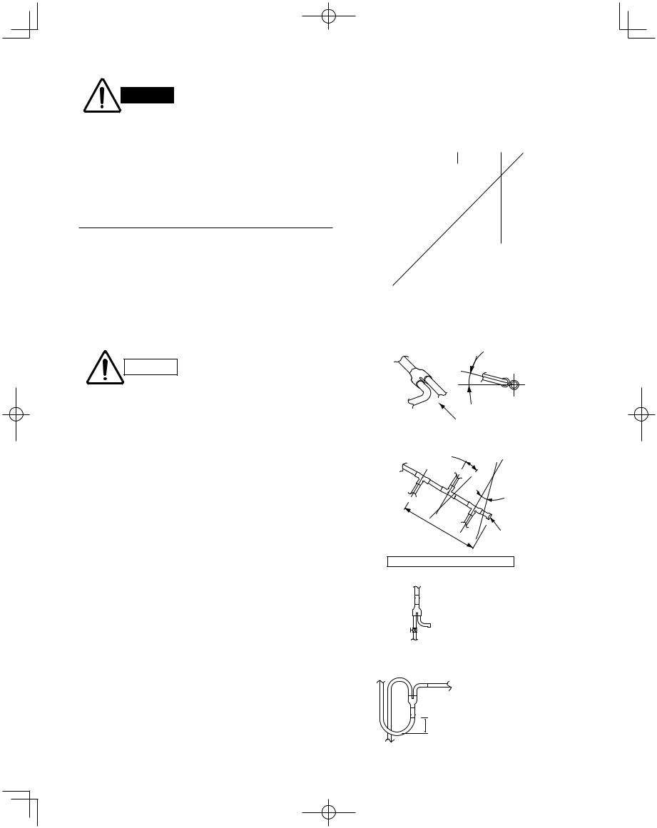
1. Care regarding tubing
1-1. Process tubing
●Material: Use C1220 phosphorous deoxidized copper specified in JIS H3300 “Copper and Copper Alloy Seamless Pipes and Tubes.”
For tubes of ø7/8" (ø22.22 mm) or larger, use C1220 T-1/2H material or H material, and do not bend the tubes.
●Tubing size: Be sure to use the sizes indicated in the table below.
●Use a tube cutter when cutting the tubing, and be sure to remove any flash. This also applies to distribution joints (optional).
●When bending tubing, use a bending radius that is 4 times the outer diameter of the tubing or larger.
Use sufficient care in handling the tubing. Seal the tubing ends with caps or tape to CAUTION prevent dirt, moisture, or other foreign substances from entering. These substances
can result in system malfunction.
|
|
|
|
|
|
Unit: in. (mm) |
|
|
|
|
|
|
|
|
|
|
|
Material |
|
|
O |
|
|
|
||
Copper tube |
Outer diameter |
1/4 (6.35) |
3/8 (9.52) |
1/2 (12.7) |
5/8 (15.88) |
3/4 (19.05) |
|
|
|
|
|
|
|
|
|
||
Wall thickness |
1/32 (0.8) |
1/32 (0.8) |
1/32 (0.8) |
5/128 (1.0) |
over 5/128 (1.0) |
Unit: in. (mm) |
||
|
||||||||
|
|
|
|
|
|
|
||
|
|
|
|
|
|
|
||
Material |
|
|
1/2 H, H |
|
|
|||
Copper tube |
Outer diameter |
7/8 (22.22) |
1 (25.4) |
1-1/8 (28.58) |
1-1/4 (31.75) |
1-1/2 (38.1) |
1-5/8 (41.28) |
|
|
|
|
|
|
|
|
||
Wall thickness |
5/128 (1.0) |
5/128 (1.0) |
5/128 (1.0) |
3/64 (1.1) |
over 3/64 (1.15) |
over 3/64 (1.20) |
||
|
||||||||
|
|
|
|
|
|
|
|
|
1-2. Prevent impurities including water, dust and oxide from entering the tubing. Impurities can cause R410A refrigerant deterioration and compressor defects. Due to the features of the refrigerant and refrigerating machine oil, the prevention of water and other impurities becomes more important than ever.
2. Be sure to recharge the refrigerant only in liquid form.
2-1. Since R410A is a non-azeotrope, recharging the refrigerant in gas form can lower performance and cause defects in the unit.
2-2. Since refrigerant composition changes and performance decreases when gas leaks, collect the remaining refrigerant and recharge the required total amount of new refrigerant after fixing the leak.
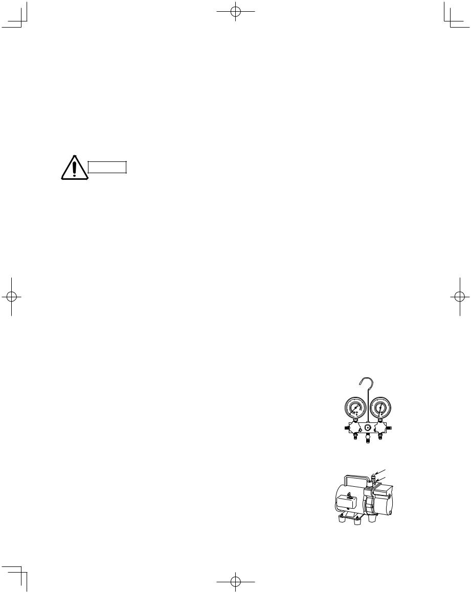
3. Different tools required
3-1. Tool specifications have been changed due to the characteristics of R410A. Some tools for R22and R407C-type refrigerant systems cannot be used.
|
New |
R407C tools |
|
|
Item |
compatible |
Remarks |
||
tool? |
||||
|
|
with R410A? |
|
|
Manifold gauge |
Yes |
No |
Types of refrigerant, refrigerating machine |
|
|
|
|
oil, and pressure gauge are different. |
|
|
|
|
|
|
Charge hose |
Yes |
No |
To resist higher pressure, material must be changed. |
|
|
|
|
|
|
Vacuum pump |
Yes |
Yes |
Use a conventional vacuum pump if it is equipped |
|
|
|
|
with a check valve. If it has no check valve, |
|
|
|
|
purchase and attach a vacuum pump adapter. |
|
|
|
|
|
|
Leak detector |
Yes |
No |
Leak detectors for CFC and HCFC that |
|
|
|
|
react to chlorine do not function because |
|
|
|
|
R410A contains no chlorine. Leak detector |
|
|
|
|
for HFC134a can be used for R410A. |
|
|
|
|
|
|
Flaring oil |
Yes |
No |
For systems that use R22, apply mineral oil (Suniso oil) |
|
|
|
|
to the flare nuts on the tubing to prevent refrigerant |
|
|
|
|
leakage. For machines that use R407C or R410A, apply |
|
|
|
|
synthetic oil (ether oil) to the flare nuts. |
|
|
|
|
|
* Using tools for R22 and R407C and new tools for R410A together can cause defects.
4
Manifold gauge
Vacuum pump
Outlet
Inlet
W-3WAY_ECO-i_US.indd 4 |
2008/02/07 10:55:37 |
|
|
|
|
|
|
||
|
|
|
||
|
|
|
|
|

3-2. Use R410A exclusive cylinder only.
Valve
Single-outlet valve
(with siphon tube)
Liquid refrigerant should be recharged with the cylinder standing on end as shown.
New refrigerant R410A cannot be used for earlier models
1. Compressor specifications are different.
If recharging a R22 or R407C compressor with R410A, durability will significantly decrease since some of the materials used for compressor parts are different.
2. Existing tubing cannot be used (especially R22).
Completely cleaning out residual refrigerating
machine oil is impossible, even by flushing.
3. Refrigerating machine oil differs (R22).
Since R22 refrigerating machine oil is mineral oil, it does not dissolve in R410A. Therefore, refrigerating machine oil discharged from the compressor can cause compressor damage.
R22 refrigerating machine oil |
Mineral oil (Suniso oil) |
|
|
|
|
|
|
R407C refrigerating machine oil |
Synthetic fluid (ether oil) |
|
|
|
|
|
|
R410A refrigerating machine oil |
Synthetic fluid (ether oil) |
|
|
|
|
|
|
|
|
|
|
|
|
|
|
 Liquid
R410A
5
W-3WAY_ECO-i_US.indd 5 |
2008/02/07 10:55:37 |
|
|
|
|
|
|
||
|
|
|
||
|
|
|
|
|
CONTENTS
Page
IMPORTANT! . . . . . . . . . . . . . . . . . . . . . . . . . . . . .2
Please Read Before Starting Check of Density Limit
Precautions for Installation Using New Refrigerant
New refrigerant R410A cannot be used for earlier models
1.GENERAL . . . . . . . . . . . . . . . . . . . . . . . . . . . . .8
1-1. Tools Required for Installation (not supplied)
1-2. Accessories Supplied
1-3. Type of Copper Tube and Insulation Material 1-4. Additional Materials Required for Installation 1-5. Tubing Length
1-6. Tubing Size
1-7. Straight Equivalent Length of Joints
1-8. Additional Refrigerant Charge
1-9. System Limitations
1-10. Installation Standards
1-11. Check of Limit Density
1-12. Installing Distribution Joint
1-13. Optional Distribution Joint Kits
1-14. Optional Solenoid Valve Kit
1-15. Example of Tubing Size Selection and Refrigerant Charge Amount
2.SELECTING THE INSTALLATION SITE . . . . 23
2-1. Indoor Unit
2-2. Outdoor Unit
2-3. Precautions When Installing in Heavy Snow Areas
2-4. Dimensions of Wind Ducting
2-5. Dimensions of Snow Ducting
3.HOW TO INSTALL THE INDOOR UNIT . . . . . 28
4-Way Air Discharge Semi-Concealed Type (X Type)
3-1. Preparation for Suspending
3-2. Suspending the Indoor Unit
3-3. Placing the Unit Inside the Ceiling
3-4. Installing the Drain Piping
3-5. Checking the Drainage
3-6. How to Install the Ceiling Panel
3-7. Special Remarks
(XM Type)
3-8. Preparation for Suspending
3-9. Suspending the Indoor Unit
3-10. Placing the Unit Inside the Ceiling
3-11. Installing the Drain Piping
3-12. Checking the Drainage
3-13. How to Install the Ceiling Panel
Page
1-Way Air Discharge Semi-Concealed Type (A Type)
3-14. Suspending the Indoor Unit
3-15. Placing the Unit Inside the Ceiling
3-16. Installing the Drain Piping
3-17. Checking the Drainage
3-18. Electrical Power Wiring
3-19. How to Install the Ceiling Panel
Concealed Duct Type (U Type)
3-20. Required Minimum Space for Installation and Service
3-21. Suspending the Indoor Unit
3-22. Installing the Drain Piping
3-23. Checking the Drainage
3-24. Increasing the Fan Speed
Concealed Duct High-Static Pressure Type (D Type)
3-25. Required Minimum Space for Installation and Service
3-26. Suspending the Indoor Unit
3-27. Installing the Drain Piping
3-28. Caution for Ducting Work
3-29. Indoor Fan Performance
Ceiling-Mounted Type (T Type)
3-30. Required Minimum Space for Installation and Service
3-31. Suspending the Indoor Unit
3-32. Duct for Fresh Air
3-33. Shaping the Tubing
3-34. Installing the Drain Piping
Wall-Mounted Type (K Type)
3-35. Removing the Rear Panel from the Unit 3-36. Selecting and Making a Hole
3-37. Installing the Rear Panel onto the Wall 3-38. Removing the Grille to Install the Indoor Unit 3-39. Preparing the Tubing
3-40. Shaping the Tubing
3-41. Installing the Drain Hose
3-42. When Using Wireless Remote Controller
Instead of Wired Remote Controller
4.HOW TO INSTALL THE OUTDOOR UNIT . . . 64
4-1. Transporting
4-2. Installing the Outdoor Unit
4-3. Remove the Brackets Used for Transport
4-4. Routing the Tubing
4-5. Prepare the Tubing
4-6. Connect the Tubing
6
W-3WAY_ECO-i_US.indd 6 |
2008/02/07 10:55:37 |
|
|
|
|
|
|
||
|
|
|
||
|
|
|
|
|
Page
5.ELECTRICAL WIRING . . . . . . . . . . . . . . . . . . 68
5-1. General Precautions on Wiring
5-2. Recommended Wire Length and Wire Diameter for Power Supply System
5-3. Wiring System Diagram
5-4. Important Note When Wiring for Common Type
5-5. Important Note When Wiring for XM Type
6. HOW TO PROCESS TUBING . . . . . . . . . . . . 76
6-1. Connecting the Refrigerant Tubing
6-2. Connecting Tubing Between Indoor and
Outdoor Units
6-3. Insulating the Refrigerant Tubing
6-4. Taping the Tubes
6-5. Finishing the Installation
7. AIR PURGING . . . . . . . . . . . . . . . . . . . . . . . . . 80
Air Purging with a Vacuum Pump (for Test Run) Preparation
8.TEST RUN . . . . . . . . . . . . . . . . . . . . . . . . . . . . 83
8-1. Preparing for Test Run
8-2. Test Run Procedure
8-3. Main Outdoor Unit PCB Setting
8-4. Auto Address Setting
8-5. Remote Controller Test Run Settings
8-6. Caution for Pump Down
8-7. Meaning of Alarm Messages
9.APPENDIX . . . . . . . . . . . . . . . . . . . . . . . . . . . 97
9-1. 4-Way Air Discharge Semi-Concealed Type (X, XM Types)
9-2. 1-Way Air Discharge Semi-Concealed Type (A Type)
9-3. Concealed Duct (High-Static Pressure) Type (U, D Types)
9-4. Ceiling-Mounted Type (T Type)
9-5. Wall-Mounted Type (K Type)
7
W-3WAY_ECO-i_US.indd 7 |
2008/02/07 10:55:37 |
|
|
|
|
|
|
||
|
|
|
||
|
|
|
|
|
1. GENERAL
This booklet briefly outlines where and how to install the air conditioning system. Please read over the entire set of instructions for the outdoor unit and make sure all accessory parts listed are with the system before beginning.
1-1. Tools Required for Installation (not supplied)
1.Flathead screwdriver
2.Phillips head screwdriver
3.Knife or wire stripper
4.Tape measure
5.Carpenter’s level
6.Sabre saw or key hole saw
7.Hacksaw
8.Core bits
9.Hammer
10. Drill
11. Tube cutter
12. Tube flaring tool
13. Torque wrench
14. Adjustable wrench
15. Reamer (for deburring)
1-2. Accessories Supplied
See Tables 1-1 – 1-8.
Table 1-1 Outdoor Unit
Part name |
|
Figure |
|
|
Outer |
Inner |
|
|
diameter |
diameter |
|
Connection tubing |
ø1-1/8" |
ø1" |
|
Outer |
Inner |
||
|
|||
|
diameter |
diameter |
|
|
ø7/8" |
ø3/4" |
1-3. Type of Copper Tube and Insulation Material
If you wish to purchase these materials separately from a local source, you will need:
1.Deoxidized annealed copper tube for refrigerant tubing.
2.Foamed polyethylene insulation for copper tubes as required to precise length of tubing. Wall thickness of the insulation should be not less than 5/16 in.
3.Use insulated copper wire for field wiring. Wire size varies with the total length of wiring.
Refer to “5. ELECTRICAL WIRING” for details.
Check local electrical codes and
CAUTION regulations before obtaining
wire. Also, check any specified instructions or limitations.
1-4. Additional Materials Required for Installation
1.Refrigeration (armored) tape
2.Insulated staples or clamps for connecting wire (See your local codes.)
3.Putty
4.Refrigeration tubing lubricant
5.Clamps or saddles to secure refrigerant tubing
6.Scale for weighing
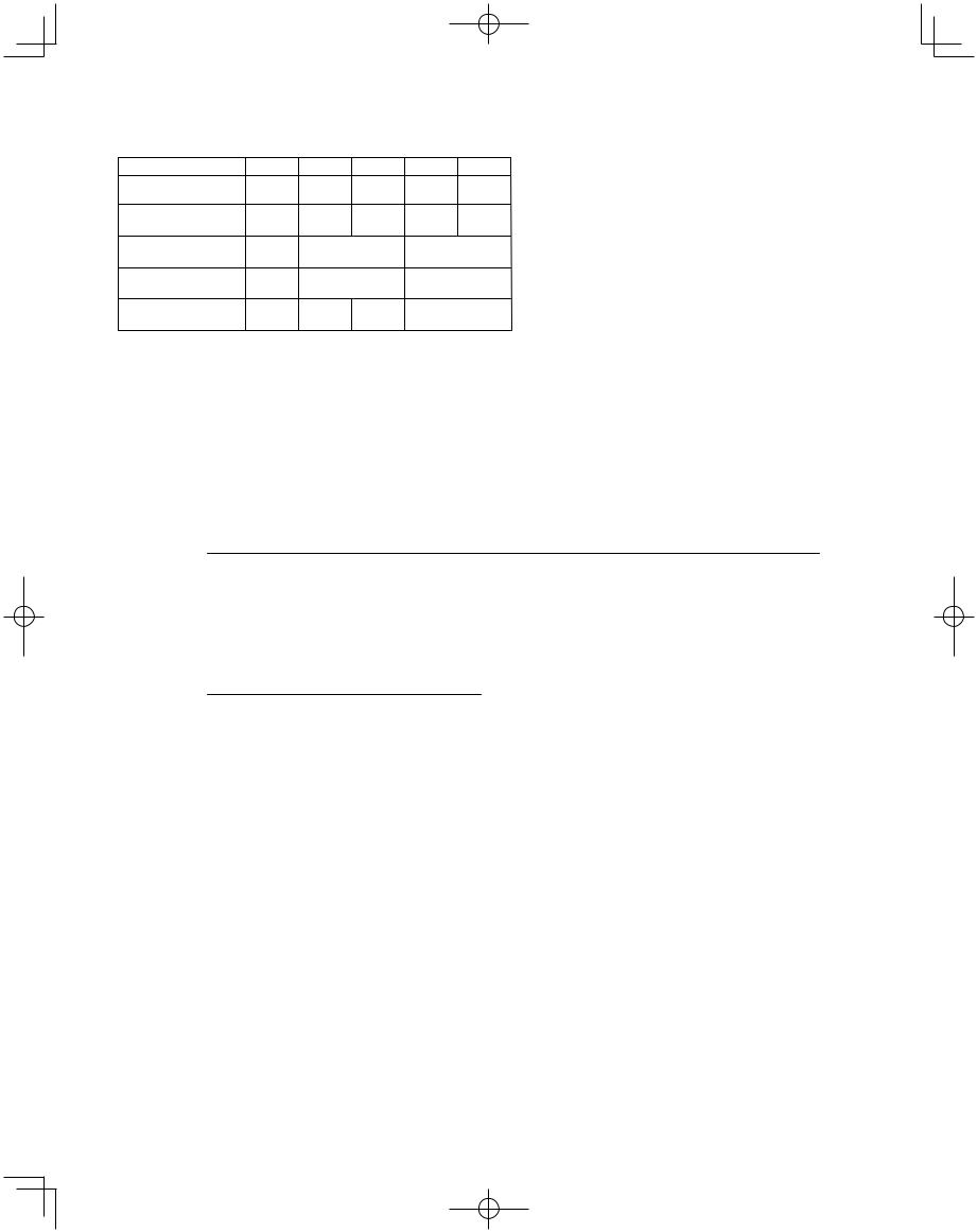
|
Q’ty |
09053 Model |
14053 Model |
(10 hp) |
(16 hp) |
0 |
1 |
1 |
0 |
Instruction manual |
paper |
1 |
1 |
(hp = horse power)
8
W-3WAY_ECO-i_US.indd 8 |
2008/02/07 10:55:38 |
|
|
|
|
|
|
||
|
|
|
||
|
|
|
|
|

Table 1-2 (4-Way Air Discharge Semi-Concealed) (X-Type)
Part Name |
Figure |
Q’ty |
Remarks |
|
Full-scale installation diagram |
|
1 |
Printed on container box |
|
Drain hose |
|
1 |
For securing drain hose |
|
Hose band |
|
1 |
For securing drain hose |
|
Drain insulator |
|
1 |
For drain joint |
|
Flare insulator |
|
1 |
For liquid tube |
|
|
1 |
For gas tube |
||
|
|
|||
Insulating tape |
White |
2 |
For gas tube joint |
|
(heat-resisting) |
||||
|
|
|
||
Packing |
|
1 |
For drain joint |
|
Wiring cover |
|
1 |
For covering electrical wiring |
|
Screw |
|
4 |
For full-scale installation diagram |
|
Washer |
|
8 |
For suspending indoor unit from ceiling |
|
Screw |
|
1 |
For fixing the wiring cover |
Table 1-3 (1-Way Air Discharge Semi-Concealed)
Part Name |
Figure |
Q’ty |
Remarks |
|
Full-scale installation diagram |
|
1 |
Printed on container box |
|
Drain hose |
|
1 |
For securing drain hose |
|
Hose band |
|
1 |
For securing drain hose |
|
Drain insulator |
|
1 |
For drain joint |
|
Flare insulator |
|
1 |
For liquid tube |
|
|
1 |
For gas tube |
||
|
|
|||
Insulating tape |
White |
2 |
For gas tube joint |
|
(heat-resisting) |
||||
|
|
|
||
Packing |
|
1 |
For drain joint |
|
Washer |
|
8 |
For suspending indoor unit from ceiling |
|
Screw |
|
4 |
For full-scale installation diagram |
|
Bushing |
|
1 |
For electrical junction box |
Table 1-4 (Concealed Duct)
Part Name |
Figure |
Q’ty |
Remarks |
|
Drain hose |
|
1 |
For securing drain hose |
|
Hose band |
|
1 |
For securing drain hose |
|
Packing |
|
1 |
For drain joint |
|
Drain insulator |
|
1 |
For drain joint |
|
Flare insulator |
|
1 |
For liquid tube |
|
Insulating tape |
White |
2 |
For gas and liquid tubes flare nuts |
|
(heat-resisting) |
||||
|
|
|
||
Flare insulator |
|
1 |
For gas tube |
|
Washer |
|
8 |
For suspending indoor unit from ceiling |
|
Sealing putty |
|
1 |
For sealing recessed portion of power supply |
|
Vinyl clamp |
|
8 |
For flare and drain insulators |
●Use M10 or 3/8" for suspending bolts.
●Field supply for suspending bolts and nuts.
9
W-3WAY_ECO-i_US.indd 9 |
2008/02/07 10:55:38 |
|
|
|
|
|
|
||
|
|
|
||
|
|
|
|
|
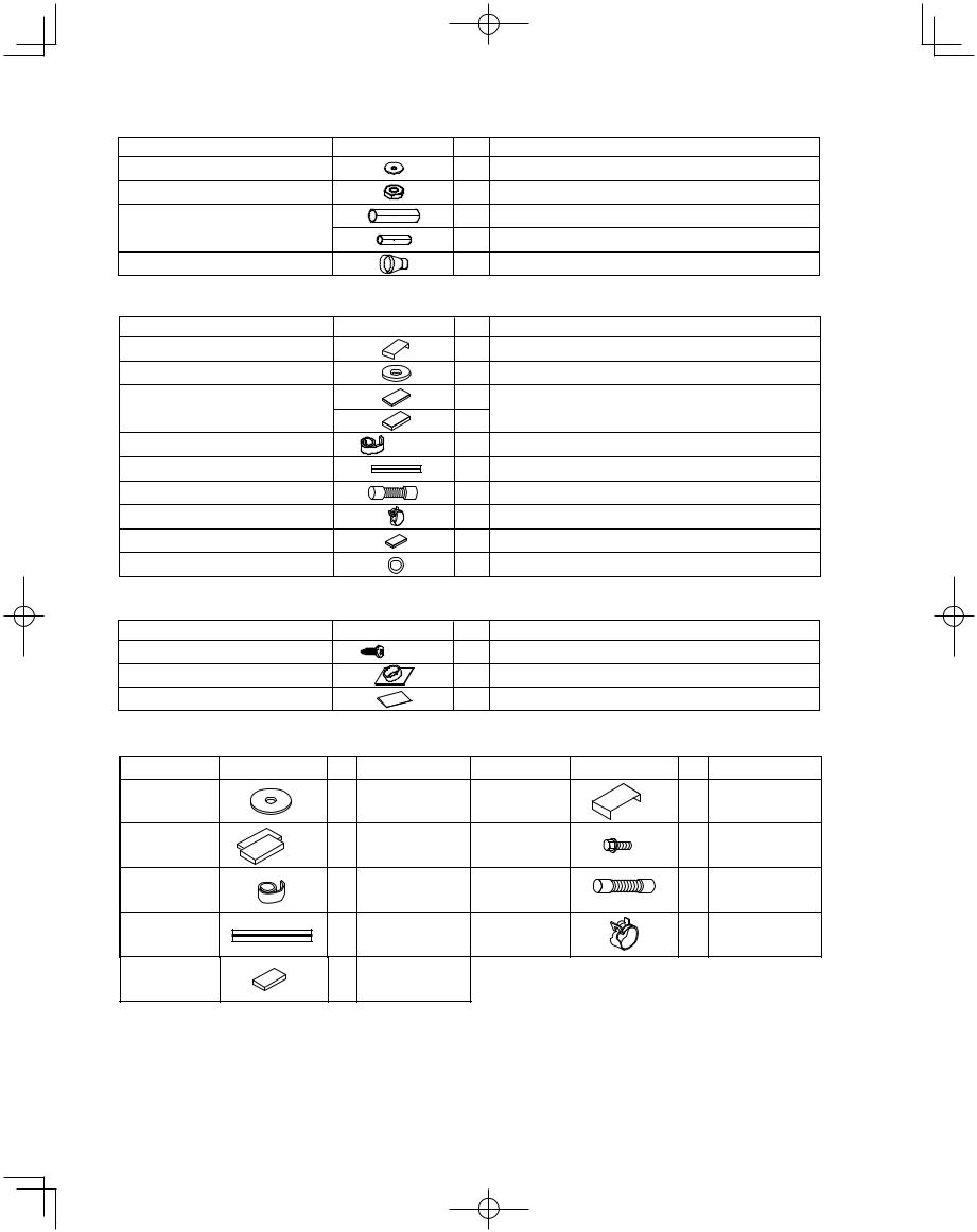
Table 1-5 (Concealed Duct High-Static Pressure)
Part Name |
Figure |
Q’ty |
Remarks |
Washer |
|
8 |
For suspending indoor unit from ceiling |
Nut |
|
8 |
For suspending indoor unit from ceiling |
Flare insulator |
|
1 |
For gas tube |
|
|
|
|
|
|
1 |
For liquid tube |
Drain socket |
|
1 |
For drain pipe connection |
Table 1-6 (Ceiling-Mounted)
Part Name |
Figure |
Q’ty |
Remarks |
Full-scale installation diagram |
|
1 |
Printed on container box |
Washer |
|
4 |
For temporarily suspending indoor unit from ceiling |
Flare insulator |
T1/8" |
2 |
For gas and liquid tube joints |
|
|||
|
2 |
||
|
T3/16" |
|
|
|
|
|
|
Insulating tape |
White |
2 |
For gas and liquid tubes flare nuts |
(heat-resisting) |
|||
Vinyl clamp |
|
8 |
For flare and drain insulators |
Drain hose |
L5-1/2" |
1 |
For main unit and PVC pipe joints |
|
|
|
|
Hose band |
|
2 |
For drain hose connection |
Drain insulator |
|
1 |
For drain hose joint |
Gum eyelet |
|
2 |
For power supply inlet and 3 way wiring inlet |
Table 1-7 (Wall-Mounted)
Part Name |
Figure |
Q’ty |
Remarks |
Tapping screw |
5/32" s 1" |
10 |
For fixing the rear panel |
Plastic cover |
|
1 |
For improved tubing appearance |
Insulator |
|
1 |
For insulating flare nut (2452 type only) |
Table 1-8 (4-Way Air Discharge Semi-Concealed) (XM Type)
Parts Name |
Figure |
Q'ty |
Remarks |
Parts Name |
Figure |
Q'ty |
Remarks |
|
|
|
For temporarily |
Full-scale |
|
|
Printed on |
Washer |
|
8 |
suspending indoor |
installation |
|
1 |
|
|
|
container box |
|||||
|
|
|
unit from ceiling |
diagram |
|
|
|
|
|
|
|
|
|
||
Flare |
T3 |
2 |
For gas / |
Washer head |
|
|
For full-scale |
liquid tube |
|
4 |
installation |
||||
insulation |
T5 |
set |
screw |
|
|||
connection |
|
|
diagram |
||||
|
|
|
|
|
|
||
|
|
|
For gas / |
|
|
|
For unit & PVC |
Insulation tie |
|
2 liquid tube / flare |
Drain hose |
|
1 |
||
|
L140 |
tube connection |
|||||
|
|
|
nut connection |
|
|
||
|
|
|
|
|
|
||
Vinyl tie |
|
8 |
For flare / drain |
Hose band |
|
2 |
For drain hose |
|
insulating |
|
|||||
|
|
connection |
|||||
|
|
|
connection |
|
|
|
|
|
|
|
|
|
|
|
|
Drain hose |
|
1 |
For drain tube |
|
|
|
|
insulation |
T10 |
connection |
|
|
|
|
|
|
|
|
|
|
|||
●Use M10 or 3/8" for suspending bolts.
●Field supply for suspending bolts and nuts.
10
W-3WAY_ECO-i_US.indd 10 |
2008/02/21 16:33:30 |
|
|
|
|
|
|
||
|
|
|
||
|
|
|
|
|
1-5. Tubing Length
Select the installation location so that the length and size of refrigerant tubing are within the allowable range shown
in the figure below. |
1. |
|
Main tubing length LM = LA + LB … b 262 ft. |
||
|
|||||
|
|
|
2. |
|
Main distribution tubes LC – LH are selected according to the capacity after the |
|
|
|
|
||
|
|
|
|
|
distribution joint. |
|
|
|
3. |
|
Sizes of indoor unit connection tubing 1 – 40 are determined by the connection tubing |
|
|
|
|
||
|
|
|
|
|
sizes on the indoor units. |
|
|
|
|
||
|
|
|
|
|
|
H3 C |
|
L2 |
|
LM |
L1 |
|
|
|
B |
|
|
|
T-joint tubing |
|
|
|
Balance tubing |
LB |
LC |
LD |
LE |
(header joint system) |
|
|
|
(ø9.52) |
L3 |
|
|
|
||||
|
|
|
|
|
|
|
|
|
|
LA |
|
|
|
|
|
|
|
|
|
|
4 |
5 |
6 |
7 |
40 |
H1 |
|
|
|
|
|||||
Explanation of symbols |
LF |
For |
|
|
|
|
|
|
extension |
|
|
|
|
|
|
||
|
|
|
|
|
|
|
|
|
|
Max. 1.3 ft. |
|
|
|
|
|
|
|
|
|
|
|
|
|
|
|
|
||||||||||||
|
|
|
|
|
Distribution joint |
|
|
|
|
|
|
|
|
|
|
|
|
For |
|
|
|
|
|
|
|
|
|
|
|
|
|
|
|
|
||||
|
|
|
|
|
|
|
|
|
|
|
|
|
|
|
|
|
|
|
|
|
|
|
|
|
|
|
|
|
|
|
||||||||
|
|
|
|
|
|
|
|
|
|
|
|
|
|
|
extension |
|
|
|
|
|
|
|
|
|
|
|
|
|||||||||||
|
|
|
|
|
(APR: purchased separately) |
|
Max. 1.3 ft. |
|
|
|
|
|
|
|
|
|
|
Solenoid valve kit |
H2 |
|||||||||||||||||||
|
|
|
|
|
|
|
|
|
LH |
|
|
|
|
|
|
|
|
|
||||||||||||||||||||
|
|
|
|
|
|
|
|
|
|
|
|
|
|
|
|
|
|
|
|
|
|
|
|
|
|
|
|
|
|
|
|
|
|
|||||
|
|
|
|
|
Ball valve (field supply) |
|
|
|
|
|
|
|
|
|
|
|
|
|
|
|
|
2 |
3 |
|
|
|
|
|
||||||||||
|
|
|
|
|
|
|
|
|
|
|
|
|
|
|
|
|
|
|
|
|
|
|
|
|
|
|
|
|
|
|||||||||
|
|
|
|
|
|
|
|
|
|
|
|
|
|
|
|
|
|
|
|
|
|
|
|
|
|
|
|
|
|
|||||||||
|
|
|
|
|
|
|
|
|
|
|
|
|
|
|
|
|
|
|
|
|
|
|
|
|
|
|
|
|
|
|||||||||
|
|
|
|
|
T-joint (field supply) |
|
|
|
|
|
|
|
|
|
|
|
|
|
|
|
|
|
|
|
|
|
|
|
|
|
||||||||
|
|
|
|
|
|
LG |
1 |
|
|
|
|
|
||||||||||||||||||||||||||
|
|
|
|
|
|
|
|
|
|
|
|
|
|
|
|
|
|
|
|
|
|
|
|
|
|
|
|
|
|
|
|
|
|
|
|
|
|
|
|
|
|
|
|
|
|
|
|
|
|
|
|
|
|
|
|
|
|
|
|
|
|
|
|
|
|
|
|
|
|
|
|
|
|
|
|
|
|
|
|
|
|
|
Solidly welded shut |
|
L4 |
|
|
|
|
|
|
|
|
|
|
|
|
|
|
|
|
|||||||||||||||
|
|
|
|
|
|
|
|
|
|
|
|
|
|
|
|
|
|
R410A distribution joint |
|
|||||||||||||||||||
|
|
|
|
|
(pinch weld) |
|
|
|
|
|
|
|
|
|
|
|
|
|
|
|||||||||||||||||||
|
|
|
|
|
|
|
|
|
|
|
|
|
|
|
|
|
|
|
||||||||||||||||||||
|
|
|
|
|
|
|
|
|
|
|
|
|
|
|
|
|
|
|
|
|
|
|
|
|
|
|
|
|
|
|
|
|
|
|
APR-CHRZP900BAB (for outdoor unit) |
|||
|
|
|
|
|
|
|
|
|
|
|
|
|
|
|
|
|
|
|
|
|
|
|
|
|
|
|
|
|
|
|
|
|
|
|
||||
Note: Do not use commercially available T-joints for the liquid tubing |
|
|
|
and parts. |
|
|
APR-RZP224BAB (for indoor unit) |
|||||||||||||||||||||||||||||||
|
|
|
|
|
||||||||||||||||||||||||||||||||||
|
|
|
|
|
|
|
|
|
|
|
|
|
|
|
|
|
|
|
|
|
|
|
|
|
|
|
|
|
|
|
|
|
|
|
APR-RZP680BAB (for indoor unit) |
|||
* Be sure to use special R410A distribution joints (APR: purchased separately) for outdoor |
|
|
APR-RZP1350BAB (for indoor unit) |
|||||||||||||||||||||||||||||||||||
|
unit connections and tubing branches. |
|
|
|
|
|
|
|
|
|
|
|
|
|
|
|
|
|
|
|
|
|
|
|
|
|
|
|
|
|
||||||||
Table 1-9 Ranges that Apply to Refrigerant Tubing Lengths and to Differences in Installation Heights
Item |
Mark |
L1
L (L2 – L4)
Allowable tubing
LM
length
 1,
1,  2...
2... 40
40
L1+ 1+ 2... 39 |
+ |
 A+
A+ B+LF+LG+LH
|
L5 |
|
Allowable elevation |
H1 |
|
|
||
difference |
H2 |
|
|
H3 |
|
Allowable length of |
L3 |
|
joint tubing |
||
|
||
L = Length, H = Height |
|
NOTE
Contents
Actual length
Max. tubing length
Equivalent length
Difference between max. length and min. length from the No. 1 distribution joint
Max. length of main tubing (at max. diameter)
Max. length of each distribution tube
Total max. tubing length including length of each distribution tube (only liquid tubing)
Distance between outdoor units
When outdoor unit is installed higher than indoor unit
When outdoor unit is installed lower than indoor unit
Max. difference between indoor units
Max. difference between outdoor units
T-joint tubing (field-supply); Max. tubing length between the first T-joint and solidly welded-shut end point
Length (ft.)
> |
492 |
|
|
||
> |
574 |
|
|
||
> |
131 |
|
|
||
> |
262*2 |
|
> |
98 |
|
|
||
> |
984 |
|
|
||
> |
32 |
|
|
||
> |
164 |
|
> |
||
131 |
||
|
||
> |
49 |
|
> |
||
13 |
||
|
||
> |
6.6 |
1:If the longest tubing length (L1) exceeds 295 ft. (equivalent length), increase the sizes of the main tubes (LM) by 1 rank for the discharge tubes, suction tubes, and liquid tubes. (Use a field supply reducer.)
2:If the longest main tube length (LM) exceeds 164 ft., increase the main tube size at the portion before 164 ft. by 1 rank for the suction tubes and discharge tubes. (Use a field supply reducer.)
(For the portion that exceeds 164 ft., set based on the main tube sizes (LA) listed in the table on the following page.)
11
W-3WAY_ECO-i_US.indd 11 |
2008/02/07 10:55:39 |
|
|
|
|
|
|
||
|
|
|
||
|
|
|
|
|
1-6. Tubing Size |
|
|
|
|
|
|
Table 1-10 Main Tubing Size (LA) |
|
Unit: in. (mm) |
||||
|
|
|
|
|
|
|
BTU/h |
95.500 |
153.600 |
191.000 |
249.100 |
307.100 |
|
Total system |
10 |
16 |
20 |
26 |
32 |
|
horsepower |
||||||
|
|
|
|
|
||
Combined |
10 |
16 |
10 |
16 |
16 |
|
outdoor units |
10 |
10 |
16 |
|||
|
|
|||||
Suction tubing |
ø7/8" |
ø1-1/8" |
ø1-3/8" |
|||
(ø22.22) |
(ø28.58) |
(ø34.92) |
||||
|
||||||
Discharge tubing |
ø3/4" |
ø7/8" |
ø1-1/8" |
|||
(ø19.05) |
(ø22.22) |
(ø28.58) |
||||
|
||||||
Liquid tubing |
ø3/8" |
ø1/2" |
ø5/8" |
ø3/4" |
||
(ø9.52) |
(ø12.70) |
(ø15.88) |
(ø19.05) |
|||
|
||||||
*1: If future extension is planned, select the tubing diameter based on the total horsepower after extension. However extension is not possible if the resulting tubing size is two ranks higher.
*2: The balance tube (outdoor unit tube) diameter is ø3/8" (ø9.52). *3: Type 1 tubing should be used for the refrigerant tubes.
*4: If the length of the longest tube (L1) exceeds 295 ft. (equivalent length), increase the main tube (LM) size by 1 rank for the suction, discharge, and liquid tubes. (Use field-supply reducers.) (Select from Table 1-10 and Table 1-15.)
*5: If the longest main tube length (LM) exceeds 164 ft., increase the main tube size at the portion before 164 ft. by 1 rank for the suction tubes and discharge tubes.
(For the portion that exceeds 164 ft., set based on the main tube sizes (LA) listed in the table above.)
Table 1-11 Main Tubing Size After Distribution (LB, LC...)
Unit: in. (mm) hp = horsepower
|
Below BTU/h |
24.200 |
54.600 |
85.300 |
102.400 |
124.200 |
143.300 |
162.400 |
200.600 |
238.900 |
|
Total capacity |
(2.5 hp) |
(6 hp) |
(9 hp) |
(11 hp) |
(13 hp) |
(15 hp) |
(17 hp) |
(21 hp) |
(25 hp) |
||
|
|||||||||||
after distribution |
Over BTU/h |
– |
24.200 |
54.600 |
85.300 |
102.400 |
124.200 |
143.300 |
162.400 |
200.600 |
|
|
(2.5 hp) |
(6 hp) |
(9 hp) |
(11 hp) |
(13 hp) |
(15 hp) |
(17 hp) |
(21 hp) |
|||
|
|
|
|||||||||
|
Suction tubing |
ø5/8" |
ø3/4" |
ø3/4" |
ø7/8" |
ø1-1/8" |
ø1-1/8" |
ø1-1/8" |
ø1-1/8" |
ø1-1/8" |
|
|
(ø15.88) |
(ø19.05) |
(ø19.05) |
(ø22.22) |
(ø28.58) |
(ø28.58) |
(ø28.58) |
(ø28.58) |
(ø28.58) |
||
|
|
||||||||||
Tubing size |
Discharge tubing |
ø1/2" |
ø5/8" |
ø5/8" |
ø3/4" |
ø3/4" |
ø7/8" |
ø7/8" |
ø7/8" |
ø1-1/8" |
|
(ø12.70) |
(ø15.88) |
(ø15.88) |
(ø19.05) |
(ø19.05) |
(ø22.22) |
(ø22.22) |
(ø22.22) |
(ø28.58) |
|||
|
|
||||||||||
|
Liquid tubing |
ø3/8" |
ø3/8" |
ø3/8" |
ø3/8" |
ø1/2" |
ø1/2" |
ø1/2" |
ø5/8" |
ø5/8" |
|
|
(ø9.52) |
(ø9.52) |
(ø9.52) |
(ø9.52) |
(ø12.70) |
(ø12.70) |
(ø12.70) |
(ø15.88) |
(ø15.88) |
||
|
|
Total capacity |
Below BTU/h |
258.000 |
334.400 |
– |
|
(27 hp) |
(35 hp) |
||||
|
|
||||
after distribution |
Over BTU/h |
238.900 |
258.000 |
334.400 |
|
|
(25 hp) |
(27 hp) |
(35 hp) |
||
|
|
||||
|
Suction tubing |
ø1-3/8" |
ø1-3/8" |
ø1-1/2" |
|
|
(ø34.93) |
(ø34.93) |
(ø38.10) |
||
|
|
||||
Tubing size |
Discharge tubing |
ø1-1/8" |
ø1-1/8" |
ø1-1/8" |
|
(ø28.58) |
(ø28.58) |
(ø28.58) |
|||
|
|
||||
|
Liquid tubing |
ø3/4" |
ø3/4" |
ø3/4" |
|
|
(ø19.05) |
(ø19.05) |
(ø19.05) |
||
|
|
*1: If the total capacity of the indoor units connected to the tube ends is different from the total capacity of the outdoor units, then the main tube size is selected based on the total capacity of the outdoor units.
(For LA, LB, and LF in particular)
Table 1-12 Outdoor Unit Tubing Connection Size ( A –
A –  D)
D)
BTU/h |
95.500 |
153.600 |
|
|
Suction tubing |
ø7/8"(ø22.22) |
ø1-1/8"(ø28.58) |
|
|
Brazing connection |
|
|||
|
|
|||
Discharge |
ø3/4"(ø19.05) |
ø7/8"(ø22.22) |
|
|
tubing |
Brazing connection |
|
||
|
|
|
|
|
Liquid tubing |
ø3/8"(ø9.52) |
ø1/2"(ø12.7) |
|
|
Brazing connection |
|
|||
|
|
|||
Balance tubing |
ø3/8"(ø9.52) |
|
||
Flare connection |
Unit: in. (mm) |
|||
|
||||
12
W-3WAY_ECO-i_US.indd 12 |
2008/02/07 10:55:39 |
|
|
|
|
|
|
||
|
|
|
||
|
|
|
|
|
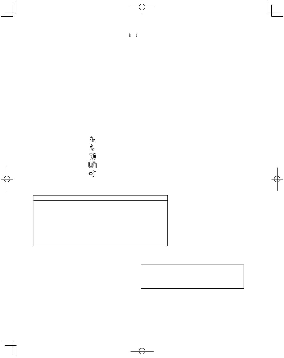
Table 1-13 Indoor Unit Tubing Connection Size ( 1 – 40) |
|
|
|
in. (mm) |
||||||
|
|
|
|
|
|
|
|
|
|
|
|
|
|
|
|
|
|
|
|
|
|
Indoor unit type |
7 |
9 |
|
12 |
18 |
24 |
36 |
48 |
||
Total system horsepower |
0.8 |
1 |
|
1.3 |
2 |
3 |
4 |
5 |
||
Distribution |
Suction tubing |
|
|
|
|
ø5/8" |
|
|
|
|
|
|
|
|
(ø15.88) |
|
|
|
|
||
joint – |
|
|
|
|
|
|
|
|
|
|
Discharge tubing |
|
|
|
|
ø1/2" |
|
|
|
|
|
solenoid valve |
|
|
|
|
(ø12.70) |
|
|
|
|
|
kit tubing |
Liquid tubing |
|
|
|
|
ø3/8" |
|
|
|
|
|
|
|
|
|
(ø9.52) |
|
|
|
|
|
|
|
|
|
|
|
|
|
|
|
|
Solenoid valve |
Gas tubing |
|
|
ø1/2" |
|
|
|
ø5/8" |
|
|
kit – Indoor |
|
|
(ø12.70) |
|
|
|
(ø15.88) |
|
||
|
|
|
|
|
|
|
|
|
|
|
unit tubing |
|
|
|
|
|
|
|
|
|
|
Liquid tubing |
|
|
ø1/4" |
|
|
|
ø3/8" |
|
||
connection |
|
|
|
|
|
|
||||
|
|
(ø6.35) |
|
|
|
(ø9.52) |
|
|||
|
|
|
|
|
|
|
|
|||
|
|
|
|
|
|
|
|
|
|
|
*1: For the solenoid valve kits, use type 160 with parallel specifications. Branch the tubing before and after the solenoid valve kits.
1-7. Straight Equivalent Length of Joints
Design the tubing system by referring to the following table for the straight equivalent length of joints.
Table 1-14 Straight Equivalent Length of Joints
Gas tubing size (in.(mm)) |
1/2" |
5/8" |
3/4" |
7/8" |
1" |
1-1/8" |
1-1/4" |
1-1/2" |
||||
(12.7) |
(15.88) |
(19.05) |
(22.22) |
(25.4) |
(28.58) |
(31.8) |
(38.1) |
|||||
|
|
|
|
|||||||||
|
|
|
|
|
|
|
|
|
|
|
|
|
|
|
|
|
1 ft. |
1.1 ft. |
1.4 ft. |
1.6 ft. |
1.7 ft. |
1.9 ft. |
2.3 ft. |
2.6 ft. |
|
90ooelbow |
|
|||||||||||
|
(0.30 m) |
(0.35 m) |
(0.42 m) |
(0.48 m) |
(0.52 m) |
(0.57 m) |
(0.70m) |
(0.79 m) |
||||
|
|
|
|
|||||||||
|
|
|
|
|
|
|
|
|
|
|
|
|
45ooelbow |
0.8 ft. |
0.9 ft. |
1 ft. |
1.2 ft. |
1.3 ft. |
1.4 ft. |
1.7 ft. |
1.9 ft. |
||||
(0.23 m) |
(0.26 m) |
(0.32 m) |
(0.36 m) |
(0.39 m) |
(0.43 m) |
(0.53 m) |
(0.59 m) |
|||||
|
|
|
|
|||||||||
U-shape tube bent |
3 ft. |
3.4 ft. |
4.1 ft. |
4.7 ft. |
5.1 ft. |
5.6 ft. |
6.9 ft. |
7.8 ft. |
||||
(R2–23/64–3–15/16 in.) |
(0.90 m) |
(1.05 m) |
(1.26 m) |
(1.44 m) |
(1.56 m) |
(1.71 m) |
(2.10 m) |
(2.37 m) |
||||
|
|
|
|
|
|
|
|
|
|
|
|
|
Trap bend |
7.5 ft. |
9.2 ft. |
10.5 ft. |
12.5 ft. |
14.1 ft. |
15.4 ft. |
16.4 ft. |
14.0 ft. |
||||
(2.30 m) |
(2.80 m) |
(3.20 m) |
(3.80 m) |
(4.30 m) |
(4.70 m) |
(5.00 m) |
(5.80 m) |
|||||
|
|
|
|
|||||||||
Y-branch distribution joint |
|
|
Equivalent length conversion not needed. |
|
||||||||
|
|
|
|
|
|
|
|
|||||
Ball valve for service |
|
|
Equivalent length conversion not needed. |
|
||||||||
|
|
|
|
|
|
|
|
|
|
|
|
|
Table 1-15 Refrigerant tubing (Existing tubing can be used.)
Tubing size (in. (mm))
Material O |
|
Material 1/2H • H |
||
|
|
|
|
|
ø1/4" (ø6.35) |
|
t1/32 (t0.8) |
|
|
|
|
|
|
|
ø3/8" (ø9.52) |
|
t1/32 (t0.8) |
ø1-1/8" (ø28.58) |
t5/128 (t1.0) |
|
|
|
|
|
ø1/2" (ø12.7) |
|
t1/32 (t0.8) |
ø1-1/4" (ø31.75) |
t3/64 (t1.1) |
|
|
|
|
|
ø5/8" (ø15.88) |
|
t5/128 (t1.0) |
ø1-1/2" (ø38.10) |
over t3/64 (t1.15) |
|
|
|
|
|
ø3/4" (ø19.05) |
over t5/128 (t1.0) |
ø1-5/8" (ø41.28) |
over t3/64 (t1.20) |
|
|
|
|
|
|
ø7/8" (ø22.22) |
|
t5/128 (t1.0) |
|
|
|
|
|
|
|
1-8. Additional Refrigerant Charge
*When bending the tubes, use a bending radius that is at least 4 times the outer diameter of the tubes.
In addition, take sufficient care to avoid crushing or damaging the tubes when bending them.
Additional refrigerant charge amount is calculated from the liquid tubing total length as follows.
Table 1-16-1 Amount of Refrigerant Charge Per ft., According to Liquid Tubing Size
Liquid tubing |
ø1/4" |
ø3/8" |
ø1/2" |
ø5/8" |
ø3/4" |
ø7/8" |
size |
(ø6.35) |
(ø9.52) |
(ø12.7) |
(ø15.88) |
(ø19.05) |
(ø22.22) |
Amount of |
|
|
|
|
|
|
refrigerant |
0.279 |
0.602 |
1.38 |
1.99 |
2.78 |
3.93 |
charge (oz/ft.) |
|
|
|
|
|
|
Table 1-16-2 Necessary Amount of Refrigerant
Charge Per Unit
CHDZ09053 |
CHDZ14053 |
CHDZR09053 |
CHDZR14053 |
— |
113 oz/unit |
Required amount of charge = Necessary Amount of Refrigerant Charge Per Unit (14053 Type) + (Amount of refrigerant charge per ft. of each size of liquid tube
×its tube length) + (...) + (...)
*Always charge accurately using a scale for weighing.
13
W-3WAY_ECO-i_US.indd 13 |
2008/02/15 12:29:03 |
|
|
|
|
|
|
||
|
|
|
||
|
|
|
|
|
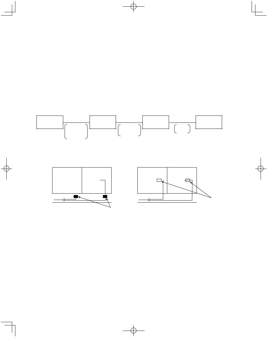
Table 1-17 Refrigerant Charge Amount at Shipment (for outdoor unit)
DC |
CHDZ09053 |
CHDZ14053 |
|
CHDZR09053 |
CHDZR14053 |
||
(oz) |
|||
|
|
||
416 |
416 |
||
|
|||
|
|
|
1-9. System Limitations
Table 1-18 System Limitations
Max. No. allowable connected outdoor units |
2 |
|
|
Max. capacity allowable connected outdoor units |
307,100 BTU/h (32 hp, 90 kw) |
|
|
Max. connectable indoor units |
40 *1 |
Max. allowable indoor/outdoor capacity ratio |
50 – 130 % |
|
|
*1: In the case of 20 hp (type 191.100 BTU/h) or smaller units, the number is limited by the total capacity of the connected indoor units.
1-10. Installation Standards
Relationship between A/C units and refrigerant tubing
Outdoor unit |
4-tube layout |
Outdoor unit |
3-tube layout |
Solenoid |
2-tube layout |
Indoor unit |
|
|
valve kit |
|
|||
|
Suction tube |
|
Suction tube |
Gas tube |
|
|
|
|
|
|
|||
|
Discharge tube |
|
Discharge tube |
|
Liquid tube |
|
|
Liquid tube |
|
Liquid tube |
|
|
|
|
Balance tube |
|
|
|
|
|
●Install the solenoid valve kit 98 ft. or less from the indoor unit.
●In quiet locations such as hospitals, libraries, and hotel rooms, the refrigerant noise may be somewhat noticeable. It is recommended that the solenoid valve kit be installed inside the corridor ceiling, at a location outside the room.
Room |
|
Room |
NO |
Room |
|
Room |
||||||||||||
Indoor unit |
|
Indoor unit |
Indoor unit |
|
Indoor unit |
|||||||||||||
|
|
|
||||||||||||||||
YES |
|
|
|
|
|
|
|
|
|
|
|
|
|
|
|
|
|
|
|
|
|
|
|
|
|
|
|
|
|
|
|
|
|
|
|
|
|
|
|
|
|
|
|
|
|
|
|
|
|
|
|
|
|
|
|
|
Hallway |
|
|
|
|
|
|
|
Hallway |
|
|
|
|
|
|||||
|
|
|
|
|
|
|
|
|
|
|
|
|||||||
Solenoid valve kit
Solenoid valve kit
Common solenoid valve kit
● Multiple indoor units under group control can utilize a solenoid valve kit in common.
● Categories of connected indoor unit capacities are determined by the solenoid valve kit.
Type of solenoid valve kit |
Total capacity of indoor units (BTU/h) |
|
|
160 |
19.000 < Total capacity < 54.600 |
|
|
56 |
7.500 < Total capacity < 19.000 |
|
|
● If the capacity range is exceeded, use 2 solenoid valves connected in parallel.
14
W-3WAY_ECO-i_US.indd 14 |
2008/02/07 10:55:40 |
|
|
|
|
|
|
||
|
|
|
||
|
|
|
|
|
Always check the gas density
WARNING limit for the room in which the unit is installed.
1-11. Check of Limit Density
When installing an air conditioner in a room, it is necessary to ensure that even if the refrigerant gas accidentally leaks out, its density does not exceed the limit level for that room. If the density could exceed the limit level, it is necessary to provide an opening between the unit and the adjacent room, or to install mechanical ventilation which is interlocked with a leak detector.
(Total refrigerant charged amount: oz)
(Min. indoor volume where the indoor unit is installed: ft.3) < Limit density 0.3 (oz/ft.3)
The limit density of refrigerant which is used in this unit is 0.3 oz/ft.3 (ISO 5149).
The shipped outdoor unit comes charged with the amount of refrigerant fixed for each type, so add it to the amount that is charged in the field. (For the refrigerant charge amount at shipment, refer to the unit’s nameplate.)
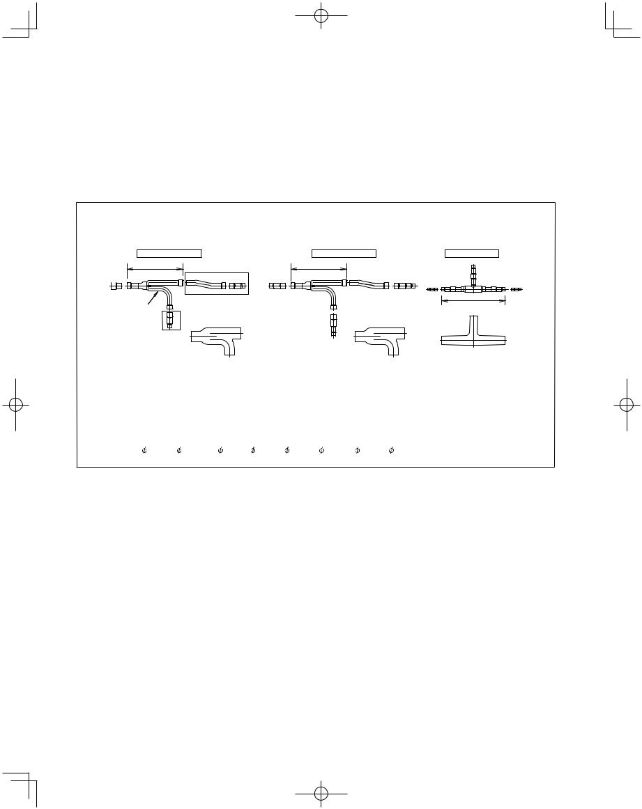
1-12. Installing Distribution Joint
Pay special attention to any
CAUTION location, such as a basement, etc., where leaking refrigerant
can accumulate, since refrigerant gas is heavier than air.
(1)Refer to “HOW TO ATTACH DISTRIBUTION JOINT” enclosed with the optional distribution joint kit (APR-CHRZP900BAB, RZP224BAB, RZP680BAB, RZP1350BAB).
(2)When creating a branch using a commercially available T-joint (header joint system), orient the main tubing so that it is either horizontal (level) or vertical. In order to prevent accumulation of refrigerant oil in stopped units, if the main tubing is horizontal then each branch tubing length should be at an angle that is greater than horizontal. If the main tubing is vertical, provide a raised starting portion for each branch.
[Header joint system]
●Be sure to solidly weld shut the T-joint end (marked by “X” in the figure). In addition, pay attention to the insertion depth of each connected tube so that the flow of refrigerant within the T-joint is not impeded.
●When using the header joint system, do not make further branches in the tubing.
●Do not use the header joint system on the outdoor unit side.
(3)If there are height differences between indoor units or if branch tubing that follows a distribution joint is connected to only 1 unit, a trap or ball valve must be added to that distribution joint. (When adding the ball valve, locate it within 15 - 3/4" of the distribution joint.)
If a trap or ball valve is not added, do not operate the system before repairs to a malfunctioning unit are completed. (The refrigerant oil sent through the
15
tubing to the malfunctioning unit will accumulate and may damage the compressor.)
Minimum indoor volume & floor area as against the amount of refrigerant is roughly as given in the following table.
|
ft.3 |
|
|
|
|
|
|
|
|
|
|
|
|
|
ft.2 |
|
|
|
|
10000 |
|
|
|
|
|
|
|
|
|
|
|
|
|
|
1136 |
|
|
indoorMin.volume |
9500 |
|
|
|
|
|
|
|
|
|
|
|
|
|
|
1079 |
indoorMin.floor area |
ceilingthe(whenis 8.8 ft. high) |
|
|
|
|
|
the density |
limit of |
|
|
||||||||||
2000 |
|
|
|
|
|
|
|
227 |
||||||||||
|
9000 |
|
Range below |
|
|
|
|
|
|
|
|
|
1022 |
|
|
|||
|
8500 |
|
the density limit of |
|
|
|
|
|
|
|
966 |
|
|
|||||
|
8000 |
|
0.3 oz/ft.3 |
|
|
|
|
|
|
|
|
|
909 |
|
|
|||
|
7500 |
|
|
|
|
|
|
|
|
|
|
852 |
|
|
||||
|
7000 |
|
(countermeasures |
|
|
|
|
|
|
|
795 |
|
|
|||||
|
6500 |
|
not needed) |
|
|
|
|
|
|
|
|
|
738 |
|
|
|||
|
6000 |
|
|
|
|
|
|
|
|
|
|
|
|
|
|
682 |
|
|
|
5500 |
|
|
|
|
|
|
|
|
|
|
|
|
|
|
625 |
|
|
|
5000 |
|
|
|
|
|
|
|
|
|
|
|
|
|
|
568 |
|
|
|
|
|
|
|
|
|
|
|
|
|
|
|
|
|
|
|
||
|
4500 |
|
|
|
|
|
|
|
|
|
|
|
|
|
|
511 |
|
|
|
|
|
|
|
|
|
|
|
|
|
|
|
|
|
|
|
||
|
4000 |
|
|
|
|
|
|
|
|
|
|
|
|
|
|
454 |
|
|
|
|
|
|
|
|
|
|
|
|
|
|
|
|
|
|
|
||
|
3500 |
|
|
|
|
|
|
|
|
|
|
|
|
|
|
398 |
|
|
|
|
|
|
|
|
|
|
|
|
|
|
|
|
|
|
|
||
|
3000 |
|
|
|
|
|
Range above |
|
|
|
|
|
341 |
|
|
|||
|
|
|
|
|
|
|
|
|
|
|
|
|
||||||
|
2500 |
|
|
|
|
|
|
|
|
|
|
284 |
|
|
||||
|
|
|
|
|
|
0.3 oz/ft.3 |
|
|
|
|
|
|
|
|||||
|
1500 |
|
|
|
|
|
|
|
|
|
|
170 |
|
|
||||
|
|
|
|
|
|
|
|
|
|
|
|
|
||||||
|
|
|
|
|
|
|
|
|
|
|
|
|
||||||
|
1000 |
|
|
|
|
|
(countermeasures |
|
|
114 |
|
|
||||||
|
|
|
|
|
|
|
|
|
|
|||||||||
|
500 |
|
|
|
|
|
needed) |
|
|
|
|
|
57 |
|
|
|||
|
|
|
|
|
|
|
|
|
|
|
|
|
||||||
|
0 |
|
|
|
|
|
|
|
|
|
|
|
|
|
|
0 |
|
|
|
|
|
|
|
|
|
|
|
|
|
|
|
|
|
|
|
||
|
0 |
500 |
1000 |
1500 |
2000 |
2500 |
3000 |
|
|
|||||||||
|
|
|
|
|
|
|
|
|
|
|
|
|
|
|
|
oz |
|
|
Total amount of refrigerant
Tube branching methods (horizontal use)
|
to |
30 |
15 |
|
|
|
|
|
|
|
|
|
B |
|
|
|
A |
Horizontal |
A |
||
|
B |
line |
View as seen |
|||
|
|
|||||
|
|
|
||||
|
|
|
|
from arrow |
||
|
|
Arrow view |
|
|
||
Header joint system (Indoor) |
||||||
|
|
Install at a |
|
|
|
|
|
|
positive angle |
|
|
||
Outdoor |
|
Indoor |
|
|
|
|
|
|
|
|
|
||
|
|
|
|
|
Install at a |
|
Indoor |
|
|
|
|
positive angle |
|
|
|
|
|
(15 – 30°) |
||
|
|
|
|
|
||
Horizontal |
|
|
|
|
||
line |
|
|
|
|
|
|
|
|
Indoor |
|
|
|
|
L3 |
6.56 ft. |
Horizontal |
Solidly welded |
|||
|
|
line |
|
shut (X) |
||
|
|
|
|
|||
Types of vertical trap specifications |
||||||
(When using ball valve) |
|
|
||||
Main tubing |
|
|
|
|
||
Ball valve |
Indoor unit (more than 2 units) |
|||||
(If only 1 unit is connected, a ball valve |
||||||
(BV: purchased |
||||||
separately) |
is also needed on this side.) |
|||||
Indoor unit (1) |
|
|
|
|
||
(When not using ball valve) |
|
|||||
Main tubing |
|
Horizontal |
|
|
||
|
|
|
|
|||
|
|
Indoor unit |
(Each unit is connected |
|||
Branch tubing is |
|
to tubing that is either |
||||
|
level or is directed |
|||||
directed upward. |
|
|||||
|
downward.) |
|||||
|
More than |
|
||||
|
|
|
|
|||
|
7–7/8" |
|
|
|
||
Indoor unit is directed downward |
|
|
|
|||
W-3WAY_ECO-i_US.indd 15 |
2008/02/07 10:55:40 |
|
|
|
|
|
|
||
|
|
|
||
|
|
|
|
|
1-13. Optional Distribution Joint Kits
See the installation instructions packaged with the distribution joint kit for the installation procedure.
Table 1-19
Model name |
Cooling capacity after distribution |
Remarks |
|
|
|
|
|
1. APR-CHRZP900BAB |
307.100 |
BTU/h or less |
For outdoor unit |
|
|
|
|
2. APR-RZP224BAB |
76.400 |
BTU/h or less |
For indoor unit |
|
|
|
|
3. APR-RZP680BAB |
232.000 |
BTU/h or less |
For indoor unit |
|
|
|
|
4. APR-RZP1350BAB |
460.700 |
BTU/h or less |
For indoor unit |
|
|
|
|
■Tubing size (with thermal insulation)
1.APR-CHRZP900BAB
For outdoor unit (Capacity after distribution joint is 307.100 BTU/h or less.)
Note that the dimension marked with every alphabetical letter in the diagram shows the inner diameter.
Suction Tube |
|
|
Discharge Tube |
|
|
Liquid Tube |
||||
11-13/16 |
|
|
|
11-13/16 |
|
|
|
|
G |
|
|
#C |
|
|
#C |
|
|
|
|
F |
|
B C |
C D E |
E D C |
C |
D E F |
I H |
GF E |
E |
|||
|
||||||||||
|
|
|
|
|
|
|
E FG H I |
|||
|
#C |
|
|
|
|
|
|
|
13-25/64 |
|
Distribution |
|
|
#C |
|
|
|
|
|
||
Joint |
D |
|
|
|
|
|
|
|
|
|
|
|
|
D |
|
|
|
|
|
||
|
E |
|
|
E |
|
|
|
|
|
|
|
|
|
|
F |
|
|
|
|
|
|
|
|
Insulation |
|
|
Insulation |
|
|
|
Insulation |
|
*Insulators for both the Suction tube and the Discharge tube are the same.
*Suction tube and Discharge tube are similar in sizes and both the tube entrances have the same diameter. So the both Distribution joints can fit into different tubes. Since the diameter of the tube ends for both Suction and Discharge tube are different, take care not to connect the distribution joint different. See the " # " marks on the above figures.
Table 1-20 Dimensions for connections of each part
Size |
Part B |
Part C |
Part D |
Part E |
Part F |
Part G |
Part H |
Part I |
Inch |
1-1/4 |
1-1/8 |
1 |
7/8 |
3/4 |
5/8 |
1/2 |
3/8 |
16
W-3WAY_ECO-i_US.indd 16 |
2008/02/07 10:55:40 |
|
|
|
|
|
|
||
|
|
|
||
|
|
|
|
|
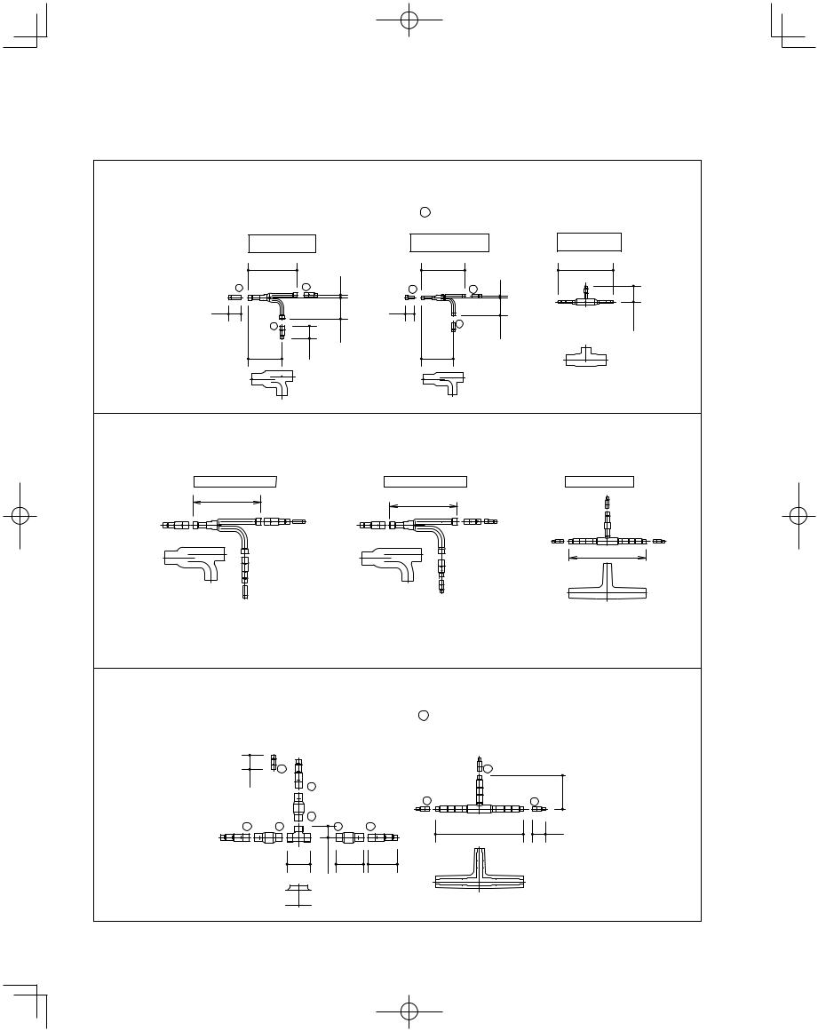
Table 1-21 Dimensions for connections of each part |
|
|
|
|
Unit: in. |
|||||
|
|
|
|
|
|
|
|
|
|
|
Position |
A |
B |
C |
D |
E |
F |
G |
H |
I |
J |
Dimension |
ø1-1/2" |
ø1-1/4" |
ø1-1/8" |
ø1" |
ø7/8" |
ø3/4" |
ø5/8" |
ø1/2" |
ø3/8" |
– |
|
|
|
|
|
|
|
|
|
|
|
2.APR-RZP224BAB
Use: For indoor unit (Capacity after distribution joint is 76.400 BTU/h or less.)
Example: (F below indicates inner diameter. F below indicates outer diameter.)
Suction tubing
|
|
|
8–17/64 |
|
|
G |
F |
F |
F |
F |
15/32 |
|
|
|
|
|
|
2–11/64 |
|
|
|
G H |
|
|
|
F |
|
|
|
|
|
|
|
3–5/8 |
|
|
|
|
F |
|
|
|
|
|
G |
|
|
|
|
|
H |
2–11/64 |
|
|
|
|
5–45/64 |
||
|
|
|
|
Discharge tubing
|
7–21/64 |
|
|
|
G H |
H |
H |
H G |
9/32 |
1–37/64 |
|
H |
|
|
|
|
|
3–1/32 |
|
|
|
H |
|
|
|
|
G |
|
|
|
|
|
|
|
|
5–23/64 |
|
|
|
Thermal insulation |
Thermal insulation |
|
Liquid tubing |
|
||
|
|
9–1/4 |
|
|
|
|
I |
|
|
|
|
H |
2–23/32 |
|
I |
H |
H I |
||
|
||||
Thermal insulation
Unit: in.
3.APR-RZP680BAB
Use: For indoor unit (Capacity after distribution joint is greater than 76.400 BTU/h and no more than 232.000 BTU/h.)
Note that the dimension marked with every alphabetical letter in the diagram shows the inner diameter.
Suction Tube |
|
Discharge Tube |
Liquid Tube |
|
|||
11-13/16 |
|
|
11-13/16 |
|
|
I |
|
|
#C |
|
|
|
H |
|
|
F E D C |
DE F G |
F E D C |
#D E F GH |
|
G |
|
|
|
|
F |
|
||||
|
|
|
|
I H |
GFE |
E |
E FG H I |
|
|
|
|
|
|||
|
#C |
|
|
#D |
|
13-25/64 |
|
|
D |
|
|
E |
|
|
|
|
E |
|
|
F |
|
|
|
Insulation |
F |
|
Insulation |
G |
|
|
|
G |
|
H |
|
|
|
||
*Insulators for both the Suction tube and the Discharge tube are the same.  *Suction tube and Discharge tube are similar in sizes and both the tube entrances have the same diameter. So the both Distribution joints can fit into different tubes. Since the diameter of the tube ends for both Suction and Discharge tube are different, take care not to connect the distribution joint different. See the " # " marks on the above figures.
4.APR-RZP1350BAB
Use: For indoor unit (Capacity after distribution joint is greater than 232.000 BTU/h and no more than 460.700 BTU/h.)
Example: (B below indicates inner diameter. B below indicates outer diameter.)
Suction tubing • Discharge tubing |
|
Liquid tubing |
|
|
|
H |
F |
|
G |
||
E |
||
F |
||
2–11/64 |
D |
|
|
||
|
C |
|
|
C |
|
|
A |
|
|
B |
|
F E D C C A B |
B |
|
B |
B |
|
3–35/64 |
||
Thermal insulation 
1–49/64
|
I |
|
|
|
|
H |
G |
|
|
|
|
|
|
|
|
G |
F |
|
5–1/8 |
|
|
|
||
G G F E |
|
E |
|
|
|
|
|
||
|
E F G |
G |
|
|
I H |
|
|
H I |
|
B A C |
C D E F |
13–25/64 |
1–31/32 |
|
|
||
4–9/64 |
4–13/32 |
|
|
Thermal insulation Unit: in.
17
W-3WAY_ECO-i_US.indd 17 |
2008/02/07 10:55:40 |
|
|
|
|
|
|
||
|
|
|
||
|
|
|
|
|
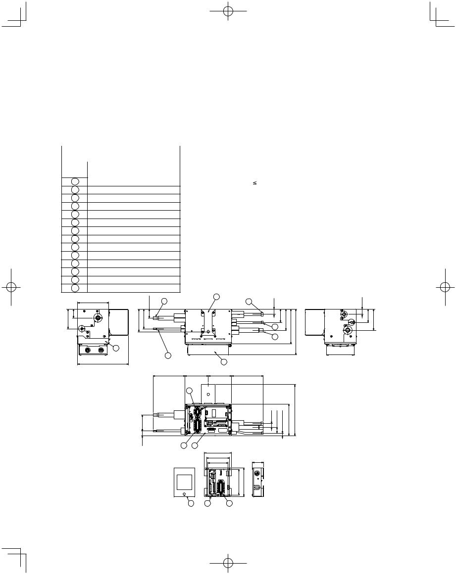
1-14. Optional Solenoid Valve Kit
Precautions on Installation of Solenoid Valve Kit
(1)Clean base metals thoroughly.
(2)Use proper ventilation to carry fumes away from the work area.
(3)Use a high quality silver based solder of at least 15 % silver.
(4)Heat the base materials broadly and uniformly.
(5)Take precautions not to overheat the device which could damage sensitive internal components.
(6)Insure compliance with all local codes!
|
ATK-RZP56BAWB |
|
|
Part |
Types and specifications of |
Number |
tubing connections |
1Gas tube: ID1/2"
2Liquid tube : ID1/4"
3Suspension hook
4Liquid tube : ID3/8"
5Suction tube: ID5/8"
6Discharge tube: ID1/2"
7Service panel
8Base of control box
9Terminal for power line
10Terminal for communication line
11Earth (M5 with washer)
12Cover of control box
13Relay kit
14Cover of relay kit
|
5-25/32 |
21/32-1 |
1 |
|
|
||
|
|
|
|
3-21/32 1-21/32 |
|
4-7/32 3-21/32 |
|
7
2
9-13/32
5-55/64
53/64 2-63/64
 Specifications
|
ATK-RZP56BAWB |
|
|
Compatibility |
7.500 Total capacity of indoor units (BTU/h) < 19.000 |
Power source |
Single-phase 200V 50/60Hz (supplied by indoor unit) |
Power input |
20 W |
Net weight |
151.7 oz. |
Accessories |
Washer x 2 |
|
Insulating tape |
|
|
3 |
6 |
63/64 |
|
|
63/64 |
|
|
|
|||
|
|
15/16-3 |
29/64-6 15/32-8 |
2-31/64 15/16-3 |
|
|
|
2-31/64 |
|||
|
|
4 |
|
|
|
|
|
5 |
|
|
|
12
4-21/64 4-21/64 5-55/64
9
43/64 1-7/64 7/16 5-55/64 9-29/64
11 |
8 |
|
|
5-3/64 |
|
|
4-1/4 |
2-3/64 |
|
3-25/32 |
|
|
4-49/64 |
5-9/32 |
|
|
Unit: in. |
14 13 10
18
W-3WAY_ECO-i_US.indd 18 |
2008/02/07 10:55:41 |
|
|
|
|
|
|
||
|
|
|
||
|
|
|
|
|
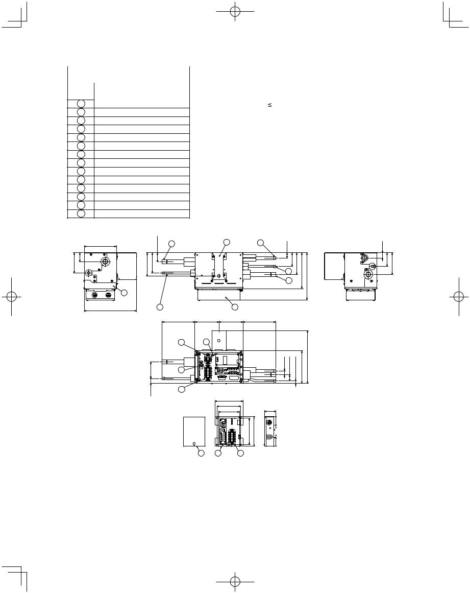
|
ATK-RZP160BAWB |
|
|
Part |
Types and specifications of |
Number |
tubing connections |
1Gas tube: ID5/8"
2Liquid tube : ID3/8"
3Suspension hook
4Liquid tube : ID3/8"
5Suction tube: ID5/8"
6Discharge tube: ID1/2"
7Service panel
8Base of control box
9Terminal for power line
10Terminal for communication line
11Earth (M5 with washer)
12Cover of control box
13Relay kit
14Cover of relay kit
 Specifications
|
ATK-RZP160BAWB |
|
|
Compatibility |
19.000 Total capacity of indoor units (BTU/h) < 54.600 |
Power source |
Single-phase 200V 50/60Hz (supplied by indoor unit) |
Power input |
25 W |
Net weight |
165.8 oz. |
Accessories |
Washer x 2 |
|
Insulating tape |
|
|
5-25/32 |
|
21/32-1 |
1 |
3 |
6 |
63/64 |
|
|
|
|
|
|
|
|
|
||||
3-21/32 1-21/32 |
4-7/32 3-21/32 |
|
|
|
|
31/64-2 |
6-29/64 |
15/32-8 |
|
|
|
|
|
5 |
15/163- |
||||
|
|
|
|
|
|
4 |
|
|
|
|
7 |
|
|
|
|
|
|
|
|
9-13/32 |
|
|
2 |
12 |
|
|
|
|
|
|
|
|
5-55/64 |
4-21/64 4-21/64 |
5-55/64 |
|
|
|
|
|
|
|
9 |
8 |
|
|
|
|
|
|
63/64-2 |
|
11 |
|
|
43/64 1-7/64 |
7/16 |
5-55/64 |
9-29/64 |
|
|
|
|
|
|
|
|
|
|
|
53/64 |
|
10 |
|
|
|
|
|
|
|
|
|
|
|
|
|
|
|
|
|
|
|
|
5-3/64 |
|
|
|
|
|
|
|
|
|
4-1/4 |
2-3/64 |
|
|
|
|
|
|
|
|
3-25/32 |
|
|
|
|
|
|
|
|
|
4-49/64 |
5-9/32 |
|
|
|
|
14 13 10
19
63/64 2-31/64 3-15/16
Unit: in.
W-3WAY_ECO-i_US.indd 19 |
2008/02/07 10:55:41 |
|
|
|
|
|
|
||
|
|
|
||
|
|
|
|
|
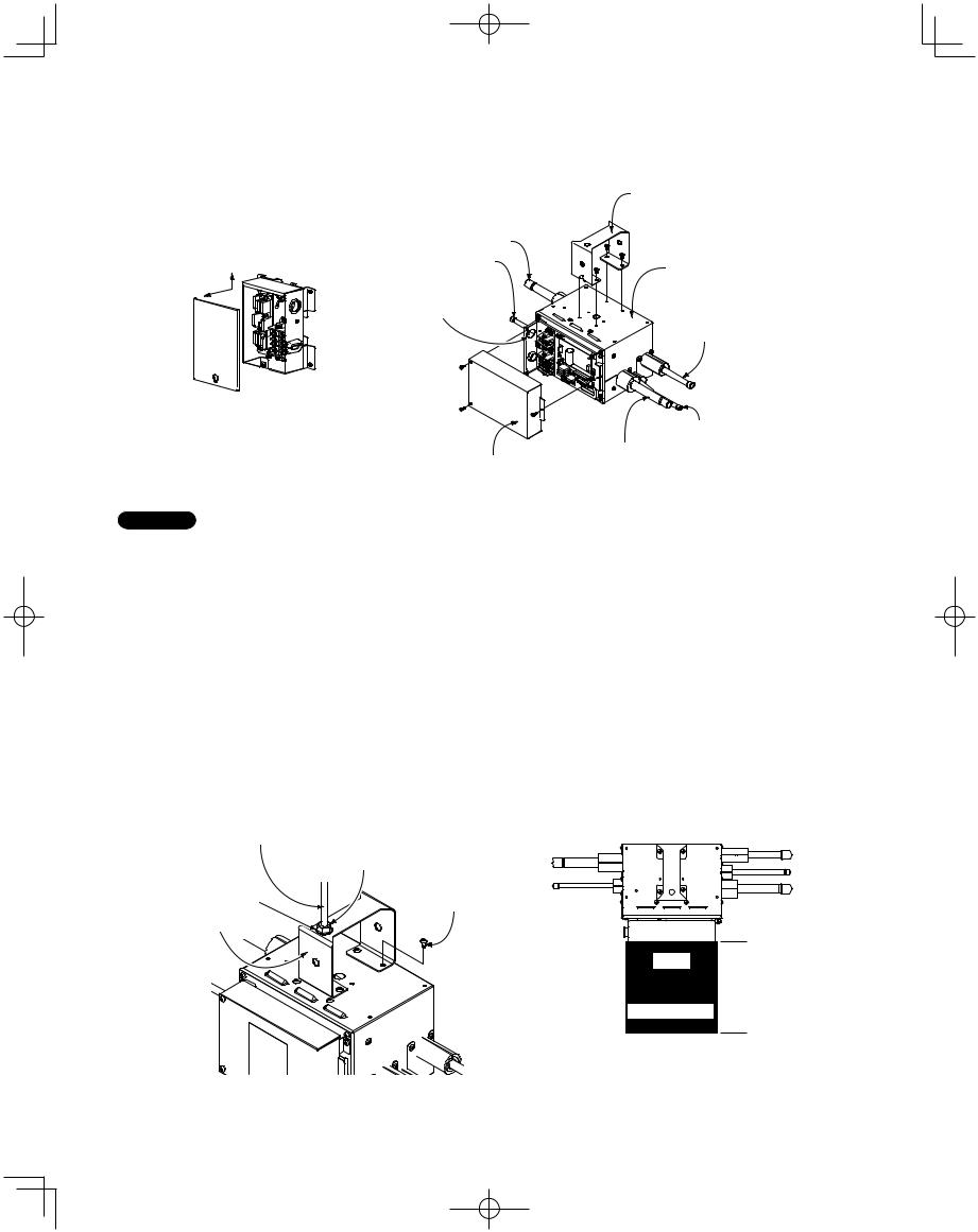
Installation of Solenoid Valve Kit
1.Install the relay kit into the indoor unit.
Refer to the Installation Manual for the solenoid valve kit.
2.Connect the solenoid valve kit and the relay kit in the field.
Gas tube Liquid tube
Connect with conduit for power supply
Relay kit |
Front |
|
Cover of control box
Suspension hook
Top surface
Discharge tube
Liquid tube Suction tube
NOTE
Notes on Installation
•Be sure to secure the valve body by using its structure with the suspension bolt, etc.
•Install the valve body within a distance of 98 ft. from the indoor unit.
Some refrigerant noise will be produced. Therefore in hospitals, libraries, hotel guest rooms, and other quiet locations, it is recommended that the solenoid valve kit be installed on the ceiling reverse side of a hallway or another location separated from the room.
•When installing the valve body, install with the top surface facing up. Secure 7-7/8" or more of space to the front so that the front service panel can be removed.
•If the supplied suspension hook will not be used, and other fastening devices will be attached in the field, use the 4 screw holes on the top surface. DO NOT use any long screws other than the supplied screws. Use of other screws may puncture the internal tubing, resulting in refrigerant leakage.
•Do not block the air holes.
Suspension bolt (3/8" or M10) (field supplied)
Nut (field supplied) (3/8" or M10)
Washer |
M4 screws |
|
(12 pcs.) |
Suspension hook |
|
Front
Service space
7-7/8" or more
20
W-3WAY_ECO-i_US.indd 20 |
2008/02/07 10:55:41 |
|
|
|
|
|
|
||
|
|
|
||
|
|
|
|
|
1-15. Example of Tubing Size Selection and Refrigerant Charge Amount
Additional refrigerant charging
Based on the values in Tables 1-10, 11, 12, 15 and 16-2 use the liquid tubing size and length, and calculate the amount of additional refrigerant charge using the formula below.
= Necessary Amount of Refrigerant Charge Per Unit + 3.93 × (a) + 2.78 × (b) + 1.99 × (c) + 1.38 × (d) + 0.602 × (e) + 0.279 × (f)
(a) : Liquid tubing |
Total length of ø7/8" (ft.) |
(d) : Liquid tubing |
Total length of ø1/2" (ft.) |
(b) : Liquid tubing |
Total length of ø3/4" (ft.) |
(e) : Liquid tubing |
Total length of ø3/8" (ft.) |
(c) : Liquid tubing |
Total length of ø5/8" (ft.) |
(f) : Liquid tubing |
Total length of ø1/4" (ft.) |
●Charging procedure
Be sure to charge with R410A refrigerant in liquid form.
1.After performing a vacuum, charge with refrigerant from the liquid tubing side. At this time, all valves must be in the “fully closed” position.
2.If it was not possible to charge the designated amount, operate the system in Cooling mode while charging with refrigerant from the gas tubing side. (This is performed at the time of the test run. For this, all valves must be in the “fully open” position. However if only one outdoor unit is installed, a balance tube is not used. Therefore, leave the valves fully closed.)
Charge with R410A refrigerant in liquid form.
With R410A refrigerant, charge while adjusting the amount being fed a little at a time in order to prevent liquid refrigerant from backing up.
●After charging is completed, turn all valves to the “fully open” position.
●Replace the tubing covers as they were before.
1.R410A additional charging absolutely must Balance tube
be done through liquid charging.
CAUTION
2. The R410A refrigerant cylinder has a gray base color, and the top part is pink.
3. The R410A refrigerant cylinder includes a siphon tube. Check that the siphon tube is present. (This is indicated on the label at the top of the cylinder.)
4. Due to differences in the refrigerant, pressure, and refrigerant oil involved in installation, it is not possible in some cases to
use the same tools for R22 and for R410A.
Example:
Outdoor unit
09053 09053 model model
Use a flathead screwdriver and open by turning the part with the screw groove to the right, from " " to " "
Liquid tube
Use a hex wrench (width 5/32 inch) and turn to the left to open.
Discharge tube
Use a flathead screwdriver and open by turning the part with the screw groove to the right, from " " to " "
Suction tube
Use a flathead screwdriver and open by turning the part with the screw groove to the right, from " " to " "
B |
|
|
A |
|
|
|
|
|
|
|
LC |
|
|
|
|
|
|
|
|
|
|
|
|||||||||||
|
|
|
|
|
|
|
|
|
|
|
LB |
|
|
|
|
|
|
|
|
|
|
|
|
|
|
|
|
|
|
||||
|
|
|
|
|
|
|
|
|
|
|
|
|
|
||||||||||||||||||||
|
|
|
|
|
|
|
|
|
|
|
|
|
|
|
|
|
|
|
|
|
|
|
|
|
|
|
|
|
|
|
|
|
|
|
|
|
|
LA |
|
|
|
|
2 |
|
|
|
3 |
|
|
|
|
4 |
|
||||||||||||||
|
|
1 |
|
|
|
|
|
|
|
|
|
||||||||||||||||||||||
|
|
|
|
|
|
|
|
|
|
|
|
|
|
|
|
|
|
|
|
|
|
|
|
|
|
|
|
||||||
|
|
|
|
|
|
|
|
|
|
|
|
|
|
|
|
|
|
|
|
|
|
|
|
|
|
|
|
|
|||||
|
|
|
|
|
|
|
|
|
|
|
|
|
|
|
|
|
|
|
|
|
|
|
|
|
|
|
|||||||
|
|
|
|
|
|
|
|
48 model 48 model |
|
48 model |
36 model |
||||||||||||||||||||||
● Example of each tubing length |
|
|
|
|
|
|
|
|
|
|
|
|
|
|
|
|
|
|
|
|
|
|
|||||||||||
Main tubing |
|
|
|
|
|
|
|
|
|
|
Distribution joint tubing |
|
|
|
|||||||||||||||||||
LA = 131 ft. |
|
|
|
|
|
|
|
|
|
|
Outdoor side |
|
|
|
|
|
|
|
|
|
Indoor side |
||||||||||||
LB = 16 ft. |
|
|
|
|
|
|
|
|
|
|
|
|
A = 7 ft. |
|
|
|
|
|
|
|
|
|
1 = 98 ft. |
||||||||||
LC = 16 ft. |
|
|
|
|
|
|
|
|
|
|
|
|
B = 7 ft. |
|
|
|
|
|
|
|
|
|
2 = 16 ft. |
||||||||||
|
|
|
|
|
|
|
|
|
|
|
|
|
|
|
|
|
|
|
|
|
|
|
|
|
|
|
|
|
|
|
|
3 = 16 ft. |
|
|
|
|
|
|
|
|
|
|
|
|
|
|
|
|
|
|
|
|
|
|
|
|
|
|
|
|
|
|
|
|
|
4 = 65 ft. |
|
|
|
|
|
|
|
|
|
|
|
|
|
|
|
|
|
|
|
|
|
|
|
|
21 |
|
|
|
|
||||||
W-3WAY_ECO-i_US.indd 21 |
2008/02/15 13:01:02 |
|
|
|
|
|
|
||
|
|
|
||
|
|
|
|
|
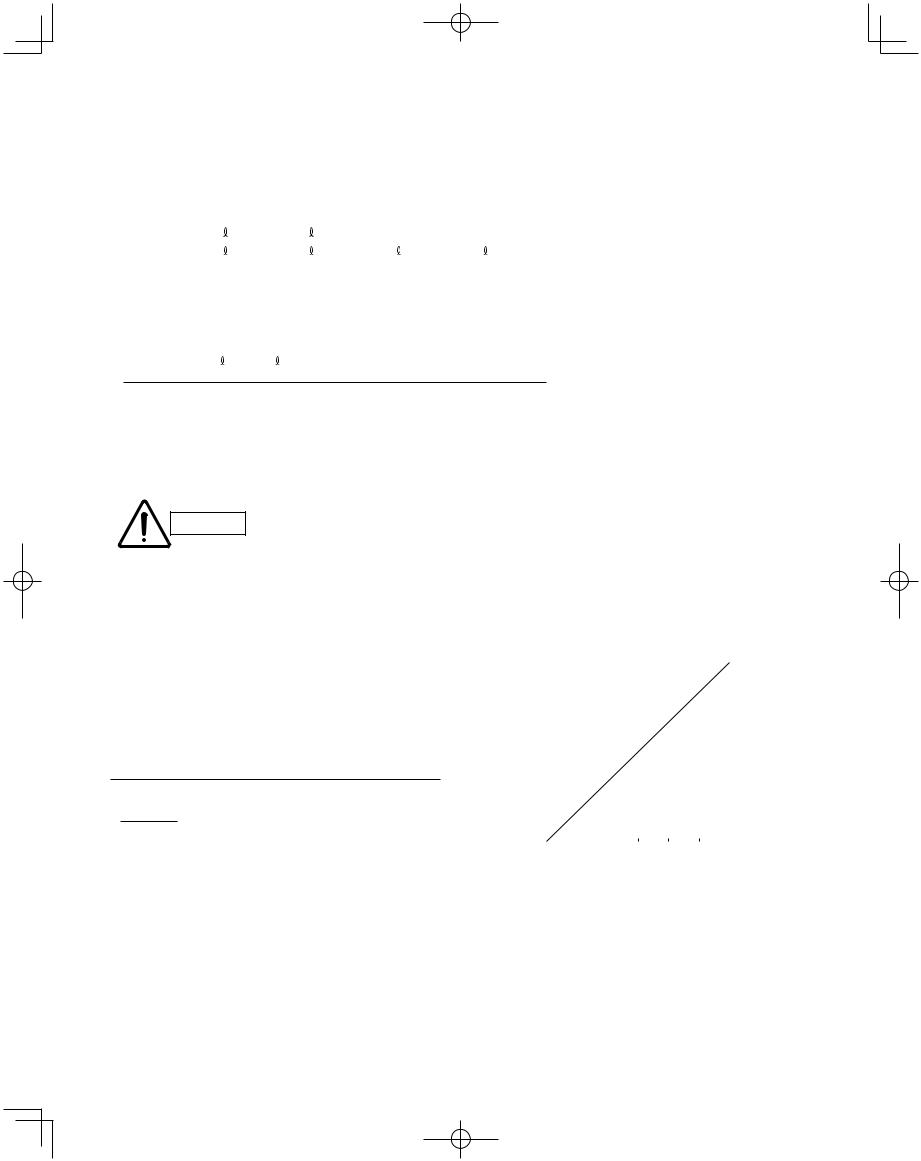
●Obtain liquid tubing size from Tables 1-10, 11, 12 and 15.
Main tubing
LA = ø5/8 (ft.) (Total capacity of indoor unit is 179,400 BTU/h) LB = ø1/2 (ft.) (Total capacity of indoor unit is 131,600 BTU/h) LC = ø3/8 (ft.) (Total capacity of indoor unit is 83,800 BTU/h)
The longest tubing length in this example (LA = 131 ft.)
Distribution joint tubing |
|
|
|
|
Outdoor side |
A: ø3/8 (ft.) |
B: ø3/8 (ft.) |
(from outdoor unit connection tubing) |
|
Indoor side |
1: ø3/8 (ft.) |
2: ø3/8 (ft.) |
3: ø3/8 (ft.) |
4: ø3/8 (ft.) (from indoor unit connection tubing) |
●Obtain charge amount for each tubing size
Note that the charge amounts per 1 meter are different for each liquid tubing size.
ø5/8 (ft.) → LA |
: 131 ft. × 1.99 oz/ft. |
= |
261 oz |
ø1/2 (ft.) → LB |
: 16 ft. × 1.38 oz/ft. |
= |
22 oz |
ø3/8 (ft.) → LC + A – B + 1 – 4 |
: 225 ft. × 0.602 oz/ft. |
= |
135 oz |
Total 418 oz
Additional refrigerant charge amount is 418 oz.
Remark:
When operating only one model CHDZ (R) 14053 or jointing with one more model, be sure to include the values in Table 1-16-2 Necessary Amount of Refrigerant Charge Per Unit.
Be sure to check the limit density for
CAUTION
the room in which the indoor unit is
installed.
Checking of limit density
Density limit is determined on the basis of the size of a room using an indoor unit of minimum capacity. For instance, when an indoor unit is used in a room (floor area 161 ft.2 × ceiling height 8.8 ft. = room volume 1417 ft.3), the graph at right shows that the minimum room volume should be 2455 ft.3
(floor area 279 ft.2) for refrigerant of 418 oz.
<Determination by calculation>
Overall refrigerant charge amount for the air conditioner: oz
(Minimum room volume for indoor unit: ft.3)
418(oz)
== 0.29 (oz/ft.3) < 0.3 (oz/ft.3)
1417 (ft.3)
Therefore, openings such as louvers are not required for this
room.
Min. indoor volume
ft.3 |
|
|
|
|
|
|
|
|
|
|
|
ft.2 |
|
|
4000 |
|
|
|
|
|
|
|
|
|
|
|
|
454 |
|
|
|
|
|
|
|
|
|
|
|
|
|
|
||
|
|
|
|
|
|
|
|
|
|
|
|
|
|
|
3500 |
|
Range below |
|
|
|
|
|
|
|
398 |
|
|||
|
|
|
|
|
|
|
|
|
||||||
3000 |
|
the density limit of |
|
|
|
|
|
341 |
area |
|||||
|
0.3 oz/ft.3 |
|
|
|
|
|
|
|
||||||
|
|
|
|
|
|
|
|
|||||||
2500 |
|
(countermeasures |
|
|
|
|
|
284 |
||||||
|
|
|
|
|
|
floor |
||||||||
|
not needed) |
|
|
|
|
|
|
|
||||||
|
|
|
|
|
|
|
|
|||||||
|
|
|
|
|
|
|
|
|
|
|||||
|
|
|
|
|
|
|
|
|
|
|
||||
2000 |
|
|
|
|
|
|
|
|
|
|
|
|
227 |
indoor |
|
|
|
|
|
|
|
|
|
|
|
|
|||
1500 |
|
|
|
|
|
|
|
|
|
|
|
|
170 |
|
|
|
|
|
|
Range above |
|
||||||||
|
|
|
|
|
|
|
|
Min. |
||||||
1000 |
|
|
|
|
|
the density limit of |
|
114 |
||||||
|
|
|
|
|
|
|||||||||
500 |
|
|
|
|
|
0.3 oz/ft.3 |
|
|
|
57 |
|
|||
|
|
|
|
|
(countermeasures |
|
|
|||||||
|
|
|
|
|
|
|
||||||||
0 |
|
|
|
|
|
needed) |
|
|
|
0 |
|
|||
|
|
|
|
|
|
|
|
|
|
|
|
|
||
|
|
|
|
|
|
|
|
|
|
|
|
|
||
0 |
200 |
400 |
600 |
800 |
1000 |
1200 |
|
|||||||
|
|
|
|
|
|
|
|
|
|
|
|
|
oz |
|
Total amount of refrigerant
(when the ceiling is 8.8 ft. high)
22
W-3WAY_ECO-i_US.indd 22 |
2008/02/07 10:55:42 |
|
|
|
|
|
|
||
|
|
|
||
|
|
|
|
|
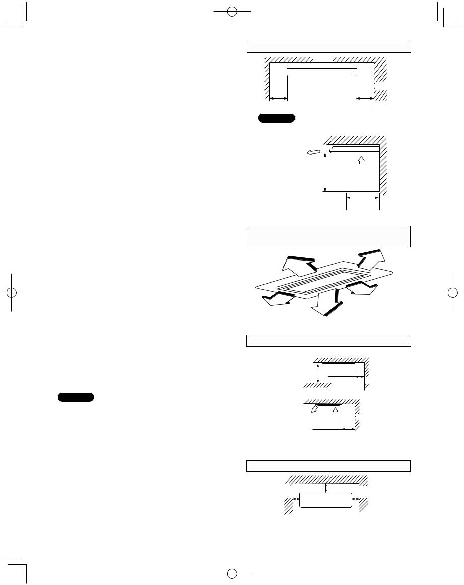
2. SELECTING THE INSTALLATION SITE
2-1. Indoor Unit
AVOID:
●areas where leakage of flammable gas may be expected.
●places where large amounts of oil mist exist.
●direct sunlight.
●locations near heat sources which may affect the performance of the unit.
●locations where external air may enter the room directly. This may cause “sweating” on the air discharge ports, causing them to spray or drip.
●locations where the remote controller will be splashed with water or affected by dampness or humidity.
●installing the remote controller behind curtains or furniture.
●locations where high-frequency emissions are generated.
DO:
●select an appropriate position from which every corner of the room can be uniformly cooled.
●select a location where the ceiling is strong enough to support the weight of the unit.
●select a location where tubing and drain pipe have the shortest run to the outdoor unit.
●allow room for operation and maintenance as well as unrestricted air flow around the unit.
●install the unit within the maximum elevation difference above or below the outdoor unit and within a total tubing length (L) from the outdoor unit as detailed in Table 1-9.
●allow room for mounting the remote controller about 3 ft. off the floor, in an area that is not in direct sunlight nor in the flow of cool air from the indoor unit.
NOTE
Air delivery will be degraded if the distance from the floor to the ceiling is greater than 10 ft.
23
Ceiling-MountedType
Ceiling |
Wall |
Min. 10 in. |
Min. 10 in. |
Front view
NOTE
The rear of the indoor unit can be installed flush against the wall.
Air discharge
Min. 2 ft. |
|
|
|
Air intake |
|
|
|
||
|
|
|
|
|
|
|
|
|
|
Side view |
Max. 10 in. |
|
Obstacle |
Fig. 2-1
Concealed Duct (High-Static Pressure)Type
4-Way Air Discharge Semi-Concealed Type
3 ft.
3 ft.
3 ft.
3 ft. |
3 ft. |
|
Fig. 2-2
1-Way Air Discharge Semi-Concealed Type
Ceiling
Min. 3 ft.
Min. 2 in.
Wall
Obstacle
Air
discharge Air
intake Wall
Min. 2 in.
Side view
Fig. 2-3
Wall-MountedType
Min. |
Min.6 in. |
Min. |
6 in. |
|
6 in. |
Front View
Fig. 2-4
W-3WAY_ECO-i_US.indd 23 |
2008/02/07 10:55:42 |
|
|
|
|
|
|
||
|
|
|
||
|
|
|
|
|
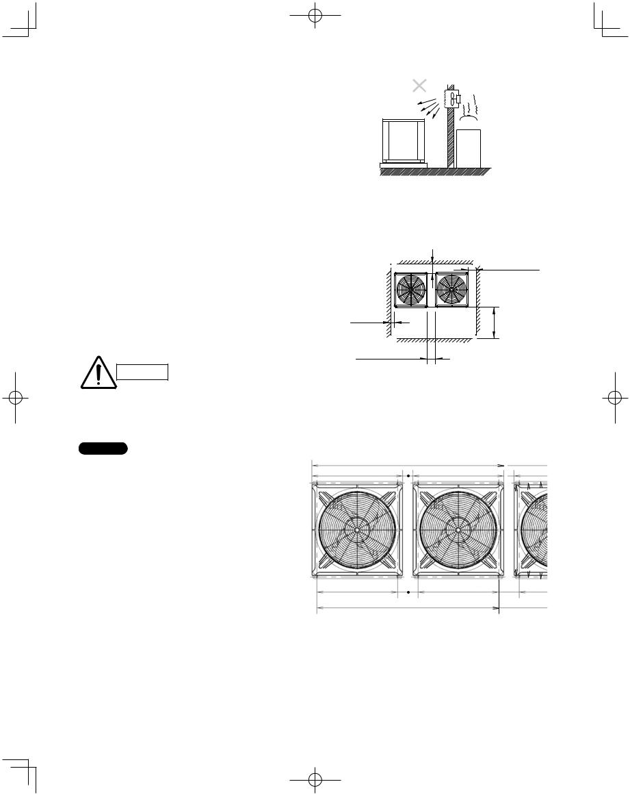
2-2. Outdoor Unit
AVOID:
●heat sources, exhaust fans, etc.
●damp, humid or uneven locations
●indoors (no-ventilation location)
DO:
●choose a place as cool as possible.
●choose a place that is well ventilated.
●allow enough room around the unit for air intake/ exhaust and possible maintenance.
Installation Space
Install the outdoor unit where there is enough space for ventilation. Otherwise the unit may not operate properly. Fig. 2-6 shows the minimum space requirement around the outdoor units when 3 sides are open and only 1 side is shuttered, with open space above the unit. The mounting base should be concrete or a similar material that allows for adequate drainage. Make provisions for anchor bolts, platform height, and other site-specific installation requirements.
● Leave space open above the
CAUTION unit.
● Construct louvers or other openings in the wall, if necessary, to ensure adequate ventilation.
NOTE
●Do not do any wiring or tubing within 1 ft. of the front panel, because this space is needed as a servicing space for the compressor.
●Ensure a base height of 4 in. or more to ensure that drainage water does not accumulate and freeze around the bottom of the unit.
●If installing a drain pan, install the drain pan prior to installing the outdoor unit.
*Make sure there is at least 6 in. between the outdoor unit and the ground.
Also, the direction of the tubing and electrical wiring should be from the front of the outdoor unit.
Exhaust fan
Hot air
 Heat Out-
  source door
unit
Fig. 2-5
Example of installation of 2 units (When wall height is below 6 ft.)
* More than 4 in.
* More than 4 in.
More than |
|
2 in. |
More than |
|
1.7 ft. |
* More than 4 in.
*However, be sure to ensure a space of 1 ft. or more at either the right side or the rear of the unit.
Fig. 2-6
74-1/64 (Ceiling panel dimensions) |
3-15/16 |
|
|
|
|
|
|
|
|
|
||||
|
|
|
|
|
|
|
|
|
|
|
|
|
|
|
35-3/64 (Ceiling panel dimensions) |
35-3/64 (Ceiling panel dimensions) |
|
|
|
|
|
|
|
||||||
|
|
|
|
|
|
|
|
|
|
|
|
|
|
|
|
|
|
|
|
|
|
|
35-3/64 (Ceiling panel dimensions) |
|
36-7/32 (Installation hole pitch) |
37-13/32 (Maximum dimensions) |
|
||
|
|
|
|
|
|
|
|
|
|
|
|
|||
|
|
|
|
|
|
|
|
|
|
|
|
|
|
|
31-7/64 (Installation hole pitch) |
|
31-7/64 (Installation hole pitch) |
|
|
|
|
|
|
|
|||||
|
|
|
|
7-7/8 |
|
|
|
|
|
|
|
|
|
|
|
|
|
|
|
|
|
|
|
|
|
|
|
|
|
|
|
|
|
|
|
|
|
|
|
|
|
|
||
|
|
|
|
|
|
|
|
|
|
|
|
|
|
|
70-5/64 (Installation hole pitch) |
|
|
|
|
|
|
|
|
|
|||||
|
|
|
|
|
|
|
|
|
|
|
||||
Top view |
|
|
|
|
|
Unit: in. |
|
|||||||
|
|
|
|
|
||||||||||
|
|
|
|
|
|
|
|
|
|
|
|
|
|
|
Fig. 2-7
24
W-3WAY_ECO-i_US.indd 24 |
2008/02/07 10:55:43 |
|
|
|
|
|
|
||
|
|
|
||
|
|
|
|
|
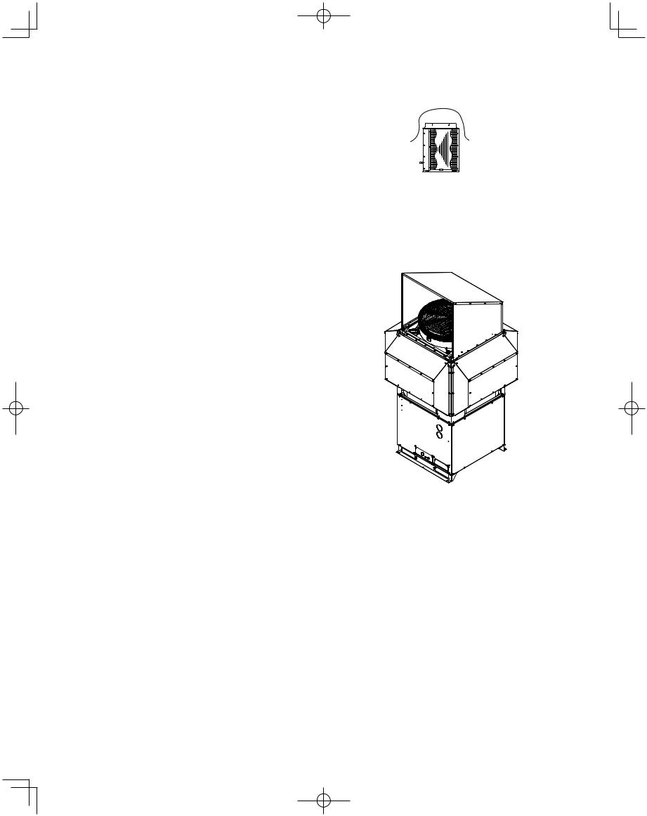
2-3. Precautions When Installing in Heavy Snow
Areas
a)The platform should be higher than the maximum snow depth. (Fig. 2-8)
b)The 2 anchoring feet of the outdoor unit should be used for the platform, and the platform should be installed beneath the air-intake side of the outdoor unit.
c)The platform foundation must be solid and the unit must be secured with anchor bolts.
d)When installing on a roof subject to strong wind, countermeasures must be taken to prevent the unit from being overturned.
25
AVOID
Without snowproof ducting
(Without platform)
Fig. 2-8
Fig. 2-9
W-3WAY_ECO-i_US.indd 25 |
2008/02/07 10:55:43 |
|
|
|
|
|
|
||
|
|
|
||
|
|
|
|
|
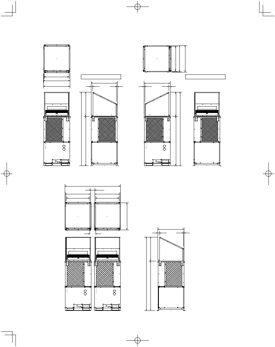
2-4. Dimensions of Wind Ducting
Reference diagram for air-discharge chamber (field supply)
Ceiling panel
33-3/16 35-3/64 (Ceiling panel dimensions) 35-15/64 (Maximum bracket dimensions)
unit: in.
Ceiling panel
33-3/16 |
Air direction: Front direction |
|
|
Air direction: Right direction |
||
35-3/64 |
|
|
||||
|
35-3/64 |
|
|
35-3/64 |
|
|
(Ceiling panel dimensions) |
|
|
|
|
||
35-15/64 |
2-11/64 |
(Ceiling panel dimensions) |
15/16 |
15/16 |
(Ceiling panel dimensions) |
2-11/64 |
(Maximum bracket dimensions) |
|
|
|
|
|
|
|
(32-5/64) |
|
|
|
|
(32-5/64) |
97-29/32 |
97-29/32 |
65-53/64 |
65-53/64 |
Front view |
Right side view |
Front view |
Right side view |
|
Note: Can be installed so that the air direction is to the front, right, left or rear direction. |
|
|
2-unit installation
74-7/32 (2-unit installation: maximum dimensions) |
|
|
|
5-25/32 |
|
33-3/16 |
33-3/16 |
|
31-7/64 |
31-7/64 |
Top view |
|
(Installation hole pitch) |
|
36-7/32 (Installation hole pitch)
7-7/8
unit: in.
|
35-3/64 |
|
2-11/64 |
(Ceiling panel dimensions) |
15/16 |
|
||
(32-5/64) |
|
|
97-29/32
65-53/64
Front view |
Right side view |
26
W-3WAY_ECO-i_US.indd 26 |
2008/02/07 10:55:45 |
|
|
|
|
|
|
||
|
|
|
||
|
|
|
|
|
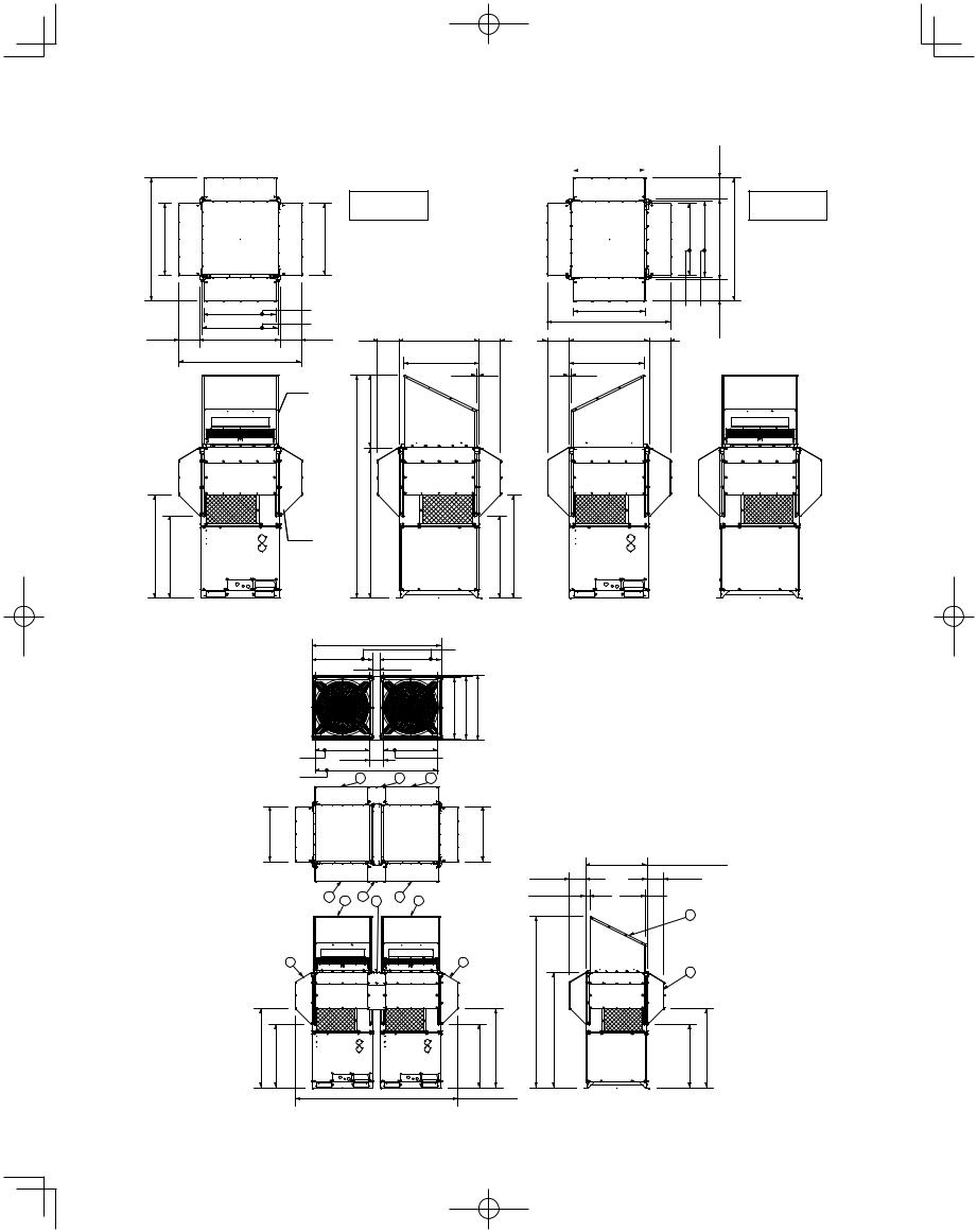
2-5. Dimensions of Snow Ducting
Reference diagram for snow-proof ducting (field supply)
|
|
|
Air direction: |
|
|
|
Front direction |
-55/64 |
-17/32 |
-17/32 |
Ceiling panel |
53 |
31 |
31 |
|
|
|
31-17/32 (Air intake duct) |
|
|
|
|
|
33-3/16 (Air outlet duct) |
|
|
|
9-13/32 |
35-3/64 |
9-13/32 |
9-13/32 |
35-3/64 |
9-13/32 |
|
(Ceiling panel dimensions) |
|
(Ceiling panel dimensions) |
||
|
53-55/64 |
|
|
32-7/8 |
15/16 |
|
|
|
|
|
|
1 pc.
(32-5/64)
|
31-17/32 |
|
-13/32 |
|
|
||
|
|
|
9 |
35-3/64 |
53-55/64 |
|
31-17/32 |
|
duct) |
duct) |
13/32- |
|
53-55/64 |
|
|||
|
|
|
|
|
|
9-13/32 |
35-3/64 |
9-13/32 |
intake |
outlet |
9 |
|
|
|
|
|
|
(Ceiling panel dimensions) |
|
|
|
||
15/16 |
32-7/8 |
|
(Air |
(Air |
|
|
|
|
|||
|
|
|
31-17/32 |
33-3/16 |
|
Air direction: Right direction
Ceiling panel
unit: in.
45-5/16 |
-7/64 |
|
36 |
97-29/32 |
53/64 |
7/64- |
5/16-45 |
|
4 pc. |
65- |
|
||
|
|
|
|
|
|
|
36 |
|
|
Front view |
|
Right side view |
Front view |
Right side view |
Note: Can be installed so that the air direction is to the front, right, left or rear direction.
74-1/64 (Ceiling panel dimensions)
2-unit installation |
35-3/64 |
35-3/64 |
|
|
3-15/16 |
35-3/64
Ceiling panel dimensions
-367/32 13/32-37 |
Top (Before installation of snowfall protection duct) |
|
|
31-7/64 |
31-7/64 |
|
Installation hole pitch |
7-7/8 |
|
Installation hole pitch |
|
|
70-5/64 |
|
Installation hole pitch |
2 |
3 |
2 |
unit: in.
|
31-17/32 |
|
|
|
|
31-17/32 |
|
|
|
35-3/64 (Ceiling panel dimensions) |
|
|
|
|
|
|
|
|
|
|
|
||
|
|
|
|
|
|
Ceiling panel |
9-29/64 |
9-29/64 |
|||
|
2 |
1 |
3 |
3 |
2 |
1 |
|
2-11/64 |
7/8 |
|
|
|
|
|
|
|
|
||||||
|
|
|
|
|
|
|
|
|
|||
|
|
|
|
|
|
|
|
|
|
1 |
|
|
2 |
|
|
|
|
2 |
|
|
|
2 |
|
|
|
|
|
|
|
|
|
|
|
|
|
45-5/16 |
36-7/64 |
|
|
|
|
36-7/64 |
45-5/16 |
97-29/32 |
65-53/64 |
36-7/64 |
45-5/16 |
|
|
|
92-53/64 |
|
|
|
|
|
|
|
|
|
|
|
Front view |
|
|
|
|
Right side view |
|
||
27
W-3WAY_ECO-i_US.indd 27 |
2008/02/07 10:55:46 |
|
|
|
|
|
|
||
|
|
|
||
|
|
|
|
|
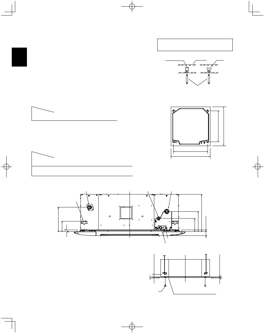
3.HOW TO INSTALL THE INDOOR UNIT
■4-Way Air Discharge Semi-Concealed Type (X Type) 3-1. Preparation for Suspending
This unit uses a drain pump. Use a carpenter’s level to check that the
Xunit is level.
3-2. Suspending the Indoor Unit
(1)Fix the suspension bolts securely in the ceiling using the method shown in the diagrams (Figs. 3-1 and 3-2), by attaching them to the ceiling support structure, or by any other method that ensures that the unit will be securely and safely suspended.
(2)Follow Fig. 3-2 and Table 3-1 to make the holes in the ceiling.
Table 3-1 |
Unit: in. (mm) |
Note: For DC Fan Tap Change Procedure for 4-Way Cassette, see page 34.
Hole-in-anchor |
|
|
Hole-in-plug |
Concrete |
Insert |
Suspension bolt (M10 or 3/8") (field supply)
Fig. 3-1
Length |
A |
B |
C |
D |
|
Type |
|||||
12, 18, 24, 36 |
31-1/32 |
28-15/32 |
34-27/32 |
34-27/32 |
|
(788) |
(723) |
(885) |
(885) |
||
|
|||||
|
|
|
|
|
(3)Determine the pitch of the suspension bolts using the supplied full-scale installation diagram. The diagram and table (Fig. 3-3 and Table 3-2) show the relationship between the positions of the suspension fitting, unit, and panel.
Table 3-2 |
|
|
|
|
|
Unit: in. (mm) |
||
|
|
|
|
|
|
|
|
|
Length |
A |
B |
C |
|
D |
|
E |
|
Type |
|
|
|
|||||
12, 18, 24 |
4-29/64 |
6-13/16 |
10-5/64 |
|
8-17/64 |
|
3-15/32 |
|
(113) |
(173) |
(256) |
|
(210) |
|
(88) |
|
|
|
|
|
|
|||||
36 |
4-29/64 |
6-13/16 |
12-9/16 |
|
8-17/64 |
|
3-15/32 |
|
(113) |
(173) |
(319) |
|
(210) |
|
(88) |
|
|
|
|
|
|
|||||
|
|
Drain outlet(other side) |
|
Refregerant tubing joint(liquid side) |
||||
|
|
(VP25) |
|
|||||
B (suspension bolt pitch) |
(ceiling opening dimension) |
|
D |
A (suspension bolt pitch)
C (ceiling opening dimension)
Fig. 3-2
Refregerant tubing joint(gas side)
Suspension lug |
|
|
|
|
C |
D E |
A B |
1-3/8 (35) |
Fig. 3-3 |
Power supply outlet |
|
Inter-unit control wiring |
Unit: in. (mm) |
3-3. Placing the Unit Inside the Ceiling
(1)When placing the unit inside the ceiling, determine the pitch of the suspension bolts using the supplied full-scale installation diagram. (Fig. 3-4)
Tubing and wiring must be laid inside the ceiling when suspending the unit. If the ceiling is already constructed, lay the tubing and wiring into position for connection to the unit before placing the unit inside the ceiling.
Over 19/32 (15) |
Supplied bolt
– 43/64 |
17) |
15/32 |
(12 – |
Full-scale installation diagram |
Unit: in. (mm) |
(printed on top of container box) |
|
Fig. 3-4
28
W-3WAY_ECO-i_US.indd 28 |
2008/02/07 10:55:47 |
|
|
|
|
|
|
||
|
|
|
||
|
|
|
|
|
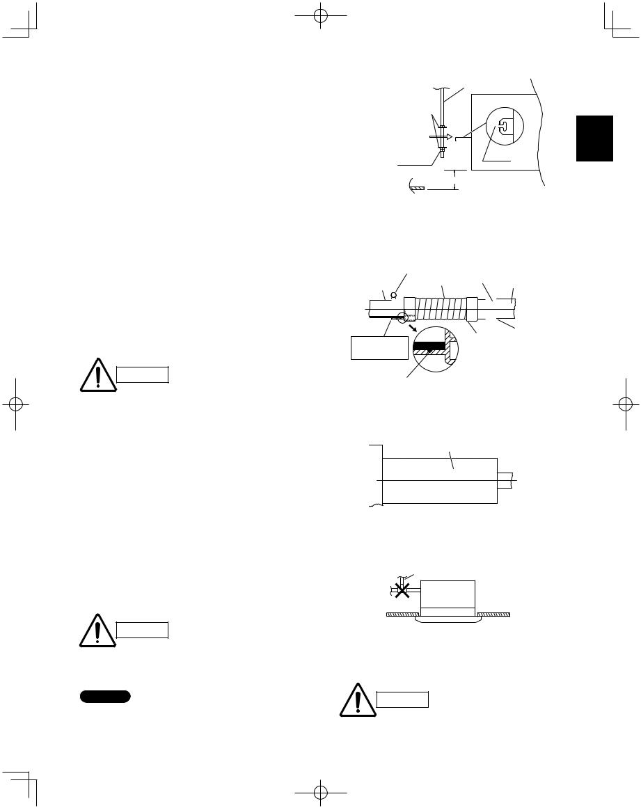
(2)The length of suspension bolts must be appropriate for a distance between the bottom of the bolt and the bottom of the unit of more than 19/32 in. as shown in Fig. 3-5.
(3)Thread the 3 hexagonal nuts and 2 washers (field supply) onto each of the 4 suspension bolts as shown in Fig. 3-5. Use 1 nut and 1 washer for the upper side, and 2 nuts and 1 washer for the lower side, so that the unit will not fall off the suspension lugs.
(4)Adjust so that the distance between the unit and the ceiling bottom is 15/32 to 43/64 in. Tighten the nuts on the upper side and lower side of the suspension lug.
(5)Remove the protective polyethylene used to protect the fan parts during transport.
3-4. Installing the Drain Piping
(1)Prepare a standard hard PVC pipe (O.D. 1-1/4 in.) for the drain and use the supplied drain hose and hose band to prevent water leaks.
The PVC pipe must be purchased separately. The unit’s transparent drain port allows you to check drainage. (Fig. 3-6)
CAUTION
●Insert the drain pipe until it contacts the socket, as shown in Fig. 3-6, then secure it tightly with the hose band.
●Do not use adhesive when connecting the supplied hose.
Reasons: 1. It may cause water to leak from the connection. Since the connection is slippery just after the adhesive has been applied, the pipe easily slips off.
2.The pipe cannot be removed when maintenance is needed.
●Do not bend the supplied drain hose 90° or more. The hose may slip off.
●Align the hose bands with the end of the hose. Tighten the hose band firmly. Please make sure that the bead is not covered by the hose band. (Fig. 3-6)
Tighten the hose clamps so
CAUTION
their locking nuts face upward. (Fig. 3-6)
(2)After checking the drainage, wrap the supplied packing and drain pipe insulator around the pipe. (Fig. 3-7)
NOTE
Make sure the drain pipe has a downward gradient (1/100 or more) and that there are no water traps.
29
|
Suspension bolt |
Nuts and washers |
Suspension lug |
(use for upper and lower) |
|
X
Double nut |
Notch |
|
15/32 – 43/64 (12 – 17)
Unit: in. (mm)
Fig. 3-5
|
|
|
|
|
|
|
Hard PVC |
|
|||
|
Hose band |
|
socket |
Hard PVC pipe |
|||||||
|
|
VP-25 |
|||||||||
|
Supplied |
VP-25 |
|||||||||
Connection pipe |
|||||||||||
drain hose |
(Field supply) |
(Field supply) |
|||||||||
(drain port) |
|||||||||||
|
|
|
|
|
|||||||
|
|
|
|
|
|
|
|
|
|
|
|
|
|
|
|
|
|
|
|
|
|
|
|
|
|
|
|
|
|
|
|
|
|
|
|
|
|
|
|
|
|
|
|
|
|
|
|
|
|
|
|
|
|
|
|
|
|
|
|
|
|
|
|
|
|
|
|
|
|
|
|
|
PVC adhesive |
|
Align the hose |
Packing |
|
(supplied) |
||
band with the end |
||
|
||
of the pipe |
|
Bead
Fig. 3-6
Drain insulator (supplied)
Fig. 3-7
Air bleeder prohibited
Fig. 3-8
CAUTION
● Do not install an air bleeder as this may cause water to spray from the drain pipe outlet. (Fig. 3-8)
W-3WAY_ECO-i_US.indd 29 |
2008/02/07 10:55:47 |
|
|
|
|
|
|
||
|
|
|
||
|
|
|
|
|
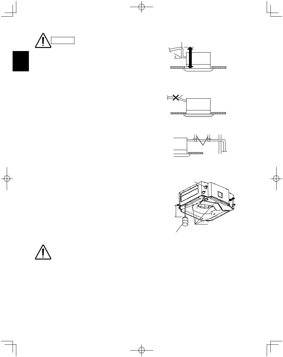
CAUTION
●In cases where it is necessary to raise the height of the drain piping, the drain piping can be raised
Xto a maximum height of 33-15/32" above the bottom surface of the ceiling. Under no conditions attempt to raise it higher than 33-15/32" above the bottom surface of the ceiling. Doing so will result in water leakage. (Fig. 3-9)
●Do not install the pipe with an upward gradient from the connection port. This will cause the drain water to flow backward and leak when the unit is not operating. (Fig. 3-10)
●Do not apply force to the piping on the unit side when connecting the drain pipe. The pipe should not be allowed to hang unsupported from its connection to the unit. Fasten the pipe to a wall, frame, or other support as close to the unit as possible. (Fig. 3-11)
●Provide insulation for any pipes that are run indoors.
3-5. Checking the Drainage
After wiring and drain piping are completed, use the following procedure to check that the water will drain smoothly. For this, prepare a bucket and wiping cloth to catch and wipe up spilled water.
(1)Connect power to the power terminal board (R, S terminals) inside the electrical component box.
(2)Slowly pour approx. 0.3 gal of water into the drain pan to check drainage. (Fig. 3-12)
(3)Short the check pin (CHK) on the indoor control board and operate the drain pump. Check the water flow through the transparent drain pipe and see if there is any leakage.
(4)When the check of drainage is complete, open the check pin (CHK) and remount the tube cover.
CAUTION |
Be careful since the fan will |
|
start when you short the pin |
||
|
||
|
||
|
on the indoor control board. |
30
W-3WAY_ECO-i_US.indd 30
 11-3/16 in. or less (as short as possible)
33-15/32 in. or less
0– 45°
*Length of supplied drain hose = 9-27/32 in.
Fig. 3-9
Upward gradient prohibited
Fig. 3-10
Support pieces
Fig. 3-11
Drainage check
Over 3-15/16 in.
Drain pan outlet Water (Approx. 0.3 gal)
Plastic container for water intake
Fig. 3-12
2008/02/07 10:55:47
 Loading...