


INSTRUCTION MANUAL
Color TFT LCD monitor
VMC-L1015 VMC-L1017 VMC-L1019
About this manual
•Before installing and using this unit, please read this manual carefully. Be sure to keep it handy for later reference.
•This manual gives basic connections and operating instructions for 3 models (VMC-L1015, L1017 and L1019).
Information to User
WARNING:
TO REDUCE THE RISK OF FIRE OR ELECTRIC SHOCK, DO NOT EXPOSE THIS PRODUCT TO RAIN OR MOISTURE.
DO NOT INSERT ANY METALLIC OBJECT THROUGH THE VENTILATION GRILLS.
CAUTION
RISK OF ELECTRIC SHOCK
DO NOT OPEN
CAUTION: TO REDUCE THE RISK OF ELECTRIC SHOCK.
DO NOT REMOVE COVER (OR BACK). NO USER-SERVICEABLE PARTS INSIDE.
REFER SERVICING TO QUALIFIED SERVICE PERSONNEL.
Explanation of graphical Symbols
The lightning flash with arrowhead symbol, within an equilateral triangle, is intended to alert the user to the presence of uninsulated “dangerous voltage” within the product's enclosure that may be of sufficient magnitude to constitute a risk of electric shock to persons.
The exclamation point within an equilateral triangle is intended to alert the user to the presence of important operating and maintenance (servicing) instructions in the literature accompanying the product.
FCC COMPLIANCE STATEMENT
FCC INFORMATION: THIS EQUIPMENT HAS BEEN TESTED AND FOUND TO COMPLY WITH THE LIMITS FOR A CLASS B DIGITAL DEVICE, PURSUANT TO PART 15 OF THE FCC RULES. THESE LIMITS ARE DESIGNED TO PROVIDE REASONABLE PROTECTION AGAINST HARMFUL INTERFERENCE WHEN THE EQUIPMENT IS OPERATED IN A COMMERCIAL ENVIRONMENT. THIS EQUIPMENT GENERATES, USES, AND CAN RADIATE RADIO FREQUENCY ENERGY AND IF NOT INSTALLED AND USED IN ACCORDANCE WITH THE INSTRUCTION MANUAL, MAY CAUSE HARMFUL INTERFERENCE TO RADIO COMMUNICATIONS. OPERATION OF THIS EQUIPMENT IN A RESIDENTIAL AREA IS LIKELY TO CAUSE HARMFUL INTERFERENCE IN WHICH CASE THE USER WILL BE REQUIRED TO CORRECT THE INTERFERENCE AT HIS OWN EXPENSE.
CAUTION: CHANGES OR MODIFICATIONS NOT EXPRESSLY APPROVED BY THE PARTY RESPONSIBLE FOR COMPLIANCE COULD VOID THE USER'S AUTHORITY TO OPERATE THE EQUIPMENT.
THIS CLASS B DIGITAL APPARATUS MEETS ALL REQUIREMENTS OF THE CANADIAN INTERFERENCE-CAUSING EQUIPMENT REGULATIONS.
CET APPAREIL NUMÉRIQUE DE LA CLASSE A RESPECTE TOUTES LES EXIGENCES DU RÈGLEMENT CANADIEN SUR LE MATÉRIEL CAUSANT DES INTERFÉRENCES.
– 1 –
Precautions
•Use only the power source specified on the unit.
•When not using this unit for a long period of time, or when cleaning it, be sure to disconnect the power plug from the AC outlet.
•Do not allow anything to rest on the power cord. And do not place this unit where people will tread on the cord. Do not overload wall outlets or power cords as this can result in a fire or electric shock.
•Avoid using this unit under the following conditions:
-in extremely hot, cold or humid places,
-in dusty places,
-near appliances generating strong magnetic fields,
-in places subject to direct sunlight,
-in badly ventilated places,
-in automobiles with doors closed.
•Do not cover the ventilation slots while in operation as this could obstruct the required ventilation flow.
•When dust accumulates on the screen surface, clean it with a soft cloth.
•Unplug this unit from the AC outlet and refer servicing to qualified service personnel under the following conditions:
-when the power cord is frayed or the plug is damaged,
-if liquid has been spilled into the unit,
-if the unit has been dropped or the cabinet has been damaged,
-when the unit exhibits a distinct change in performance.
•Do not attempt to service this unit yourself as opening or removing covers may expose you to dangerous voltage or other hazards. Always refer servicing to qualified service personnel.
Contents
Names of controls/parts . . . . . . . . . . . . . . . . . . . . . . . . . . . 3 Connection instructions . . . . . . . . . . . . . . . . . . . . . . . . . . . . 4
Instructions for use . . . . . . . . . . . . . . . . . . . . . . . . . . . . . . . 5
Monitoring display adjustment. . . . . . . . . . . . . . . . . . . . . . . 6
Computer display adjustment . . . . . . . . . . . . . . . . . . . . . . . 7
Troubleshooting. . . . . . . . . . . . . . . . . . . . . . . . . . . . . . . . . . 8
External dimensions & adjustable angle . . . . . . . . . . . . . . . 9
Specifications . . . . . . . . . . . . . . . . . . . . . . . . . . . . . . . . . . 10
Features
• Multilingual menu support
English/Chinese/French/German/Spanish/Italian/
Japanese
•Picture in Picture (PIP) function
•NTSC/PAL automatic select
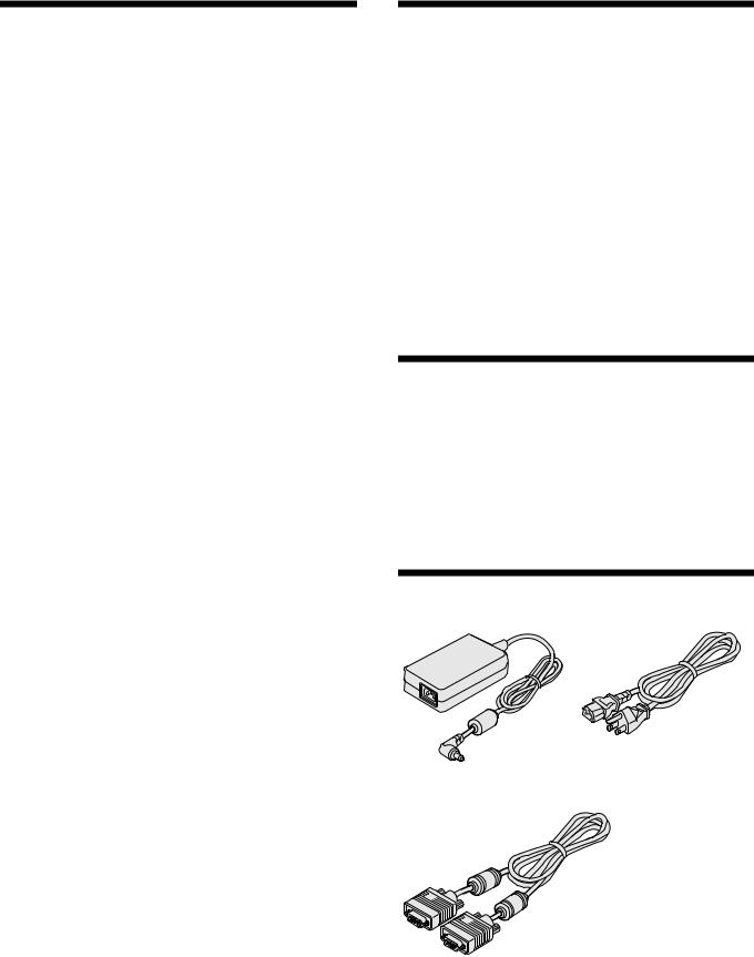
Accessories
■ AC adapter |
■ AC cord |
■ VGA connecting cable
– 2 –

Names of controls/parts
Front view
Viewing area |
|
Adjustment control (MENU) |
Automatic display adjustment control |
(AUTO) |
|
For fine adjustment. (Pages 6, 7) |
Automatically adjusts the screen |
|
(for use with VGA connections). (Page 5) |
 Contrast adjustment control
For adjusting the screen contrast. (Page 5)
• Select the appropriate menu item.
MENU |
AUTO |
Power button (POWER)
Turns the power on or off.
MODE POWER 
|
|
|
|
|
|
|
Volume adjustment control |
Power indicator |
|||
|
Adjusts the volume level. (Page 5) |
light |
|||
|
• For adjustment, change the setting value. |
|
|
||
|
|
|
|
|
|
Brightness adjustment control |
Input mode control (MODE) |
||||
Adjusts the brightness of the screen. (Page 5)
• Select the appropriate menu item.
Changes the input mode. (Page 5)
Rear view
DC IN
VGA IN
BNC IN
BNC OUT
Y/C IN
Y/C OUT
AUDIO OUT AUDIO IN |
Audio-Out terminal (AUDIO OUT)
For audio output.
Audio-In terminal (AUDIO IN)
For audio input.


 Power input terminal (DC IN) (Page 4)

 VGA signal input terminal (VGA IN)
For the input of a computer
VGA (Video Graphics Array) signal.
Composite signal input terminal (BNC IN)
For the input of CCD camera surveillance image signal.
Composite signal output terminal (BNC OUT)
Sends the image to BNC IN.
 S-Video signal input terminal (Y/C IN)
For the input of S-Video signal.
 S-Video signal output terminal (Y/C OUT)
For the output of S-Video signal.
Pin number |
Signal |
4 |
IN |
3 |
|
1 |
GND (Y) |
2 |
|
1 |
|
2 |
GND (C) |
4 |
OUT |
3 |
|
3 |
Y |
||||
|
|
|
|||
4 |
C |
2 |
|
1 |
– 3 –
 Loading...