


VDC-HD3300/HD300P
VDC-HD3100/HD3100P
Features of This Camera
Specifications
Name and Function of Each Component
Connections
Lens Installation
Lens Adjustment
Viewing Firmware Version
Introduction1/15
The camera supports network operation. By simply connecting a LAN cable to it, you can construct the most advanced network monitoring system. From the Web browser (Internet Explorer) installed on your PC, you can operate the camera via the network in an easy-to-use manner.
In addition, it is a PoE product that can be powered through a LAN cable, so you can install it in locations where there is no power outlet nearby.
The camera has 4-megapixel CMOS sensor that produces clear images at ultra-high resolution.
The camera can deliver full HD H.264 video throughout the network. Connecting a high-definition monitor to your PC enables full high-definition video monitoring.
The camera supports both H.264 video and JPEG image compression formats, which you can choose from depending on the network environment.
The camera offers the focus assist function that supports focus adjustment at megapixel image resolution, allowing you to fine-tune the focus in optimal conditions in an easy manner.
The camera's motion sensor function can work in conjunction with any external alarm device, facilitating the construction of a high-level security system.
Installing associated software applications on your PC further extends the capabilities of your surveillance system.
Introduction 2/15
Image pickup device |
1/3" CMOS sensor |
Effective pixels |
16:9 1920 (H) × 1080 (V), 4:3 2288 (H) × 1712 (V) |
|
|
Lowest image |
50IRE: 1.0 lx (at F1.2, color mode, high gain) |
illumination |
50IRE: 0.06 lx (at F1.2, black-and-white mode, high gain) |
|
|
Video S/N ratio |
50dB (when AGC is “OFF”) |
|
|
Lens |
Built-in varifocal lens f=3 to 9mm, F1.2 to 2.1 |
|
|
Adjusting focus |
Focus assist function |
|
|
Day/Night function |
Auto, color, black-and-white, alarm input switching |
|
( (VDC-HD3300P/VDC-HD3300 only)) |
|
|
White balance |
Auto (ATW), one push (AWC), manual (R/B gain adjustable), indoor, outdoor, |
|
fluorescent |
|
|
Backlight compensation |
Multi-spot evaluative metering, center-weighted average metering, masking |
|
|
Electronic sensitivity |
Auto (32× max) or Off |
boosting |
|
|
|
Electronic shutter |
VDC-HD3300P/VDC-HD3100P: 1/25, 1/50, 1/120, 1/250, 1/500, 1/1000, 1/2000, |
|
1/4000, 1/10000D |
|
VDC-HD3300/VDC-3100: 1/30, 1/60, 1/100, 1/250, 1/500, 1/1000, 1/2000, 1/4000, |
|
1/10000 |
|
Long exposure shutter (1×, 2×, 4×, 8×, 16×, 32×) |
|
|
Iris control |
DC iris lens supported |
|
|
Camera settings |
Selectable between 2 camera setting patterns |
|
|
AGC gain |
Normal/Middle/High (Manual gain setting possible at Off) |
|
|
Gamma correction |
0.45, 1, Mode 1, Mode 2 |
|
|
Aperture compensation |
On/Off (Correction level adjustable) |
|
|
VIVID COLOR EFFECT |
ON/OFF |
|
|
DNR |
ON/OFF |
|
|
Mirror |
H/V/HV/OFF |
|
|
Privacy mask |
On/Off, max. 8 mask patterns |
|
|
Motion sensor |
On (masking/detection area setting)/Off |
|
|
Language selection |
English, French, German, Spanish, Japanese |
|
|
|
|
Video output |
Composite output |
|
|
LAN |
10BASE-T/100BASE-TX (RJ-45 connector) |
|
|
Alarm input |
2 (NO/NC), also serve as Day/Night switch (VDC-HD3300P/VDC-HD3300 only) |
|
|
Alarm output |
2 (NO/NC, 16V, 150 mA, open collector) |
|
|
Introduction 3/15
Image/video |
H.264/JPEG |
compression |
|
|
|
Video size (H.264) |
(16:9) 1920×1080, 1280×720, 640×360, 320×180 |
|
(4:3) 1600×1200, 1280×960, 1024×768, 640×480, 320×240 |
|
|
Video size (JPEG) |
(16:9)1920×1080, 1280×720, 1024×576, 640×360 |
|
(4:3) 2288×1712, 1600×1200, 1280×960, 1024×768, 800×600, 640×480, 320×240 |
|
|
Picture quality |
QUALITY mode: BASIC, NORMAL, ENHANCED, FINE, SUPER FINE |
|
BITRATE mode: User-specified bit rate |
|
|
Interface |
10BASE-T/100BASE-TX |
|
|
Protocol |
TCP/IP, UDP, HTTP, HTTPS, SMTP, NTP, DHCP, FTP, DDNS, RTP, RTSP, RTCP |
|
|
Simultaneous access |
20 |
|
|
Security |
BASIC authentication (ID/password), SSL, IP filtering |
|
|
|
|
International Waterproof |
IP66 |
and Dustproof Standard |
|
|
|
Operating ambient |
–10 to +50°C, 90% RH or less (no condensation) |
temperature/humidity |
|
|
|
Power source |
12 to 15 VDC/24 VAC±10%, 50/60 Hz, PoE |
|
|
Power consumption |
4,6W, 18W (with heater turned on) |
|
|
Weight |
770 g |
|
|
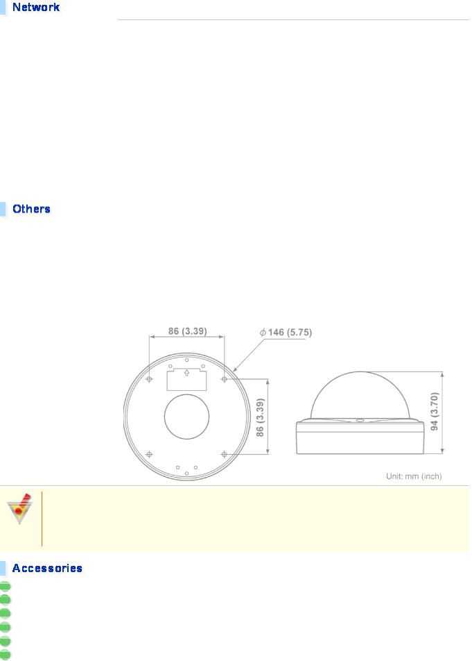
Dimensions |
|
Approvals: IP66/CE
This unit has been certified to IP66 standards when properly installed.
Use only an IP66 certified enclosure or an electrical box.
Ensure all openings in enclosure are sealed as per manufacturer's instructions.
1Video cable
2Cushioning sheet
3Hexagonal wrench
4Connector
5Pattern sheet
6CD-ROM
Introduction 4/15
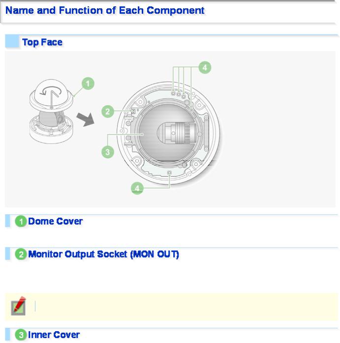
To remove the cover, remove the three screws using the supplied hex wrench.
Connecting the camera and monitor using the supplied cable enables you to perform focus and iris adjustments while monitoring the live video.
For details, see the “Connections” section.
You can use crocodile clip connectors instead of the supplied cable.
This cover protects the lens assembly.
Introduction 5/15
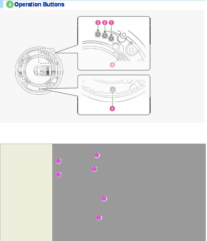
These buttons allow you to perform the following operations.
These operations may be performed with the Web browser installed on your PC. For details, refer to the linked information.
Operation
Restoring factory default settings
Resetting login password
Adjusting focus
Adjusting iris
Inverting video of wallmounted camera
Restarting camera
Viewing Firmware Version
Associated button and use |
Equivalent network operation screen |
|
|
Press the NEAR button ( 1 ) and the SET button |
OPTION SETTINGS (FACTORY |
( 3 ) simultaneously |
DEFAULT) |
|
|
Press the FAR button ( 2 ) and the SET button |
USER SETTINGS |
( 3 ) simultaneously |
|
|
|
For details, refer to the “Lens Adjustment” |
CAMERA SETTINGS (FOCUS |
section. |
ASSIST/IRIS SETTINGS) |
|
|
Press the REVERSE button ( 4 ) |
Not supported via network operation |
|
For details, see the “Installation |
|
Manual”. |
|
|
Press the RESET button ( 5 ) |
CAMERA SETTINGS (CAMERA |
|
REBOOT) |
|
|
For details, refer to the “Viewing Firmware |
OPTION SETTINGS (FIRMWARE |
Version” section. |
UPDATE) |
|
|
Introduction 6/15
 For the detailed procedures for connecting terminals and cables, refer to the “Connections” section.
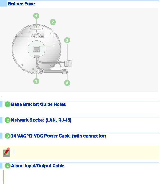
Use these coupling holes to mount the camera to the separately-sold base bracket.
Use this socket to connect the camera to your PC to enable network operation.
Use this cable to connect a 24 VAC or 12 VDC power supply.
There is no power indicator on the camera.
Alarm input cable: Connect an external switch, infrared sensor, or other device to detect alarm conditions such as the entry of an intruder.
Alarm output cable: Connect a buzzer, lamp, or other alarm device.
Introduction 7/15
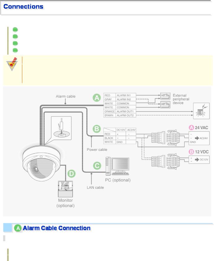
Perform the following connections according to the installation environment and application of your camera.
AAlarm Cable Connection
BPower Connection
CNetwork Connection
DCamera Monitor Connection
Before attempting the following connections, be sure to turn off all components of your system.
Improper connection may cause smoke or failures. Before attempting to connect each system component, carefully read the instruction manual that comes with it to familiarize yourself with the correct connection procedure.
Alarm Input Terminal Connection
Connect an alarm switch, infrared sensor, or other device to detect alarm conditions to the alarm input cable.
ALARM IN1: Red
ALARM IN2: gray
Introduction 8/15
After connecting an alarm device, configure the input conditions for the corresponding alarm input cable via network operation on the ALARM SETTINGS screen.
To use the alarm input cable as Day/Night switching signal path, follow the steps below. ( (This function is supported only by VDC-HD3300P/VDC-HD3300.))
Under [DAY/NIGHT], set [DAY/NIGHT] to “COLOR” and select the cable you want to use in [EXT ALARM].
On the ALARM SETTINGS screen, in [POLARITY], select the signal polarity of the alarm input terminal.
Connecting an external switch to ALARM IN1 allows you to set the system clock by operating the switch. To set the system clock, configure the [CLOCK IN] setting on the CLOCK SETTINGS screen.
Alarm Output Terminal Connection
Connect a buzzer, lamp, or other alarm device to the alarm output cable.
ALARM OUT1: Orange
ALARM OUT2: Brown
After connecting an alarm device, configure the output conditions for the corresponding alarm output cable via network operation on the ALARM SETTINGS screen.
Configuration of alarm output terminal is also possible via remote operation. For that, set [ALARM OUT] to “REMOTE” on the ALARM SETTINGS (ALARM OUT) screen.
Connect the power terminals (24 VAC/12 VDC) of the camera to a power supply.
A Connection to 24 VAC power supply
Although the power terminals have no polarity, the earth grounding wire must be connected to the GND (earth grounding) terminal.
B Connection to 12 VDC power supply
Note the polarity (+/–) of the power terminals when connecting the camera to a 12 VDC power supply. Incorrect polarity may cause damage to the camera.
Be sure to use an 18AWG or thicker wire power cable.
A voltage drop may occur depending on the thickness of the power cable. If you must use a long power cable, determine the cable type by ensuring that the voltage at the 24-VAC/12-VDC terminals is within the operating range of the camera.
When using PoE to power the camera, do not use the camera's power terminals.
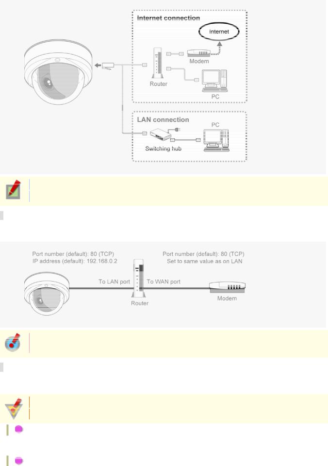
This camera is designed so that you can use all of its functions via network operation.
By connecting the network (LAN) socket of the camera to your PC using a LAN cable, you can configure and operate it from the Web browser installed on your PC.
Introduction 9/15
Use a LAN cable no longer than 100 m (109.4 yards) with the shield type CAT5 or higher.
The supported Web browser is Internet Explorer Ver.6.0 SP2 or higher, or Internet Explorer Ver.7.0.
About the internet connection
Port forwarding for the video port must be enabled on the broadband router.
For details on how to set port forwarding, please refer to your router's Instruction manual.
To connect two or more cameras, on the NETWORK SETTINGS screen, assign them with port numbers that are different from that of the first camera.
Using PoE
This camera supports PoE (Power over Ethernet). This means that you can install the camera in locations where there is no 24-VAC/12-VDC power outlet nearby.
When using PoE to power the camera, do not use the camera's power terminals.
Do not power the PoE hub or PoE power adapter until you finish connecting the camera.
A Connecting the PC and camera through a switching hub
You can use a PoE-compatible switching hub to extend the transmission distance.
For details on the extendable distance, please refer to the hub performance in the specifications, etc.
B Connecting the PC and camera through a switching hub and a power adapter
Introduction 10/15
To perform focus adjustment with the camera, remove the dome cover, connect the supplied cable to the MON OUT socket of the camera, and connect a monitor to the camera using a video cable. ( A )
After adjustment, be sure to remove the monitor cable.
You can use crocodile clip connectors instead of the supplied cable. ( B )
Introduction 11/15
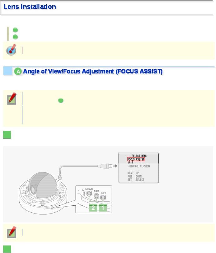
After installing the lens to the camera, you need to perform the following adjustments for the lens.
AAngle of View/Focus Adjustment (FOCUS ASSIST)
BIris Adjustment (IRIS)
Using network operation, you can use the focus assist function to adjust the focus.
Use the focus assist function to accurately focus on subject in high-resolution megapixel image because otherwise doing so would be extremely difficult.
When focus cannot be adjusted normally because the video images are too dark or too bright, adjust the lens iris first ( B ).
The focus must be readjusted if the camera has lost focus due to difference in the subject distance or ambient temperature, the deterioration of the lens and installation environment, and the like that have been caused over the years.
1  Press the SET button for 2 seconds or more.
The monitor now shows the SELECT MENU screen.
On the SELECT MENU screen, all information is displayed in English.
2  Select [FOCUS ASSIST] using the NEAR/FAR button and press the SET button.
The monitor now shows the focus adjustment screen.
Introduction 12/15
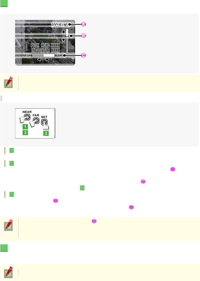
3  Adjust the lens orientation. Then adjust angle of view using the zoom ring, and the focus using the buttons.
PEAK HOLD: Shows the value of the maximum focus level.
INDICATOR: Shows the value of the current focus level.
Adjusting focus
1 Use the NEAR/FAR button to roughly focus on the subject.
Adjust by monitoring the video image on the monitor.
2 Press the SET button.
The camera automatically focuses on the subject. Note that the color of the status indicator ( A ) “FOCUSING” turns from black to orange.
If the camera fails to automatically focus on the object, the status indicator ( A ) will indicate “ERROR”. In this case, manually adjust the focus (in Step 3 ).
).
3 Press the NEAR/FAR button to adjust the focus.
Adjust to set the FA bar ( B  ) to the maximum level.
When the subject comes into focus, the color of the status indicator ( A  ) “FOCUSING” turns from black to orange.
Pressing the button causes the FB bar ( C ) gauge to move.
The position changes step by step each time the button is pressed and continuously at a high speed when the button is held down.
4  Press the SET button for 2 seconds or more.
The focus adjustment screen will close.
The focus adjustment screen will also close automatically if left idle for 5 minutes or more.
If video is out of focus in either color or black-and-white mode, adjust the focus in respective modes.
Introduction 13/15
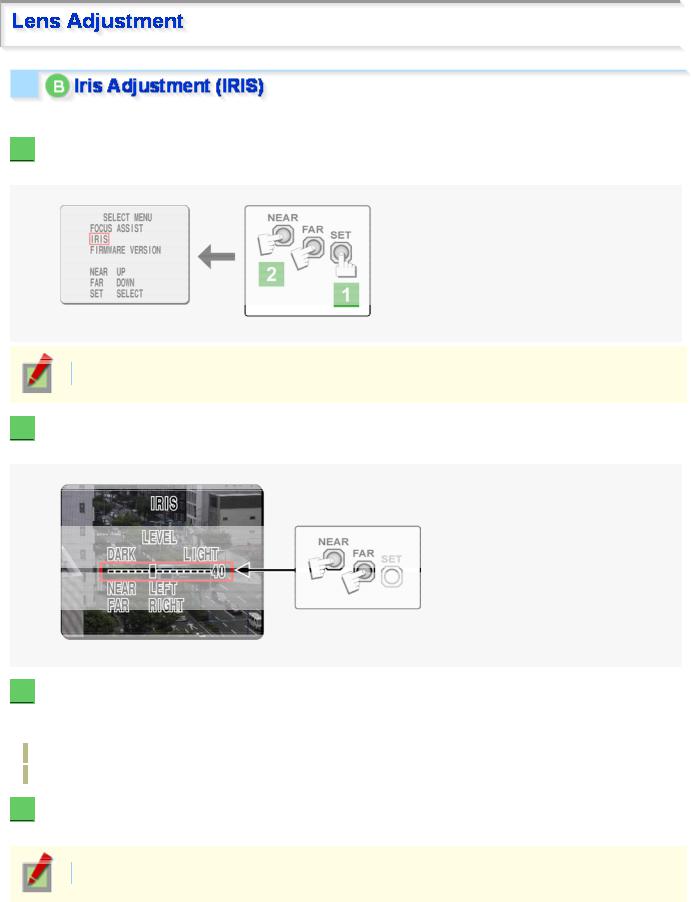
If the camera produces too dark, too bright, or other incorrect video images, adjust the lens iris.
1  Press the SET button for 2 seconds or more.
The monitor now shows the SELECT MENU screen.
On the SELECT MENU screen, all information is displayed in English.
2  Select [IRIS] using the NEAR/FAR button and press the SET button.
The monitor now shows the iris adjustment screen.
3  Press the NEAR/FAR button to adjust the iris level.
The position changes step by step each time the button is pressed and continuously at a high speed when the button is held down.
NEAR: Closes the iris to produce darker images.
FAR: Opens the iris to produce brighter images.
4  Press the SET button for 2 seconds or more.
The iris adjustment screen will be closed.
The iris adjustment screen will also close automatically if left idle for 5 minutes or more.
Introduction 14/15
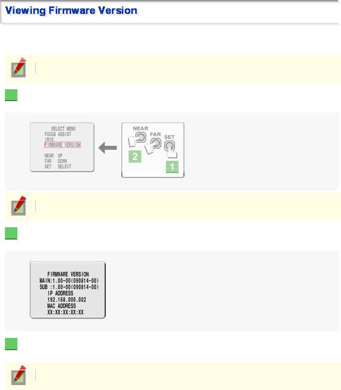
On the FIRMWARE VERSION screen, you can check the firmware version, IP address, and other information on the camera.
The firmware version can also be checked via network operation on the OPTION SETTINGS screen.
1  Press the SET button for 2 seconds or more.
The monitor now shows the SELECT MENU screen.
On the SELECT MENU screen, all information is displayed in English.
2  Select [FIRMWARE VERSION] using the NEAR/FAR button and press the SET button.
The monitor now shows the FIRMWARE VERSION screen.
3  Press the SET button for 2 seconds or more.
The FIRMWARE VERSION screen closes.
The FIRMWARE VERSION screen will close automatically if left idle for 5 minutes or more.
Introduction 15/15
VDC-HD3300/HD300P
VDC-HD3100/HD3100P
From Connection to Network Operation
Live Video Monitoring
Alarm Detection and Output
Software Information
Configuration menu quick reference tables
Quick Operation Guide1/10
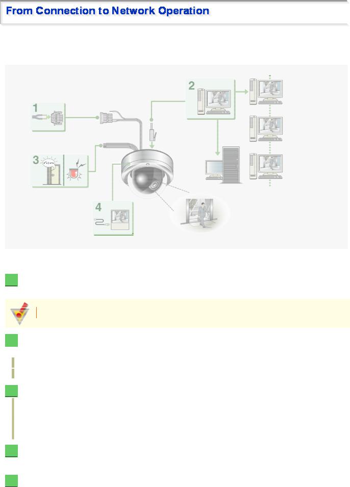
Follow the steps below to set up and connect the camera to your PC.
You can use alarm video recording, bidirectional audio communications, and other standard features of the camera, in addition to normal live video monitoring.
1  Connect the power cable to the power terminals.
Use a 24-VAC or 12-VDC power supply.
Do not turn on the camera until you complete all connections.
2  Connect the network (LAN) socket to your PC using a LAN cable.
Check the operating environment of your PC and perform the following operations: Check the network information on your PC.
Install the “H.264 Plug-in” from the supplied CD-ROM onto your PC.
3  Connect necessary external devices to the alarm input/output terminals.
ALARM IN1/2 terminal: Connect an external switch, infrared sensor, or other device to detect alarm conditions such as entry of an intruder.
ALARM OUT 1/2: Connect a buzzer, lamp, or other alarm device to output a signal to warn people of the occurrence of an alarm condition.
4  Connect a monitor for focus adjustment to the monitor output socket.
Connect your monitor to the camera via the supplied video cable.
5  Turn on the camera.
Live video appears on the monitor.
Quick Operation Guide 2/10
To enable surveillance with clear video images, adjust the lens focus while viewing the subject on the FOCUS ASSIST screen displayed on the monitor.
After adjustment, be sure to remove the monitor cable.
6  Access the camera from your PC's Web browser.
Live video appears on the live screen. Now, you can perform all network operations from your PC.
Quick Operation Guide 3/10

If you are operating the camera for the first time, check the factory default video/image conditions on the CODEC/STREAMING SETTINGS screen. Change the default settings as necessary.
For details, refer to the “CODEC/STREAMING SETTINGS” section.
16:9 (Default) → 4:3
You can switch between JPEG image and H.264 video using the buttons on the live screen control panel. The screenshot above shows the factory default settings for each video/image condition.
Quick Operation Guide 4/10
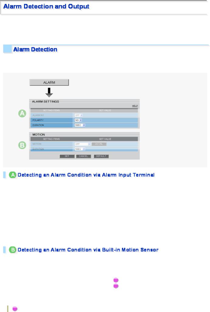
If you are operating the camera for the first time, check the factory default alarm detection conditions on the ALARM SETTINGS screen. Change the default settings as desired.
For details, refer to the “ALARM SETTINGS” section.
You can configure the camera to detect alarm conditions via the “alarm input terminals” or “built-in motion sensor”. For how to configure the camera to detect alarm conditions via the alarm input terminals, refer to the “Alarm Input/Output Terminal Connections” section.
Connecting an alarm switch, infrared sensor, or other external device to the ALARM IN1/2 terminal enables the camera to detect alarm conditions such as entry of an intruder.
Setting Item |
Default Setting |
Optional Setting |
|
|
|
ALARM IN1/2 (Alarm input |
OFF (Disables alarm detection.) |
ON (Enables alarm detection.) |
terminal number) |
|
|
|
|
|
POLARITY (Signal polarity) |
NO (Ex.: Detects an alarm when |
NC (Ex.: Detects an alarm when door is opened.) |
door is closed) |
|
|
|
|
|
|
|
|
DURATION (Alarm retention |
5SEC (Ex.: Records alarm video |
10SEC to 5MIN, CC (Retains the alarm state as long |
duration) |
for 5 sec.) |
as the alarm signal persists.) |
|
|
|
The camera uses the built-in motion sensor to detect alarm conditions.
The motion sensor detects an alarm condition in two ways as follows.
Setting Item |
Default Setting |
|
Optional Setting |
|
|
|
|
MOTION (Use of built-in |
OFF (Disables alarm |
A |
MASKING |
motion sensor) |
detection.) |
B |
DETECT |
|
|
|
|
DURATION (Alarm retention |
5SEC (Ex.: Records alarm |
10SEC to 5MIN, CC (Retains an alarm state as long as |
|
duration) |
video for 5 sec.) |
the motion alarm persists.) |
|
|
|
|
|
A Disabling motion detection in masked areas
Quick Operation Guide 5/10
B Detecting motion in specific areas
In [MOTION], after selecting a motion sensor type, click  DETAIL
  to configure the detection conditions on the detailed configuration screen.
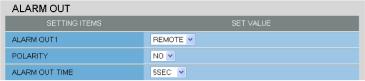
You can configure the camera to “automatically output alarm signals” or “remotely (manually) output alarm signals”.
You can configure the camera to automatically output an alarm signal when either of its alarm input terminals receives an alarm signal.
Setting Item |
Default Setting |
|
|
|
|
ALARM OUT1/ 2 (Alarm |
OFF (Disables alarm output.) |
|
output terminal number) |
|
|
|
|
|
POLARITY (Signal polarity) |
NO |
|
|
|
|
ALARM OUT TIME (Alarm |
5SEC (Ex.: Beeps a warning for 5 sec.) |
|
output time) |
|
|
|
|
|
ALARM IN (Output |
ALARM IN1 (Triggers alarm output when |
|
ALARM IN1 terminal receives an alarm |
||
condition) |
||
signal.) |
||
|
||
|
|
|
MOTION (Output condition) |
OFF (Disables alarm output using motion |
|
sensor.) |
||
|
||
|
|
Optional Setting
ON (Enables automatic alarm output.)
NC
10SEC to 5MIN
ALARM IN2 (Triggers alarm output when ALARM IN2 terminal receives an alarm signal.)
ON (Triggers alarm output using motion sensor.)
Use the Remote Alarm buttons (
 ) provided on the live screen to send alarm signals from the camera's alarm output terminals.
Quick Operation Guide 6/10
|
|
|
|
|
|
|
|
Setting Item |
Default Setting |
Optional Setting |
|
|
|
|
|
ALARM OUT1/ 2 (Alarm output |
OFF (Disables alarm |
REMOTE (Enables remote alarm output.) |
|
terminal number) |
output.) |
|
|
|
|
|
|
POLARITY (Signal polarity) |
NO |
NC |
|
|
|
|
|
ALARM OUT TIME (Alarm output |
5SEC (Ex.: Beeps a warning |
10SEC to 5MIN, CC (Stops alarm output when |
|
time) |
for 5 sec.) |
Remote Alarm button is clicked.) |
|
|
|
|
|
Quick Operation Guide 7/10
You can install the following software on your PC to extend the capabilities of your surveillance system.
The CD-ROM that comes with the camera includes all the supplied software.
A H.264 Plug-in (Plug-in for monitoring live video as high-quality moving images)
This plug-in software is required to display H.264 video on the live screen. Be sure to install it on each computer from which you access the camera via network operation.
B VA-SW3050Lite (Application for monitoring live video from more than one camera)
This monitoring application is designed for use with SANYO network cameras.
You can access up to 128 cameras simultaneously.
The application lets you monitor video images from connected cameras in either the single screen or the 4- screen, 9- screen, or 16-split screen mode.
C Auto IP Setup (Utility for automatically setting up IP addresses when two or more new cameras are connected)
This utility automatically assigns a unique IP address to each camera that has the factory default IP address (“192.168.0.2”).
Using the utility's camera search function, you can check the IP addresses of all cameras existing on the same local network.
It is also possible to check and correct overlapping IP addresses.
VA-SW3050Server/Client (Application for recording and playing back streaming images from camera)
This recorder/player application is designed for use with SANYO network cameras.
This is a complete version of the VA-SW3050 series software, which offers all the functions you need to perform monitoring, recording, search, playback, and other operations in a surveillance system.
This software requires at least two PCs that serve as the server and the client.
Quick Operation Guide 8/10
Click  MENU
MENU  on the control panel to display the administrator configuration menu that includes a series of menu selection buttons.
If you are a surveillance system administrator, use these buttons to configure necessary settings according to the installation environment and application of your camera.
Configuration Related to Network Connection
Operation |
Configuration Screen (Menu) |
|
|
Changing the camera's IP address. |
NETWORK SETTINGS |
|
|
Using SANYO's DDNS service. |
|
|
|
Using SSL communication. |
|
|
|
Streaming H.264 video in multicast |
|
|
|
Clock and Camera Title Configuration
Operation |
Configuration Screen (Menu) |
|
|
Adjusting clock to specific time based on external input signal |
CLOCK SETTINGS |
|
|
Configuring the camera title |
|
|
|
Configuration Related to Access and Security
Operation |
Configuration Screen (Menu) |
|
|
Changing the user password |
USER SETTINGS |
|
|
Allowing all users to access the camera without any authentication |
|
check |
|
|
|
Restricting PCs that have access to the camera |
SECURITY SETTINGS |
|
|
Configuration Related to Live Video
Operation |
Configuration Screen (Menu) |
|
|
Accessing the camera from video viewer or similar software to view |
NETWORK SETTINGS |
live video |
|
|
|
Hiding specific portions of video |
CAMERA SETTINGS (PRIVACY MASK) |
|
|
Alarm-Related Configuration
Operation |
Configuration Screen (Menu) |
|
|
Sending an alarm image via e-mail |
E-MAIL SETTINGS |
|
|
Using the alarm input terminals to switch the camera between the |
CAMERA SETTINGS (DAY/NIGHT) |
color and black-and-white video modes |
|
( (This function is supported only by VDC-HD3300P/VDC- |
|
HD3300.)) |
|
|
|
Recording-Related Configuration
Operation |
Configuration Screen (Menu) |
|
|
Recording images from the camera to an FTP server |
FTP SETTINGS |
|
|
Quick Operation Guide 9/10

Optional Configuration
Operation |
Configuration Screen (Menu) |
|
|
Updating the camera's firmware to the latest version. |
OPTION SETTINGS (FIRMWARE UPDATE) |
|
|
Restoring the factory default settings |
OPTION SETTINGS (FACTORY DEFAULT) |
|
|
Backing up or uploading settings |
OPTION SETTINGS (MENU BACKUP/MENU |
|
UPLOAD) |
|
|
Viewing the access log, system log, and operation log |
OPTION SETTINGS (LOG) |
|
|
Quick Operation Guide 10/10
VDC-HD3300/HD300P
VDC-HD3100/HD3100P
Preparing Your Computer for Network Operation Setting Up IP Addresses Automatically (Auto IP Setup) Checking the operating environment
Configue the network information on your PC Operation Privileges and Login Users
Before You Begin Network Operation1/13
Follow the steps below to prepare your computer for network operation. For detailed procedure, refer to the linked information.
1  Assign a unique IP address to each camera.
If you have newly installed two or more cameras on your network, you can accomplish this by using the supplied “Auto IP Setup” software.
2  Check your operating environment
3  Connect the camera to the network to which your PC is also connected.
4  Configue the network information on your PC
You need to configure information such as the IP address of your PC.
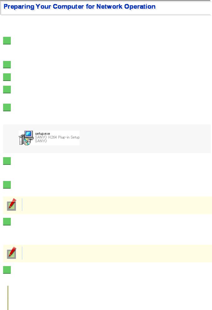
5  Install the “H.264 Plug-in” from the supplied CD-ROM onto your PC.
Double-click the “setup.exe” icon and complete the steps in the wizard.
You are now ready to monitor the surveillance video in the H.264 format.
6  Access the camera from your Web browser.
From your Web browser (Internet Explorer), access the camera and log into the system as an “admin” user (administrator).
7  Monitor live video.
When you access the camera and log into the system, live video from the camera appears on the live screen.
If the live screen displays no or distorted video, check your operating environment and connection conditions.
8  Configure the necessary settings on the administrator configuration screens.
Although the camera is already configured with the factory default settings so that you can monitor live video immediately after you log into the system, you need to configure necessary settings according to your installation environment and application of the camera.
If this is the first access to the camera, start by configuring the system clock on the CLOCK SETTINGS screen.
9  Use associated software applications to extend the capabilities of your surveillance system.
Install the following associated software applications on your PC, as required:
VA-SW3050Lite (supplied): Monitor application for monitoring video images from more than one camera simultaneously on a multi-view screen.
VA-SW3050Server/Client (optional): Recorder/player application for recording and playing back streaming video data from the network.
Before You Begin Network Operation 2/13
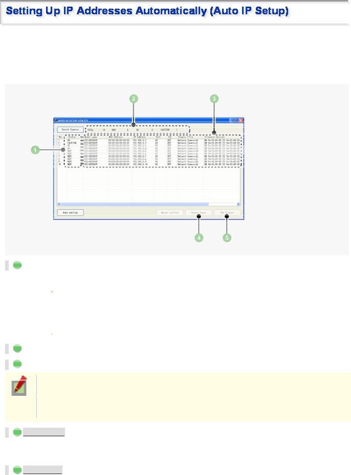
If you are installing two or more new cameras on the same local network, you need to change the factory default IP address of each camera to prevent IP address overlap. The supplied “Auto IP Setup” software frees you from this burden by automatically assigning a unique IP address to each camera on your network.
Before setting up the IP addresses automatically, click the [Search Cameras] button in the utility window to search all cameras on the network and display the address settings and details of each camera.
1 Status
NEW: The camera has the default IP address (“192.168.0.2”).
 Assign a unique IP address.
OK: The camera has a unique IP address and can be connected successfully to network.
CAUTION: The camera cannot be connected successfully to the network because of IP address overlap or other reason.
 Change the IP address.
2 Number of searched cameras (Total and by status)
3 Camera details
“Model name”, “IP Address”, “Port”, “SSL”, “Camera Title”, and “Firmware Version” are not shown if the network board or other hardware is not supported.
“IP Address”, “Port”, “SSL”, and “Camera Title” are editable. (Refer to the “Manually Setting Up IP Addresses of Existing Cameras” section.)
4  Camera Image
  button
Select the desired camera row and click this button. Then, video from the camera appears in a separate window. Use it to check which camera is selected or when editing the camera title or other data.
5  Web Browser
  button
Select the desired camera row and click this button. Then, the Web browser opens and connects to the camera automatically.
Before You Begin Network Operation 3/13

1  Insert the supplied CD-ROM into the CD-ROM drive of your PC.
The opening menu appears.
2  Click [Auto IP Setup].
The utility window opens so that you can search cameras.
If you encounter a firewall confirmation dialog box, disable the firewall so that your PC can communicate with the camera.
3 Click  Search Cameras
  .
.
The utility searches all cameras on the local network and shows information on each camera one after another.
The above screenshot shows an example when your PC is connected to 10 cameras.
4  Click
Click  Auto setting
  and, in the address range selection dialog box, click
  EXECUTE
  .
.
The utility automatically assigns a series of new IP addresses, starting from the start address.
The dialog box initially shows, as the start IP address, the IP address to be assigned to the first camera that has a status of “NEW”.
To specify your own address range, type both the start and end IP addresses.
The utility automatically assigns an IP address to each camera located in the LAN, but not beyond the router.
It skips any IP address that is already used.
If you find that the searched cameras have overlapping IP addresses (indicated by a status of “CAUTION”) or if you need to change a camera title, you can edit the displayed camera data manually as described below.
Before You Begin Network Operation 4/13
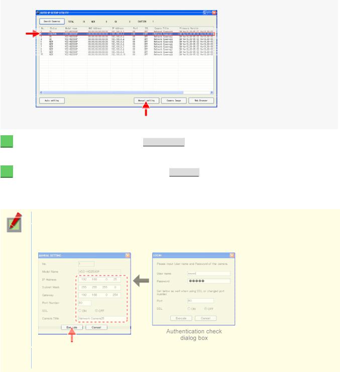
1  Select the desired camera and click
  Manual setting
  .
.
The camera information dialog box opens.
2  Make changes to the camera data and click
  EXECUTE
  .
.
This transmits your changes to the camera.
You can see the problem of IP address overlap has been resolved in the [Status] row of the list, which has been changed from “CAUTION” to “OK”.
You cannot change the model name.
If your login user name and password has been changed from the factory default settings, you will be presented with an authentication check dialog box. In this case, type the current user name and password.
If SSL communication is enabled for the selected camera, you cannot edit the camera data. Change the SSL and port number settings in the authentication check dialog box.
Before You Begin Network Operation 5/13
 Loading...