


Sanyo KH2442, XH4242, KH3642, CH4242, UH2442 User Manual
...INSTALLATION INSTRUCTION
— Split System Heat Pump Air Conditioner —
Model Combinations
Combine indoor and outdoor units only as listed below.
Indoor Units and Outdoor Units
|
Indoor Units Type |
24 |
|
|
36 |
|
|
|
|
42 |
|
|
|
|
|
|
|
|
|
|
|
|
|
1 |
4-Way Air Discharge |
XH2442 |
|
|
XH3642 |
|
|
|
XH4242 |
||
X |
Semi-Concealed |
(PNR-XH2442) |
|
|
(PNR-XH3642) |
|
|
(PNR-XH3642) |
|||
(Matching Ceiling Panel) |
|
|
|
|
|||||||
|
|
|
|
|
|||||||
|
|
|
|
|
|
|
|
|
|
|
|
|
|
|
|
|
|
|
|
|
|
|
|
2 |
Wall-Mounted |
KH2442 |
|
|
KH3642 |
|
|
|
|
|
|
K |
|
|
|
|
|
|
|
||||
|
|
|
|
|
|
|
|
|
|
|
|
3 |
Ceiling-Mounted |
TH2442 |
|
|
TH3642 |
|
|
|
TH4242 |
||
T |
|
|
|
|
|
|
|
|
|
|
|
|
|
|
|
|
|
|
|
|
|
|
|
4 |
Concealed-Duct |
UH2442 |
|
|
UH3642 |
|
|
|
|
|
|
U |
|
|
|
|
|
|
|
|
|
|
|
|
|
|
|
|
|
|
|
|
|
|
|
|
|
|
|
|
|
|
|
|
|
|
|
5 |
Outdoor Units |
CH2442 |
|
|
CH3642 |
|
|
|
CH4242 |
||
C |
|
|
|
|
|
||||||
|
|
|
|
|
|
|
|
|
|
||
|
|
|
|
|
|
||||||
6 |
Wired Remote Controller |
|
RCS-SH80UG (Optional part ) |
|
|
||||||
|
|
|
|
|
|
|
|||||
7 |
Wireless Remote Controller |
Built-in type: RCS-SH80UA.WL (Optional part ) |
|
||||||||
External type: RCS-BH80UA.WL (Optional part ) |
|
||||||||||
|
|
|
|||||||||
|
|
|
|
|
|
|
|
||||
8 |
Weekly Timer |
|
TM-SH80UG (Optional part ) |
|
|
||||||
|
|
|
|
|
|
|
|
||||
9 |
System Controller |
|
SHA-KC64UG (Optional part ) |
|
|
||||||
|
|
|
|
|
|
|
|
|
|
|
|
|
|
|
|
|
|
|
|
|
|
|
|
|
|
|
|
OPERATING LIMITS |
|
|
|
|
|
||
|
|
|
|
|
|
|
|
|
|
||
|
|
|
|
■ Maximum Conditions |
|
Cooling |
/ |
Heating |
|||
|
|
|
|
|
Outdoor temperature : |
115°F DB |
/ |
65°F WB |
|||
|
|
|
|
|
Room temperature |
: |
71°F WB |
/ |
80°F DB |
||
|
|
|
|
■ Minimum Conditions |
|
|
|
|
|
||
|
|
|
|
|
Outdoor temperature : |
23°F (0°F)* DB / |
15°F WB |
||||
|
|
|
|
|
Room temperature |
: |
57°F WB |
/ |
59°F DB |
||
|
|
|
|
|
|
|
|||||
|
|
|
* When air discharge chamber is installed. |
|
|||||||
|
|
|
|
|
|||||||
|
|
|
|
Units should be installed by licensed contractor according |
|||||||
|
|
|
|
to local code requirements. |
|
|
|
|
|||
|
|
|
|
|
|
|
|
|
|
|
|
1
X
2
K
3
T
4
U
5
C
6
RC (WD)
7
RC (WL)
8
WT
9
SC
|
SANYO FISHER COMPANY |
In Canada |
|
A DIVISION OF SANYO NORTH |
SANYO Canada Inc. |
|
AMERICA CORPORATION |
300 Applewood Crescent |
|
21605 Plummer Street |
Concord, Ontario |
85464359146001 © SANYO 2001 |
Chatsworth, CA91311 |
L4K 5C7, Canada |
Important
Please Read Before Starting
This air conditioning system meets strict safety and operating standards. As the installer or service person, it is an important part of your job to install or service the system so it operates safely and efficiently.
For safe installation and trouble-free operation, you must :
ÚCarefully read this instruction booklet before beginning.
ÚFollow each installation or repair step exactly as shown.
ÚObserve all local, state, and national electrical codes.
ÚPay close attention to all warning and caution notices given in this manual.
This symbol refers to a hazard or unsafe practice which can result in severe personal injury or death.
This symbol refers to a
hazard or unsafe practice
CAUTION which can result in personal injury or product or property damage.
If Necessary, Get Help
These instructions are all you need for most installation sites and maintenance conditions. If you require help for a special problem, contact our sales/service outlet or your certified dealer for additional instructions.
In Case of Improper Installation
The manufacturer shall in no way be responsible for improper installation or maintenance service, including failure to follow the instructions in this document.
SPECIAL PRECAUTIONS
When Wiring
……………………………………………………………………
ELECTRICAL SHOCK CAN CAUSE SEVERE PERSONAL INJURY OR DEATH. ONLY A QUALIFIED, EXPERIENCED ELECTRICIAN SHOULD ATTEMPT TO WIRE THIS SYSTEM.
•Do not supply power to the unit until all wiring and tubing are completed or reconnected and checked.
•Highly dangerous electrical voltages are used in this system. Carefully refer to the wiring diagram and these instructions when wiring. Improper connections and inadequate grounding can cause accidentaly injury or death.
•Ground the unit following local electrical codes.
•Connect all wiring tightly. Loose wiring may cause overheating at connection points and a possible fire hazard.
When Transporting
……………………………………………………………………
Be careful when picking up and moving the indoor and outdoor units. Get a partner to help, and bend your knees when lifting to reduce strain on your back. Sharp edges or thin aluminum fins on the air conditioner can cut your fingers.
When Installing
……………………………………………………………………
…In a Room
Properly insulate any tubing run inside a room to prevent “sweating” that can cause dripping and water damage to walls and floors.
…In Moist or Uneven Locations
Use a raised concrete pad or concrete blocks to provide a solid, level foundation for the outdoor unit. This prevents water damage and abnormal vibration.
…In an area with High Winds
Securely anchor the outdoor unit down with bolts and a metal frame. Provide a suitable air baffle.
…In a Snowy Area (for Heat Pump-type Systems)
Install the outdoor unit on a raised platform that is higher than drifting snow. Provide snow vents.
When Connecting Refrigerant Tubing
……………………………………………………………………
•Ventilate the room well, in the event that refrigerant gas leaks during the installation. Be careful not to allow contact of the refrigerant gas with a flame as this will cause the generation of poisonous gas.
•Keep all tubing runs as short as possible.
•Use the flare method for connecting tubing.
•Apply refrigerant lubricant to the matching surfaces of the flare and union tubes before connecting them, then tighten the nut with a torque wrench for a leak-free connection.
•Check carefully for leaks before starting the test run.
NOTE
Depending on the system type, liquid and gas lines may be either narrow or wide. Therefore, to avoid confusion the refrigerant tubing for your particular model is specified as either “narrow” or “wide” rather than as “liquid” or “gas”.
When Servicing
……………………………………………………………………
•Turn the power OFF at the main power box (mains) before opening the unit to check or repair electrical parts and wiring.
•Keep your fingers and clothing away from any moving parts.
•Clean up the site when installation is finished. Check that no metal scraps or bits of wiring have been left inside the unit.
CAUTION
•Ventilate any enclosed areas when installing or testing the refrigeration system. Contact of refrigerant gas with fire or heat can produce poisonous gas.
•Confirm after installation that no refrigerant gas is leaking. If the gas comes in contact with a burning stove, gas water heater, electric room heater or other heat source, it can cause the generation of poisonous gas.
i

 CONTENTS
Page |
|
Page |
IMPORTANT |
3-25. |
Checking the Drainage |
Please Read Before Starting |
3-26. |
Increasing the Fan Speed |
1. GENERAL ................................................................... |
4 |
1-1. Tools Required for Installation (Not Supplied)
1-2. Accessories Supplied with Unit
1-3. Type of Copper Tube and Insulation Material 1-4. Additional Materials Required for Installation 1-5. Tubing Length
2. |
SELECTING THE INSTALLATION SITE .................. |
10 |
|
|
Indoor Unit |
|
|
|
Outdoor Unit |
|
|
|
2-1. |
Air Discharge Chamber for Top Discharge |
|
|
2-2. |
Installing the Outdoor Unit in Heavy Snow Areas |
|
|
2-3. |
Precautions When Installing in Heavy Snow Areas |
|
|
2-4. |
Dimensions of Snow / Wind-proof Ducting and |
|
|
|
Refrigerant Tubing Space for Installation |
|
3. |
HOW TO INSTALL THE INDOOR UNIT .................... |
14 |
|
■4-Way Air Discharge Semi-Concealed Type
|
(XH Type) ................................................................... |
14 |
|
|
3-1. |
Suspending the Indoor Unit |
|
|
3-2. |
Preparation for Suspending |
|
|
3-3. |
Placing the Unit Inside the Ceiling |
|
|
3-4. |
Installing the Drain Piping |
|
|
3-5. |
Checking the Drainage |
|
|
3-6. |
Before Installing the Ceiling Panel |
|
|
3-7. |
Installing the Ceiling Panel |
|
|
3-8. |
When Removing the Ceiling Panel for Servicing |
|
|
3-9. |
Duct for Fresh Air |
|
■ |
Wall-Mounted Type (KH Type) ................................... |
22 |
|
|
3-10. |
Removing the Wall Fixture from the Unit |
|
|
3-11. |
Selecting and Making a Hole |
|
|
3-12. Installing the Wall Fixture onto Wooden or |
|
|
|
|
Gypsum Wall |
|
|
3-13. |
Removing the Casing to Install the Indoor Unit |
|
|
3-14. |
Preparing the Indoor Side Tubing |
|
|
3-15. |
Wiring Instructions |
|
|
3-16. |
Wiring Instructions for Inter-Unit Connections |
|
|
3-17. |
Shaping the Tubing |
|
|
3-18. |
Installing the Drain Hose |
|
■ |
Ceiling-Mounted Type (TH Type). .............................. |
31 |
|
|
3-19. |
Suspending the Indoor Unit |
|
|
3-20. |
Duct for Fresh Air |
|
|
3-21. |
Installing the Drain Piping |
|
■ |
Concealed-Duct Type (UH Type) ............................... |
35 |
|
|
3-22. |
Required Minimum Space for Installation and Service |
|
|
3-23. |
Suspending the Indoor Unit |
|
|
3-24. |
Installing the Drain Piping |
|
4. HOW TO INSTALL THE OUTDOOR UNIT ................ |
40 |
4-1. Removing the Protective Spacer for Transportation
4-2. Installing the Outdoor Unit |
|
|
4-3. |
Tubing Direction |
|
5. ELECTRICAL WIRING ............................................. |
41 |
|
5-1. |
General Precautions on Wiring |
|
5-2. Recommended Wire Length and Wire Diameter |
||
|
for Power Supply System |
|
5-3. |
Wiring System Diagrams |
|
5-4. |
How to Connect Wiring to the Terminal |
|
6.HOW TO INSTALL THE WIRED REMOTE CONTROLLER
(OPTIONAL PART) .................................................... |
45 |
|
6-1. Installation site selection |
|
|
6-2. |
Wired Remote Controller Installation |
|
6-3. Basic Wiring Diagram |
|
|
6-4. Wiring System Diagram for Group Control |
|
|
6-5. |
Wiring System Diagram for Multiple Remote |
|
|
Control |
|
6-6. |
How to Switch the Indoor Temperature Sensor |
|
6-7. |
Explanation of Alarm Messages |
|
7.HOW TO INSTALL THE WIRELESS REMOTE CONTROLLER
(OPTIONAL PART) .................................................... |
52 |
7-1. Wireless Remote Controller Installation
7-2. Room Temperature Sensor Setting
7-3. Address Switches
7-4. Setting the Model Code
<RCS-SH80UA. WL>
■4-Way Air Discharge Semi-concealed Type
(XH Type) ................................................................... |
54 |
|
7-5. |
Indicator section Installation |
|
7-6. |
Operating Controller Installation |
|
■ Ceiling Mounted Type (TH Type) ......................... |
55 |
|
7-7. |
Indicator Section Installation |
|
7-8. |
Operating Controller Installation |
|
7-9. |
Electrical Wiring |
|
7-10. |
Test Run Switch |
|
7-11. |
Misoperation Alarm Indicators |
|
<RCS-BH80UA.WA> |
|
|
7-12. |
Separate type Signal Receiving Unit Installation |
|
7-13. |
Electrical Wiring |
|
7-14. |
Test Run Switch |
|
7-15. |
Misoperation Alarm Indicators |
|
7-16. |
Basic Wiring Diagram |
|
7-17. |
Wiring System Diagram for Group Control |
|
7-18. |
Wiring System Diagram for Multiple |
|
Page
8.HOW TO INSTALL THE WEEKLY TIMER
(OPTIONAL PART) ................................................... |
65 |
8-1. Mounting Dimensions for Continuous Installation 8-2. When Using a Wall Box for Flush Mounting
8-3. Wiring Diagram
8-4. Test Run Setting
8-5. Memory Back Up Function for Power Failure Compensation
9.HOW TO INSTALL THE SYSTEM CONTROLLER
(OPTIONAL PART) ................................................... |
67 |
|
9-1. System Controller Installation |
|
|
9-2. |
Electrical Wiring |
|
9-3. Address Switch Setting |
|
|
9-4. |
Mode Setting |
|
9-5. How to Perform Zone Registration |
|
|
9-6. Connection with Other Equipments |
|
|
9-7. |
Memory Back Up Switch |
|
9-8. |
Test Run |
|
10. HOW TO PROCESS TUBING .................................. |
79 |
|
10-1. Use of the Flaring Method
10-2. Flaring Procedure with a Flare Tool
10-3. Precaution before Connecting Tubes Tightly
10-4. Precautions during Brazing
10-5. Connecting Tubing between Indoor and Outdoor Units
10-6. Insulating the Refrigerant Tubing
10-7. Taping the Tubes
10-8. Finishing the Installation
11. AIR PURGING .......................................................... |
82 |
|
12. TEST RUN ................................................................ |
85 |
|
12-1. |
Preparing for Test Run |
|
12-2. |
PCB Setting |
|
12-3. |
R.C. Address Setting Method |
|
12-4. |
Automatic Address Setting Method |
|
12-5. |
Displaying Indoor / Outdoor Unit Combination |
|
|
Numbers |
|
12-6. |
Test Run Procedure |
|
12-7. |
Items to Check Prior to Test Run |
|
12-8. |
The Main Alarms of Mis-wiring & Mis-setting |
|
12-9. |
The Main Alarms of Unit Troubles |
|
12-10. |
The Main Alarms of Power Supply Troubles |
|
13. PUMP DOWN ............................................................ |
93 |
1. GENERAL
This booklet briefly outlines where and how to install the air conditioning system. Please read over the entire set of instructions for the indoor and outdoor units and make sure all accessory parts listed are with the system before beginning.
1-1. Tools Required for Installation (Not Supplied)
1.Standard screwdriver
2.Phillips head screwdriver
3.Knife or wire stripper
4.Tape measure
5.Level
6.Sabre saw or key hole saw
7.Hacksaw
8.Core bits
9.Hammer
10.Drill
11.Tube cutter
12.Tube flaring tool
13.Torque wrench
14.Adjustable wrench
15.Reamer (for deburring)
1-2. Accessories Supplied with Unit
See Table 1-1 to 1-9.
Table |
Type |
|
|
1-1 |
4-Way Air Discharge Semi-Concealed |
|
|
1-2 |
Wall-Mounted |
|
|
1-3 |
Ceiling-Mounted |
|
|
1-4 |
Concealed-Duct |
|
|
1-5 |
Outdoor Unit |
|
|
1-6 |
Wired Remote Controller |
|
|
1-7 |
Wireless Remote Controller |
|
|
1-8 |
Weekly Timer |
|
|
1-9 |
System Controller |
|
|
1-3. Type of Copper Tube and Insulation Material
Copper tubing for connecting the outdoor unit to the indoor unit is available in kits which contain the narrow and wide tubing, fittings and insulation. Consult your nearest sales outlet or A/C workshop.
If you wish to purchase these materials separately from a local source, you will need:
1.Deoxidized annealed copper tube for refrigerant tubing.
2.Foamed polyethylene insulation for copper tubes as required to precise length of tubing. Wall thick-
ness of the insulation should be not less than 5/16 in..
3.Use insulated copper wire for field wiring. Wire size varies with the total length of wiring. Refer to Section 5. “Electrical Wiring” for details.
Check local electrical codes CAUTION and regulations before
obtaining wire. Also, check any specified instructions or limitations.
1-4. Additional Materials Required for Installation
1.Refrigeration (armored) tape
2.Insulated staples or clamps for connecting wire (See your local codes.)
3.Putty
4.Refrigeration tubing lubricant
5.Clamps or saddles to secure refrigerant tubing
6.Scale for weighing
4 S4359146
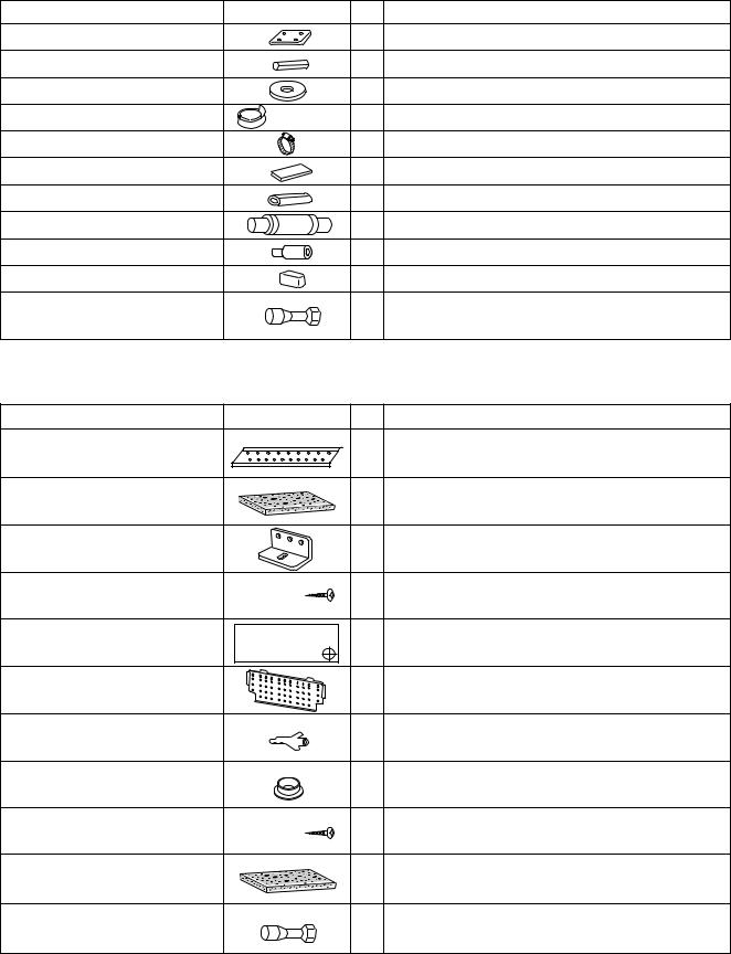
Table 1-1 XH (4-Way Air Discharge Semi-Concealed)
Part Name |
Figure |
Q’ty |
Remarks |
Full-scale installation diagram |
|
1 |
For determining suspension bolt pitch |
Flare insulator |
|
2 |
For wide and narrow tubes |
Washer |
|
8 |
For suspending indoor unit from ceiling |
Insulating tape |
(White) |
1 |
For wide tube flare nuts |
Hose band |
|
2 |
For securing drain hose |
Packing |
|
1 |
For drain joint |
Drain insulator |
|
1 |
For drain joint |
Drain hose |
|
1 |
|
Drain hose adaptor |
|
1 |
For drain outlet |
Sealing putty |
|
1 |
For sealing recessed portion of power supply |
Tube connector |
|
1 |
For sizing up of narrow tube from 1/4 in. to 3/8 in. |
|
(only for 24 type) |
||
|
|
|
|
Table 1-2 KH (Wall-Mounted) |
|
|
|
Part Name |
Figure |
Q’ty |
Remarks |
Wall fixture *1 |
|
1 |
For supporting the indoor unit |
Insulator *1 |
|
1 |
For insulation of the tubing of the indoor unit |
Mounting plate *1 |
|
1 |
For securing the indoor unit |
Tapping screw *1 |
Truss-head |
20 |
For fixing the wall fixture |
Phillips |
|||
|
4 × 1 in. |
|
|
Full-scale diagram |
|
1 |
For determining the place where the indoor unit is |
|
installed |
||
|
|
|
|
Wall fixture *2 |
|
1 |
For supporting the indoor unit |
Rawl plug *2 |
|
10 |
For fixing the wall fixture |
Cover *2 |
|
1 |
For improved tubing appearance |
Tapping screw *2 |
Truss-head |
10 |
For fixing the wall fixture |
Phillips |
|||
|
4 × 5/8 in. |
|
|
Insulator |
|
1 |
For insulation of the tubing of the indoor unit |
Tube connector |
|
1 |
For sizing up of narrow tube from 1/4 in. to 3/8 in. |
|
(only for 24 type) |
||
|
|
|
|
* 1 KH3642 only |
|
|
|
* 2 KH2442 only |
|
|
|
5 S4359146

Table 1-3 TH (Ceiling-Mounted)
Part Name |
|
Figure |
Q’ty |
|
Remarks |
|
Special washer |
|
|
4 |
|
For temporarily suspending |
|
|
|
|
indoor unit from ceiling |
|||
|
|
|
|
|||
Drain insulator |
|
|
1 |
For drain hose joint |
||
Flare insulator |
T5 |
T3 |
1 Set For wide tube joints |
|||
Drain hose adaptor |
|
|
1 |
|
|
|
Drain hose clamp |
|
|
4 |
|
|
|
Insulating tape |
|
Black |
2 |
|
For wide tube and drain hose joint |
|
|
White |
1 |
|
|
|
|
|
|
|
For wide flare joints |
|||
|
|
(heat-resisting) |
|
|||
Vinyl clamp |
|
|
2 |
For ends of flare insulator |
||
Full-scale installation |
|
|
1 |
|
For determining suspension |
|
diagram |
|
|
|
bolt pitch |
||
|
|
|
|
|||
Sealing putty |
|
|
1 |
For sealing recessed portion of power supply |
||
Drain hose |
|
|
1 |
|
|
|
Tube connector |
|
|
1 |
|
For sizing up of narrow tube from 1/4 in. to 3/8 in. |
|
|
|
|
(only for 24 type) |
|||
|
|
|
|
|
||
Table1-4 UH (Concealed-Duct) |
|
|
|
|
|
|
Part Name |
|
Figure |
|
Q’ty |
Remarks |
|
Flare insulator |
|
|
|
2 |
|
For wide and narrow tubes |
Insulating tape |
|
(Black) |
|
2 |
|
For wide and narrow tubes |
|
(White) |
|
2 |
|
For wide and narrow tube flare nuts |
|
|
|
|
|
|||
Tapping screw TOTA4-10 |
|
|
14 or 20 or 24 For air intake duct connection |
|||
Jumper cable* |
|
|
|
1 |
|
For increasing the fan speed |
Hose band |
|
|
|
1 |
|
For securing drain hose |
Packing |
|
|
|
1 |
|
For drain joint |
Sealing putty |
|
|
|
1 |
|
For sealing recessed portion of power supply |
Drain insulator |
|
|
|
1 |
|
For drain joint |
Drain hose |
|
|
|
1 |
|
|
Drain hose adaptor |
|
|
|
1 |
|
|
Clamp |
|
|
|
9 |
|
For securing drain hose & refrigerant tubing |
Tube connector |
|
|
|
1 |
|
For sizing up of narrow tube from 1/4 in. to 3/8 in. |
|
|
|
|
(only for 24 type) |
||
|
|
|
|
|
|
|
*Jumper cable is housed inside the electrical component box.
Table 1-5 (Outdoor Unit)
Part Name |
|
|
|
Figure |
Q’ty |
Remarks |
|||||||||
|
|
|
|
|
|
|
|
|
|
|
|
|
|
|
|
Hexagonal Wrench |
|
|
|
|
|
|
|
|
|
|
|
|
|
1 |
To open and shut the Narrow Tube Service Valve |
|
|
|
|
|
|
|
|
|
|
|
|
|
|
|
|
Grommet |
|
|
|
|
|
|
|
|
|
|
|
|
|
1 |
For protecting refrigerant pipe by attaching to the |
|
|
|
|
|
|
|
|
|
|
|
|
|
edge of Tubing Outlet |
||
|
|
|
|
|
|
|
|
|
|
|
|
|
|||
|
|
|
|
|
|
|
|
|
|
|
|
|
|
|
|
Bushing |
|
|
|
|
|
|
|
|
|
|
|
|
|
1 |
For protecting inter-unit control line by attaching to |
|
|
|
|
|
|
|
|
|
|
|
|
|
the edge of wiring outlet |
||
|
|
|
|
|
|
|
|
|
|
|
|
|
|
|
|
Installation Instruction |
|
|
|
|
|
|
|
|
|
|
|
|
|
1 |
|
|
|
|
|
|
|
|
|
|
|
|
|
|
|
|
|
Owner’s manual |
|
|
|
|
|
|
|
|
|
|
|
|
|
1 |
|
|
|
|
|
|
|
|
|
|
|
|
|
|
|
|
|
6 S4359146
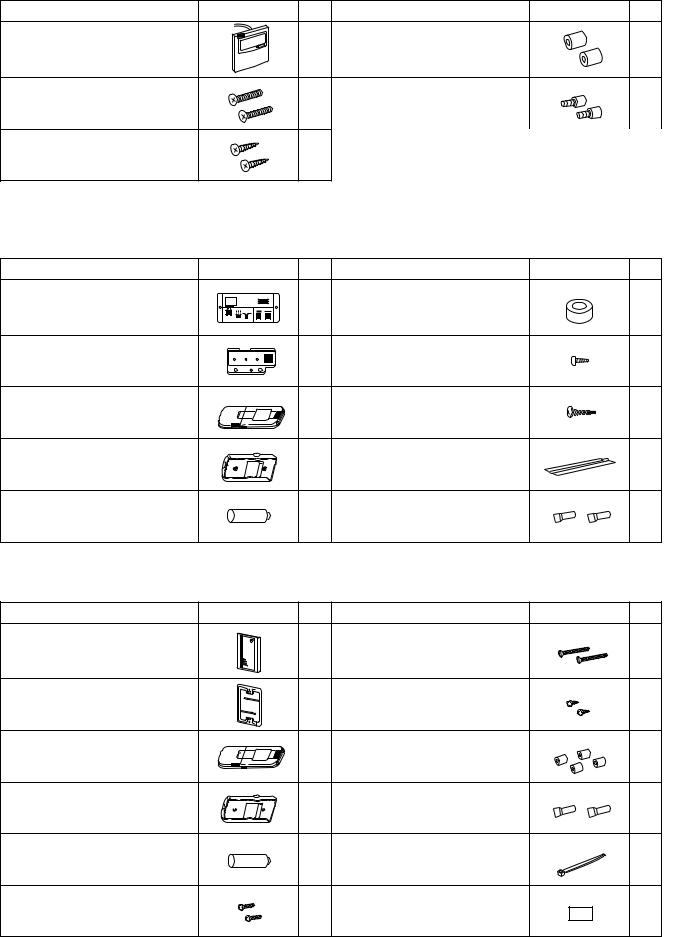
Table 1-6 (Accessories for the Wired Remote Controller)
Part Name |
Figure |
Q’ty |
Part Name |
Figure |
Q’ty |
Wired remote controller |
|
1 |
Spacers |
|
2 |
(comes with 7-7/8 in. wire) |
|
|
|||
|
|
|
|
|
|
Machine screws |
|
2 |
Wire joints |
|
4 |
M4 × 1 in. |
|
|
|||
|
|
|
|
|
|
Wood screws |
|
2 |
|
|
|
Table 1-7 (Accessories for the Wireless Remote Controller)
<RCS-SH80UA.WL>
Part Name |
Figure |
Q’ty |
Part Name |
Figure |
Q’ty |
Operation controller |
|
1 |
Spacers |
|
2 |
Indicator section |
Run Timer Heating preparations |
1 |
Pan-head tapping screws |
|
4 |
|
|
|
4 × 13/32 in. |
|
|
Wireless remote controller |
|
1 |
Truss-head tapping screws |
|
2 |
|
4 × 5/8 in. |
|
|||
|
|
|
|
|
|
Wireless remote controller |
|
1 |
Vinyl clampers |
|
3 |
mounting cradle |
|
L 5-29/32 |
|
||
|
|
|
|
||
Batteries |
|
2 |
Wire joints |
|
4 |
<RCS-BH80UA.WL>
Part Name |
Figure |
Q’ty |
Part Name |
Figure |
Q’ty |
Separate type signal receiving unit |
|
1 |
Small screws |
|
2 |
(comes with 7-7/8 in. wire) |
|
M4 × 1-9/16 in. |
|
||
|
|
|
|
||
Carrier for ceiling installation |
|
1 |
Wood screws |
|
2 |
Wireless remote controller |
|
1 |
Spacers |
|
4 |
Wireless remote controller |
|
1 |
Wire joints |
|
4 |
mounting cradle |
|
|
|||
|
|
|
|
|
|
Batteries |
|
2 |
Clamper |
|
1 |
Machine screws |
|
2 |
Ceiling installation paper pattern |
|
1 |
M4 × 1 in. |
|
(3-3/4 × 2-1/32 in.) |
|
||
|
|
|
|
7 S4359146
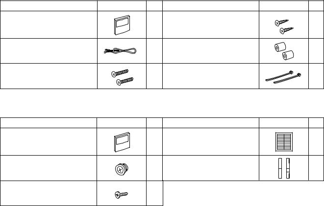
Table 1-8 (Accessories for the Weekly Timer)
Part Name |
Figure |
Q’ty |
Part Name |
Figure |
Q’ty |
Weekly timer |
|
1 |
Wood screws |
|
2 |
Connecting wiring |
|
1 |
Spacers |
|
2 |
length 4 ft. |
|
|
|||
|
|
|
|
|
|
Machine screws |
|
2 |
Clampers |
|
2 |
M4 × 1 in. |
|
|
|||
|
|
|
|
|
|
Table 1-9 (Accessories for the System Controller) |
|
|
|
||
Part Name |
Figure |
Q’ty |
Part Name |
Figure |
Q’ty |
|
|
|
|
SYSTEM CONTROLLER IDENTIFICATION LABEL |
|
|
|
|
Label |
ALL Central Control ALL RCU. |
|
|
|
|
ZONE1 Central Control ZONE1 RCU. |
|
|
System controller |
|
1 |
ZONE2 Central Control ZONE2 RCU. |
1 |
|
|
ZONE3 Central Control ZONE3 RCU. |
||||
|
|
|
ZONE4 Central Control ZONE4 RCU. |
|
|
|
|
|
(Identification label) |
|
|
Rubber bushing |
|
4 |
Label |
|
1 |
(7/8 in.) |
|
(Terminal base label) |
|
||
|
|
|
|
||
Screws for fixture |
|
2 |
|
|
|
(1-3/16 in.) |
|
|
|
|
|
|
|
|
|
|
|
8 S4359146
1-5. Tubing Length
●Refrigerant tubing between the indoor and outdoor units should be kept as short as possible.
●Select and decide the installation location so that the length of the refrigerant tubing will be within the limits given in Table 1-10.
|
INDOOR |
|
Tubing length (L) |
|||||||
|
UNIT |
|
|
|
|
|
|
|
|
|
|
|
|
|
|
|
|
|
|
||
|
|
|
|
|
||||||
Elevation difference (H) |
|
OUTDOOR |
|
|||||||
|
|
|
|
|
UNIT |
|
||||
|
|
|
|
|
|
|
|
|
|
|
|
|
|
|
|
|
|
|
|
|
|
0711_M_I
Fig. 1-1
Table 1-10 |
|
|
|
|
|
|
|
|
|
|
|
Models |
|
CH2442 |
|
CH3642, CH4242 |
|
|
|
|
|
|
||||
Tubing Data |
|
|
|
|
|
|||
|
|
|
|
|
|
|
||
|
|
|
|
|
|
|
|
|
Tubing size |
|
Narrow tube |
in. (mm) |
|
1/4 (6.35) |
|
3/8 (9.52) |
|
outer dia. |
Wide tube |
in. (mm) |
|
3/4 (19.05) |
|
3/4 (19.05) |
||
|
|
|
|
|
|
|
|
|
Limit of tubing length |
|
|
(ft.) |
|
165 |
|
165 |
|
|
|
|
|
|
|
|
||
Limit of elevation |
Outdoor unit is higher |
|
165 |
|
165 |
|||
than indoor unit |
(ft.) |
|
|
|||||
difference between |
|
|
|
|
|
|||
|
|
|
|
|
|
|
|
|
|
Outdoor unit is lower |
|
|
|
|
|||
the 2 units |
|
100 |
|
100 |
||||
than indoor unit |
(ft.) |
|
|
|||||
|
|
|
|
|
|
|||
|
|
|
|
|
||||
Max. allowable tubing length at shipment (ft.) |
|
100 |
|
100 |
||||
|
|
|
|
|
|
|
||
Required additional refrigerant |
|
(oz./ft.) |
|
0.48*1 |
|
0.53*2 |
||
*1 If total tubing length becomes 100 to 165 ft., charge additional refrigerant (R22) by 0.48 oz./ft.. *2 If total tubing length becomes 100 to 165 ft., charge additional refrigerant (R22) by 0.53 oz./ft..
9 S4359146
2. SELECTING THE INSTALLATION SITE
Indoor Unit
AVOID:
●areas where leakage of flammable gas may be expected.
●places where large amounts of oil mist exist.
●direct sunlight.
●locations near inverter lamps which may affect performance of the unit.
●locations near heat sources which may affect performance of the unit.
●locations where external air may enter the room directly. This may cause “sweating” on the air discharge ports, causing them to spray or drip.
●locations where the remote control unit will be splashed with water or affected by dampness or humidity.
●installing the remote control unit behind curtains or furniture.
●locations where the receiver in the indoor unit is exposed to the inverter lamp light. Faulty operation of the unit occurs.
DO:
●select an appropriate position from which every corner of the room can be uniformly cooled.
●select a location where the ceiling is strong enough to support the weight of the unit.
●select a location where tubing and drain pipe have the shortest run to the outdoor unit.
●allow room for operation and maintenance as well as unrestricted air flow around the unit.
●install the unit within the maximum elevation difference above or below the outdoor unit and within a total tubing length from the outdoor unit as detailed in Table 1-10.
●allow room for mounting the remote control unit about 3 ft. off the floor, in an area that is not in direct sunlight nor in the flow of cool air from the indoor unit.
NOTE
●Air delivery will be degraded if the distance from the floor to the ceiling is greater than 10 ft..
Ceiling-Mounted Type
|
Ceiling |
|
Wall |
Min.10 inch |
Min.10 inch |
Front view
NOTE
The rear of the indoor unit can be installed flush against the wall.
Air |
Ceiling |
discharge |
|
Min.2 ft. |
Air intake |
|
Side view
1091_T_I
4-Way Air Discharge Type
Concealed-Duct Type
3 ft.
|
3 ft. |
|
3 ft. |
3 ft. |
3 ft. |
|
1960_X_I
Wall-Mounted Type
|
Min. |
|
6 inch |
Min. |
Min. |
6 inch |
12 inch |
|
0930_K_I |
10 S4359146
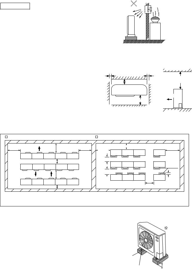
Outdoor Unit
AVOID:
●heat sources, exhaust fans, etc. (Fig. 2-1)
●damp, humid or uneven locations.
DO:
●choose a place as cool as possible.
●choose a place that is well ventilated and outside air temperature does not exceed maximum 115°F
constantly.
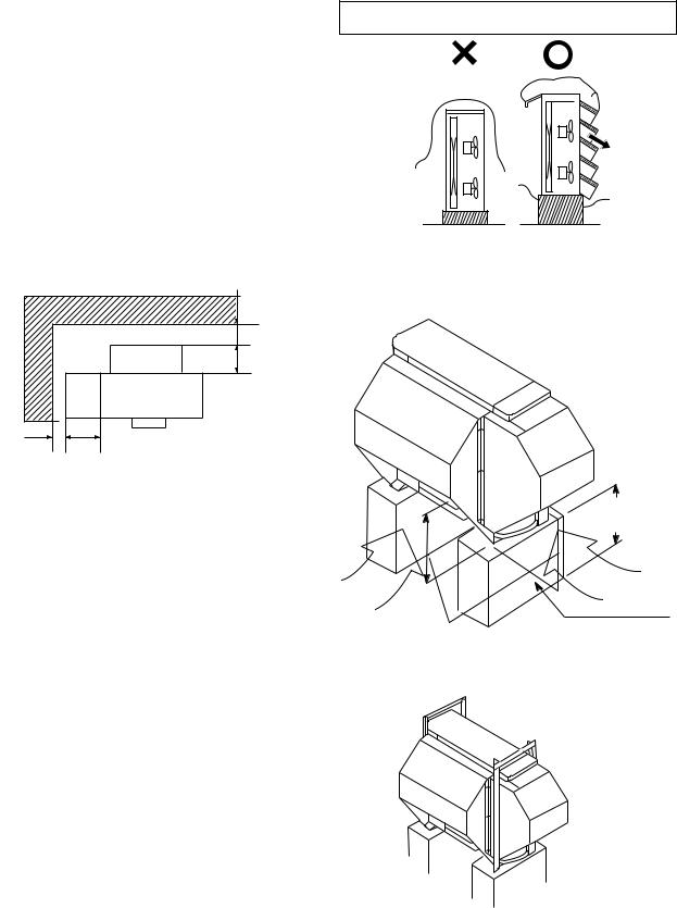
●allow enough room around the unit for air intake/ exhaust and possible maintenance. (Fig. 2-2)
●provide a solid base; about 6 inch above ground level to reduce humidity and possible water damage in the unit and decreased service life. (Fig. 2-3)
●use lug bolts or equivalent to bolt down unit, reducing vibration and noise.
In case of multiple installations
|
Exhaust fan |
|
Hot air |
|
|
|
|
Heat source |
|
Out- |
|
|
door |
|
|
unit |
|
|
|
0591_C_I |
|
Fig. 2-1 |
|
Min. |
Min. |
Obstacle above |
1 inch |
1 inch |
|
|
|
Min. |
4 in. |
|
7 ft. |
Air discharge
Min. 2 ft.
0931_C_I
Ground
0932_C_I
Fig. 2-2
|
Unit spacing if air discharge chamber is not used. |
|
Unit spacing when air discharge chamber is used. |
Min. 4 ft. |
Min. 5 ft. |
Min. 4 ft. |
Min. 4 ft. |
Min. 8 inch |
Min. 4 ft. |
|
|||||
|
Min. 1 ft. |
|
Min. 1 ft. 2 inch |
|
Air |
|
|
|
|
discharge |
|
|
|
|
|
|
|
|
|
|
|
|
chamber |
|
|
|
Min. 1 ft. 2 inch |
|
|
|
Min. 12 ft. |
|
|
|
|
|
|
|
|
|
Min. 1 ft. |
|
Min. 8 inch |
|
|
|
Min. 1 ft. |
 If you would like to make the separation smaller on the air discharge side, use an air discharge chamber.
 You can install any number of units side-by -side.
 Only up to 3 units can be installed side-by-side under the above conditions. The next group must be spaced at least 1 ft. away from the first group.
0933_C_S
Air in 
Air in
Air discharge
Concrete block
4 inch × 1 ft. 4 inch beams or equal
Min. 6 inch
Anchor bolts (4 pieces)
0934_C_I
Fig. 2-3
11 S4359146
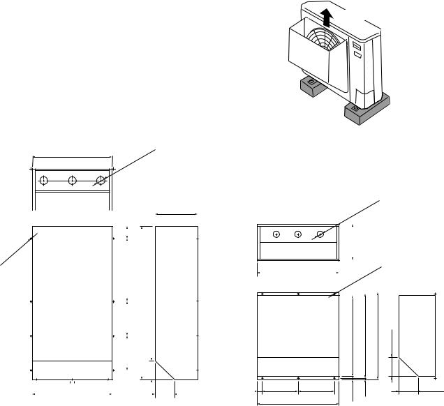
2-1. Air Discharge Chamber for Top Discharge
Air discharge
Install the air-discharge chamber in the field when: ● it is difficult to keep a space of minimum 2 ft.
between the air-discharge outlet and the obstacle.
● the air-discharge outlet is facing the sidewalk and discharge hot air can annoy the passers-by.
Refer to Fig. 2-4.
0426_C_I
22-5/16"
-3/8" |
hole |
|
|
ø2 |
|
- |
|
3 |
|
Recommended outer dimensions of wind shield (field supply)
-ø1/4" |
hole |
|
|
8 |
|
|
|
|
|
|
|
|
|
15/16"-3 |
|
11-13/16" |
|
|||||||
|
|
|
|
|
|
|
|
|
|
|
|
|
|
|||||
|
|
|
|
|
|
|
|
|
|
|
|
|
||||||
|
|
|
|
|
|
|
|
|
|
|
|
|
|
|
|
|
|
|
|
|
|
|
|
|
|
|
|
|
|
|
|
|
|
|
|
|
|
|
|
|
|
|
|
|
|
|
|
|
|
|
|
|
|
|
|
|
|
|
|
|
|
|
|
|
|
|
|
|
|
|
|
|
|
|
|
|
|
|
|
|
|
|
|
17-3/4" |
|
|
|
|
|
|
|
|||
|
|
|
|
|
|
|
|
|
|
|
|
|
|
|
|
|
||
|
|
|
|
|
|
|
|
|
|
|
|
|
43-15/16" |
|
|
|
|
|
|
|
|
|
|
|
|
|
|
|
|
|
|
|
|
|
|
||
|
|
|
|
|
|
|
|
|
|
|
|
|
|
|
|
|
||
|
|
|
|
|
|
|
|
|
|
|
|
|
|
|
|
|
|
|
|
|
|
|
|
|
|
|
7/8" |
|
|||||||||
|
|
|
|
|
|
|
|
|
|
|
|
|
|
|
||||
|
|
|
|
|
|
|
|
9- |
|
|
|
|
|
|
|
|||
|
|
|
|
|
|
|
|
|
|
|
|
|
|
5-3/16" |
|
|
|
|
|
|
|
|
|
|
|
|
|
|
|
|
|
|
|
|
|
||
|
|
|
|
|
|
|
|
-7/8" |
|
|||||||||
|
|
|
|
|
|
|
|
9 |
|
|
|
|
|
|
|
|||
|
|
|
|
|
|
|
|
|
|
|
|
|
|
|
|
|
|
|
|
|
|
|
|
|
|
|
|
|
|
|
|
|
|
|
|
|
|
|
|
|
|
|
|
|
|
|
|
|
|
|
|
|
|
|
|
|
|
|
|
|
|
|
|
|
|
|
|
|
|
|
|
|
|
|
|
|
|
|
|
|
|
|
|
|
|
|
|
|
|
|
|
|
|
|
|
23-5/16" |
|
|
|
|
|
5-5/32" |
|||||||||||
|
|
|
|
|
|
|
|
|
|
|
|
|
|
|
|
|
|
|
|
|
|
|
-9/16" |
hole |
|
|||||||||||||||
|
|
|
|
|
|
|
|
||||||||||||||
|
|
|
|
ø1 |
|
|
|
|
|
||||||||||||
|
|
|
|
- |
|
|
|
|
|
||||||||||||
|
|
|
|
3 |
|
|
|
|
|
|
|
|
|
||||||||
|
|
|
|
|
|
|
|
|
|
|
9-27/32" |
|
|
|
|
|
|||||
|
|
|
|
|
|
|
|
|
|
|
|
|
|
|
|
||||||
|
|
|
|
|
|
|
|
|
|
|
|
|
|
|
|
||||||
|
|
|
|
|
|
|
|
|
|
|
|
|
|
|
|
||||||
|
|
|
|
|
|
|
|
|
|
|
|
||||||||||
|
|
|
|
|
|
|
|
|
|
|
|
|
|
|
|
||||||
|
|
|
|
21-13/16" |
|
|
|
|
|
hole |
|
||||||||||
|
|
|
|
|
|
|
|
|
|
|
|
|
|
|
|
||||||
|
|
|
|
|
|
|
|
|
|
|
|
|
|
|
|
||||||
|
|
|
|
|
|
|
|
|
|
|
|
|
|
|
|
||||||
|
|
|
|
|
|
|
|
|
|
|
|
|
|
|
|
|
|
||||
|
|
|
|
|
|
ø15/64" |
|
|
|
||||||||||||
|
|
|
|
|
|
|
|
||||||||||||||
|
|
|
|
- |
|
|
|
|
|
||||||||||||
|
|
|
|
6 |
|
|
|
|
|
||||||||||||
|
|
|
|
|
|
|
|
|
|
|
|
||||||||||
|
|
|
|
|
|
22-7/16" |
|
23-15/32" |
|
||||||||||||
|
|
|
|
21-5/8" |
|
5-3/16" |
|||||||||||||||
1-7/32" |
9-27/32" |
9-27/32" |
15/16" |
1/2" |
5-5/32" |
|
|
||||
|
21-13/16" |
|
|
|
|
|
0936_C_I |
|
1352_C_I |
CH3642 |
CH2442 |
Fig. 2-4
2-2. Installing the Outdoor Unit in Heavy Snow
Areas
In locations subject to strong winds, snow-proof ducting should be fitted and direct exposure to the wind should be avoided as much as possible.
The following problems may occur when the outdoor unit is not provided with a platform and snow-proof ducting.
a)The outdoor fan may not run and there may be damage to the unit
b)There may be no air flow.
c)The tubing may freeze and burst.
d)The condenser pressure may drop because of strong wind, and the indoor unit may freeze.
12 S4359146
2-3. Precautions When Installing in Heavy Snow
Areas
(1)The platform should be higher than the maximum. snow depth. (Fig. 2-5)
(2)The two anchoring feet of the outdoor unit should be attached to the platform, and the platform should be installed beneath the air-intake side of the outdoor unit.
(3)The platform foundation must be solid and the unit must be secured with anchor bolts.
(4)When installing on a roof subject to strong wind, countermeasures must be taken to prevent the unit from being overturned.
In regions with snow fall, the outdoor unit should be provided with a platform and snow-proof duct.
2-4. Dimensions of Snow / Wind-proof Ducting |
Without snow- |
Snow-proof |
proof ducting |
ducting |
|
and Refrigerant Tubing Space for Installation |
(Low platform) |
(High platform) |
|
0937_C_I |
|
|
|
|
|
|
|
Fig. 2-5 |
Fig. 2-6 |
|
|
|
Min. 4" |
|
|
|
|
Duct |
12" |
Outdoor |
|
|
|
Unit |
|
||
|
|
|
|
|
|
|
Duct |
Outdoor Unit |
|
|
|
|
|
|
|
Duct |
|
|
|
|
|
|
Duct |
Min. 4" |
12" |
Unit: inch |
|
|
|
|
|
|
1117_C_I |
|
|
Higher than the maximum snow depth
Air |
Air |
|
Intake |
||
Intake |
||
|
||
|
Platform (foundation) |
|
|
About 1/2 of the |
|
|
unit height |
|
|
0488_C_I |
|
|
Fig. 2-7 |
|
|
Example of Installation |
0490_C_I
Fig. 2-8
13 S4359146
3. |
HOW TO INSTALL THE INDOOR UNIT |
■ |
4-Way Air Discharge Semi-Concealed Type |
1 |
(XH Type) |
|
X3-1. Suspending the Indoor Unit
This unit uses a drain pump. Use a carpenter’s level to check that the unit is level.
3-2. Preparation for Suspending
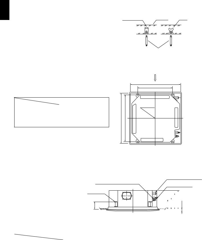
(1)Fix the suspension bolts securely in the ceiling using the method shown in the diagrams (Figs. 3-1 and 3-2), by attaching them to the ceiling support structure, or by any other method that ensures that the unit will be securely and safely suspended.
(2)Follow Fig. 3-2 and Table 3-1 to make the holes in the ceiling.
Table 3-1 |
Unit: inch (mm) |
||
Length |
A |
B |
|
Type |
|||
|
|
|
|
XH1242, XH1842 , XH2442 |
32-9/32 (820) |
22-9/32 (566) |
|
(PNR-XH2442) |
|
|
|
XH3642, XH4242 |
43-11/16 (1,110) |
33-11/16 (856) |
|
(PNR-XH3642) |
|||
|
|
||
|
|
|
|
Hole-in-anchor |
|
|
Hole-in-plug |
Concrete |
Insert |
Suspension bolt (M10 or 3/8") (field supply)
0038_T_I
Fig. 3-1
X
A (Ceiling opening)
B
(Suspention bolt pitch)
Drain hose side
opening)(Ceiling9/32-32 |
bolt(Suspention13/16pitch) |
Grille center |
|
29- |
|
Refrigerant tubing side
1969_X_S
(3)Determine the pitch of the suspension bolts using the supplied full-scale installation diagram. The diagram and table (Fig. 3-3 and Table 3-2) show the relationship between the positions of the suspension fitting, the unit, and the panel.
Refrigerant tubing joint (wide tube side)
Suspension lug
E
Fig. 3-2
Drain connection (another side) (VP25)
Refrigerant tubing joint (narrow tube side)
|
|
|
|
|
|
|
|
|
|
|
|
|
|
|
|
|
|
|
|
|
|
|
D |
|
|
|
|
|
|
|
|
|
|
C |
3/16 |
|||
|
|
|
A |
B |
|
|
||||||
|
|
|
|
|
|
|
|
|
|
|
|
1- |
|
|
|
|
|
|
|
|
|
|
|
|
|
|
|
|
|
|
|
|
|
|
|
|
|
|
1970_X_S
|
|
|
|
|
|
Fig. 3-3 |
|
Table 3-2 |
|
|
|
Unit : inch (mm) |
|||
Type |
Length |
A |
B |
C |
D |
E |
|
|
|
||||||
|
|
|
|
|
|
|
|
XH1242, XH1842, XH2442 |
6-3/16 |
7-5/32 |
10-9/32 |
12-1/8 |
4-7/8 |
|
|
|
(PNR-XH2442) |
(157) |
(182) |
(261) |
(308) |
(124) |
|
|
XH3642, XH4242 |
6-3/16 |
7-5/32 |
11-15/32 |
13-1/16 |
4-7/8 |
|
|
(PNR-XH3632) |
(157) |
(182) |
(291) |
(338) |
(124) |
|
14 S4359146
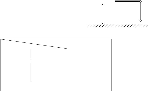
3-3. Placing the Unit Inside the Ceiling
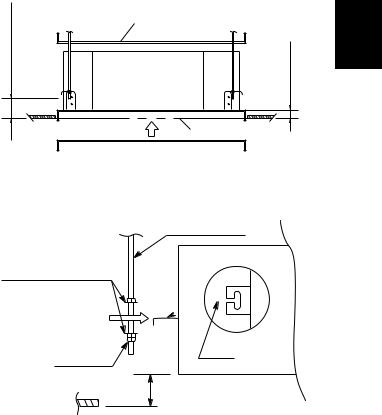
(1)When placing the unit inside the ceiling, determine the pitch of the suspension bolts using the supplied full-scale installation diagram. (Fig. 3-4) The size of the opening for the indoor unit can be confirmed by attaching the full-scale installation diagram beneath the unit. (Fig. 3-4)
Tubing and wiring must be laid inside the ceiling when suspending the unit. If the ceiling is already constructed, lay the tubing and wiring into position for connection to the unit before placing the unit inside the ceiling.
(2)The length of suspension bolt must be appropriate for a distance between the bottom of the bolt and the bottom of the ceiling of 19/32 in. or more as shown in Fig. 3-4.
(3)Thread the 2 hexagonal nuts (field supply) and washers onto the 4 suspension bolts as shown in Fig. 3-5.
Use 2 sets of nuts and washers (upper and lower), so that the unit will not fall off the suspension lugs.
(4)Remove the protective cardboard used to protect the fan parts during transport.
(5)Adjust the distance between the unit and surface of the ceiling. (1-7/8 in.) (Fig. 3-4)
inch19/32or more |
Full-scale installation diagram |
inch7/8-1 |
|
|
(printed on a cardboard packing) |
|
Full-scale installation |
|
diagram |
|
2040_X_I |
Fig. 3-4
Suspension bolt
Suspension lug
Nuts and washers (Use above and below)
Upper
Lower
Notch
Double nuts
1-7/8 inch
1971_X_I
Fig. 3-5
1
X
15 S4359146
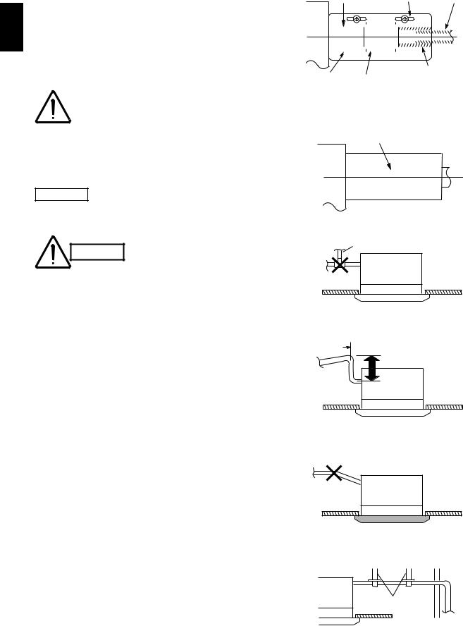
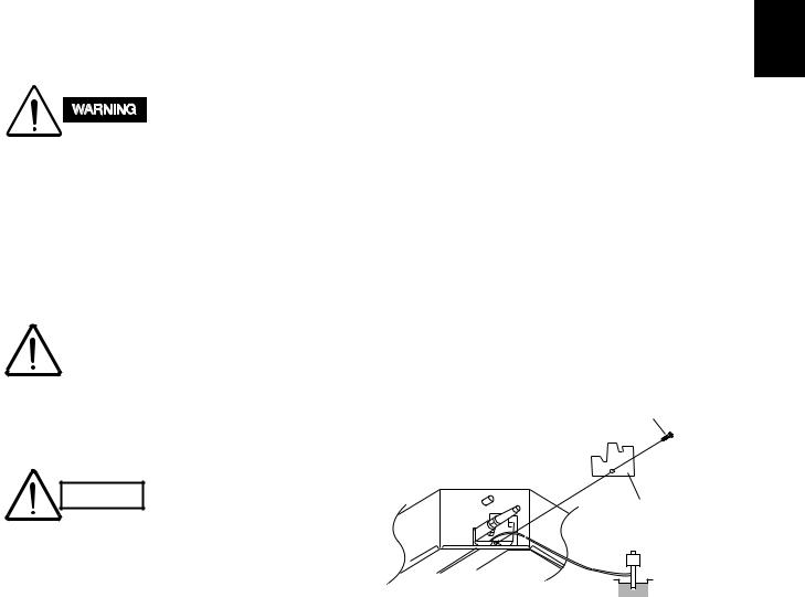
3-4. Installing the Drain Piping
(1)Prepare standard hard PVC pipe for the drain and
1 use the supplied drain hose and hose band to prevent water leaks.
XThe PVC pipe must be purchased separately.
The transparent part allows you to check drainage. (Fig. 3-6)
|
Tighten the hose clamps |
CAUTION |
so their locking nuts face |
|
upward. (Fig. 3-6) |
(2)After checking the drainage, wrap the supplied packing and drain pipe insulator around the pipe. (Fig. 3-7)
NOTE
Ensure the drain pipe has a downward gradient (1/100 or more) and that there are no water traps.
● Do not install an air
CAUTION bleeder tubes, as this may cause water to spray from the drain tube outlet. (Fig. 3-8)
●If it is necessary to increase the height of the drain pipe, the section directly after the connection port can be raised a maximum of 19-11/16 in. Do not raise it any higher than 19-11/16 in., as this could result in water leaks.
(Fig. 3-9)
●Do not install the pipe with an upward gradient from the connection port. It will cause the drain water to flow backwards and leak when the unit is stopped. (Fig. 3-10)
●Do not apply force to the piping on the unit side when connecting the drain pipe. The pipe should not be allowed to hang unsupported from its connection to the unit. Fasten the pipe to a wall, frame, or other support as close to the unit as possible. (Fig. 3-11)
●Provide insulation for any drain pipes that are installed indoors.
Transparent part for |
Hose band |
Hard PVC pipe |
|||||||||||||||||||||||
checking drainage |
(supplied) |
(not supplied) |
|||||||||||||||||||||||
|
|
|
|
|
|
|
|
|
|
|
|
|
|
|
|
|
|
|
|
|
|
|
|
|
|
|
|
|
|
|
|
|
|
|
|
|
|
|
|
|
|
|
|
|
|
|
|
|
|
|
|
|
|
|
|
|
|
|
|
|
|
|
|
|
|
|
|
|
|
|
|
|
|
|
|
|
|
|
|
|
|
|
|
|
|
|
|
|
|
|
|
|
|
|
|
|
|
|
|
|
|
|
|
|
|
|
|
|
|
|
|
|
|
|
|
|
|
|
|
|
|
|
|
|
|
|
|
|
|
Packing |
Drain hose |
Drain hose |
adapter |
||
(supplied) |
(supplied) |
(supplied) |
0964_X_I
Fig. 3-6
Drain insulator (supplied)
0197_X_I
Fig. 3-7
Air bleeder
0047_X_I
Fig. 3-8
 11-3/4 in. or less (as short as possible)
19-11/16 in. or less
1972_X_I
Fig. 3-9
Upward gradient
0049_X_I
Fig. 3-10
Support
pieces
0050_X_I
Fig. 3-11
16 S4359146
3-5. Checking the Drainage
After wiring and piping are completed, use the following procedure to check that the water will drain smoothly. For this, prepare a bucket and wiping cloth ready to catch and wipe up spilled water.
Do not supply power to the unit until the tubing and wiring to the outdoor unit are completed.
(1)Take off the tube cover and through the opening, slowly pour about 43 oz. of water into the drain pan to check drainage.
(2)Do Test Run to check the drainage after completing installation. When performing Test Run, be sure to observe the Test Run procedure.
Refer to page 89.
|
Be careful since the fan will |
|
CAUTION |
||
start turning when checking |
||
|
||
|
the drainage. |
(3)After drain checking is finished, return the Operation Selector switch to the RUN position (ON position ) and remount the tube cover.
To mount the tube cover, CAUTION use 5/16" (4 × 8 mm) tapping
screws. Do not use long screws as they may puncture the drain pan and cause water leakage.
1
X
5/16"(4 × 8 mm) tapping screw
Tube cover
Siphon
0966_X_I
Fig. 3-12
17 S4359146
1■ Ceiling Panel
X
CAUTION
Never touch or attempt to move the air direction louver by hand or you may damage the unit. Instead, use the remote control unit if you want to change the direction or air flow.
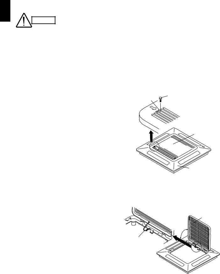
3-6. Before Installing the Ceiling Panel
(1)Remove the air-intake grille and air filter from the ceiling panel. (Figs. 3-13 and 3-14)
(a)Remove the 2 screws on the latch of the airintake grille. (Fig. 3-13)
(b)Press on the 2 latches of the air-intake grille with your thumb in the direction of the arrow to open the grille. (Fig. 3-13)
(c)With the air-intake grille open about 45˚, remove the safety string (hook on the grille side). (Fig. 3-14)
(d)Pull the air-intake grille towards you to remove it from the ceiling panel.
(2)Pull down the two panel catches on the body of the indoor unit body. (Fig. 3-15)
Screw
Latch
Air intake grille
Ceiling panel
0149_X_I
Fig. 3-13
Air filter
45°
Safety string
0150_X_I
Fig. 3-14
18 S4359146
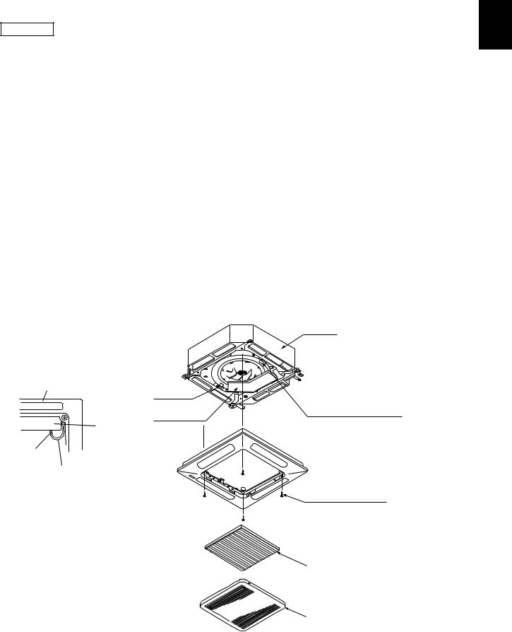
3-7. Installing the Ceiling Panel
(1)Lift the ceiling panel and position it to align the panel hook with the panel catch of the indoor unit.
NOTE
The ceiling panel must be mounted in the correct direction. Note that the 2 catches of the panel differ in size.
Confirm that the catches are correctly matched between the ceiling panel and the indoor unit body.
(2)Next, check to see that the ceiling panel is properly aligned with the seamline of the ceiling. If it is not, remove the ceiling panel and slightly readjust the indoor unit body to the proper suspension point.
(3)When the ceiling panel has been properly aligned, use the supplied 4 mounting screws (M5) with washers to permanently fasten the ceiling panel.
(4)Install the wiring connector from the ceiling panel to the connector in the electrical component box of the indoor unit. After installing the connector, use the clamp on the body of the indoor unit to secure the wiring.
(5)Install the air filter and air-intake grille by perform-
ing the steps in section 3-6 in reverse. |
1 |
|
|
||
|
|
X |
NOTE |
|
|
Rehook the safety string before closing the air-intake |
|
|
grille. |
|
|
3-8. When Removing the Ceiling Panel for |
|
|
Servicing |
|
|
When removing the ceiling panel for servicing, remove |
|
|
the air-intake grille and air filter, disconnect the wiring |
|
|
connector inside the electrical component box, and |
|
|
then remove the 4 mounting screws. |
|
|
Unit body
Ceiling panel
Panel catch
Panel catch
Electrical (arrange facing downwards)
component box
(2 locations)
Electrical component box
Clamp
Ceiling panel wiring connector
Screws M5 with washer (supplied)
Air filter
Air-intake grille
1973_X_I
Fig. 3-15
19 S4359146
3-9. Duct for Fresh Air |
For fresh air intake |
|
●There is a duct connection part on sideface of the 1 indoor unit. (Fig. 3-16)
●Optional air-intake plenum (including duct connection
X |
box and flange) can be attached to the indoor unit. |
||
|
|
|
|
|
Air-intake plenum |
Type |
|
|
|
|
|
|
CMB-GSJ80U |
PNR-XH2442 |
|
|
(XH1242, XH1842, XH2442) |
|
|
|
|
|
|
|
CMB-GSJ140U |
PNR-XH3642 |
|
|
(XH3642, XH4242) |
|
|
|
|
|
|
(1) Accessories
● Check that the following parts are in the box when unpacking.
NAME |
QT’Y |
REMARKS |
|
Cord with socket |
1 |
Connecting line. Not necessary for |
|
(9P) |
intaking fresh air. |
||
|
|||
Screw |
4 |
Air-intake filter |
|
(M5 × L5 in.) |
(for fastening) |
||
|
|||
Screw |
7 |
Duct connection flange/ box |
|
(M4 × L1/2 in.) |
(for fastening) |
||
|
|||
Duct connection box |
1 |
(for fresh air) |
|
Duct connection flange |
1 |
(for connecting fresh air duct) |
(2) Installation
● Installation steps (a) to (e) are the same for both the CMB-GSJ80U and the GSJ140U. The drawing illustrates installation of air-intake plenum to the
CMB-GSJ80U. |
Installation |
|||
|
screws |
|||
(a) Installing the air-intake plenum |
|
|
|
|
● Set the air-intake plenum to the indoor unit taking |
|
|
|
|
care not to set the incorrect direction. (Fig. 3-17) |
|
|
|
|
● Fasten the air-intake plenum with the accessory |
|
|
|
|
screws. (M5 × L5 in., 4pcs) (Fig. 3-17) |
|
|
|
|
(b) Installing the duct connection box |
|
|
|
|
● Fasten the duct connection flange to the duct |
Air-intake |
|||
connection box with the accessory screws. |
||||
plenum |
||||
(M4 × L1/2 in., 4pcs) (Fig. 3-18) |
|
|
|
|
● Put the duct connection box into the rectangular |
|
|
|
|
hole of the air-intake plenum and fasten it to the |
|
|
|
|
both sides of the indoor unit and plenum with the |
|
|
|
|
accessory screws. (M4 × L1/2 in., 3pcs) (Fig. 3-18) |
|
|
|
|
|
|
|
|
|
(c) Installing the indoor unit
● Install the indoor unit to the ceiling.
(Install the indoor unit according to items 3-1 to 3-6.)
Indoor unit
When installing in a pre- CAUTION existing location, install the
indoor unit before installing the duct connection box.
|
ø1/8 |
hole |
|
|
|
||
- |
|
|
|
4 |
|
|
|
2-3/8 |
|
|
|
ø4 |
|
|
|
|
- |
|
|
|
|
13/32 |
|
2-5/32
Detail of fresh air intake
1974_X_S
Fig. 3-16
Socket cover Panel lead wire (8P)
Clamper
8P socket (red) (electrical component box)
8P socket (red) (ceiling panel side)
1975_X_S
Fig. 3-17
20 S4359146
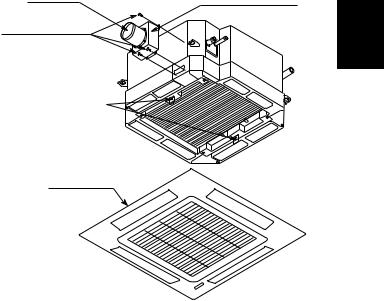
(e) Installing the ceiling panel
●Attach the ceiling panel to the chamber. Drawing the panel downwards sets the panel in position temporarily with the panel catch (at 2 locations).
●Remove the socket cover of the air-intake plenum and pass the 8P sockets through it. (Fix the panel lead wire to chamber side clamper.) (Fig. 3-17)
●Connect the 8P socket (electrical component box side) to the 8P socket (ceiling panel side) of the indoor unit electrical component box.
●Reattach the socket cover.
Duct |
|
connection |
|
flange |
Duct connection box |
|
|
Installation screws |
1 |
(M4 × 1/2 in.) |
X
Panel catch
Ceiling panel
1976_X_S
Fig. 3-18
21 S4359146
■ Wall-Mounted Type (KH Type)
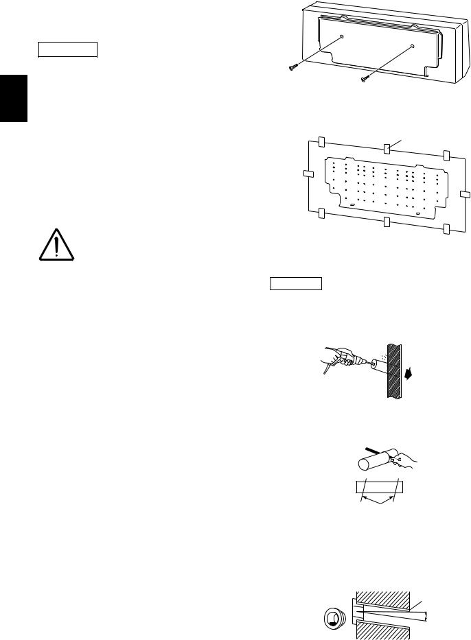
3-10. Removing the Wall Fixture from the Unit
KH2442
Remove and discard the set screws and take off the 2 wall fixture. (Fig. 3-19)
K |
3-11. Selecting and Making a Hole |
|||
|
|
|
|
|
|
|
|
|
|
|
KH2442 |
|
|
|
|
(1) Tape the full-scale installation diagram on the |
|||
|
wall at the location selected. Make sure the unit is |
|||
|
horizontal, using a level or tape measure to |
|||
|
measure down from the ceiling. (Fig. 3-20) |
|||
|
(2) Before drilling a hole, check that there are no |
|||
|
studs or pipes behind the determined location. |
|||
|
|
|
|
Avoid area where electrical |
|
|
CAUTION |
wiring or conduit is located. |
|
|
|
|
|
Also take this precaution if |
|
|
|
|
the tubing goes through a |
|
|
|
|
wall at any other location. |
(3) Using a sabre saw, key hole saw or 3-5/32 in. hole-cutting drill attachment, make a hole in the wall. The required minimum hole diameter for these models is 3-3/16 in. (Fig. 3-21)
(4) Measure the thickness of the wall from the inside edge to the outside edge and cut PVC pipe at a slight angle 1/4 in. shorter than the thickness of the wall. (Fig. 3-22)
(5) Place the plastic cover over the end of the pipe, (for indoor side only) and insert in the wall. (Fig. 3-23)
Wall fixture
Set screws only for transportation
1390_T_I
Fig. 3-19
|
Tape |
Full- |
|
scale |
installation |
|
diagram |
0940_T_I
Fig. 3-20
NOTE
Hole should be made at a slight downward slant to the outdoor side.
Indoor |
Outdoor |
side |
side |
0066_T_I
Fig. 3-21
PVC pipe (locally purchased)
Cut at slight angle
0941_T_I
Fig. 3-22
INSIDE |
Wall |
OUTSIDE |
|
|
|
Plastic |
|
PVC pipe |
cover |
|
|
|
|
Slight |
|
|
angle |
|
|
0942_K_I |
Fig. 3-23
22 S4359146
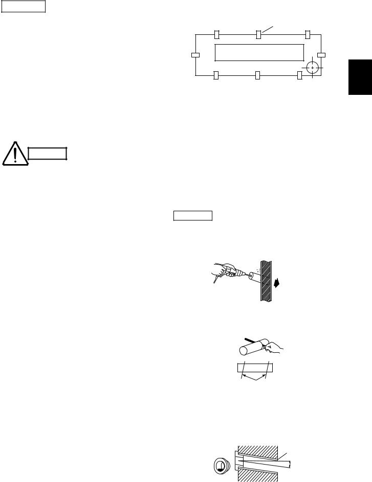
KH3642
One hole is required for the air conditioner tubing, and may be either on the left or right side. (Also see section 3-14. Preparing the Indoor Side Tubing.)
(1)Tape the full-scale installation diagram on the wall at the location selected. Make sure the unit is horizontal, using a level or tape measure to measure down from the ceiling. (Fig. 3-24)
(2)Determine if the hole is to be drilled at the left or right hole location.
(3)Before drilling a hole, check that there are no studs or pipes behind the determined location.
Tape
Full scale installation diagram
2
1354_T_I |
K |
|
Fig. 3-24
Avoid area where electrical CAUTION wiring or conduit is located.
Also take this precaution if the tubing goes through a wall at any other location.
(4)Using a sabre saw, key hole saw or 3-5/32 in. hole-cutting drill attachment, make a hole in the wall. The required minimum hole diameter for these models is 3-3/16 in. (Fig. 3-25)
(5)Measure the thickness of the wall from the inside edge to the outside edge and cut PVC pipe at a slight angle 1/4 in. shorter than the thickness of the wall. (Fig. 3-26)
(6)Place the plastic cover over the end of the pipe, (for indoor side only) and insert in the wall. (Fig. 3-27)
NOTE
Hole should be made at a slight downward slant to the outdoor side.
Indoor |
Outdoor |
side |
side |
0066_T_I
Fig. 3-25
PVC pipe (locally purchased)
Cut at slight angle
0941_T_I
Fig. 3-26
INSIDE |
Wall |
OUTSIDE |
|
|
|
Plastic |
|
PVC pipe |
cover |
|
|
|
|
Slight |
|
|
angle |
|
|
0942_K_I |
Fig. 3-27
23 S4359146
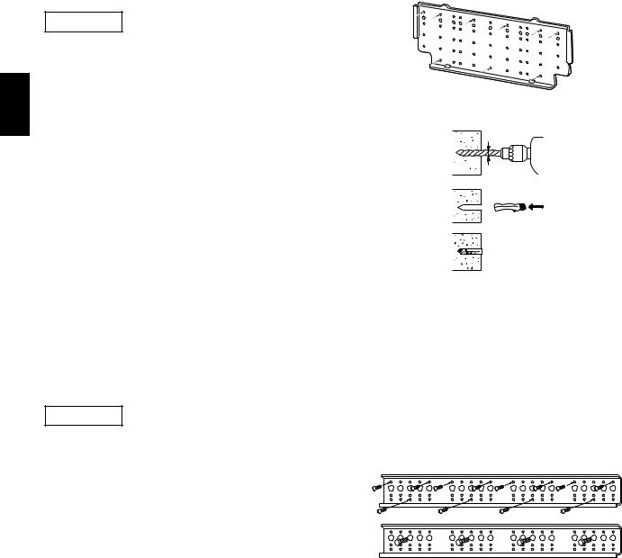
3-12. Installing the Wall Fixture onto Wooden or Gypsum Wall
KH2442
Confirm that the wall is strong enough to support the unit.
a) If the Wall is Wooden
2(1) Attach the wall fixture to the wall with the 9 screws provided. (Fig. 3-28)
KIf you are not able to line up the holes in the wall fixture with the beam locations marked on the wall, use rawl plugs or toggle bolts to go through the holes on the panel or drill 13/64 in. dia. holes in the panel over the stud locations and then mount the wall fixture.
(2)Check with a tape measure or carpenter’s level. This is important so that the unit is correctly installed.
(3)Make sure the wall fixture is flush against the wall. Any space between the wall and unit will cause noise and vibration.
b) If the Wall is Brick, Concrete or Similar
Drill 3/16 in. dia. holes in the wall. Insert rawl plugs for appropriate mounting screws. (Fig. 3-29)
KH3642
Confirm that the wall is strong enough to support the unit.
a) If the Wall is Wooden
(1)Attach the wall fixture to the wall with the 12 screws provided. (Fig. 3-30) If you are not able to line up the holes in the wall fixture with the beam locations marked on the wall, use rawl plugs or toggle bolts to go through the holes on the panel or drill 3/16 in. dia. holes in the wall fixture over the stud locations.
(2)Check with a tape measure or carpenter’s level that the wall fixture is level. This is important so that the unit is correctly installed.
(3)Make sure the wall fixture is flush against the wall. Any space between the wall and unit will cause noise and vibration.
b) If the Wall is Brick, Concrete or Similar
Drill 3/16 in. dia. holes in the wall. Insert rawl plugs for appropriate mounting screws. (Fig. 3-29)
wall fixture
0943_T_I
Fig. 3-28
3/16 in. dia. hole
Rawl plug
0944_T_I
Fig. 3-29
Wall fixture
1355_M_I
Fig. 3-30
24 S4359146
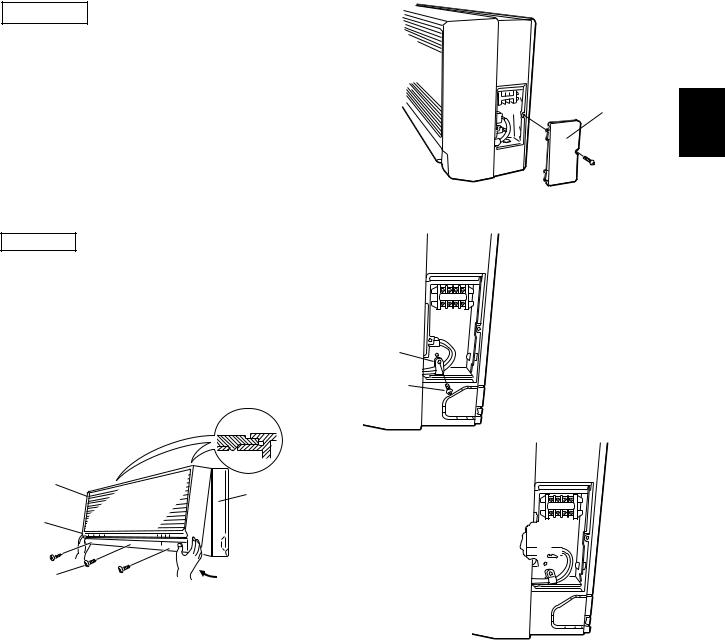
3-13. Removing the Casing to Install the Indoor Unit
KH2442
How to Remove the Casing
(1)Remove the plastic cover. (Fig. 3-31)
(2)Remove the clamp for the wiring connector. (Fig. 3-32)
(3)Disconnect the wiring connector. (Fig. 3-33)
(4)Set the flap in the horizontal position. (Fig. 3-34)
(5)Remove the 3 screws. (Fig. 3-34)
(6)Remove the casing. (Fig. 3-34)
NOTE
When replacing the casing, be careful not to crush the lead wires between the casing and the frame. (Fig. 3-34)
Casing
Frame
Flap
Screws
0947_T_I
Fig. 3-34
Plastic cover
Screw
0945_T_I
Fig. 3-31
Clamp |
|
Screw |
Fig. 3-32 |
|
2023_T_I |
Wiring 

 connector
Fig. 3-33
2024_T_I
2
K
25 S4359146
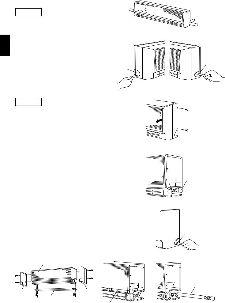
3-14. Preparing the Indoor Side Tubing |
Left |
|
tubing |
KH2442 |
Left-rear |
tubing |
Tubing can be extended in 4 directions as shown in
Fig. 3-35.
Arrangement for Left Tubing
2(a) Cut out the left tubing outlet. (Fig. 3-36)
KArrangement for Right Tubing
(a)Cut out the right tubing outlet using a hacksaw. (Fig. 3-37)
Left tubing
Arrangement for Left-rear and Right-rear Tubing. outlet
(a)It is not necessary to cut a hole.
Fig. 3-35
Fig. 3-36 |
0950_T_I |
Right-rear tubing (Recommended)
Right tubing
0949_T_I
Right tubing outlet
0951_T_I
Fig. 3-37
KH3642
Tubing can be extended in 4 directions as shown in Fig. 3-35.
Arrangement for Right-rear Tubing
(a)Remove the 2 screws and slide out the side cover. (Fig. 3-38)
(b)Extend the wide tube from the outdoor side and connect it directly to the mating tube inside the indoor unit. Use a flare nut. (Fig. 3-39)
Arrangement for Right Tubing
(a)Remove the 2 screws and take off the side cover. (Fig. 3-38)
(b)Cut out the L-shaped tubing outlet using a hacksaw. (Fig. 3-40)
(c)Using the L-shaped tube (field supply), connect tubing between the indoor and outdoor units. (Fig. 3-42)
Arrangement for Left and Left-rear Tubing.
(a)Remove the 4 screws (2 on each side) and take off both left and right side cover. (Fig. 3-41)
(b)Remove 4 screws to remove the bottom cover.
(c)Using the L-shaped tube (field supply), connect tubing as in Fig. 3-43.
Indoor unit
Left |
|
Right |
|
side |
|
||
Bottom |
side |
||
cover |
|||
cover |
|||
cover |
|||
|
|||
|
|
1361_T_I L-shaped tube
1356_T_I
Fig. 3-38
Tubing from the outdoor unit
1357_T_I
Fig. 3-39
Hack saw
Fig. 3-40 |
1358_T_I |
L-shaped tube
1359_T_I
1360_T_I
Fig. 3-41 |
Fig. 3-42 |
Fig. 3-43 |
26 S4359146

3-15. |
Wiring Instructions |
|
|
General Precautions on Wiring |
|
||
(1) |
Before wiring, confirm the rated voltage of the |
|
|
unit as shown on its name plate, then carry out |
|
||
the wiring closely following the wiring diagram. |
|
||
(2) |
Provide a power outlet to be used exclusively for |
|
|
2 |
|||
each unit a power supply disconnect and circuit |
|||
breaker for overcurrent protection should be |
K |
||
provided in the exclusive line. |
|||
|
|||
(3) |
To prevent possible hazards from insulation |
|
|
failure, the unit must be grounded. |
|
||
(4) |
All wiring must be connected tightly. |
|
|
(5) |
Do not allow wiring to touch refrigerant tubing, |
|
|
compressor, or any moving parts of the fan.
Unauthorized changes in the internal wiring can be very dangerous. The manufacturer will accept no responsibility for any damage or misoperation that occurs as a result of such unauthorized changes.
27 S4359146
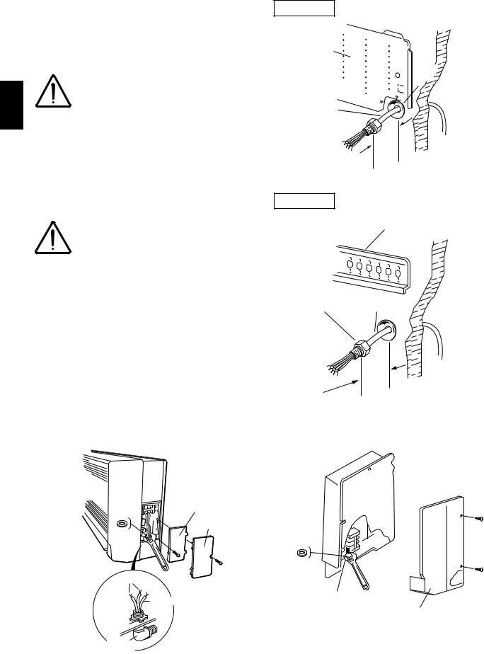
3-16. Wiring Instructions for Inter-Unit Connections
(a)Insert the inter-unit wiring (according to local codes) into the through-the-wall PVC pipe. Run the wiring toward the indoor side allowing approx. 5". to extend from the wall face. (Fig. 3-44)
|
|
Never fix the wiring by any |
2 |
CAUTION |
means before the indoor |
|
unit is fully seated on the |
|
|
||
|
|
|
K |
|
rear panel. |
(b)Remove the side cover and the metallic cover. (Fig. 3-45 or 3-46, depending on model.)
(c)Secure the conduit connector to the chassis with a lock nut. (Fig. 3-45 or 3-46)
(d)Give some play to the inter-unit wiring from the outdoor unit to the corresponding terminals on the terminal plate.
●Be sure to refer to the
CAUTION |
wiring system diagram |
|
label inside the metallic |
|
|
|
cover and carry out the |
|
correct field wiring. |
|
Wrong wiring can cause |
|
the unit to malfunction. |
|
● Check local electrical |
|
codes and any specified |
|
wiring instructions or |
|
limitations. |
(e)Secure the metallic cover with its screw. Then replace the side cover.
KH2442
Rear |
Wall |
panel |
|
Plastic cover
Wiring
5"
1362_T_I
KH3642
Wall fixture
Wall
Connector Wiring
5"
Fig. 3-44 |
1363_T_I |
|
KH2442 |
|
KH3642 |
Lock |
Metallic cover |
Metallic cover |
nut |
|
|
|
Plastic cover |
|
Screw
Lock
nut
Power line
Grounding |
Connector |
|
|
line |
Side cover |
|
Look nut |
1395_T_I |
|
|
||
Elbow |
Fig. 3-46 |
|
conduit |
||
|
0968_T_I
Fig. 3-45
28 S4359146
 Loading...