


OWNER’S MANUAL
PACKAGED TERMINAL AIR CONDITIONER Cool / Heat Model
STW-2 Series
Operating Instructions
Contents |
|
|
Page |
Alert Symbols ........................................................... |
1 |
Installation Location ................................................ |
2 |
Electrical Requirements .......................................... |
2 |
Safety Instructions ................................................... |
2 |
Names of Parts ......................................................... |
2 |
Control Panel and Operation Functions ................ |
2 |
Front Grille ................................................................ |
3 |
Other Features.......................................................... |
3 |
Care and Cleaning.................................................... |
4 |
Tips for Energy Saving ............................................ |
5 |
Troubleshooting ....................................................... |
5 |
Installation Instructions
|
Contents |
|
|
|
Page |
IMPORTANT! |
|
|
Please Read Before Starting ................................... |
6 |
|
1. |
NAMES OF PARTS............................................. |
7 |
2. |
WALL CASE AND REAR GRILLE ..................... |
7 |
3. |
INSTALLATION................................................... |
7 |
4. |
PERMANENT CONNECTION............................. |
8 |
|
4-1. For 230/208V Units ...................................... |
8 |
|
4-1-1. Preparation ........................................ |
8 |
|
4-1-2. Installation.......................................... |
8 |
|
4-2. For 265V Units ............................................. |
8 |
|
4-2-1. Preparation ........................................ |
8 |
|
4-2-2. Installation.......................................... |
8 |
5. |
AIR LOUVERS .................................................... |
9 |
6. |
TEMPERATURE LIMITING................................. |
9 |
7. |
REMOTE CONTROL ........................................ |
10 |
8. |
FRONT DESK CONTROL ................................ |
10 |
|
PRODUCT INFORMATION ............................... |
11 |
85164119653000 © SANYO 2001 |
|
|
Model No.
STW-2 Series
Power Source:
60 Hz, single-phase, 230/208V & 265V
Alert Symbols
The following symbols used in this manual alert you to potentially dangerous conditions to users, service personnel or the appliance:
WARNING
CAUTION
This symbol refers to a hazard or unsafe practice which can result in severe personal injury or death.
This symbol refers to a hazard or unsafe practice which can result in personal injury or product or property damage.
SANYO Electric Co., Ltd.
Osaka, Japan |
W |
|
W
OPERATING INSTRUCTIONS
Installation Location
•We recommend that this air conditioner be installed properly by qualified installation technicians in accordance with the Installation Instructions provided with the unit.
•Before installation, check that the voltage of the electric supply in your home or office is the same as the voltage shown on the nameplate.
WARNING |
|
• Do not install this air conditioner |
|
|
where there are fumes or flam- |
|
|
mable gases, or in an extremely |
|
|
humid space such as a green- |
|
|
house. |
|
|
• Do not install the air conditioner |
|
|
where excessively high heat- |
|
|
generating devices are placed. |
|
|
|
Electrical Requirements
1.All wiring must conform to the local electrical codes. Consult your dealer or a qualified electrician for details.
2.Each unit must be properly grounded with a ground (or earth) wire or through the supply wiring.
3.Wiring must be done by a qualified electrician.
4.Never use an extention cord with this air conditioner.
Safety Instructions
•Read this Instruction Manual carefully before using this air conditioner. If you still have any difficulties or problems, consult your dealer for help.
•This air conditioner is designed to give you comfortable room conditions. Use this only for its intended purpose as described in this Instruction Manual.
•Avoid letting cooled/heated air blow directly on your body for a long time.
WARNING |
|
• Never use or store gasoline or |
|
|
other flammable vapor or liquid |
|
|
near the air conditioner — it is |
|
|
very dangerous. |
|
|
|
CAUTION • Do not turn the air conditioner on and off from the power mains switch. Use the mode selector switch.
•Do not stick anything into the air outlet of the unit. This is dangerous because the fan is rotating at high speed.
•Do not let children play with the air conditioner.
•Do not cool or heat the room too much if babies or invalids are present.
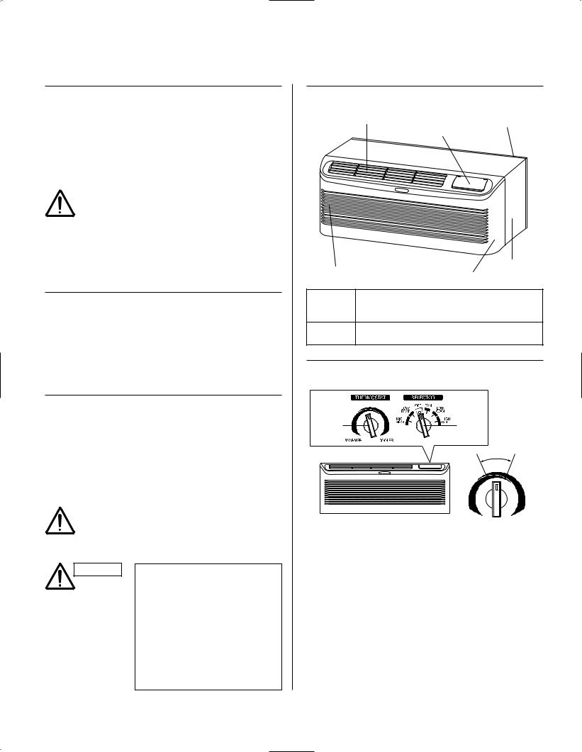
Names of Parts
Air outlet |
Cover switch and |
Rear grille |
|
control panel |
|
Wall case
Air intake
Front grille
Air Intake Air from the room is drawn into this section and passes through air filters which remove dust.
Air Outlet Conditioned air is blown out of the air conditioner through the air outlet.
Control Panel and Operation Functions
Thermostat |
Mode |
|
selector |
rmedi |
|
Inte |
ate |
range |
|
7 |
2°F |
(88° F) |
(55° F) |
WARMER COOLER
Thermostat Control
The thermostat knob is used to control the room temperature. The unit automatically cycles on and off to maintain room temperature. A comfortable temperature will be maintained in most rooms when the control is set to about intermediate range.
Mode Selector
HI HEAT provides heating with high fan speed operation. LOW HEAT provides heating with low fan speed operation. OFF setting stops heating or cooling operation.
FAN provides fan operation without cooling or heating. LO COOL provides cooling with low fan speed operation. HI COOL provides cooling with high fan speed operation.
As long as power is connected to the unit, Freeze Protection always functions at any position even at OFF position.
2

Operation:
1.Set the mode selector for fan, cooling or heating operation.
2.Set the thermostat to the desired position. (Refer to the Setting Temperature Guide on page 2.)
NOTE
The temperatures at the Setting Temperature Guide on Page 2 are provided for reference only, and may differ from the actual temperature of the room.
How to stop the air conditioner:
Set the mode selector to OFF position.
How to restart the air conditioner:
Set the mode selector to the desired position.
Front Grille
To remove:
Additional controls are located behind the front grille. Pull out to release it from the tabs. Then lift up.
2 
Front grille
1
To reinstall:
Place the tabs over the top rail. Push inward until it snaps into place.
1
2
Air Louvers
To change the louver direction, remove the front grille and 2 louver screws that hold the louvers in place. Turn the louver section 180° (end for end), replace the screws and replace the front grille. The textured face of the louver section must be facing toward the room side.
Front grille
Louver screws
The direction of the heated or cooled air may be adjusted by removing and turning the louvers around.
37° OFF VERTICAL |
20° OFF VERTICAL |
Other Features
Ventilation Control
The ventilation control lever is located at the upper left side of the unit, behind the front grille.
This knob is set to CLOSE at the factory. When in this position, the vent door is closed and only indoor air is circulated by the air conditioner. Switching the knob to OPEN opens the vent door to allow outdoor air to enter the room. However, leaving the vent door at OPEN reduces heating or cooling effectiveness and increases operating costs.
Ventilation control lever
Remote Control
Remote controlling is available with the optional Class 2 Remote Controller and Interface kit. See the Installation Instructions.
3
Fan Cycle Switch
The Fan Cycle Switch is located under the control panel behind the front grille. This switch is set to CONT at the factory to provide continuous fan operation in cool or heat modes. Leaving the switch at the CONT setting allows continuous circulation of room air and will keep the room temperature at stable condition. If you want the fan to cycle on and off with the compressor or electrical heater, set the switch to CYCLE.
|
THERMOSTAT |
SELECTOR |
|
|
|
||
|
LOW |
OFF FAN |
LOW |
|
HEAT |
|
|
|
HIGH |
|
COOL |
|
HEAT |
|
HIGH |
|
|
|
COOL |
WARMER |
COOLER |
|
|
|
|
|
|
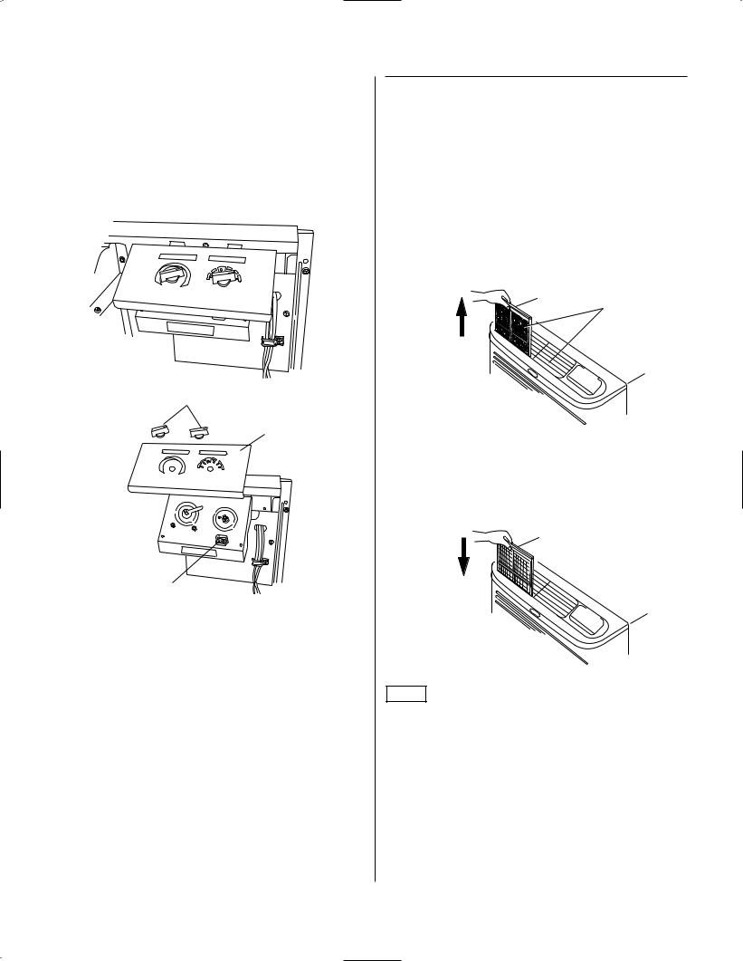
Care and Cleaning
Turn off the air conditioner before cleaning.
Air Filters
The air filters should be cleaned at least once every two weeks. Clogged filters reduce cooling, heating and air flow.
Keeping these filters clean will:
•Decrease cost of operation.
•Save energy.
•Prevent clogged heat exchanger coils.
•Reduce costly compressor problems.
To remove the air filters:
Pull up |
2 air filters |
Knob
Control panel
|
THERMOSTAT |
SELECTOR |
|
|
LOW |
OFF |
FAN |
|
|
LOW |
|
|
HEAT |
|
COOL |
|
HIGH |
|
HIGH |
|
HEAT |
|
COOL |
WARMER |
COOLER |
|
|
CYCLE |
CONT |
|
Fan cycle switch
Freeze Protection
Freeze Protection helps prevent plumbing damage due to sub-freezing temperatures — even if you have turned the mode selector switch to OFF. The unit automatically turns on the heater and fan if the room temperature falls to about 46°F.
You do not have to do anything to activate the Freeze Protection. It will work as long as power to the unit has not been interrupted.
Front
To clean the air filters:
•Vacuum off heavy dirt.
•Run water through the filters.
•Dry thoroughly before replacing.
To reinstall the air filters:
Push down
NOTE
Do not operate the air conditioner without the filters in place. If a filter becomes torn or damaged it should be replaced immediately. Operating the unit without the filters in place or with damaged filters will allow dirt and dust to reach the indoor coil and reduce the efficiency of the unit.
Replacement filters (STK01AF) are available from the dealer or installer.
Front Grille & Wall Case
Wash the front grille and wall case finish with mild soap or detergent and lukewarm water.
4
 Loading...