


INSTRUCTION MANUAL
CO2 Incubator
MCO-19AIC UV
MCO-19AIC
91
CONTENTS
INTRODUCTION |
|
|
|
|
|
|
2 |
PRECAUTIONS FOR SAFE OPERATION |
3 |
||||||
LABELS ON THE INCUBATORS |
|
|
|
|
|
|
7 |
ENVIRONMENTAL CONDITIONS |
|
|
|
7 |
|||
INCUBATOR COMPONENTS |
|
|
|
|
|
|
8 |
Control panel and keypad |
|
|
|
|
|
|
10 |
Remote alarm terminals |
|
|
|
|
|
|
11 |
INSTALLATION SITE |
|
|
|
|
|
|
12 |
INSTALLATION |
|
|
|
|
|
|
13 |
Connection of CO2 gas cylinder |
|
|
|
14 |
|||
PREVENTING CONTAMINATION |
|
|
|
15 |
|||
PRECAUTIONS FOR CULTURES |
|
|
|
16 |
|||
Using the unlock key |
|
|
|
|
|
|
17 |
CORRECT OPERATION |
|
|
|
|
|
|
17 |
LCD PANEL |
|
|
|
|
|
|
18 |
BASIC OPERATIONS ON CONTROL PANEL |
19 |
||||||
BASIC PARAMETERS |
|
|
|
|
|
|
20 |
Setting the chamber temperature and CO2 density |
20 |
||||||
Setting the key lock |
|
|
|
|
|
|
21 |
Removing the key lock |
|
|
|
|
|
|
21 |
Setting the key lock password |
|
|
|
|
|
|
22 |
Setting the upper limit alarm temperature |
24 |
||||||
ALARM PARAMETERS |
|
25 |
|||||
UV LAMP PARAMETERS |
|
|
|
|
|
|
26 |
Using the UV lamp |
|
|
|
|
|
|
26 |
Precautions when using the UV lamp |
|
|
|
27 |
|||
Setting the UV lamp ON period |
|
|
|
28 |
|||
Lighting the UV lamp for 24 hours |
|
|
|
29 |
|||
OTHER PARAMETERS |
|
|
|
|
|
|
30 |
Setting the date, time, and log interval |
|
|
|
30 |
|||
Initial settings (LCD/DAQ parameters) |
|
|
|
32 |
|||
DISPLAYING THE LOG |
|
|
|
|
|
|
33 |
Transferring data |
|
|
|
|
|
|
34 |
WATER LEVEL SENSOR |
|
|
|
|
|
|
35 |
ROUTINE MAINTENANCE |
|
|
|
|
|
|
|
Cleaning the chamber and inner attachments |
36 |
||||||
Filling the humidifying pan |
|
|
|
|
|
|
39 |
H2O2 DECONTAMINATION |
|
|
|
|
|
|
40 |
H2O2 decontamination |
|
|
|
|
|
|
42 |
Precautions when handling H2O2 decontamination reagent |
45 |
||||||
ALARMS, SAFETY, AND SELF-DIAGNOSIS |
46 |
||||||
CALIBRATION |
|
|
|
|
|
|
|
Temperature/CO2 calibration |
|
|
|
|
|
|
48 |
TROUBLESHOOTING |
|
|
|
|
|
|
50 |
DISPOSING OF THE CO2 INCUBATOR |
|
|
|
52 |
|||
AUTOMATIC CO2 CYLINDER CHANGEOVER |
57 |
||||||
AUTOMATIC CO2 DENSITY CALIBRATION |
59 |
||||||
STACKING INCUBATORS |
|
|
|
|
|
|
62 |
SPECIFICATIONS |
|
|
|
|
|
|
64 |
PERFORMANCE |
|
|
|
|
|
|
65 |
SAFETY CHECK SHEET |
|
|
|
|
|
|
66 |
1 |
|
|
|
92 |
|
|
|
|
|
|
|
|
|
||

INTRODUCTION
ŶRead this manual carefully before using the Product and follow the instructions for safety operation.
ŶSanyo disavows any responsibility for safety if the Product is used for other than the intended use or used with any procedures other than those given in this manual.
ŶKeep this manual in a suitable place so that it can be referred to as necessary.
ŶThe contents of this manual are subject to change without notice for improvement of performance or functions.
ŶContact a Sanyo sales representative or agent if any page of the manual is lost or the page order is incorrect.
ŶContact a Sanyo sales representative or agent if any point in this manual is unclear or if there are any inaccuracies.
ŶNo part of this manual may be reproduced in any form without the expressed written permission of Sanyo.
93 |
|
2 |
|

PRECAUTIONS FOR SAFE OPERATION
It is imperative that the user complies with this manual as it contains important safety advice.
Items and procedures are described so that you can use this unit correctly and safely. If the precautions advised are followed, this will prevent possible injury to the user and any other person.
Precautions are illustrated in the following way:
 WARNING
Failure to observe WARNING signs could result in a hazard to personnel possibly resulting in serious injury or death.
 CAUTION
Failure to observe CAUTION signs could result in injury to personnel and damage to the unit and associated property.
Symbol shows;
this symbol means caution.
this symbol means an action is prohibited.
this symbol means an instruction must be followed.
Be sure to keep this manual in a place accessible to users of this unit.
< Label on the unit >
This mark is labeled on the cover in which the electrical components of high voltage are enclosed to prevent the electric shock.
The cover should be removed by a qualified engineer or a service personnel only.
 WARNING
As with any equipment that uses CO2 gas, there is a likelihood of oxygen depletion in the vicinity of the equipment. It is important that you assess the work site to ensure there is suitable and sufficient ventilation. If restricted ventilation is suspected, then other methods of ensuring a safe environment must be considered. These may include atmosphere monitoring and warning devices.
3 |
|
94 |
|
 WARNING
Do not use the unit outdoors. Current leakage or electric shock may result if the unit is exposed to
rain water.
Only qualified engineers or service personnel should install the unit. The installation by
unqualified personnel may cause electric shock or fire.
Install the unit on a sturdy floor and take an adequate precaution to prevent the unit from  turning over. If the floor is not strong enough or the installation site is not adequate, this may result
in injury from the unit falling or tipping over.
Never install the unit in a humid place or a place where it is likely to be splashed by water.
Deterioration of the insulation may result which could cause current leakage or electric shock.
 Never install the unit in a flammable or volatile location. This may cause explosion or fire.
Never install the unit where acid or corrosive gases are present as current leakage or electric
shock may result due to corrosion.
Always ground (earth) the unit to prevent electric shock. If the power supply outlet is not grounded, it will be necessary to install a ground by qualified engineers.
Never ground the unit through a gas pipe, water main, telephone line or lightning rod. Such
grounding may cause electric shock in the case of an incomplete circuit.
Connect the unit to a power source as indicated on the rating label attached to the unit. Use
of any other voltage or frequency other than that on the rating label may cause fire or electric shock.
Never store volatile or flammable substances in this unit if the container cannot be sealed. These
may cause explosion or fire.
Do not insert metal objects such as a pin or a wire into any vent, gap or any outlet on the unit.
This may cause electric shock or injury by accidental contact with moving parts.
Use this unit in safe area when treating the poison, harmful or radiate articles. Improper use
may cause bad effect on your health or environment.
Turn off the power switch (if provided) and disconnect the power supply to the unit prior to any repair or maintenance of the unit in order to prevent electric shock or injury.
Do not touch any electrical parts (such as power supply plug) or operate switches with a wet hand. This may cause electric shock.
95 |
|
4 |
|
 WARNING
Ensure you do not inhale or consume medication or aerosols from around the unit at the time of maintenance. These may be harmful to your health.
 Never splash water directly onto the unit as this may cause electric shock or short circuit.
Never put containers with liquid on the unit as this may cause electric shock or short circuit when the liquid is spilled.
Never bind, process, or step on the power supply cord, or never damage or break the power supply plug. A broken supply cord or plug may cause fire or electric shock.
 Do not use the supply cord if its plug is loose. Such supply cord may cause fire or electric shock.
Never disassemble, repair, or modify the unit yourself. Any such work carried out by an unauthorized person may result in fire, or electric shock or injury due to a malfunction.
Disconnect the power supply plug if there is something wrong with the unit. Continued abnormal operation may cause electric shock or fire.
When removing the plug from the power supply outlet, grip the power supply plug, not the cord. Pulling the cord may result in electric shock or fire by short circuit.
Disconnect the power supply plug before moving the unit. Take care not to damage the power cord. A damaged cord may cause electric shock or fire.
Disconnect the power plug when the unit is not used for long periods. Keeping the connection may cause electric shock, current leakage, or fire due to the deterioration of insulation.
If the unit is to be stored unused in an unsupervised area for an extended period, ensure that children do not have access and that doors cannot be closed completely.
The disposal of the unit should be accomplished by appropriate personnel. Remove doors to prevent accidents such as suffocation.
 Do not put the packing plastic bag within reach of children as suffocation may result.
Use the reagent specified by Sanyo for H2O2 decontamination. Using a different H2O2 solution may result in explosion or damage to the Incubator.
When performing H2O2 decontamination, securely close the internal and external doors. Failure to do so may be harmful to health due to leakage of H2O2 gas.
During H2O2 decontamination, plug the access hole with the silicon cap that is provided. Failure to do so may be harmful to health due to leakage of H2O2 gas.
5 |
|
96 |
|
 CAUTION
Use a dedicated power source (a dedicated circuit with a breaker) as indicated on the rating label
attached to the unit. A branched circuit may cause fire resulting from abnormal heating.
Connect the power supply plug to the power source firmly after removing the dust on the plug.
A dusty plug or improper insertion may cause a heat or ignition.
Never store corrosive substances such as acid or alkali in this unit if the container cannot be
sealed. These may cause corrosion of inner components or electric parts.
Check the setting when starting up of operation after power failure or turning off of power switch. The stored items may be damaged due to the change of setting.
 Be careful not to tip over the unit during movement to prevent damage or injury.
Prepare a safety check sheet when you request any repair or maintenance for the safety of service
personnel.
Wear rubber gloves when handling the H2O2 reagent. Direct contact with the H2O2 reagent may result in inflammation of the skin.
H2O2 decontamination can be performed only for the chamber and chamber attachments with standard specifications, and not for any other objects.
Perform H2O2 decontamination with the chamber attachments arranged as specified by Sanyo.
Arranging them in a different way may result in insufficient decontamination.
After H2O2 decontamination has been completed, wear rubber gloves and use a non-woven cloth to wipe off the residual H2O2 fluid from the bottom of the chamber, any objects that were decontaminated, and the bottoms of ducts.
97 |
|
6 |
|
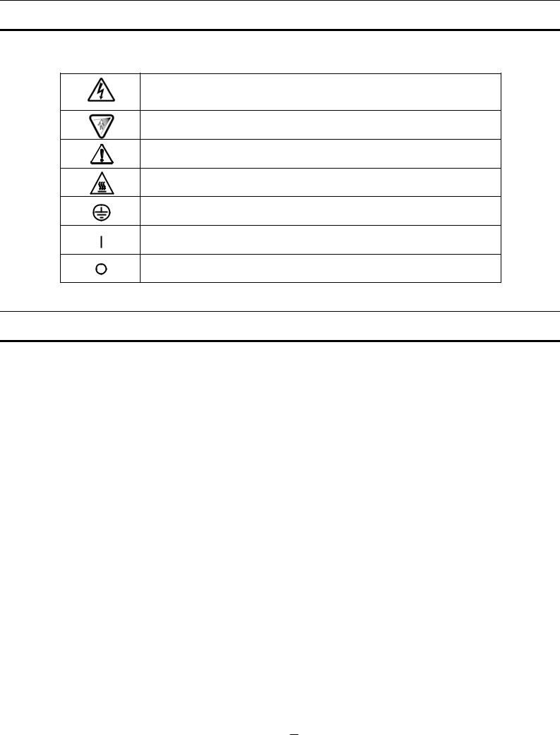
LABELS ON THE INCUBATOR
Warning and caution labels are attached to the Incubator. The following table describes the labels.
This label is attached to covers that access high-voltage electrical components to prevent electric shock. Only a qualified engineer or service personnel should be allowed to open these covers.
This symbol indicates an ultraviolet light (UV) caution.
This symbol indicates that caution is required. Refer to product documentation for
details.
This symbol indicates a hot surface.
This symbol indicates an earth.
This symbol means “ON” for a power switch.
This symbol means “OFF” for a power switch.
EMVIRONMENTAL CONDITIONS
The Indicator is designed to be safe if used under the following conditions (based on the IEC 61010-1):
ŶIndoors
ŶAltitudes up to 2000 m
ŶAmbient temperature from 5 to 40oC
ŶMaximum humidity of 80% for temperatures up to 31oC decreasing linearly to maximum humidity of 50% at 40oC
ŶMain power supply voltage fluctuations of r10% of the nominal voltage
ŶOther power supply voltage fluctuations as stated by the manufacturer
ŶTransient overvoltages according to Installation Category II
For the main power supply, the minimum and normal category is II.
Ŷ Pollution degree 2 according to IEC 60664.
7 |
|
98 |
|

INCUBATOR COMPONENTS
1 |
6 |
5 12 7 9 (inside) 8 |
2
4
15, 16 (inside)
For MCO-19AIC(UV) or
when MCO-19UVS is installed.
22 |
10 |
|
|
13 (inside) 14 |
3 |
21 |
18 |
||
|
|||
|
|
|
|
|
|
|
|
|
|
|
|
17 |
20 |
11 |
|
||
|
|
19 |
For MCO-19AIC(UV) or
when MCO-19UVS is installed.
Rear Right Side |
Rear Left Side |
99 |
|
8 |
|

1.Outer door: The outer door is held to the frame with a magnetic seal. A door heater is installed in the door panel. The door opening is reversible. Contact a Sanyo representative or agent to change the door hinge from left to right or vice versa.
2.Inner door: The inner door is made of tempered glass. However do not subject the glass to excessive impacts.
3.Leveling feet: The leveling feet can be turned to adjust the height. Adjust the feet so that the Incubator is level.
4.Trays: The trays can be pulled forward.
5.Tray supports: The tray supports can be removed by lifting the front side and pulling toward you.
6.Side supports: The right and left side supports can be removed for disinfection. Refer to page 36 and
7.Fan cover: The fan cover serves as the inlet for circulating air. It is removable.
8.Duct: The duct for the path for circulating air. It is removable.
9.Fan (inside the duct): The fan is made from polypropylene resin. It can be disinfected in an autoclave.
10.Sample air outlet: The sample air outlet also functions as an internal gas outlet. Normally, cover this outlet with the sample air outlet cap.
11.Connecting port A/B for CO2 gas pipe: When the optional MCO-21GC Automatic CO2 Cylinder Changeover System is installed, both ports A and B are available. If the MCO-21GC is not installed, only
port A is available. Refer to page 14 for gas cylinder connection. Ensure that the gas pressure is set at 0.03 MPaG (0.3 kgf/cm2G, 4.3 psiG). Refer to page 57 for automatic CO2 cylinder changeover system.
12.Door switch: The door switch detects when the door is open and stops the circulating fan and electromagnetic valve for CO2 and UV lamp.*
13.Humidifying pan: Fill the humidifying pan with sterile distilled water. Install the pan properly so that it can be covered with the pan cover.
14.Humidifying pan cover: The cover prevents UV light entering the chamber. When filling the pan, lift the front side and take out the pan. Refer to page 39 for details.
15.UV lamp*: This Sanyo UV lamp does not generate ozone. Never look directly at the UV light. For replacement, contact a Sanyo representative or agent.
16.Water level sensor for humidifying pan: This sensor detects the water level in the humidifying pan. Refer to page 35 for details.
17.Remote alarm terminals: Refer to page 11.
18.Access port: Place the silicon caps on the port both outside and inside when the port is not being used.
19.Power switch: This is the main switch for the Incubator. It also functions as an overcurrent breaker.
20.Glow starter*: The glow started if for the UV lamp (model FG-7P)
21.Attachment location for electric key: This is the attachment location for the electric key included in the optional Component H2O2 Decontamination Kit (MCO-HL). This kit must be attached to perform H2O2 decontamination. Refer to the installation procedure for MCO-HL for details.
22.Sample air outlet cap: Always attach this cap except when using the sample air outlet.
* MCO-19AIC(UV) or when an optional UV System Kit (MCO-19UVS) is installed.
9 |
|
100 |
|
Control panel and keypad
1
3
11
2
4
5
8
10
9
6 |
|
|
7 |
||
1.LCD panel
2.Upper limit regulator:
This regulator is used to set the upper temperature limit.
3. OVERHEAT indicator:
This indicator lights when the chamber temperature reaches the upper limit.
4. MENU Key:
Press this key to access the menu.
5. Contrast knob:
Turn this knob to adjust the contrast of the LCD.
6. BUZZER Key:
Press this key to silence the buzzer.
7. CE Key:
Press this key to clear the entered value when entering a setting.
8.Cursor Keys (Up, Down, Left, and Right): Use these keys to move the cursor on the LCD panel.
9.ENTER Key:
Press this key to select a menu command. When entering a setting, pressing this key to move to the next parameter.
10.Numeric Keys
11.H2O2 Key:
Press this key to start H2O2 decontamination. Refer to page 40 for details.
Note: It is not possible to silence the buzzer for an upper limit temperature alarm.
The following optional components must be installed to perform decontamination. |
|
|||||
UV Lamp Add-on Kit (MCO-19UVS) (This is provided as standard equipment for the MCO-19AIC(UV).) |
|
|||||
H2O2 |
Decontamination Kit (MCO-HL) |
|
||||
H2O2 |
Generator (MCO-HP) |
|
||||
|
|
|
101 |
|
|
10 |
|
|
|
||||
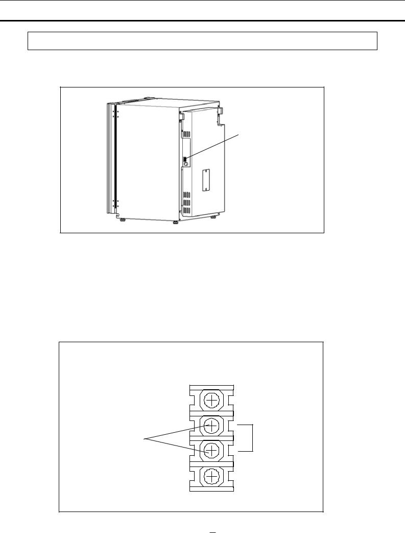
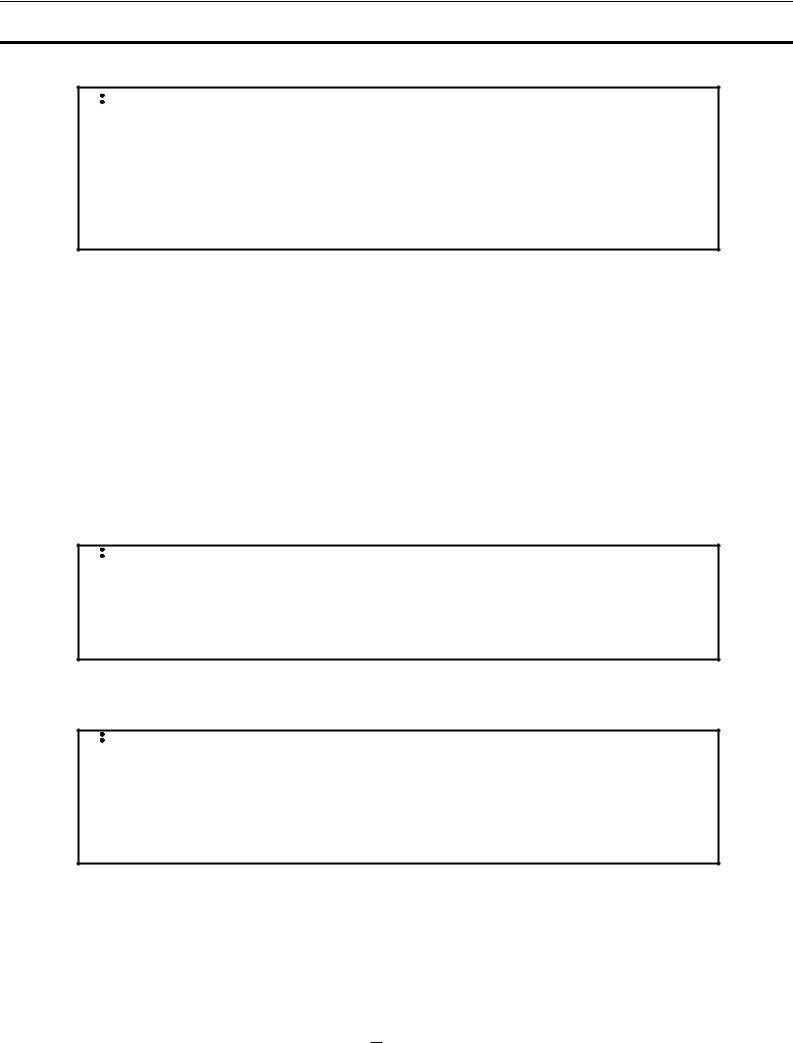
Remote alarm terminals
The remote alarm terminals are located at the rear right side.
Remote alarm
terminals
The remote alarm terminals are a contact output.
Normal: Open
Alarm: Closed
Contact capacity: 30 VDC, 2 A
Note:
•When the power switch is OFF or power is interrupted, the contact output will be closed.
•The remote alarm cannot be silenced by pressing the BUZZER Key since the remote alarm is not conjunct with the BUZZER Key.
REMOTE ALARM
MAX DC30V 2A
Remote alarm terminals |
N.O. |
11 |
|
102 |
|
INSTALLATION SITE
For correct operation of the Incubator, install it in a location with the following conditions.
 WARNING
When using CO2 gas for control, make sure that there is adequate ventilation. Using CO2 gas in a small room without adequate ventilation may cause gas poisoning or oxygen deprivation. In addition, when opening the Incubator doors, do not directly inhale the air in the chamber.
Si l’appareil est utilisé dans un evdroit restreint, le niveau de la densite CO2 de l’air peut s’élever et peut être nocif aux humains. Evitez d’aspirer l’air provenant de l’inérieur de l’appareil quand vous ouverz la porte.
z Normal air environment
Install the Incubator in an environment with normal air. z Do not expose to direct sunlight
Do not install the Incubator in a location where it will be exposed to direct sunlight. If the Incubator is operated in direct sunlight, performance will be adversely affected.
z Separate from heat sources
Do not install the Incubator near significant heat sources, such as heaters, boilers, ovens, or autoclaves. Heat will adversely affect the performance of the Incubator.
z Ambient temperature at least 5qC lower than set temperature
The control temperature of the Incubator is at least 5qC higher than the ambient temperature. For example, if the chamber is controlled at 37qC, the ambient temperature must normally be no more than 32qC. Do not allow the ambient temperature to become too high.
z Strong and level floor
Select a site with a strong and level floor. If the floor is uneven or the installation is not level, the Incubator will be unstable and this may cause accident or injury. To avoid vibration and noise, always make sure that the installation is stable. An unstable surface may result in vibration or noise.
 WARNING
Install the Incubator at a location that can support the weight. If the floor is not strong enough or if the
installation is insufficient, the Incubator may fall over and cause injury.
Always make sure that the floor is strong, even, and level, and that the Incubator will not tip over.
An insufficient installation may result in injury due to water leakage or the Incubator falling over.
z Low humidity
Select a site with a relative humidity of 80% or lower. Using the Incubator in high humidity may result in current leakage or electric shock.
 WARNING
Do not use the Incubator outdoors. If the Incubator is exposed to rain water, it may result in current
leakage or electric shock.
Never install the Incubator in a moist location, such as near a sink or water line, or where it is likely to be exposed to water. In addition, do not install it near water or steam pipes. Moisture can
cause the insulation to deteriorate, which may result in current leakage or electric shock.
z No inflammable or corrosive gas
Never install the Incubator in a location where it will be exposed to inflammable or corrosive gas. Doing so may result in explosion or fire. In addition, insulation may deteriorate due to corrosion of protective casing, resulting in current leakage or electric shock.
z No falling objects
Do not install the Incubator in a location where there is the possibility of objects falling from above. Doing so may result in damage or accident.
103 |
|
12 |
|
INSTALLATION
1. Remove the packing tape and clean up.
Remove all the tape that is securing the doors and inner attachments. Open the doors for ventilation. If the outer panels are dirty, dampen a cloth with a diluted neutral detergent and wipe them. (Using an undiluted solution may damage the plastic. Follow the diluting instructions for the detergent that is used.)
Wipe off the residual detergent with a wet cloth and then wipe off any moisture.
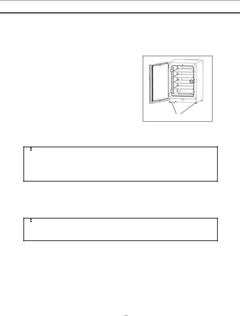
2. Adjust the leveling feet.
Adjust the leveling feet by turning them counterclockwise to level the
Incubator. (See the illustration on the right.)
3. Ground the Incubator.
Ground the Incubator during installation to prevent electric shock in case the insulation is not sufficient. If there is no ground wire at the location, consult with qualified service personnel.
Leveling feet
z When a ground must be installed
If a grounded 3-pole outlet is not available, then a ground must be installed. Consult with qualified service
personnel.
 WARNING
To prevent electric shock, always ground the Incubator. If grounding is not possible, then have a ground installed by qualified personnel. If the Incubator is not grounded, it may result in electric shock.
Never connect the ground wire to a gas pipe, water pipe, lightning rod, or telephone ground wire.
Doing so may cause electric shock.
z Installing a ground fault circuit breaker
If using the Incubator in a location with moisture or humidity cannot be avoided, then it is recommended that a ground fault circuit breaker be installed in the power supply circuit (i.e., the power supply at the Incubator). Have the circuit breaker installed by qualified service personnel.
 CAUTION
Do not climb on the Incubator or place objects on top of it. Doing so may damage it or cause it to fall over, resulting in injury. If it is to be stacked, refer to page 62 and stack it securely.
z When the Incubator is not in use
Empty the water from the humidifying pan and remove moisture from the chamber. Make sure that the chamber is completely dry before closing the doors. Failure to do so may result in damage.
z Before moving the Incubator
Before moving the Incubator, empty the water from the humidifying pan, disconnect the power supply plug from the outlet, and make sure that the cord will not be damaged. Failure to do so may result in electric shock or fire.
13 |
|
104 |
|

Connecting a CO2 gas cylinder
 WARNING
When connecting a gas cylinder to the Incubator, confirm the gas type. Confirm that the connections
are secure and that no gas will escape. Be sure to use the specified pressure. Using an incorrect
gas or pressure may result in explosion or fire, or in gas poisoning or oxygen deprivation due to escaping
gas.
Install the Incubator in a location with adequate ventilation. If adequate ventilation cannot be
provided, then install an alarm system using CO2 and O2 densitometers.
1.Use a liquefied CO2 gas cylinder (at least 99.5% pure). The siphon (dip tube) type cannot be used.
2.Install the Gas Pressure Regulator (MCO-100L, purchased separately) specified by Sanyo on the CO2
gas cylinder. Otherwise, use a CO2 gas pressure regulator rated at 25 MPaG (250 kgf/cm2G, 3600 psiG) for the primary pressure, and 0.2 MPaG (2 kgf/cm2G, 30 psiG) for the secondary pressure.
3. Using the gas supply pipe that is provided, connect the CO2 gas pressure regulator to the CO2 gas pipe inlet (located at the lower left-hand side on the rear panel of the Incubator).
Note:
If CO2 is supplied to multiple CO2 Incubators from a single gas cylinder, a CO2 solid will be formed in the gas pressure regulator. The gas pressure regulator safety valve will operate, and there may an explosive sound.
When the MCO-21GC is not mounted
Using the gas supply pipe that is provided, connect the CO2 gas pressure regulator for the CO2 gas cylinder to CO2 gas pipe connection port A on the Incubator. After connecting the pipe, check to make sure that no gas is leaking.
When the MCO-21GC is mounted
Connect a pair of CO2 gas cylinders with CO2 gas pressure regulators independently. The gas supply line will be switched automatically. Connect the main cylinder to port A and the reserve cylinder to port B. After connecting the cylinders, check to make sure that no gas is leaking.
z For details on installing the optional automatic CO2 Cylinder Changeover Kit (MCO-21GC), refer to the MCO-21GC installation guide. For details on using the MCO-21GC, refer to page 57.
4. Set the CO2 gas on the secondary side to 0.03 MPaG (0.3 kgf/cm2G, 4.3 psiG) for gas injection. As the pressure increases, the CO2 gas concentration control range will increase. Excessive pressure may cause gas supply lines inside the Incubator to come loose, which may result in gas poisoning or oxygen deprivation due to the escaping of gas. If gas lines come loose, the Incubator must be repaired.
z The gas lines connected to the Incubator will degrade over time. If any deterioration or abnormalities are found during inspection, replace the lines immediately.
105 |
|
14 |
|

PREVENTING CONTAMINATION
To prevent contamination of the chamber, select a suitable installation site.
z Avoid locations with high temperatures or humidity.
Avoid locations with high temperatures or humidity, because of a greater presence of microorganisms in the air.
z Avoid locations with passers-by or drafts.
Avoid locations near doors, air conditioners, fans, etc., where passers-by or drafts can facilitate the entry of microorganisms into the chamber.
z If possible, use a cleanroom.
To achieve a better culture, it is recommended that a cleanroom be used if one is available.
z Use clean containers.
The greatest cause of contamination is dirty containers for cultures. Be careful not to get containers or trays dirty when taking them in and out.
z Keep the chamber clean.
Wipe off any fingerprints. If water spills from the humidifying pan, or if the doors are left open for a long time, condensation may form on the inside of the doors. If that occurs, wipe off the condensation with a dry sterile gauze. In particular, clean and disinfect the chamber if the culture medium is spilled. For details, refer to Routine Maintenance on page 36.
z Use sterile distilled water in the humidifying pan.
Always use sterile distilled water in the humidifying pan. Do not use ultrapure water, because it may contain red rust-like suspended particles.
A water level alarm is displayed in the status display area on the control panel. Quickly refill the water in the pan when the water level alarm is displayed. Adding low-temperature water will significantly lower the temperature in the chamber. Clean the humidifying pan once a month.
z Keep the Incubator out of direct airflows from air conditioners or fans.
Cool airflow from an air conditioner may cause condensation and lead to possible contamination.
15 |
|
106 |
|

PRECAUTIONS FOR CULTURES
z Leave space between culture containers.
Always leave space for ventilation between culture containers (Petri dishes, flasks, etc.). Inadequate spacing may result in uneven temperature distribution and CO2 gas concentration.
z Do not place harmful materials in the chamber.
Never place samples that release acidic, alkali, or corrosive gas in the chamber. Doing so may cause damage resulting from discoloration or corrosion.
z Close the inner door.
Always close the inner door before closing the outer door. Failure to close the inner door will adversely affect performance even if the outer door is closed.
z Open and close the doors gently.
Always open and close the doors gently. Closing the doors forcefully may cause spillage of the culture medium, incomplete closing, or damage to the gasket. Before opening the inner door, check through the glass to confirm that the UV lamp is OFF (if the MCO-19AIC(UV) or the optional MCO-19UVS is installed).
z Be careful when closing the outer door.
Use the handle when closing the outer door. Holding the door in other places may cause injury by getting fingers caught in the door. Do not lean on the outer door. Doing so may result in injury from the outer door coming loose or the Incubator falling over, or it may cause current leakage or electric shock.
z Be careful of the inside of the outer door.
The inside of the outer door may become hot.
z Avoid using excessive force on the inner door.
Do not put your hand on the glass, poke it with sharp objects, or apply strong force. Doing so may result in injury from breaking the glass.
z Check the cause of any alarm buzzer.
If an alarm buzzer sounds while the Incubator is in use, immediately check the cause of the alarm. For details on what may cause an alarm buzzer to sound, refer to page 46.
107 |
|
16 |
|
Using the Unlock Key
z Unlocking when power is interrupted
If power is interrupted to the MCO-19AIC(UV)/19AIC with an MCO-HL installed, the outer door is electrically locked. To unlock the outer door while the power is interrupted, use the unlock key that is provided. To lock the outer door again, turn the unlock key to the lock direction while the door is open. After the door has been locked condition manually, then close the door.
Note:
The outer door cannot be locked by using the unlock key while the door is closed. Lock the door while it is open. Attempting to turn the unlock key while the door is closed may damage the electric lock system.
 WARNING
For the MCO-19AIC(UV)/19AIC with an MCO-HL installed, the outer door is electrically locked during decontamination. The chamber is filled with H2O2 gas during decontamination. Do not unlock the door during decontamination.
CORRECT OPERATION
Use the following procedure to start trial operation or actual operation of the Incubator.
1.Install the Incubator correctly, referring to Installation on page 13.
2.Remove the packing materials from the chamber and inner attachments. Clean and disinfect the chamber and inner attachments, referring to Routine Maintenance on page 36.
3.Add approximately 1.5 L of sterile distilled water to the humidifying pan. (Refer to page 39.)
4.Turn ON the power supply switch on the left side of the rear panel of the Incubator.
Note:
The humidity in the Incubator chamber is adjusted to the optimum setting. To prevent condensation on the surface inside chamber and the inner door, there is a low-temperature area under the humidifying pan in the bottom of chamber to recondense evaporated moisture. Condensation may occur around the humidifying pan at the bottom of the chamber (on the inside of the humidifying pan cover), but this does not indicate a problem.
 WARNING
Do not leave plastic wrapping bags within reach of children. If a bag is placed over a child’s head, it
can block the mouth and nose and cause suffocation.
17 |
|
108 |
|
LCD PANEL
|
|
|
|
|
|
|
|
|
|
|
|
|
|
|
|
|
|
|
|
|
|
|
|
|
|
|
|
|
|
|
|
|
|
|
|
|
|
|
The following display (called the Top Display) will appear when the power switch is turned ON. The |
|
|
||||||||||||||||||||||||||||||||||||
default temperature is 37.0oC and the default CO2 density is 0%. The date and time are preset at the |
|
|
||||||||||||||||||||||||||||||||||||
factory. Refer to page 30 to change the date and time. |
|
|
|
|
|
|
|
|
|
|
|
|
|
|
|
|
|
|
|
|
|
|
|
|
||||||||||||||
|
|
1 |
|
|
|
|
|
|
|
3 |
|
|
|
|
|
|
|
|
|
|
|
|
|
|
|
|
|
5 |
|
|
|
|
|
|
|
|
|
|
|
|
|
|
|
|
|
|
|
|
|
|
|
|
|
|
|
|
|
|
|
|
|
|
|
|
|
|
|
|
|
|
|
|
|
|
|||
|
0 |
0 |
|
|
1 |
1 |
1 |
1 |
1 |
1 |
1 |
1 |
1 |
2 |
2 |
2 |
2 |
2 |
2 |
|
2 |
2 |
2 |
2 |
3 |
3 |
3 |
3 |
3 |
3 |
3 |
3 |
3 |
3 |
4 |
|
||
|
|
|
|
|
|
|||||||||||||||||||||||||||||||||
|
1 |
2 |
|
|
1 |
2 |
3 |
4 |
5 |
6 |
7 |
8 |
9 |
0 |
1 |
2 |
3 |
4 |
5 |
|
6 |
7 |
8 |
9 |
0 |
1 |
2 |
3 |
4 |
5 |
6 |
7 |
8 |
9 |
0 |
|
||
|
|
|
|
|
|
|
|
|
|
|
|
|
|
|
|
|
|
|
|
|
|
|
|
|
|
|
|
|
|
|
|
|
|
|
|
|
|
|
|
|
|
|
|
o |
|
|
|
|
|
|
|
|
|
|
|
|
|
|
|
|
|
|
|
|
|
|
|
|
|
|
|
|
|
|
|
|
|
1 |
T e m p 3 7 . 0 C |
|
|
|
C O 2 |
|
|
5 . 0 % |
A |
B |
|
|
|
|
|
|
|
|
|
|
|
|
|
|
||||||||||||||
|
|
|
|
|
|
|
|
|
|
|
|
|
|
|
|
|
|
|
|
|||||||||||||||||||
|
2 |
|
|
|
|
|
|
|
|
|
|
|
|
|
|
|
|
|
|
|
|
|
|
|
|
|
|
|
|
|
|
|||||||
|
|
|
|
|
|
|
|
|
|
|
|
|
|
|
|
|
|
|
|
|
|
|
|
|
4 |
|||||||||||||
|
|
|
|
|
|
|
|
|
|
|
|
|
|
|
|
|
|
|
|
|
|
|
|
|
||||||||||||||
2 |
3 |
|
|
|
|
|
|
|
|
|
|
|
|
|
|
|
|
|
|
|
|
|
|
|
|
|||||||||||||
|
|
|
|
|
|
|
|
|
|
|
|
|
|
|
|
|
|
|
|
|
|
|
|
|
|
|||||||||||||
4
|
6 |
5 |
|
S t a t u s |
|
U |
V |
|
R |
H |
P |
A |
N |
|
D |
o |
o |
r |
: |
O |
p |
e |
n |
|
|
|
|
|
|
|
|
|
|
|
|
|
|
|
|
|
|
|
|
|
|
|
|
|
|||
7 |
6 |
|
O K |
|
|
|
|
|
|
|
|
|
|
|
|
|
|
|
|
|
|
|
|
||
|
|
7 |
|
|
|
|
|
|
|
|
|
|
|
|
|
|
|
|
|
|
|
|
|
|
|
|
|
|
|
|
|
|
|
|
|
|
|
|
|
|
|
|
|
|
|
|
|
|
|
||
|
|
|
|
|
|
|
|
|
|
|
|
|
|
|
|
|
|
|
|
|
|
|
|
|
|
1. Display of set value of temperature
The set value of chamber temperature is displayed.
2. Display of current temperature
The current chamber temperature is displayed.
3. Display of set value of CO2 density
The set value of the chamber CO2 density is displayed.
4. Display of current CO2 density
The current chamber CO2 density is displayed.
5. Display of current CO2 cylinder
A and B will be displayed if the optional Automatic CO2 Cylinder Changeover System (MCO-21GC) is installed. The port of the CO2 gas pipe that is currently supplying CO2 will be displayed in reverse video. Nothing will be displayed if the MCO-21GC is not installed.
6. Status display field
Various status or alarms are displayed.
When UV lamp is lit: “UV” is displayed in reverse video.
When humidifying water is low: “RH PAN” is displayed in reverse video.
When the door is open: “Door: Open” is displayed in reverse video.
7. Message display field
A message is displayed when fault occurs. The message is displayed alternately in normal characters and reverse video. Refer to pages 46 and 47 for alarm details. “OK” is displayed during normal
operation.
109 |
|
18 |
|

BASIC OPERATIONS ON CONTROL PANEL
The following operation are possible through control panel:
1.Setting the temperature The chamber temperature can be set (page 20).
2.Setting the CO2 density The chamber CO2 density can be set (page 20).
3.Setting the key lock Changing the temperature and CO2 density can be disabled (page 21).
4.Setting alarms The temperature alarm, CO2 density alarm (page 25), and upper limit alarm temperature (page 24) can be set.
5.Setting UV parameters ON/OFF parameters and the ON period of the UV lamp can be set for the MCO-19AIC(UV) or when the Incubator is equipped with the optional MCO-19UVS (page 26).
6. Setting other parameters The initial settings of the date, time, and log cycle (page 30), and the
LCD display and baud rate (page 32) can be set.
7.Displaying the operation log and transferring data A graph of past operation data can be displayed (page 33) and operation data can be transferred to a PC (page 34).
8.H2O2 decontamination H2O2 decontamination of the chamber and internal attachments can be performed when the optional H2O2 Generator (MCO-HP) is installed (page 40).
9.Automatic CO2 cylinder changeover The cylinder can be switched when the optional automatic CO2 Cylinder Changeover System (MCO-21GC) is installed (page 57).
10.Setting the CO2 standard gas density The CO2 standard gas density can be set when the
optional Automatic CO2 Standard Gas Calibration Kit (MCO-SG) is installed. (page 59)
19 |
|
110 |
|
BASIC PARAMETERS
Setting the chamber temperature and CO2 density
The setting procedure for the chamber temperature and CO2 density are given below. (Default settings: Chamber temperature: 37oC, CO2 density: 0%)
The Incubator automatically starts operation using these settings after the power is turned ON.
1. From the Top Display, press the MENU Key to access the menu. Select Set and press the ENTER
Key.
|
1 |
T e m p |
3 7 . 0 o C |
|
|
|
C O 2 |
5 . 0 % |
|
|
|
|
|
|
|
|
|
|
|
|
|
|
|
|
|
|
|
||||||||||
|
|
|
|
|
|
|
|
|
|
M E N U |
|
|
|
||||||||||||||||||||||||
|
|
|
|
|
|
|
|
|
|
|
|
|
|
|
|
|
|
|
|
|
|
|
|
|
|
|
|||||||||||
|
|
|
|
|
|
|
|
|
|
|
|
|
|
|
|
|
|||||||||||||||||||||
|
2 |
|
|
|
|
|
|
|
|
|
|
|
|
|
|
|
|
|
|
|
|
|
|
|
|
||||||||||||
|
|
|
|
|
|
|
L |
o |
g |
|
|
|
|
|
|
|
|||||||||||||||||||||
|
3 |
|
|
|
|
|
|
|
|
|
|
|
|
|
|
|
|
|
|
|
|
S |
e |
|
t |
|
|
|
|
|
|
|
|||||
|
|
|
|
|
|
|
|
|
|
|
|
|
|
|
|
|
|
|
|
|
|
|
|
|
|
|
|
|
|
|
|
|
|
|
|
||
|
|
|
|
|
|
|
|
|
|
|
|
|
|
|
|
|
|
|
|
|
|
|
|
|
|
|
|
|
|
|
|
|
|
|
|
||
|
4 |
|
|
|
|
|
|
|
|
|
|
|
|
|
|
|
|
|
|
|
|
|
|
|
|
|
|
|
|
|
|
|
|
|
|
|
|
|
|
|
|
|
|
|
|
|
|
|
|
|
|
|
|
|
|
|
|
|
T o |
o |
l |
s |
|
|
|
||||||||||
5 |
|
S |
t |
a t u s |
|
|
|
|
|
|
|
|
|
|
|
|
|
|
|
|
|
|
|||||||||||||||
|
|
|
|
|
|
|
|
|
|
|
|
|
|
|
|
|
|
|
|
|
|
|
|
|
|
|
|
|
|
|
|
|
|
||||
|
|
|
|
|
|
|
|
|
|
|
|
|
|
|
|
|
|
|
|
|
|
|
|
|
|
|
|
|
|
|
|
|
|
|
|
||
6 |
|
O K |
|
|
|
|
|
|
|
|
|
|
|
|
|
|
|
|
|
|
|
|
|
|
|
|
|
|
|
|
|
|
|
|
|
||
|
|
|
|
|
|
|
|
|
|
|
|
|
|
|
|
|
|
|
|
|
|
|
|
|
|
|
|
|
|
|
|
|
|
|
|||
|
|
|
|
|
|
|
|
|
|
|
|
|
|
|
|
|
|
|
|
|
|
|
|
|
|
|
|
|
|
|
|
|
|
|
|
||
|
7 |
|
|
|
|
|
|
|
|
|
|
|
|
|
|
|
|
|
|
|
|
|
|
|
|
|
|
|
|
|
|
|
|
|
|
|
|
|
|
|
|
|
|
|
|
|
|
|
|
|
|
|
|
|
|
|
|
|
|
|
|
|
|
|
|
|
|
|
|
|
|
|
|
|
|
|
|
|
|
|
|
|
|
|
|
|
|
|
|
|
|
|
|
|
|
|
|
|
|
|
|
|
|
|
|
|
|
|
|
|
|
|
|
2. The Stand-By Setting Display will be displayed. Set the parameters. |
|
|
|
|
|
|
|
|
|
|
|
|
|
|
|
|
|
|
|||||||||||||||||||
|
|
|
|
|
|
|
|
|
|
|
|
|
|
|
|
|
|
|
|
|
|
|
|
|
|
|
|
|
|
|
|
|
|
|
|
|
|
|
|
|
|
|
|
|
|
|
|
|
|
|
|
|
|
|
|
|
|
|
|
|
|
|
|
|
|
|
|
|
|
|
|
|
|
|
|
|
|
S t a n d - b y S e t t i n g |
|
|
|
|
|
|
|
|
|
|
|
|
|
|
|
|
|
|
|
|
|||||||||||||||
1 |
|
|
|
|
|
|
|
|
|
M E N U |
|
|
|
||||||||||||||||||||||||
|
|
|
|
|
|
|
|
|
|
|
|
|
|
|
|
|
|
|
|
|
|
|
|
|
|
|
|||||||||||
|
2 |
|
T e m p e r a t u r e |
|
|
|
3 |
|
7 |
|
. |
|
0 |
|
o |
C ( 0 . 0 o C - 5 0 . |
0 |
|
|
o |
C |
) |
|
|
|
|
|
|
|
|
|||||||
|
|
|
|
|
|
|
|
|
|
|
|
|
|
|
|
|
|||||||||||||||||||||
|
|
|
|
|
|
|
|
|
|
|
|
|
|
|
|
|
|
|
|
|
|
O |
|
K |
|
|
|
|
|
|
|
|
|
||||
|
|
|
|
|
|
|
|
|
|
|
|
|
|
|
|
|
|
|
|
|
|
|
|
|
|
|
|
|
|
|
|
|
|
||||
3 |
|
C O 2 |
|
D e n s i t y |
5 . 0 % |
( 0 . 0 % - 2 0 |
. |
|
|
0 |
|
% |
) |
|
|
|
|
|
|
|
|
||||||||||||||||
|
|
c |
|
e l |
|
|
|
||||||||||||||||||||||||||||||
|
|
|
|
|
|
|
|
|
|
|
|
|
|
|
|
|
|
|
|
|
|
|
|
C a |
n |
|
|
|
|
|
|||||||
4 |
|
|
|
|
|
|
|
|
|
|
|
|
|
|
|
|
|
|
|
|
|
|
|
|
|
|
|
|
|
|
|
|
|
|
|
|
|
|
|
|
|
|
|
|
|
|
|
|
|
|
|
|
|
|
|
|
|
|
|
|
|
|
|
|
|
|
|
|
|
|
|
|
|
|
|
|
K e y |
|
L o c k |
0 |
|
( 0 . U n l o c k |
1 . L o c k ) |
||||||||||||||||||||||||||||||
|
|
|
|
||||||||||||||||||||||||||||||||||
5 |
|
|
|
||||||||||||||||||||||||||||||||||
|
|
|
|
|
|
|
|
|
|
|
|
|
|
|
|
|
|
|
|
|
|
|
|
|
|
|
|
|
|
|
|
|
|
|
|
||
|
|
|
|
|
|
|
|
|
|
|
|
|
|
|
|
|
|
|
|
|
|
|
|
|
|
|
|
|
|
|
|
|
|
|
|
|
|
|
6 |
|
H i g h |
L i m i t |
|
|
|
5 2 . 0 o |
C |
|
|
|
|
|
|
|
|
|
|
|
|
|
|
|
|
|
|
|
|||||||||
|
|
|
|
|
|
|
|
|
|
|
|
|
|
|
|
|
|
|
|
|
|
|
|
|
|
|
|
|
|
|
|
|
|
|
|
||
The setting ranges of the parameters are as follows:
ƔTemperature: 0 to 50oC. To 37.0oC, enter 370.
ƔCO2 density: 0 to 20%. To set 5.0%, enter 050.
3. Press the MENU Key to display the menu after setting the parameters. Select OK and press the ENTER Key. The settings will be saved.
Note:
When starting the Incubator for the first time or after not using it for an extended period of time, allow at least 4 hours for the chamber temperature, humidity, and CO2 sensor to become stable after setting the desired chamber temperature at a 0% CO2 density. Then change the setting to the desired CO2 density.
111 |
|
20 |
|
 Loading...