


Sanyo C0951, C1251, C1852, CL1852, CL1251 User Manual
...TECHNICAL & SERVICE MANUAL
KS0951 / C0951, CL0951
KS1251 / C1251, CL1251
KS1852 / C1852, CL1852
FILE NO.
Destination: U.S.A.
SPLIT SYSTEM AIR CONDITIONER
Indoor Model No. |
Product Code No. |
|
|
KS0951 |
1 852 067 95 |
KS1251 |
1 852 067 96 |
KS1852 |
1 852 068 34 |
Outdoor Model No. |
Product Code No. |
|
|
C0951 |
1 852 067 97 |
CL0951 |
1 852 069 44 |
C1251 |
1 852 067 98 |
CL1251 |
1 852 067 99 |
C1852 |
1 852 068 35 |
CL1852 |
1 852 068 36 |
Indoor Unit |
Outdoor Unit |
KS0951 


 KS1251
  C0951, CL0951 C1251, CL1251
KS1852
C1852, CL1852
Revised Edition
JUL. 2000
To reflect various changes and improvements, this manual replaces the earlier Technical & Service Manual for these models.
You are requested to dispose of the earlier document and substitute this new one.
REFERENCE NO. SM700433
W
IMPORTANT!
Please Read Before Starting
This air conditioning system meets strict safety and operating standards. As the installer or service person, it is an important part of your job to install or service the system so it operates safely and efficiently.
For safe installation and trouble-free operation, you must:
●Carefully read this instruction booklet before beginning.
●Follow each installation or repair step exactly as shown.
●Observe all local, state, and national electrical codes.
●Pay close attention to all warning and caution notices given in this manual.
This symbol refers to a hazard or
WARNING unsafe practice which can result in severe personal injury or
death.
This symbol refers to a hazard or
CAUTION unsafe practice which can result in personal injury or product or
property damage.
If Necessary, Get Help
These instructions are all you need for most installation sites and maintenance conditions. If you require help for a special problem, contact our sales/service outlet or your certified dealer for additional instructions.
In Case of Improper Installation
The manufacturer shall in no way be responsible for improper installation or maintenance service, including failure to follow the instructions in this document.
SPECIAL PRECAUTIONS
WARNING When Wiring
ELECTRICAL SHOCK CAN CAUSE SEVERE PERSONAL INJURY OR DEATH. ONLY A QUALIFIED, EXPERIENCED ELECTRICIAN SHOULD ATTEMPT TO WIRE THIS SYSTEM.
•Do not supply power to the unit until all wiring and tubing are completed or reconnected and checked.
•Highly dangerous electrical voltages are used in this system. Carefully refer to the wiring diagram and these instructions when wiring. Improper connections and inadequate grounding can cause accidental injury or death.
•Ground the unit following local electrical codes.
•Connect all wiring tightly. Loose wiring may cause overheating at connection points and a possible fire hazard.
When Transporting
Be careful when picking up and moving the indoor and outdoor units. Get a partner to help, and bend your knees when lifting to reduce strain on your back. Sharp edges or thin aluminum fins on the air conditioner can cut your fingers.
When Installing…
…In a Ceiling or Wall
Make sure the ceiling/wall is strong enough to hold the unit’s weight. It may be necessary to construct a strong wood or metal frame to provide added support.
…In a Room
Properly insulate any tubing run inside a room to prevent “sweating” that can cause dripping and water damage to walls and floors.
…In Moist or Uneven Locations
Use a raised concrete pad or concrete blocks to provide a solid, level foundation for the outdoor unit. This prevents water damage and abnormal vibration.
…In an Area with High Winds
Securely anchor the outdoor unit down with bolts and a metal frame. Provide a suitable air baffle.
…In a Snowy Area (for Heat Pump-type Systems)
Install the outdoor unit on a raised platform that is higher than drifting snow. Provide snow vents.
When Connecting Refrigerant Tubing
•Use the flare method for connecting tubing.
•Apply refrigerant lubricant to the matching surfaces of the flare and union tubes before connecting them, then tighten the nut with a torque wrench for a leak-free connection.
•Check carefully for leaks before starting the test run.
When Servicing
•Turn the power OFF at the main power box (mains) before opening the unit to check or repair electrical parts and wiring.
•Keep your fingers and clothing away from any moving parts.
•Clean up the site after you finish, remembering to check that no metal scraps or bits of wiring have been left inside the unit being serviced.
Others
CAUTION
•Ventilate any enclosed areas when installing or testing the refrigeration system. Escaped refrigerant gas, on contact with fire or heat, can produce dangerously toxic gas.
•Confirm upon completing installation that no refrigerant gas is leaking. If escaped gas comes in contact with a stove, gas water heater, electric room heater or other heat source, it can produce dangerously toxic gas.
i

Table of Contents
|
|
|
Page |
1. |
OPERATING RANGE ................................................................................................................ |
1 |
|
2. |
SPECIFICATIONS |
|
|
|
2-1. |
Unit Specifications ............................................................................................................ |
2 |
|
2-2. |
Major Component Specifications...................................................................................... |
5 |
|
2-3. |
Other Component Specifications...................................................................................... |
11 |
3. |
DIMENSIONAL DATA |
|
|
|
3-1. |
Unit ................................................................................................................................... |
13 |
4. |
REFRIGERANT FLOW DIAGRAM |
|
|
|
4-1. |
Refrigerant Flow Diagram................................................................................................. |
17 |
5. |
PERFORMANCE DATA |
|
|
|
5-1. |
Performance Charts ......................................................................................................... |
18 |
|
5-2. |
Air Throw Distance Charts................................................................................................ |
20 |
|
5-3. |
Cooling Capacity .............................................................................................................. |
22 |
6. |
ELECTRICAL DATA |
|
|
|
6-1. |
Electrical Characteristics .................................................................................................. |
26 |
|
6-2. |
Electric Wiring Diagrams .................................................................................................. |
27 |
7. |
INSTALLATION INSTRUCTIONS |
|
|
|
7-1. |
Installation Site Selection ................................................................................................. |
37 |
|
7-2. |
Remote Control Unit Installation Position ......................................................................... |
39 |
|
7-3. |
Address Switches ............................................................................................................. |
40 |
8. |
FUNCTION |
|
|
|
8-1. |
Room Temperature Control .............................................................................................. |
41 |
|
8-2. |
Dry Operation (Dehumidification) ..................................................................................... |
42 |
|
8-3. |
Freeze Prevention ............................................................................................................ |
42 |
|
8-4. |
Outdoor Fan Speed Control (CL×××× models only) ......................................................... |
43 |
9. |
TROUBLESHOOTING |
|
|
|
9-1. |
Check Before and After Troubleshooting ......................................................................... |
44 |
|
9-2. |
Air Conditioner Does Not Operate.................................................................................... |
45 |
|
9-3. |
Some Part of Air Conditioner Does Not Operate.............................................................. |
49 |
|
9-4. |
Air Conditioner Operates, but Abnormalities are Observed ............................................. |
51 |
|
9-5. |
If a Sensor is Defective .................................................................................................... |
52 |
10. |
CHECKING ELECTRICAL COMPONENTS |
|
|
|
10-1. |
Measurement of Insulation Resistance ............................................................................ |
53 |
|
10-2. |
Checking Continuity of Fuse on PCB Ass’y ..................................................................... |
54 |
|
10-3. |
Checking Motor Capacitor ................................................................................................ |
54 |
APPENDIX INSTRUCTION MANUAL
ii

1. OPERATING RANGE
KS0951 / C0951
KS1251 / C1251
KS1852 / C1852
Temperature |
Indoor Air Intake Temp. |
Outdoor Air Intake Temp. |
|
|
|
Maximum |
95°F DB / 71°F WB |
115°F DB |
|
|
|
Minimum |
67°F DB / 57°F WB |
67°F DB |
|
|
|
KS0951 / CL0951
KS1251 / CL1251
KS1852 / CL1852
Temperature |
Indoor Air Intake Temp. |
Outdoor Air Intake Temp. |
|
|
|
Maximum |
95°F DB / 71°F WB |
115°F DB |
|
|
|
Minimum |
67°F DB / 57°F WB |
0°F DB |
|
|
|
1

2. SPECIFICATIONS
2-1. Unit Specifications
(1) Indoor unit KS0951
Outdoor unit C0951 / CL0951
|
|
|
|
|
|
|
|
Cooling |
|
|
|
|
|
|
|
|
|
|
|
Voltage Rating |
|
|
|
|
|
|
115V |
||
|
|
|
|
|
|
|
|
|
|
|
|
|
|
|
|
|
|
|
|
Performance |
|
|
|
|
|
|
Cooling |
||
|
|
|
|
|
|
|
|
|
|
|
Capacity |
|
|
|
kW |
|
|
2.64 |
|
|
|
|
|
|
BTU/h |
|
|
9,000 |
|
|
|
|
|
|
|
|
|
|
|
|
Air circulation (High) |
|
|
|
ft3/min |
|
|
270 (7.65) |
|
|
Moisture removal (High) |
|
|
|
Pints/h |
|
|
2.0 |
|
|
|
|
|
|
|
|
|
|
|
|
|
|
|
|
|
|
|
|
|
Electrical Rating |
|
|
|
|
|
|
Cooling |
||
|
|
|
|
|
|
|
|
|
|
|
Available voltage range |
|
|
|
V |
|
|
104 – 126 |
|
|
|
|
|
|
|
|
|
|
|
|
Running amperes |
|
|
|
A |
|
|
8.8 |
|
|
|
|
|
|
|
|
|
|
|
|
Power input |
|
|
|
W |
|
|
900 |
|
|
|
|
|
|
|
|
|
|
|
|
Power factor |
|
|
|
% |
|
|
89 |
|
|
|
|
|
|
|
|
|
|
|
|
SEER |
|
|
|
BTU/W |
|
|
10.0 |
|
|
|
|
|
|
|
|
|
|
|
|
Compressor locked rotor amperes |
|
|
A |
|
|
49 |
||
|
|
|
|
|
|
|
|
|
|
|
|
|
|
|
|
|
|
|
|
Features |
|
|
|
|
|
|
|
|
|
|
|
|
|
|
|
|
|
||
|
Controls / Temperature control |
|
|
|
|
Microprocessor / I.C. thermostat |
|||
|
|
|
|
|
|
|
|
|
|
|
Control unit |
|
|
|
|
|
Wireless remote control unit |
||
|
|
|
|
|
|
|
|
|
|
|
Timer |
|
|
|
|
|
ON / OFF 12 hours, 1-hour OFF |
||
|
Fan speeds |
Indoor / Outdoor |
|
|
|
3 and Auto / 1 (Hi) |
|||
|
|
|
|
|
|
|
|
||
|
Airflow direction (Indoor) |
|
Horizontal |
|
|
Manual |
|||
|
|
|
|
|
Vertical |
|
|
Auto |
|
|
|
|
|
|
|
|
|
|
|
|
Air filter |
|
|
|
|
|
|
Washable |
|
|
|
|
|
|
|
|
|
|
|
|
Compressor |
|
|
|
|
|
Rotary (Hermetic) |
||
|
|
|
|
|
|
|
|||
|
Refrigerant / Amount charged at shipment |
lb. (kg) |
|
|
1.28 (0.58) |
||||
|
|
|
|
|
|
|
|
|
|
|
Refrigerant control |
|
|
|
|
|
|
Capillary tube |
|
|
|
|
|
|
|
|
|
||
|
Operation sound |
Indoor: Hi / Me / Lo |
dB-A |
|
|
38 / 34 / 32 |
|||
|
|
Outdoor: Hi |
|
|
dB-A |
|
|
48 |
|
|
Refrigerant tubing connections |
|
|
|
|
|
Flare |
||
|
|
|
|
|
|
|
|
||
|
Max allowable tubing length at shipment |
|
ft. (m) |
|
|
25 (7.5) |
|||
|
|
|
|
|
|
|
|
||
|
Refrigerant tubing |
Narrow tube |
inch (mm) |
|
|
1/4 (6.35) |
|||
|
diameter |
Wide tube |
|
inch (mm) |
|
|
3/8 (9.52) |
||
|
|
|
|
|
|
|
|
|
|
|
|
|
|
|
|
|
|
|
|
Dimensions & Weight |
|
|
|
|
|
Indoor Unit |
|
Outdoor Unit |
|
|
|
|
|
|
|
|
|
|
|
|
Unit dimensions |
Height |
|
inch (mm) |
|
10-5/8 (270) |
|
21-1/4 (540) |
|
|
|
Width |
|
inch (mm) |
|
31-11/16 (805) |
|
31-1/2 (800) |
|
|
|
Depth |
|
inch (mm) |
|
6-31/32 (177) |
|
11-13/32 (290) |
|
|
|
|
|
|
|
|
|
|
|
|
Package dimensions |
Height |
|
inch (mm) |
|
9-13/16 (249) |
|
23-31/32 (609) |
|
|
|
Width |
|
inch (mm) |
|
33-21/32 (855) |
|
38-5/8 (981) |
|
|
|
Depth |
|
inch (mm) |
|
13-5/16 (338) |
|
16-3/16 (411) |
|
|
|
|
|
|
|
|
|
|
|
|
Weight |
Net |
|
|
lb. (kg) |
|
17.6 (8.0) |
|
66.1 (30) |
|
|
Shipping |
|
|
lb. (kg) |
|
22.0 (10.0) |
|
75.0 (34) |
|
|
|
|
|
|
|
|
|
|
|
Shipping volume |
|
|
cu.ft (m3) |
|
2.51 (0.071) |
|
8.67 (0.246) |
|
|
|
|
|
|
|
|
DATA SUBJECT TO CHANGE WITHOUT NOTICE. |
||
Remarks: Rating conditions are |
|
|
|
|
|
|
|
|
|
|
Cooling: Indoor air temperature |
80°F D.B. / 67°F W.B. |
|
|
|
||||
|
Outdoor air temperature |
95°F D.B. / 75°F W.B. |
|
|
|
||||
2

(2) Indoor unit KS1251
Outdoor unit C1251 / CL1251
|
|
|
|
|
|
|
|
Cooling |
|
|
|
|
|
|
|
|
|
|
|
Voltage Rating |
|
|
|
|
|
|
115V |
||
|
|
|
|
|
|
|
|
|
|
|
|
|
|
|
|
|
|
|
|
Performance |
|
|
|
|
|
|
Cooling |
||
|
|
|
|
|
|
|
|
|
|
|
Capacity |
|
|
|
kW |
|
|
3.46 |
|
|
|
|
|
|
BTU/h |
|
|
11,800 |
|
|
|
|
|
|
|
|
|
|
|
|
Air circulation (High) |
|
|
|
ft3/min |
|
|
330 (9.35) |
|
|
Moisture removal (High) |
|
|
|
Pints/h |
|
|
3.4 |
|
|
|
|
|
|
|
|
|
|
|
|
|
|
|
|
|
|
|
|
|
Electrical Rating |
|
|
|
|
|
|
Cooling |
||
|
|
|
|
|
|
|
|
|
|
|
Available voltage range |
|
|
|
V |
|
|
104 – 126 |
|
|
|
|
|
|
|
|
|
|
|
|
Running amperes |
|
|
|
A |
|
|
10.9 |
|
|
|
|
|
|
|
|
|
|
|
|
Power input |
|
|
|
W |
|
|
1,200 |
|
|
|
|
|
|
|
|
|
|
|
|
Power factor |
|
|
|
% |
|
|
96 |
|
|
|
|
|
|
|
|
|
|
|
|
SEER |
|
|
|
BTU/W |
|
|
10.2 |
|
|
|
|
|
|
|
|
|
|
|
|
Compressor locked rotor amperes |
|
|
A |
|
|
60 |
||
|
|
|
|
|
|
|
|
|
|
|
|
|
|
|
|
|
|
|
|
Features |
|
|
|
|
|
|
|
|
|
|
|
|
|
|
|
|
|
||
|
Controls / Temperature control |
|
|
|
|
Microprocessor / I.C. thermostat |
|||
|
|
|
|
|
|
|
|
|
|
|
Control unit |
|
|
|
|
|
Wireless remote control unit |
||
|
|
|
|
|
|
|
|
|
|
|
Timer |
|
|
|
|
|
ON / OFF 12 hours, 1-hour OFF |
||
|
|
|
|
|
|
|
|
||
|
Fan speeds |
Indoor / Outdoor |
|
|
|
3 and Auto / 1 (Hi) |
|||
|
|
|
|
|
|
|
|
||
|
Airflow direction (Indoor) |
|
Horizontal |
|
|
Manual |
|||
|
|
|
|
|
Vertical |
|
|
Auto |
|
|
|
|
|
|
|
|
|
|
|
|
Air filter |
|
|
|
|
|
|
Washable |
|
|
|
|
|
|
|
|
|
|
|
|
Compressor |
|
|
|
|
|
Rotary (Hermetic) |
||
|
|
|
|
|
|
|
|||
|
Refrigerant / Amount charged at shipment |
lb. (kg) |
|
|
1.76 (0.8) |
||||
|
|
|
|
|
|
|
|
|
|
|
Refrigerant control |
|
|
|
|
|
|
Capillary tube |
|
|
|
|
|
|
|
|
|
||
|
Operation sound |
Indoor: Hi / Me / Lo |
dB-A |
|
|
41 / 38 / 34 |
|||
|
|
Outdoor: Hi |
|
|
dB-A |
|
|
48 |
|
|
|
|
|
|
|
|
|
|
|
|
Refrigerant tubing connections |
|
|
|
|
|
Flare |
||
|
|
|
|
|
|
|
|
||
|
Max allowable tubing length at shipment |
|
ft. (m) |
|
|
25 (7.5) |
|||
|
|
|
|
|
|
|
|
||
|
Refrigerant tubing |
Narrow tube |
inch (mm) |
|
|
1/4 (6.35) |
|||
|
diameter |
Wide tube |
|
inch (mm) |
|
|
1/2 (12.7) |
||
|
|
|
|
|
|
|
|
|
|
|
|
|
|
|
|
|
|
|
|
Dimensions & Weight |
|
|
|
|
|
Indoor Unit |
|
Outdoor Unit |
|
|
|
|
|
|
|
|
|
|
|
|
Unit dimensions |
Height |
|
inch (mm) |
|
10-5/8 (270) |
|
21-1/4 (540) |
|
|
|
Width |
|
inch (mm) |
|
31-11/16 (805) |
|
31-1/2 (800) |
|
|
|
Depth |
|
inch (mm) |
|
6-31/32 (177) |
|
11-13/32 (290) |
|
|
|
|
|
|
|
|
|
|
|
|
Package dimensions |
Height |
|
inch (mm) |
|
9-13/16 (249) |
|
23-31/32 (609) |
|
|
|
Width |
|
inch (mm) |
|
33-21/32 (855) |
|
38-5/8 (981) |
|
|
|
Depth |
|
inch (mm) |
|
13-5/16 (338) |
|
16-3/16 (411) |
|
|
|
|
|
|
|
|
|
|
|
|
Weight |
Net |
|
|
lb. (kg) |
|
17.6 (8.0) |
|
75.0 (34) |
|
|
Shipping |
|
|
lb. (kg) |
|
22.0 (10.0) |
|
83.8 (38) |
|
|
|
|
|
|
|
|
|
|
|
Shipping volume |
|
|
cu.ft (m3) |
|
2.51 (0.071) |
|
8.67 (0.246) |
|
|
|
|
|
|
|
|
DATA SUBJECT TO CHANGE WITHOUT NOTICE. |
||
Remarks: Rating conditions are |
|
|
|
|
|
|
|
|
|
|
Cooling: Indoor air temperature |
80°F D.B. / 67°F W.B. |
|
|
|
||||
|
Outdoor air temperature |
95°F D.B. / 75°F W.B. |
|
|
|
||||
3

(3) Indoor unit |
KS1852 |
|
|
|
|
|
|
|
|
|
Outdoor unit |
C1852/CL1852 |
|
|
|
|
|
|
|
||
|
|
|
|
|
|
|
|
|
|
|
|
|
|
|
|
|
|
|
|
Cooling |
|
|
|
|
|
|
|
|
|
|
|
|
Voltage Rating |
|
|
|
|
|
|
|
230 / 208V |
||
|
|
|
|
|
|
|
|
|
|
|
|
|
|
|
|
|
|
|
|
|
|
Performance |
|
|
|
|
|
|
|
Cooling |
||
|
|
|
|
|
|
|
|
|
|
|
|
Capacity |
|
|
|
|
kW |
|
|
4.98 / 4.84 |
|
|
|
|
|
|
|
BTU/h |
|
|
17,000 / 16,500 |
|
|
|
|
|
|
|
|
|
|
|
|
|
Air circulation (High) |
|
|
|
ft3/min |
|
|
390 (11.1) |
||
|
Moisture removal (High) |
|
|
|
Pints/h |
|
|
4.5 / 4.3 |
||
|
|
|
|
|
|
|
|
|
|
|
|
|
|
|
|
|
|
|
|
|
|
Electrical Rating |
|
|
|
|
|
|
|
Cooling |
||
|
|
|
|
|
|
|
|
|
|
|
|
Available voltage range |
|
|
|
V |
|
|
187 – 253 |
||
|
|
|
|
|
|
|
|
|
|
|
|
Running amperes |
|
|
|
A |
|
|
7.8 / 8.4 |
||
|
|
|
|
|
|
|
|
|
|
|
|
Power input |
|
|
|
W |
|
|
1,720 / 1,670 |
||
|
|
|
|
|
|
|
|
|
|
|
|
Power factor |
|
|
|
% |
|
|
96 / 96 |
||
|
|
|
|
|
|
|
|
|
|
|
|
SEER |
|
|
|
|
BTU/W |
|
|
10.4 |
|
|
|
|
|
|
|
|
|
|
||
|
Compressor locked rotor amperes |
|
|
A |
|
|
43 |
|||
|
|
|
|
|
|
|
|
|
|
|
|
|
|
|
|
|
|
|
|
|
|
Features |
|
|
|
|
|
|
|
|
|
|
|
|
|
|
|
|
|
|
|||
|
Controls / Temperature control |
|
|
|
|
Microprocessor / I.C. thermostat |
||||
|
|
|
|
|
|
|
|
|
||
|
Control unit |
|
|
|
|
|
Wireless remote control unit |
|||
|
|
|
|
|
|
|
|
|
|
|
|
Timer |
|
|
|
|
|
|
ON / OFF 12 hours, 1-hour OFF |
||
|
|
|
|
|
|
|
|
|||
|
Fan speeds |
Indoor / Outdoor |
|
|
|
3 and Auto / 1 (Hi) |
||||
|
|
|
|
|
|
|
|
|||
|
Airflow direction (Indoor) |
|
Horizontal |
|
|
Manual |
||||
|
|
|
|
|
|
Vertical |
|
|
Auto |
|
|
|
|
|
|
|
|
|
|
|
|
|
Air filter |
|
|
|
|
|
|
|
Washable |
|
|
|
|
|
|
|
|
|
|
||
|
Compressor |
|
|
|
|
|
Rotary (Hermetic) |
|||
|
|
|
|
|
|
|
||||
|
Refrigerant / Amount charged at shipment |
lb. (kg) |
|
|
3.59 (1.63) |
|||||
|
|
|
|
|
|
|
|
|
|
|
|
Refrigerant control |
|
|
|
|
|
|
Capillary tube |
||
|
|
|
|
|
|
|
|
|||
|
Operation sound |
Indoor: Hi / Me / Lo |
dB-A |
|
|
41 / 38 / 36 |
||||
|
|
|
Outdoor: Hi |
|
|
dB-A |
|
|
52 |
|
|
|
|
|
|
|
|
|
|
||
|
Refrigerant tubing connections |
|
|
|
|
|
Flare |
|||
|
|
|
|
|
|
|
|
|||
|
Max allowable tubing length at shipment |
|
ft. (m) |
|
|
25 (7.5) |
||||
|
|
|
|
|
|
|
|
|||
|
Refrigerant tubing |
Narrow tube |
inch (mm) |
|
|
1/4 (6.35) |
||||
|
diameter |
|
Wide tube |
|
inch (mm) |
|
|
5/8 (15.88) |
||
|
|
|
|
|
|
|
|
|
|
|
|
|
|
|
|
|
|
|
|
||
Dimensions & Weight |
|
|
|
|
|
Indoor Unit |
|
Outdoor Unit |
||
|
|
|
|
|
|
|
|
|
||
|
Unit dimensions |
Height |
|
inch (mm) |
|
11-7/32 (285) |
|
24-19/32 (625) |
||
|
|
|
Width |
|
inch (mm) |
|
39-3/16 (995) |
|
34-21/32 (880) |
|
|
|
|
Depth |
|
inch (mm) |
|
7-23/32 (196) |
|
12-19/32 (320) |
|
|
|
|
|
|
|
|
|
|
||
|
Package dimensions |
Height |
|
inch (mm) |
|
10-7/8 (276) |
|
27-15/16 (710) |
||
|
|
|
Width |
|
inch (mm) |
|
42-1/8 (1,070) |
|
40-9/16 (1,030) |
|
|
|
|
Depth |
|
inch (mm) |
|
14-9/32 (363) |
|
16-3/16 (411) |
|
|
|
|
|
|
|
|
|
|
|
|
|
Weight |
|
Net |
|
|
lb. (kg) |
|
26.5 (12.0) |
|
104 (47.0) |
|
|
|
Shipping |
|
|
lb. (kg) |
|
33 (15.0) |
|
112 (51.0) |
|
|
|
|
|
|
|
|
|
||
|
Shipping volume |
|
|
cu.ft (m3) |
|
3.78 (0.107) |
|
10.6 (0.301) |
||
|
|
|
|
|
|
|
|
DATA SUBJECT TO CHANGE WITHOUT NOTICE. |
||
Remarks: Rating conditions are |
|
|
|
|
|
|
|
|
||
|
Cooling: Indoor air temperature |
80°F D.B. / 67°F W.B. |
|
|
|
|||||
|
|
Outdoor air temperature |
95°F D.B. / 75°F W.B. |
|
|
|
||||
4

2-2. Major Component Specifications
2-2-1. Indoor Unit
(1) Indoor unit KS0951
Control PCB |
|
|
|
|
|
|
|
|
|
|
|
|
Part No. |
|
|
POW-KS095A, POW-KS095B |
|
|
Controls |
|
|
Microprocessor |
|
|
|
|
|
|
|
|
Control circuit fuse |
|
|
AC 115V – 3A |
|
|
|
|
|
|
|
|
|
|
|
||
Remote Control Unit |
|
|
RCS-1S2U |
||
|
|
|
|
|
|
|
|
|
|
|
|
Fan & Fan Motor |
|
|
|
|
|
|
|
|
|
|
|
|
Type |
|
|
Cross-flow |
|
|
|
|
|
||
|
Q’ty … Dia. and length |
inch (mm) |
1 … ø 95 / L617 (ø 3-3/4 / L24-9/32) |
||
|
|
|
|
|
|
|
Fan motor model … Q’ty |
|
|
KFV4-21H1PA … 1P |
|
|
|
|
|
|
|
|
Nominal output |
|
W |
|
20 |
|
|
|
|
|
|
|
Coil resistance (ambient temp. 68°F (20°C)) |
Ω |
BLU |
– BRN: 100.9 |
|
|
|
|
|
BLU |
– PNK: 127.5 |
|
|
|
|
|
|
|
Run capacitor |
|
µF |
|
3.5 |
|
|
|
VAC |
|
220 |
|
|
|
|
|
|
|
|
|
|
|
|
Flap Motor |
|
|
|
|
|
|
|
|
|
|
|
|
Type |
|
|
Stepping motor |
|
|
|
|
|
|
|
|
Model |
|
|
MP24GA1 |
|
|
|
|
|
|
|
|
Rating |
|
|
|
DC12V |
|
|
|
|
||
|
Coil resistance (ambient temp. 77°F (25°C)) |
Ω |
WHT – BLU (respectively 4 wires): 380 ± 7% |
||
|
|
|
|
|
|
Heat Exchanger Coil |
|
|
|
|
|
|
|
|
|
|
|
|
Coil |
|
|
Aluminum plate fin / Copper tube |
|
|
|
|
|
|
|
|
Rows |
|
|
|
2 |
|
|
|
|
|
|
|
Fin pitch |
inch (mm) |
|
1/16 (1.4) |
|
|
|
|
|
|
|
|
Face area |
|
ft2 (m2) |
1.40 (0.130) |
|
DATA SUBJECT TO CHANGE WITHOUT NOTICE.
5

(2) Indoor unit KS1251
Control PCB |
|
|
|
|
|
|
|
|
|
|
|
|
Part No. |
|
|
POW-KS125A, POW-KS095B |
|
|
Controls |
|
|
Microprocessor |
|
|
|
|
|
|
|
|
Control circuit fuse |
|
|
AC 115V – 3A |
|
|
|
|
|
|
|
|
|
|
|
||
Remote Control Unit |
|
|
RCS-1S2U |
||
|
|
|
|
|
|
|
|
|
|
|
|
Fan & Fan Motor |
|
|
|
|
|
|
|
|
|
|
|
|
Type |
|
|
Cross-flow |
|
|
|
|
|
||
|
Q’ty … Dia. and length |
inch (mm) |
1 … ø 95 / L617 (ø 3-3/4 / L24-9/32) |
||
|
|
|
|
|
|
|
Fan motor model … Q’ty |
|
|
KFV4-21H1PA … 1P |
|
|
|
|
|
|
|
|
Nominal output |
|
W |
|
20 |
|
|
|
|
|
|
|
Coil resistance (ambient temp. 68°F (20°C)) |
Ω |
BLU |
– BRN: 100.9 |
|
|
|
|
|
BLU |
– PNK: 127.5 |
|
|
|
|
|
|
|
Run capacitor |
|
µF |
|
3.5 |
|
|
|
VAC |
|
220 |
|
|
|
|
|
|
|
|
|
|
|
|
Flap Motor |
|
|
|
|
|
|
|
|
|
|
|
|
Type |
|
|
Stepping motor |
|
|
|
|
|
|
|
|
Model |
|
|
MP24GA1 |
|
|
|
|
|
|
|
|
Rating |
|
|
|
DC12V |
|
|
|
|
||
|
Coil resistance (ambient temp. 77°F (25°C)) |
Ω |
WHT – BLU (respectively 4 wires): 380 ± 7% |
||
|
|
|
|
|
|
Heat Exchanger Coil |
|
|
|
|
|
|
|
|
|
|
|
|
Coil |
|
|
Aluminum plate fin / Copper tube |
|
|
|
|
|
|
|
|
Rows |
|
|
|
2 |
|
|
|
|
|
|
|
Fin pitch |
inch (mm) |
|
1/16 (1.4) |
|
|
Face area |
|
ft2 (m2) |
1.40 (0.130) |
|
DATA SUBJECT TO CHANGE WITHOUT NOTICE.
6

(3) Indoor unit KS1852
Control PCB |
|
|
|
|
|
|
|
|
|
|
Part No. |
|
|
POW-KS1852 |
|
Controls |
|
|
Microprocessor |
|
|
|
|
|
|
Control circuit fuse |
|
|
AC 208 / 230V – 3A |
|
|
|
|
|
|
|
|
|
|
Remote Control Unit |
|
|
RCS-1S2U |
|
|
|
|
|
|
|
|
|
|
|
Fan & Fan Motor |
|
|
|
|
|
|
|
|
|
|
Type |
|
|
Cross-flow |
|
|
|
|
|
|
Q’ty … Dia. and length |
inch (mm) |
1 … ø 88 / L746 (ø3-15/32 / L29-3/8) |
|
|
|
|
|
|
|
Fan motor model … Q’ty |
|
|
UF4-31D6P-S … 1P |
|
|
|
|
|
|
Nominal output |
|
W |
30 |
|
|
|
|
|
|
Coil resistance (ambient temp. 68°F (20°C)) |
Ω |
WHT – BRN: 204 |
|
|
|
|
|
WHT – PNK: 158 |
|
|
|
|
|
|
Run capacitor |
|
µF |
2.0 |
|
|
|
VAC |
440 |
|
|
|
|
|
|
|
|
|
|
Flap Motor |
|
|
|
|
|
|
|
|
|
|
Type |
|
|
Stepping motor |
|
|
|
|
|
|
Model |
|
|
MP24GA2 |
|
|
|
|
|
|
Rating |
|
|
DC12V |
|
|
|
|
|
|
Coil resistance (ambient temp. 77°F (25°C)) |
Ω |
Each terminals (1–2, 1–3, 1–4, 1–5) : 400 ± 7% |
|
|
|
|
|
|
Heat Exchanger Coil |
|
|
|
|
|
|
|
|
|
|
Coil |
|
|
Aluminum plate fin / Copper tube |
|
|
|
|
|
|
Rows |
|
|
2 |
|
|
|
|
|
|
Fin pitch |
inch (mm) |
1/16 (1.3) |
|
|
Face area |
|
ft2 (m2) |
1.68 (0.156) |
DATA SUBJECT TO CHANGE WITHOUT NOTICE.
7
2-2-2. Outdoor Unit
(1) Outdoor unit C0951 / CL0951
Control PCB |
|
|
|
|
|
|
|
||
|
|
|
|
|
|
|
|
|
|
|
Part No. |
|
|
|
— / POW-CL0951 |
|
|||
|
Controls |
|
|
|
|
— |
|
||
|
|
|
|
|
|
|
|
|
|
Control Circuit Fuse |
|
|
|
AC 250V – 3A |
|
||||
|
|
|
|
|
|
|
|
|
|
|
|
|
|
|
|
|
|
||
Compressor |
|
|
|
|
|
|
|
||
|
|
|
|
|
|
|
|
|
|
|
Type |
|
|
|
Rotary (Hermetic) |
|
|||
|
|
|
|
|
|
|
|
|
|
|
Compressor model |
|
|
|
C-1R75H2R |
|
|||
|
Nominal output |
|
W |
|
|
750 |
|
||
|
|
|
|
|
|
|
|
|
|
|
Compressor oil … Amount |
|
cc |
|
SUNISO 4GSD-T … 350 |
|
|||
|
|
|
|
|
|
|
|
||
|
Coil resistance (ambient temp. 68°F (20°C)) |
Ω |
|
C – R: 0.841 |
|
||||
|
|
|
|
|
|
C – S: 2.831 |
|
||
|
|
|
|
|
|
|
|
|
|
|
Safety devices Type |
|
|
|
External (OLR) |
|
|||
|
|
|
|
|
|
|
|
|
|
|
|
Overload relay |
|
|
|
MRA99111-9200 |
|
||
|
|
|
|
|
|
|
|
|
|
|
Run capacitor |
|
µF |
|
|
40 |
|
||
|
|
|
|
VAC |
|
|
400 |
|
|
|
|
|
|
|
|
|
|
||
|
Crank case heater |
|
|
|
— / 115V, 20W |
|
|||
|
|
|
|
|
|
|
|
||
|
|
|
|
|
|
|
|||
Fan & Fan Motor |
|
|
|
C0951 |
|
CL0951 |
|||
|
Type |
|
|
|
|
Propeller |
|
||
|
|
|
|
|
|
||||
|
Q’ty … Dia. and length |
inch. (mm) |
1 … 16-17/32 (ø 420) |
|
1 … 16-17/32 (ø 420) |
||||
|
|
|
|
|
|
|
|||
|
Fan motor model … Q’ty |
|
|
UE6-21BA1P … 1 |
|
UE6T-21J1P … 1 |
|||
|
|
|
|
|
|
|
|||
|
No. of poles … rpm (115V, High) |
|
|
6 … 630 |
|
6 … 630 |
|||
|
|
|
|
|
|
|
|
|
|
|
Nominal output |
|
W |
|
20 |
|
|
20 |
|
|
|
|
|
|
|
|
|
||
|
Coil resistance (ambient temp. 68°F (20°C)) |
Ω |
BLU |
– BRN: 45.3 |
|
BLU – |
BRN: 45.3 |
||
|
|
|
|
|
BLU |
– PNK: 50.5 |
|
BLU – |
PNK: 50.5 |
|
|
|
|
|
|
|
|
|
|
|
Run capacitor |
|
µF |
|
7 |
|
|
7 |
|
|
|
|
|
VAC |
|
220 |
|
|
220 |
|
|
|
|
|
|
|
|
|
|
|
|
|
|
|
|
|
|
||
Heat Exchanger Coil |
|
|
|
|
|
|
|
||
|
|
|
|
|
|
||||
|
Coil |
|
|
|
Aluminum plate fin / Copper tube |
||||
|
|
|
|
|
|
|
|
||
|
Rows |
|
|
|
|
1 |
|
||
|
|
|
|
|
|
|
|||
|
Fin pitch |
inch (mm) |
|
|
1/16 (1.4) |
|
|||
|
|
|
|
|
|
|
|||
|
Face area |
|
ft2 (m2) |
|
3.27 (0.304) |
|
|||
|
|
|
|
|
|||||
External Finish |
|
|
|
Acrylic baked-on enamel finish |
|||||
|
|
|
|
|
|
|
|
|
|
DATA SUBJECT TO CHANGE WITHOUT NOTICE.
8

(2) Outdoor unit C1251 / CL1251
Control PCB |
|
|
|
|
|
|
|
||
|
|
|
|
|
|
|
|
|
|
|
Part No. |
|
|
|
— / POW-CL1251 |
|
|||
|
Controls |
|
|
|
|
— |
|
||
|
|
|
|
|
|
|
|
|
|
Control Circuit Fuse |
|
|
|
AC 250V – 3A |
|
||||
|
|
|
|
|
|
|
|
|
|
|
|
|
|
|
|
|
|
||
Compressor |
|
|
|
|
|
|
|
||
|
|
|
|
|
|
|
|
|
|
|
Type |
|
|
|
Rotary (Hermetic) |
|
|||
|
|
|
|
|
|
|
|
|
|
|
Compressor model |
|
|
|
C-R91H2G |
|
|||
|
|
|
|
|
|
|
|
|
|
|
Nominal output |
|
W |
|
|
900 |
|
||
|
|
|
|
|
|
|
|
|
|
|
Compressor oil … Amount |
|
cc |
|
SUNISO 4GSD-T … 470 |
|
|||
|
|
|
|
|
|
|
|
||
|
Coil resistance (ambient temp. 68°F (20°C)) |
Ω |
|
C – R: 0.576 |
|
||||
|
|
|
|
|
|
C – S: 2.261 |
|
||
|
|
|
|
|
|
|
|
|
|
|
Safety devices Type |
|
|
|
External (OLR) |
|
|||
|
|
|
|
|
|
|
|
|
|
|
|
Overload relay |
|
|
|
MRA98693-9200 |
|
||
|
|
|
|
|
|
|
|
|
|
|
Run capacitor |
|
µF |
|
|
40 |
|
||
|
|
|
|
VAC |
|
|
400 |
|
|
|
|
|
|
|
|
|
|
||
|
Crank case heater |
|
|
|
— / 115V, 20W |
|
|||
|
|
|
|
|
|
|
|
||
|
|
|
|
|
|
|
|||
Fan & Fan Motor |
|
|
|
C1251 |
|
CL1251 |
|||
|
Type |
|
|
|
|
Propeller |
|
||
|
|
|
|
|
|
||||
|
Q’ty … Dia. and length |
inch. (mm) |
1 … 16-17/32 (ø 420) |
|
1 … 16-17/32 (ø 420) |
||||
|
|
|
|
|
|
|
|||
|
Fan motor model … Q’ty |
|
|
UE6-21BA1P … 1 |
|
UE6T-21J1P … 1 |
|||
|
|
|
|
|
|
|
|||
|
No. of poles … rpm (115V, High) |
|
|
6 … 630 |
|
6 … 630 |
|||
|
|
|
|
|
|
|
|
|
|
|
Nominal output |
|
W |
|
20 |
|
|
20 |
|
|
|
|
|
|
|
|
|
||
|
Coil resistance (ambient temp. 68°F (20°C)) |
Ω |
BLU |
– BRN: 45.3 |
|
BLU – |
BRN: 45.3 |
||
|
|
|
|
|
BLU |
– PNK: 50.5 |
|
BLU – |
PNK: 50.5 |
|
|
|
|
|
|
|
|
|
|
|
Run capacitor |
|
µF |
|
8 |
|
|
8 |
|
|
|
|
|
VAC |
|
220 |
|
|
220 |
|
|
|
|
|
|
|
|
|
|
|
|
|
|
|
|
|
|
|
|
Heat Exchanger Coil |
|
|
|
|
|
|
|
||
|
|
|
|
|
|
|
|||
|
Coil |
|
|
|
Aluminum plate fin / Copper tube |
||||
|
|
|
|
|
|
|
|
|
|
|
Rows |
|
|
|
|
1 |
|
||
|
|
|
|
|
|
|
|
||
|
Fin pitch |
inch (mm) |
|
|
1/16 (1.4) |
|
|||
|
|
|
|
|
|
|
|
||
|
Face area |
|
ft2 (m2) |
|
3.27 (0.304) |
|
|||
|
|
|
|
|
|
||||
External Finish |
|
|
|
Acrylic baked-on enamel finish |
|||||
|
|
|
|
|
|
|
|
|
|
DATA SUBJECT TO CHANGE WITHOUT NOTICE.
9

(3) Outdoor unit C1852 / CL1852
Control PCB |
|
|
|
|
|
|
||
|
|
|
|
|
|
|
|
|
|
Part No. |
|
|
— / POW-CL125 |
|
|||
|
Controls |
|
|
|
— |
|
||
|
|
|
|
|
|
|
|
|
Control Circuit Fuse |
|
|
AC 250V – 5A |
|
||||
|
|
|
|
|
|
|
|
|
|
|
|
|
|
|
|
||
Compressor |
|
|
|
|
|
|
||
|
|
|
|
|
|
|
|
|
|
Type |
|
|
Rotary (Hermetic) |
|
|||
|
|
|
|
|
|
|
|
|
|
Compressor model |
|
|
C-R132H6D |
|
|||
|
|
|
|
|
|
|
|
|
|
Nominal output |
|
W |
|
1,300 |
|
||
|
|
|
|
|
|
|
|
|
|
Compressor oil … Amount |
|
cc |
SUNISO 4GSD-T … 500 |
|
|||
|
|
|
|
|
|
|
||
|
Coil resistance (ambient temp. 68°F (20°C)) |
Ω |
C – R: 1.442 |
|
||||
|
|
|
|
|
C – S: 2.567 |
|
||
|
|
|
|
|
|
|
|
|
|
Safety devices Type |
|
|
External (OLR) |
|
|||
|
|
|
|
|
|
|
|
|
|
|
Overload relay |
|
|
MRA99117-9200 |
|
||
|
|
|
|
|
|
|
|
|
|
Run capacitor |
|
µF |
|
35 |
|
||
|
|
|
|
VAC |
|
400 |
|
|
|
|
|
|
|
|
|
||
|
Crank case heater |
|
|
— / 230V, 20W |
|
|||
|
|
|
|
|
|
|
||
|
|
|
|
|
|
|||
Fan & Fan Motor |
|
|
C1852 |
|
CL1852 |
|||
|
Type |
|
|
|
Propeller |
|
||
|
|
|
|
|
|
|||
|
Q’ty … Dia. and length |
inch. (mm) |
1 … 16-17/32 (ø 420) |
|
1 … 16-17/32 (ø 420) |
|||
|
|
|
|
|
|
|
||
|
Fan motor model … Q’ty |
|
|
KFG6-51E6P … 1 |
|
KFG6T-51B6P … 1 |
||
|
|
|
|
|
|
|
||
|
No. of poles … rpm (230V, High) |
|
|
6 … 830 |
|
6 … 830 |
||
|
|
|
|
|
|
|
|
|
|
Nominal output |
|
W |
50 |
|
|
50 |
|
|
|
|
|
|
|
|
||
|
Coil resistance (ambient temp. 68°F (20°C)) |
Ω |
WHT – BRN: 102 |
|
WHT – |
BRN: 102 |
||
|
|
|
|
|
PNK – WHT: 199 |
|
PNK – |
WHT: 199 |
|
|
|
|
|
|
|
|
|
|
Run capacitor |
|
µF |
2 |
|
|
2 |
|
|
|
|
|
VAC |
440 |
|
|
440 |
|
|
|
|
|
|
|
|
|
|
|
|
|
|
|
|
|
|
Heat Exchanger Coil |
|
|
|
|
|
|
||
|
|
|
|
|
|
|||
|
Coil |
|
|
Aluminum plate fin / Copper tube |
||||
|
|
|
|
|
|
|
|
|
|
Rows |
|
|
|
2 |
|
||
|
|
|
|
|
|
|
||
|
Fin pitch |
inch (mm) |
|
1/16 (1.6) |
|
|||
|
|
|
|
|
|
|
||
|
Face area |
|
ft2 (m2) |
4.0 (0.372) |
|
|||
|
|
|
|
|
||||
External Finish |
|
|
Acrylic baked-on enamel finish |
|||||
|
|
|
|
|
|
|
|
|
DATA SUBJECT TO CHANGE WITHOUT NOTICE.
10

2-3. Other Component Specifications
2-3-1. Indoor Unit
(1) Indoor unit |
KS0951 |
|
|
|
|
Transformer |
|
ATR-T4 |
|
|
|
Rating |
Primary |
AC 115V, 60Hz |
|
Secondary |
19V, 0.5A |
|
|
|
|
|
|
Thermistor (Coil sensor) |
DTN-TKS131B |
|
|
|
|
Resistance |
kΩ |
32°F (0°C) 15 ± 2% |
|
|
|
|
|
|
Thermistor (Room sensor) |
DTN-TKS134B |
|
|
|
|
Resistance |
kΩ |
77°F (25°C) 5 ± 3% |
|
|
|
|
|
DATA SUBJECT TO CHANGE WITHOUT NOTICE. |
(2) Indoor unit |
KS1251 |
|
|
|
|
Transformer |
|
ATR-T4 |
|
|
|
Rating |
Primary |
AC 115V, 60Hz |
|
Secondary |
19V, 0.5A |
|
|
|
|
|
|
Thermistor (Coil sensor) |
DTN-TKS131B |
|
|
|
|
Resistance |
kΩ |
32°F (0°C) 15 ± 2% |
|
|
|
|
|
|
Thermistor (Room sensor) |
DTN-TKS134B |
|
|
|
|
Resistance |
kΩ |
77°F (25°C) 5 ± 3% |
|
|
|
|
|
DATA SUBJECT TO CHANGE WITHOUT NOTICE. |
(3) Indoor unit |
KS1852 |
|
|
|
|
Transformer |
|
ATR-T5 |
|
|
|
Rating |
Primary |
AC 230V, 60Hz |
|
Secondary |
19V, 0.5A |
|
|
|
|
|
|
Thermistor (Coil sensor) |
DTN-TKS131B |
|
|
|
|
Resistance |
kΩ |
32°F (0°C) 15 ± 2% |
|
|
|
|
|
|
Thermistor (Room sensor) |
DTN-TKS142B |
|
|
|
|
Resistance |
kΩ |
77°F (25°C) 5 ± 3% |
|
|
|
DATA SUBJECT TO CHANGE WITHOUT NOTICE.
11

2-3-2. Outdoor Unit
(1) Outdoor unit |
C0951 / CL1251 |
|
|
|
|
PTC Thermistor |
|
PS2A E20-470 |
|
|
|
Resistance |
Ω (at 77°F (25°C)) |
47 ± 25% |
|
|
|
|
|
DATA SUBJECT TO CHANGE WITHOUT NOTICE. |
(2) Outdoor unit |
CL0951 / CL1251 |
|
|
|
|
Transformer (TR) |
|
ATR-T4 |
|
|
|
Rating |
Primary |
AC 115V, 60Hz |
|
Secondary |
DC 19V, 0.5A |
|
Capacity |
5VA |
|
|
|
|
|
|
Heater Relay |
|
HH62S |
|
|
|
Coil rating |
|
AC 110–120V |
Coil resistance |
Ω (at 68°F (20°C)) |
— |
Contact rating |
|
AC 250V, 10A |
|
|
|
|
|
|
Thermistor (Air temp.) |
DTNTKS132B |
|
|
|
|
Resistance |
kΩ |
32°F (0°C) 15 ± 2% |
|
|
|
|
|
|
PTC Thermistor |
|
PS2A E20-470 |
|
|
|
Resistance |
Ω (at 77°F (25°C)) |
47 ± 25% |
|
|
|
|
|
DATA SUBJECT TO CHANGE WITHOUT NOTICE. |
(3) Outdoor unit |
C1852 / CL1852 |
|
|
|
|
Transformer (TR) |
|
— / ATR-T5 |
|
|
|
Rating |
Primary |
AC 230V, 60Hz |
|
Secondary |
— / DC 19V, 0.5A |
|
Capacity |
5VA |
|
|
|
|
|
|
Heater Relay |
|
— / HH62S |
|
|
|
Coil rating |
|
AC 220–240V |
Coil resistance |
Ω (at 68°F (20°C)) |
— |
Contact rating |
|
AC 250V, 10A |
|
|
|
|
|
|
Thermistor (Air temp.) |
— / DTNTKS132B |
|
|
|
|
Resistance |
kΩ |
32°F (0°C) 15 ± 2% |
|
|
|
DATA SUBJECT TO CHANGE WITHOUT NOTICE.
12
3. DIMENSIONAL DATA
3-1. Unit
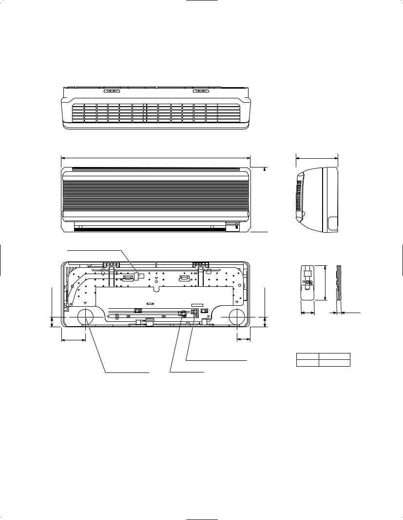
3-1-1. Indoor Unit
(1) Indoor unit KS0951 / KS1251
31-11/16 (805)
 10-5/8 (270)
Drain hose ø23/32 (18)
1-5/8 (41.0) |
1-5/8 (41.0) |
3-29/32 |
2-5/16 |
(99.5) |
(58.5) |
|
Narrow tube ø1/4 (6.35) |
Center of tubing |
Wide tube* |
hole (2 places) |
6-31/32 (177)
Remote control unit
6-7/32 |
(172.5) |
2-2/5 |
25/32 |
(61)(18.5)
*
KS0951 ø3/8 (9.52)
KS1251 ø1/2 (12.7)
Unit: inch (mm)
13

(2) Indoor unit KS1852
39-3/16 (995)
|
11-7/32 (285) |
|
|
|
7-23/32 (196) 1/8 (3) |
|
|
Remote control unit |
-25/32 (45) |
-25/32 (45) |
6-7/32 (172.5) |
1 |
1 |
|
|
|
|
2-2/5 |
25/32 |
(147.5) |
|
(147.5) |
(61) |
(18.5) |
|
|
|
||
5-13/16 |
Center of tubing |
5-13/16 |
|
|
|
hole (2 places) |
Drain hose ø25/32 (18) |
|
|
|
Narrow tube ø1/4 (6.35) |
|
|
|
|
Wide tube ø5/8 (15.88) |
|
|
Unit : inch (mm) |
14
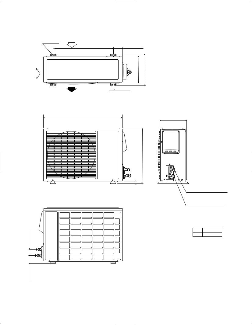
3-1-2. Outdoor Unit
(1) Outdoor unit C0951 / CL0951 / C1251 / CL1251
Air intake
2-ø15/32"
23-15/16" 3-25/32"
11-13/32" |
12-7/16" |
15/32"
Air discharge
31-2/1"
11-13/32"
21-1/4"
5/8"
Narrow tube service valve
ø1/4 (6.35)
Wide tube service valve*
2-5/32"
3-7/16"
*
0951 ø3/8 (9.52)
1251 ø1/2 (12.7)
Unit: inch (mm)
15
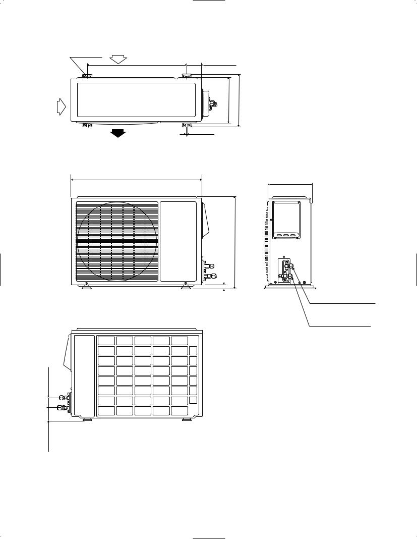
(2) Outdoor unit C1852 / CL1852
Air intake
4-ø15/32"
23-15/16" 5-11/32"
12-7/32" |
13-5/32" |
15/32"
Air discharge
34-21/32"
21-19/32"
5/8"
2-5/32"
3-7/16"
12-19/32"
Narrow tube service valve
ø1/4 (6.35)
Wide tube service valve ø5/8 (15.88)
Unit: inch (mm)
16
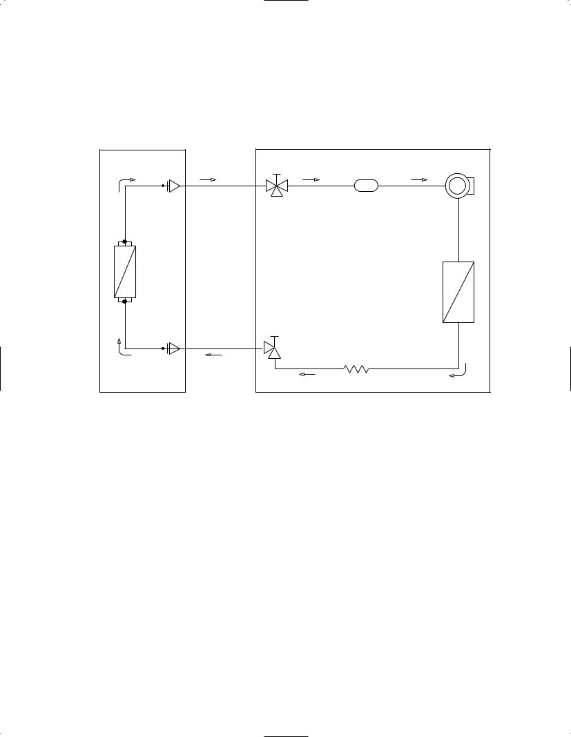
4. REFRIGERANT FLOW DIAGRAM
4-1. Refrigerant Flow Diagram
Indoor unit KS0951 / KS1251 / KS1852
Outdoor unit C0951 / CL0951 / C1251 / CL1251 / C1852 / CL1852
COOLING CYCLE
Indoor unit |
|
Outdoor unit |
|
Wide tube |
Service |
Compressor |
|
valve |
|||
Accumulator |
|||
O.D. |
|
|
|
3/8" (9.52 mm) |
|
|
|
1/2" (12.7 mm) |
|
|
|
5/8" (15.88 mm) |
|
|
|
Heat |
|
|
|
exchanger |
|
|
|
|
|
Condenser |
|
|
Service |
|
|
|
valve |
|
|
Narrow tube |
|
|
|
O.D. |
|
Capillary tube |
|
|
|
||
1/4" (6.35 mm) |
|
|
17
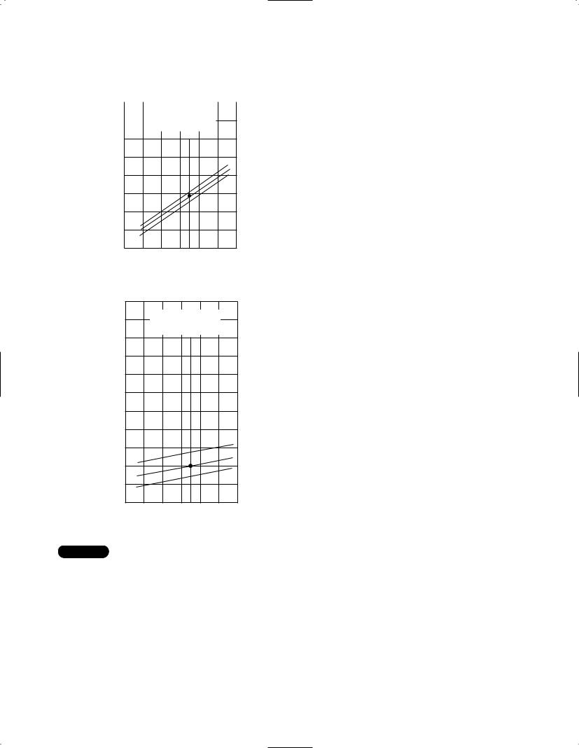
5. PERFORMANCE DATA
5-1. Performance Charts
(1) Indoor unit |
KS0951 |
|||||
Outdoor unit C0951 / CL0951 |
||||||
● Cooling Characteristics |
||||||
|
115 V |
|||||
|
|
|
|
|
|
|
|
|
|
|
|
|
|
13 |
|
Indoor inlet air |
|
|||
|
° ° |
|
||||
|
|
D.B. temp. F ( C) |
|
|||
|
|
|
|
|
|
|
(A) |
12 |
|
|
|
|
|
|
11 |
|
|
|
|
|
95 (35.0) |
|
current |
|
|
|
|
|
||
10 |
|
|
|
|
|
80 (26.7) |
|
|
|
|
|
|
67 (19.4) |
||
Operating |
9 |
|
|
|
|
|
|
8 |
|
|
|
|
|
|
|
7 |
|
|
|
|
|
|
|
|
|
|
|
|
|
|
|
|
6 |
70 |
80 |
90 |
100 |
110 |
120 |
|
60 |
||||||
|
(15.6) (21.1) (26.7) (32.2) (37.8) (43.3) (48.9) |
||||||
Outdoor inlet air D.B. temp. °F (°C)
|
115 V |
150 (10.5) |
Indoor inlet air |
|
D.B. temp. °F (°C) |
|
|
140 |
(9.8) |
|
|
|
|
|
|
G) |
|
130 |
(9.1) |
|
|
|
|
|
|
service valve |
|
|
|
|
|
|
|
|
|
2 |
120 |
(8.4) |
|
|
|
|
|
|
|
psig (kg/cm |
|
|
|
|
|
|
|||
110 |
(7.7) |
|
|
|
|
|
|
||
100 |
(7.0) |
|
|
|
|
|
|
||
pressure |
wide tube |
90 |
(6.3) |
|
|
|
|
|
|
80 |
|
|
|
|
|
|
95 (35.0) |
||
(5.6) |
|
|
|
|
|
80 (26.7) |
|||
Low |
at |
|
|
|
|
|
|
|
|
70 |
(4.9) |
|
|
|
|
|
67 (19.4) |
||
|
|
|
|
|
|
||||
|
|
60 |
(4.2) |
|
|
|
|
|
|
|
|
50 |
(3.5) |
70 |
80 |
90 |
100 |
110 |
120 |
|
|
|
60 |
||||||
|
|
|
(15.6) (21.1) |
(26.7) (32.2) |
(37.8) (43.3) (48.9) |
||||
Outdoor inlet air D.B. temp. °F (°C)
(2) Indoor unit |
KS1251 |
Outdoor unit |
C1251 / CL1251 |
● Cooling Characteristics
115 V
Indoor inlet air 14 D.B. temp. °F (°C)
(A) |
13 |
|
|
|
|
|
|
95 (35.0) |
|
|
|
|
|
|
|
||
12 |
|
|
|
|
|
|
80 (26.7) |
|
current |
|
|
|
|
|
|
||
|
|
|
|
|
|
67 (19.4) |
||
|
|
|
|
|
|
|
||
11 |
|
|
|
|
|
|
|
|
|
|
|
|
|
|
|
|
|
Operating |
10 |
|
|
|
|
|
|
|
9 |
|
|
|
|
|
|
|
|
|
|
|
|
|
|
|
|
|
|
8 |
|
|
|
|
|
|
|
|
7 |
60 |
70 |
80 |
90 |
100 |
110 |
120 |
|
(15.6)(21.1) (26.7) (32.2) |
(37.8)(43.3) (48.9) |
||||||
Outdoor inlet air D.B. temp. °F (°C)
|
115 V |
150 (10.5) |
Indoor inlet air |
|
D.B. temp. °F (°C) |
|
|
140 |
(9.8) |
|
|
|
|
|
|
G) |
|
130 |
(9.1) |
|
|
|
|
|
|
service valve |
|
|
|
|
|
|
|
|
|
2 |
120 |
(8.4) |
|
|
|
|
|
|
|
psig (kg/cm |
|
|
|
|
|
|
|||
110 |
(7.7) |
|
|
|
|
|
|
||
100 |
(7.0) |
|
|
|
|
|
|
||
pressure |
wide tube |
90 |
(6.3) |
|
|
|
|
|
|
80 |
(5.6) |
|
|
|
|
|
95 (35.0) |
||
Low |
at |
|
|
|
|
|
|
|
|
70 |
(4.9) |
|
|
|
|
|
80 (26.7) |
||
|
|
|
|
|
|
|
|
|
67 (19.4) |
|
|
60 |
(4.2) |
|
|
|
|
|
|
|
|
50 |
(3.5) |
70 |
80 |
90 |
100 |
110 |
120 |
|
|
|
60 |
||||||
|
|
|
(15.6) (21.1) (26.7) (32.2) (37.8) (43.3) (48.9) |
||||||
Outdoor inlet air D.B. temp. °F (°C)
NOTE
● … Points of rating condition
Black dots in above charts indicate the following rating conditions. Cooling: Indoor air temperature 80°F D.B. / 67°F W.B.
Outdoor air temperature 95°F D.B.
18
(3) Indoor unit |
KS1852 |
|||||
Outdoor unit C1852 / CL1852 |
||||||
● Cooling Characteristics |
||||||
|
230 V |
|||||
|
|
|
|
|
|
|
|
|
|
|
|
|
|
12 |
|
Indoor inlet air |
|
|||
|
° ° |
|
||||
|
|
D.B. temp. F ( C) |
|
|||
|
|
|
|
|
|
|
(A) |
11 |
|
|
|
|
|
|
10 |
|
|
|
|
|
|
|
current |
|
|
|
|
|
95 (35.0) |
|
|
|
|
|
|
|
||
9 |
|
|
|
|
|
80 (26.7) |
|
|
|
|
|
|
67 (19.4) |
||
Operating |
8 |
|
|
|
|
|
|
7 |
|
|
|
|
|
|
|
6 |
|
|
|
|
|
|
|
|
|
|
|
|
|
|
|
|
5 |
70 |
80 |
90 |
100 |
110 |
120 |
|
60 |
||||||
|
(15.6) (21.1) (26.7) (32.2) (37.8) (43.3) (48.9) |
||||||
Outdoor inlet air D.B. temp. °F (°C)
|
230 / 208 V |
150 (10.5) |
Indoor inlet air |
|
D.B. temp. °F (°C) |
|
|
140 |
(9.8) |
|
|
|
|
|
|
G) |
|
130 |
(9.1) |
|
|
|
|
|
|
service valve |
|
|
|
|
|
|
|
|
|
2 |
120 |
(8.4) |
|
|
|
|
|
|
|
psig (kg/cm |
|
|
|
|
|
|
|||
110 |
(7.7) |
|
|
|
|
|
|
||
100 |
(7.0) |
|
|
|
|
|
|
||
pressure |
wide tube |
90 |
(6.3) |
|
|
|
|
|
|
80 |
(5.6) |
|
|
|
|
|
95 (35.0) |
||
Low |
at |
|
|
|
|
|
|
|
80 (26.7) |
70 |
(4.9) |
|
|
|
|
|
67 (19.4) |
||
|
|
|
|
|
|
|
|||
|
|
60 |
(4.2) |
|
|
|
|
|
|
|
|
50 |
(3.5) |
70 |
80 |
90 |
100 |
110 |
120 |
|
|
|
60 |
||||||
|
|
|
(15.6) (21.1) |
(26.7) (32.2) |
(37.8) (43.3) (48.9) |
||||
Outdoor inlet air D.B. temp. °F (°C)
NOTE
● … Points of rating condition
Black dots in above charts indicate the following rating conditions. Cooling: Indoor air temperature 80°F D.B. / 67°F W.B.
Outdoor air temperature 95°F D.B.
19
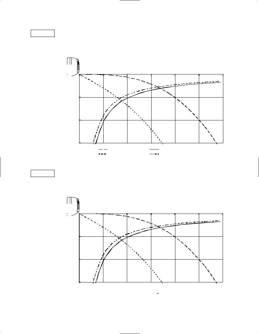
5-2. Air Throw
(1) Indoor unit
Cooling
Room air temp.:
Fan speed:
velocity (ft./sec.) |
distance (ft.) |
Axis air |
Vertical |
(2) Indoor unit
Cooling
Room air temp.:
Fan speed:
0 |
5 |
10 |
15 |
20 |
25 |
30 |
0 |
|
|
|
|
|
|
5 |
|
|
|
|
|
|
10 |
|
|
|
|
|
|
15 |
|
|
|
|
|
|
|
|
|
|
|
|
|
|
: Flap angle 0° , |
|
|
|
|
: Axis air velocity 0° |
|
|
|
|
|
|
|
|
|
|
||||
|
|
|
|
|
|
|
|
: Flap angle 30°, |
|
|
|
|
: Axis air velocity 30° |
|
|
|
|
|
|
|
|
20
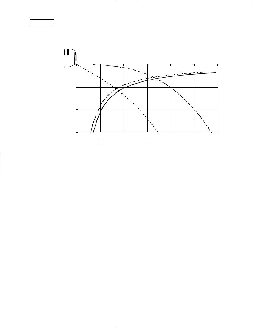
(3) Indoor unit KS1852
Cooling
Room air temp.: 80°F (26.7°C)
Fan speed: |
|
High |
|
|
|
|
|
|
|
|
|
|
Horizontal distance (ft.) |
|
|
||
|
|
0 |
5 |
10 |
15 |
20 |
25 |
30 |
(ft./sec.)velocity |
distance(ft.) |
0 |
|
|
|
|
|
|
5 |
|
|
|
|
|
|
||
|
|
|
|
|
|
|
|
|
airAxis |
Vertical |
10 |
|
|
|
|
|
|
|
|
|
|
|
|
|
|
|
|
|
15 |
|
|
|
|
|
|
|
|
|
|
: Flap angle 0° , |
|
: Axis air velocity 0° |
|
|
|
|
|
|
: Flap angle 30°, |
|
: Axis air velocity 30° |
|
|
21

5-3. Cooling Capacity
(1) Indoor unit |
|
KS0951 |
|
|
|
|
|
|
|
|
|
||
Outdoor unit C0951 / CL0951 |
|
|
|
|
|
|
|
|
|
||||
115V single-phase 60Hz |
|
|
|
|
|
|
|
|
|
||||
|
|
|
|
|
|
|
|
|
|
|
|
||
|
|
Rating Capacity: 9,000 BTU/h |
|
Air Flow Rate: 270 CFM |
|
|
|||||||
|
|
|
|
|
|
|
|
|
|
|
|
|
|
|
|
|
Evaporator |
|
|
|
Condenser |
|
|
|
|
||
|
|
|
|
|
|
|
|
|
|
|
|||
|
Ent. Temp. °F (°C) |
|
|
|
Ambient Temp. °F (°C) |
|
|
||||||
|
|
|
|
|
|
|
|
|
|
|
|
|
|
|
WB |
|
|
DB |
|
|
75 |
85 |
95 |
|
105 |
115 |
|
|
|
|
|
|
(23.9) |
(29.4) |
(35.0) |
|
(40.6) |
(46.1) |
|
||
|
|
|
|
|
|
|
|
|
|||||
|
|
|
|
|
TC |
|
9,120 |
8,680 |
8,170 |
|
7,610 |
6,980 |
|
|
|
|
|
|
|
|
|
|
|
|
|
|
|
|
|
|
|
|
CI |
|
0.65 |
0.71 |
0.77 |
|
0.83 |
0.92 |
|
|
59 |
|
|
72 (22.2) |
SHC |
|
6,670 |
6,450 |
6,190 |
|
5,920 |
5,620 |
|
|
|
|
|
|
|
|
|
|
|
|
|
|
|
|
(15.0) |
|
76 (24.4) |
SHC |
|
7,530 |
7,300 |
7,050 |
|
6,780 |
6,480 |
|
|
|
|
|
|
|
|
|
|
|
|
|
|
|
|
|
|
|
|
80 (26.7) |
SHC |
|
8,420 |
8,200 |
7,940 |
|
7,610 |
6,980 |
|
|
|
|
|
|
|
|
|
|
|
|
|
|
|
|
|
|
|
84 (28.9) |
SHC |
|
9,120 |
8,680 |
8,170 |
|
7,610 |
6,980 |
|
|
|
|
|
|
|
|
|
|
|
|
|
|
|
|
|
|
|
88 (31.1) |
SHC |
|
9,120 |
8,680 |
8,170 |
|
7,610 |
6,980 |
|
|
|
|
|
|
|
|
|
|
|
|
|
|
|
|
|
|
|
|
TC |
|
9,460 |
9,040 |
8,590 |
|
8,070 |
7,520 |
|
|
|
|
|
|
|
|
|
|
|
|
|
|
|
|
|
|
|
|
CI |
|
0.65 |
0.72 |
0.78 |
|
0.85 |
0.94 |
|
|
63 |
|
|
72 (22.2) |
SHC |
|
5,620 |
5,420 |
5,220 |
|
4,980 |
4,740 |
|
|
|
|
|
|
|
|
|
|
|
|
|
|
|
|
(17.2) |
|
76 (24.4) |
SHC |
|
6,480 |
6,280 |
6,070 |
|
5,840 |
5,600 |
|
|
|
|
|
|
|
|
|
|
|
|
|
|
|
|
|
|
|
|
80 (26.7) |
SHC |
|
7,370 |
7,180 |
6,970 |
|
6,740 |
6,490 |
|
|
|
|
|
|
|
|
|
|
|
|
|
|
|
|
|
|
|
84 (28.9) |
SHC |
|
8,230 |
8,030 |
7,830 |
|
7,590 |
7,350 |
|
|
|
|
|
|
|
|
|
|
|
|
|
|
|
|
|
|
|
88 (31.1) |
SHC |
|
9,080 |
8,890 |
8,590 |
|
8,070 |
7,520 |
|
|
|
|
|
|
|
|
|
|
|
|
|
|
|
|
|
|
|
|
TC |
|
9,820 |
9,430 |
#9,000 |
|
8,520 |
8,000 |
|
|
|
|
|
|
|
|
|
|
|
|
|
|
|
|
|
|
|
|
CI |
|
0.66 |
0.72 |
0.79 |
|
0.86 |
0.96 |
|
|
67 |
|
|
72 (22.2) |
SHC |
|
4,560 |
4,400 |
4,220 |
|
4,020 |
3,810 |
|
|
|
|
|
|
|
|
|
|
|
|
|
|
|
|
(19.4) |
|
76 (24.4) |
SHC |
|
5,420 |
5,250 |
5,070 |
|
4,880 |
4,670 |
|
|
|
|
|
|
80 (26.7) |
SHC |
|
6,320 |
6,150 |
5,970 |
|
5,770 |
5,560 |
|
|
|
|
|
|
|
|
|
|
|
|
|
|
|
|
|
|
|
84 (28.9) |
SHC |
|
7,170 |
7,010 |
6,830 |
|
6,630 |
6,420 |
|
|
|
|
|
|
|
|
|
|
|
|
|
|
|
|
|
|
|
88 (31.1) |
SHC |
|
8,030 |
7,860 |
7,680 |
|
7,480 |
7,270 |
|
|
|
|
|
|
|
|
|
|
|
|
|
|
|
|
|
|
|
|
TC |
|
10,340 |
9,980 |
9,590 |
|
9,170 |
8,700 |
|
|
|
|
|
|
|
|
|
|
|
|
|
|
|
|
|
|
|
|
CI |
|
0.67 |
0.73 |
0.8 |
|
0.88 |
0.98 |
|
|
71 |
|
|
72 (22.2) |
SHC |
|
3,520 |
3,380 |
3,230 |
|
3,070 |
2,890 |
|
|
|
|
|
|
|
|
|
|
|
|
|
|
|
|
(21.7) |
|
76 (24.4) |
SHC |
|
4,370 |
4,230 |
4,080 |
|
3,920 |
3,750 |
|
|
|
|
|
|
|
|
|
|
|
|
|
|
|
|
|
|
|
|
80 (26.7) |
SHC |
|
5,270 |
5,130 |
4,980 |
|
4,820 |
4,640 |
|
|
|
|
|
|
|
|
|
|
|
|
|
|
|
|
|
|
|
84 (28.9) |
SHC |
|
6,120 |
5,980 |
5,830 |
|
5,680 |
5,500 |
|
|
|
|
|
88 (31.1) |
SHC |
|
6,980 |
6,840 |
6,690 |
|
6,530 |
6,360 |
|
|
|
|
|
|
|
|
|
|
|
|
|
|
|
|
|
|
|
|
TC |
|
10,550 |
10,210 |
9,850 |
|
9,430 |
8,990 |
|
|
|
|
|
|
|
|
|
|
|
|
|
|
|
|
|
|
|
|
CI |
|
0.68 |
0.74 |
0.81 |
|
0.9 |
1 |
|
|
75 |
|
|
76 (24.4) |
SHC |
|
3,240 |
3,120 |
3,000 |
|
2,850 |
2,710 |
|
|
|
|
|
|
|
|
|
|
|
|
|
|
|
|
(23.9) |
|
80 (26.7) |
SHC |
|
4,140 |
4,020 |
3,890 |
|
3,750 |
3,600 |
|
|
|
|
|
|
|
|
|
|
|
|
|
|
|
|
|
|
|
|
84 (28.9) |
SHC |
|
4,990 |
4,870 |
4,750 |
|
4,610 |
4,460 |
|
|
|
|
|
|
|
|
|
|
|
|
|
|
|
|
|
|
|
88 (31.1) |
SHC |
|
5,850 |
5,730 |
5,610 |
|
5,460 |
5,310 |
|
|
TC |
: Total cooling capacity (BTU/h) |
|
|
|
|
|
|
|||||
|
SHC : Sensible heat capacity (BTU/h) |
|
|
|
|
|
|
||||||
|
CI |
: Compressor input (kW) |
|
|
|
|
|
|
|
||||
|
Rating conditions (# mark) are: Outdoor ambient temperature |
|
95°F (35°C) D.B. |
||||||||||
|
|
|
|
|
Indoor unit entering air temperature |
80°F (26.7°C) D.B./67°F (19.4°C) W.B. |
|||||||
22
 Loading...