


For Indoor Unit
INSTALLATION INSTRUCTIONS
– Inverter Split System Air Conditioner – COOL/DRY/HEAT Model
This air conditioner uses the new refrigerant R410A.
Contents
|
|
|
Page |
IMPORTANT! |
|
||
Please Read Before Starting .................................. |
2 |
||
1. |
GENERAL .......................................................... |
3 |
|
|
1-1. Tools Required for Installation (not supplied) |
||
|
1-2. Accessories Supplied with Unit |
|
|
|
1-3. Optional Copper Tubing Kit |
|
|
|
1-4. Type of Copper Tube and Insulation Material |
||
|
1-5. Additional Materials Required for Installation |
||
2. |
INSTALLATION SITE SELECTION ................... |
4 |
|
|
2-1. |
Indoor Unit |
|
|
2-2. Embedding the Tubing and Wiring |
|
|
3. |
HOW TO INSTALL THE INDOOR UNIT .............. |
6 |
|
|
3-1. Remove the Rear Panel from the Unit |
|
|
|
3-2. |
Make a Hole |
|
|
3-3. Install the Rear Panel on the Wall |
|
|
|
3-4. Remove the Grille to Install the Indoor Unit |
||
|
3-5. Shape the Indoor Side Tubing |
|
|
|
3-6. |
Wiring Instructions |
|
|
3-7. Wiring Instructions for Inter-unit Connections |
||
|
3-8. |
Mounting |
|
|
3-9. |
Drain Hose |
|
4. |
HOW TO TEST RUN THE AIR CONDITIONER .... |
16 |
|
5.REMOTE CONTROL UNIT INSTALLATION
POSITION ......................................................... |
17 |
|
5-1. |
Mounting on a Wall |
|
6. ADDRESS SWITCH .......................................... |
18 |
|
6-1. |
Address Setting of the Remote |
|
|
Control Unit |
|
7.CONNECTING A HOME AUTOMATION
DEVICE.............................................................. |
19 |
8. INSTALLATION CHECK SHEET ...................... |
19 |
Model Combinations
Combine indoor and outdoor units only as listed below.
Indoor Unit |
Outdoor Unit |
KMHS0772 |
CMH1972 |
KMHS0972 |
CMH2472 |
KMHS1272 |
CMH3172 |
KMHS1872 |
|
KMHS2472 |
|
Power Source:
60 Hz, single-phase, 230 / 208 VAC
Combinations of indoor and outdoor units
Connect indoor and outdoor units only in the combinations listed in the catalog or installation manual.
CAUTION
Connecting any other model may result in operation failure and system damage.
Be sure to read the yellow instruction sheet attached to the outdoor unit for models using the new refrigerant R410A.
NOTE
The illustrations are based on the typical appearance of a standard model. Consequently, the shape may differ from that of the air conditioner that you are installing.
|
|
In Canada |
|
SANYO FISHER COMPANY |
SANYO Canada Inc. |
|
A DIVISION OF SANYO NORTH AMERICA CORPORATION |
300 Applewood Crescent, Concord |
|
21605 Plummer Street |
Ontario, L4K 5C7, Canada |
85264189998000 © SANYO 2006 |
Chatsworth, CA 91311 U.S.A. |
|
IMPORTANT!
Please Read Before Starting
This air conditioning system meets strict safety and operating standards. As the installer or service person, it is an important part of your job to install or service the system so it operates safely and efficiently.
For safe installation and trouble-free operation, you must:
●Carefully read this instruction booklet before beginning.
●Follow each installation or repair step exactly as shown.
●Observe all local, state, and national electrical codes.
●Pay close attention to all warning and caution notices given in this manual.
This symbol refers to a hazard
or unsafe practice which can WARNING result in severe personal injury
or death.
This symbol refers to a hazard or unsafe practice which can
CAUTION result in personal injury or product or property damage.
If Necessary, Get Help
These instructions are all you need for most installation sites and maintenance conditions. If you require help for a special problem, contact our sales/service outlet or your certified dealer for additional instructions.
In Case of Improper Installation
The manufacturer shall in no way be responsible for improper installation or maintenance service, including failure to follow the instructions in this document.
SPECIAL PRECAUTIONS
 WARNING When Wiring
ELECTRICAL SHOCK CAN CAUSE SEVERE PERSONAL INJURY OR DEATH. ONLY A QUALIFIED, EXPERIENCED ELECTRICIAN SHOULD ATTEMPT TO WIRE THIS SYSTEM.
•Do not supply power to the unit until all wiring and tubing are completed or reconnected and checked.
•Highly dangerous electrical voltages are used in this system. Carefully refer to the wiring diagram and these instructions when wiring. Improper connections and inadequate grounding can cause accidental injury or death.
•Ground the unit following local electrical codes.
•Connect all wiring tightly. Loose wiring may cause overheating at connection points and a possible fire hazard.
When Transporting
Be careful when picking up and moving the indoor and outdoor units. Get a partner to help, and bend your knees when lifting to reduce strain on your back. Sharp edges or thin aluminum fins on the air conditioner can cut your fingers.
When Installing…
…In a Ceiling or Wall
Make sure the ceiling/wall is strong enough to hold the unit’s weight. It may be necessary to construct a strong wood or metal frame to provide added support.
…In a Room
Properly insulate any tubing run inside a room to prevent “sweating” that can cause dripping and water damage to walls and floors.
When Connecting Refrigerant Tubing
•Do not add any refrigerant, air, or substance into the refrigeration circuit other than the designated refrigerant (R410A). Adding anything other than the specified refrigerant may cause the pressure to rise excessively in the refrigeration circuit, rupturing the circuit and causing injury or damage.
•Use all-new tubing and flare nuts to make the tubing connections. Using any previous parts (from R22-based systems) may result in damage to the equipment, and may lead to the refrigeration circuit rupturing, causing a serious accident.
•Apply refrigerant lubricant to the matching surfaces of the flare and union tubes before connecting them, then tighten the nut with a torque wrench for a leak-free connection.
•Check carefully for leaks before starting the test run.
When Servicing
•Turn the power OFF at the main power box (mains) before opening the unit to check or repair electrical parts and wiring.
•Keep your fingers and clothing away from any moving parts.
•Clean up the site after you finish, remembering to check that no metal scraps or bits of wiring have been left inside the unit being serviced.
Others
CAUTION
•Ventilate any enclosed areas when installing or testing the refrigeration system. Escaped refrigerant gas, on contact with fire or heat, can produce dangerously toxic gas.
•Confirm upon completing installation that no refrigerant gas is leaking. If escaped gas comes in contact with a stove, gas water heater, electric room heater or other heat source, it can produce dangerously toxic gas.
2
1. General
This booklet briefly outlines where and how to install the air conditioning system. Please read over the entire set of instructions for the indoor and outdoor units and make sure all accessory parts listed are with the system before beginning.
1-1. Tools Required for Installation (not supplied)
1.Standard screwdriver
2.Phillips head screwdriver
3.Knife or wire stripper
4.Tape measure
5.Carpenter’s level
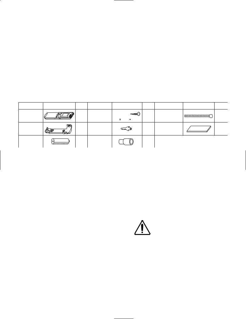
1-2. Accessories Supplied with Unit Table 1
6.Sabre saw or key hole saw
7.Hacksaw
8.Core bits
9.Hammer
10.Drill
11.Tube cutter
12.Tube flaring tool
13.Torque wrench
14.Adjustable wrench
15.Reamer (for deburring)
Parts |
Figure |
Qʼty |
Parts |
Figure |
Qʼty |
Parts |
Figure |
Qʼty |
Remote |
|
|
Tapping screw |
Truss-head |
|
|
|
|
|
1 |
Phillips |
10 |
Clamp |
|
1 |
||
control unit |
|
|
||||||
|
|
|
|
5/32 5/8" (4 16 mm) |
|
|
|
|
Remote control |
|
1 |
Rawl plug |
|
8 |
Air clean filter |
|
2 |
unit holder |
|
|
|
|||||
|
|
|
|
|
|
|
|
|
AAA alkaline |
|
|
Drain hose |
|
|
|
Packed in the indoor unit. |
|
|
2 |
|
1 |
|
|
|
||
battery |
|
adapter |
|
|
|
|
||
|
|
|
|
|
|
|
||
1-3. Optional Copper Tubing Kit |
2. Foamed polyethylene insulation for the specified |
|
Copper tubing for connecting the outdoor unit to the |
copper tubes as required to precise length of tubing. |
|
Wall thickness of the insulation should be not less |
||
indoor unit is available in kits which contain the narrow |
||
than 5/16" (8 mm). |
||
and wide tubing, fittings and insulation. Consult your |
||
|
||
nearest sales outlet or A/C workshop. |
3. Use insulated copper wire for field wiring. Wire size |
|
1-4. Type of Copper Tube and Insulation Material |
varies with the total length of wiring. Refer to 3-6. |
|
Wiring Instructions for details. |
||
If you wish to purchase these materials separately from |
||
|
||
a local source, you will need: |
|
1.Deoxidized annealed copper tube for refrigerant tubing as detailed in Table 2.
Cut each tube to the appropriate lengths 1' to 1'4" |
|
CAUTION |
Check local electrical codes |
||||
(30 cm to 40 cm) to dampen vibration between units. |
|
|
|
and regulations before |
|||
|
|
|
|||||
Table 2 |
|
|
|
|
|
|
obtaining wire. Also, check |
|
|
|
|
|
|
any specified instructions or |
|
|
|
|
|
|
|
|
|
|
|
|
|
|
|
limitations. |
|
Model |
Narrow Tube |
Wide Tube |
|
||||
|
|
|
|
|
|
|
|
Outer Dia. |
Thickness |
Outer Dia. |
Thickness |
|
|
||
|
|
|
|||||
|
|
|
|
|
|
|
|
KMHS0772 |
1/4" (6.35 mm) |
0.0314" (0.8 mm) |
3/8" (9.52 mm) |
0.0314" (0.8 mm) |
|
|
|
|
|
|
|
|
|
|
|
KMHS0972 |
1/4" (6.35 mm) |
0.0314" (0.8 mm) |
3/8" (9.52 mm) |
0.0314" (0.8 mm) |
|
|
|
|
|
|
|
|
|
|
|
KMHS1272 |
1/4" (6.35 mm) |
0.0314" (0.8 mm) |
3/8" (9.52 mm) |
0.0314" (0.8 mm) |
|
|
|
|
|
|
|
|
|
|
|
KMHS1872 |
1/4" (6.35 mm) |
0.0314" (0.8 mm) |
1/2" (12.70 mm) |
0.0314" (0.8 mm) |
|
|
|
|
|
|
|
|
|
|
|
KMHS2472 |
1/4" (6.35 mm) |
0.0314" (0.8 mm) |
5/8" (15.88 mm) |
0.0393" (1.0 mm) |
|
|
|
|
|
|
|
|
|
|
|
3
1-5. Additional Materials Required for Installation
1.Refrigeration (armored) tape
2.Insulated staples or clamps for connecting wire (See local codes)
3.Putty
4.Refrigeration lubricant
5.Clamps or saddles to secure refrigerant tubing
Indoor unit
2. Installation Site Selection
2-1. Indoor Unit
WARNING
AVOID:
To prevent abnormal heat generation and the possibility of fire, do not place obstacles, enclosures and grilles in front of or surrounding the air conditioner in a way that may block air flow.
●direct sunlight.
●nearby heat sources that may affect performance of the unit.
●areas where leakage of flammable gas may be expected.
●placing or allowing any obstructions near the A/C inlet or outlet.
●installing in rooms that contain instant-on (rapid-start) fluorescent lamps. (These may prevent the A/C from receiving signals.)
●places where large amounts of oil mist exist.
●installing in locations where there are devices that generate high-frequency emissions.
DO:
●select an appropriate position from which every corner of the room can be uniformly cooled. (High on a wall is best.)
●select a location that will hold the weight of the unit.
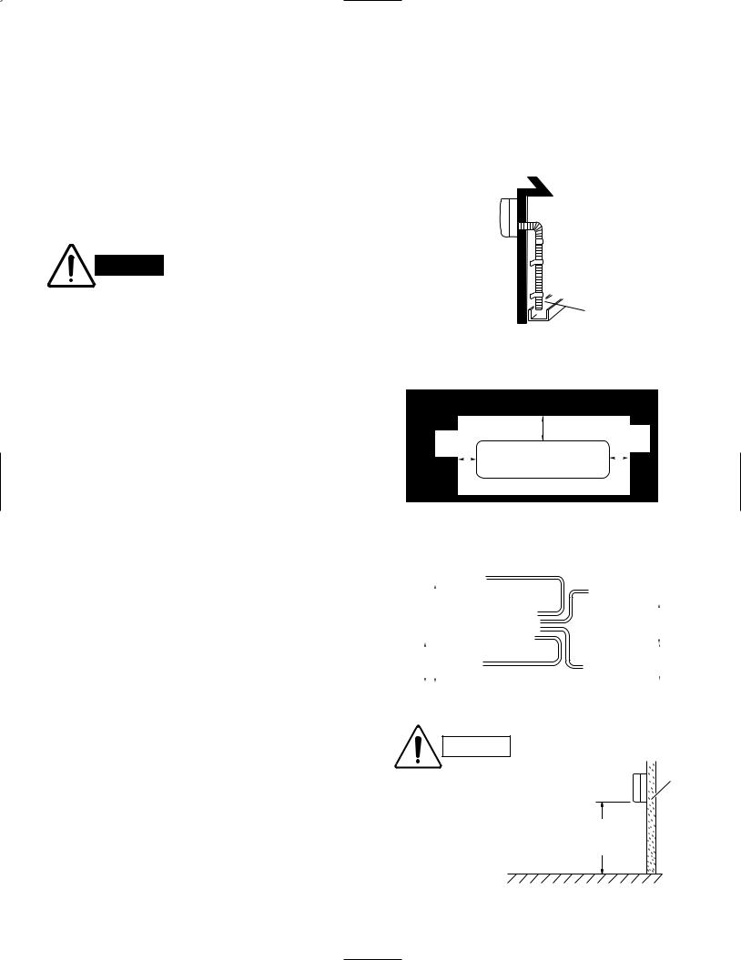
●select a location where tubing and drain hose have the shortest run to the outside. (Fig. 1)
●allow room for operation and maintenance as well as unrestricted air flow around the unit. (Fig. 2)
●install the unit within the maximum elevation difference (H1, H2, H3, H4) above or below the outdoor unit and within a total tubing length (L1+L2+L3, L1+L2+L3+L4) from the outdoor unit as detailed in Table 3 and Fig. 3a.
 Drain hose
Outside drainage
Fig. 1
|
|
|
|
|
|
|
|
|
|
|
|
|
|
6" (15 cm) |
2" (5 |
|
cm) |
|
|
|
||
|
|
|
|
|
|
|
|
|
|
|
|
|
|
|
|
|||||||
|
|
|
|
|
2" (5 |
cm) |
|
|
min. |
|
|
|
|
|||||||||
|
|
|
|
|
|
|
|
|
|
min. |
|
|
|
|||||||||
|
|
|
|
|
|
|
min. |
|
|
|
|
|
|
|
|
|||||||
|
|
|
|
|
|
|
|
Front View |
|
|
|
|
|
|
|
|||||||
|
|
|
|
|
|
|
|
|
|
|
|
|
|
|
|
|
|
|
|
|||
|
|
|
|
|
|
|
|
|
|
|
|
|
|
|
|
|
|
|
|
|||
|
|
|
|
|
|
|
|
|
|
|
|
|
|
|
|
|
|
|
|
|||
|
|
|
|
|
|
|
|
|
|
|
|
|
|
|
|
|
|
|
|
|||
|
|
|
|
|
|
|
|
|
|
|
|
|
Fig. 2 |
|
|
|
|
|
|
|
||
|
|
|
|
|
|
|
|
|
|
Tubing length (L1) |
|
|
|
|
|
|
|
|||||
|
|
|
|
|
INDOOR |
|
|
|
|
|
|
|
|
|||||||||
|
|
|
|
|
UNIT (1) |
|
|
|
|
|
|
|
|
|
|
|
|
|||||
|
|
|
|
|
|
|
|
|
|
|
|
|
|
|
|
INDOOR |
|
|
|
|||
|
|
|
|
|
|
|
|
|
|
|
|
|
|
|
|
UNIT (2) |
|
|
|
|||
|
|
|
Elevation |
|
|
|
L2 |
|
|
|
|
|
|
|
||||||||
|
|
|
OUTDOOR |
|
|
|
|
|
|
|
||||||||||||
|
|
|
difference |
(H1) |
|
|
|
|
|
|
|
H2 |
||||||||||
|
|
|
|
|
|
|
|
|
|
|
|
UNIT |
|
|
|
|
|
|
|
|
|
|
|
|
|
|
|
|
|
|
|
|
|
|
|
|
|
|
|
|
|
|
|
|
|
|
|
|
|
|
|
|
|
|
|
|
|
|
|
L3 |
|
|
|
|
|
|
|
|
|
|
|
|
|
|
|
|
|
|
|
|
|
|
|
|
|
|
|
|
|
||
|
H4 |
|
|
|
|
INDOOR |
|
L4 |
|
INDOOR |
|
H3 |
||||||||||
|
|
|
|
|
|
|
UNIT (4) |
|
|
UNIT (3) |
|
|
|
|||||||||
Fig. 3a
CAUTION
For stable operation of the air conditioner, do not install wall-mounted type indoor units less than 5' (1.5 m) from floor level.
Indoor unit
Wall
Minimum height from floor level
5' (1.5 m)
Floor level
Fig. 3b
4

●Install the indoor unit more than 3.3' (1 m) away from any antenna or power lines or connecting wires used for television, radio, telephone, security system, or intercom.
Electrical noise from any of these sources may affect operation.
●install in a sturdy manner to avoid increased operating noise.
Table 3
|
Max. |
Max. Allowable Total |
|
Limit of |
Limit of Elevation |
Required Amount |
|
|
Allowable |
Tubing Length |
Total Tubing Length |
Difference |
of Additional |
||
Model |
Tubing Length |
at shipment |
(L1+L2+L3) or |
(H1, H2, H3, H4) |
Refrigerant |
||
|
per unit |
(L1+L2+L3) or |
(L1+L2+L3+L4) |
(ft.) |
(oz./ft.)* |
||
|
(ft.) |
(L1+L2+L3+L4) |
|
(ft.) |
|
|
|
|
|
|
(ft.) |
|
|
|
|
|
|
|
|
|
|
|
|
CMH1972 |
82 |
150 |
(L1+L2+L3) |
150 |
(L1+L2+L3) |
50 |
— |
|
|
|
|
|
|
|
|
CMH2472 |
82 |
150 |
(L1+L2+L3+L4) |
200 |
(L1+L2+L3+L4) |
50 |
0.22 |
|
|
|
|
|
|
|
|
CMH3172 |
100 |
150 |
(L1+L2+L3+L4) |
230 |
(L1+L2+L3+L4) |
50 |
0.22 |
|
|
|
|
|
|
|
|
*If total tubing length becomes 150 to 200 ft. (Max.) or 150 to 230 ft. (Max.), charge additional refrigerant (R410A) by 0.22 oz./ft. No additional charge of compressor oil is necessary.
2-2. Embedding the Tubing and Wiring
●Before beginning embedding installation work, consult fully with agencies or offices related to the building’s foundation, construction, electricity, and water.
●Wait to make connections to the embedded portion. Each connection step is described later in this manual.
●Securely cover the end of the embedded tubing to prevent intrusion of dirt or moisture.
●If an embedded tube is to be left for a long time, fill the tube with nitrogen and seal both ends securely.
If a tube is left open for an extended time, moisture in the air inside the tubing may condense into water droplets, and lead to water contamination of the refrigerant circuit.
●In order to prevent insulation breakdown and ground faults, do not allow wiring ends to come in contact with rainwater, or be subjected to condensation or dew.
●Apply sufficient thermal insulation to the refrigerant tubing and drain pipes.
5

3. How to Install the Indoor Unit
3-1. Remove the Rear Panel from the Unit
(1)Remove and discard the set screw on the rear panel. (Fig. 6)
(2)Press the 2 ▲ marks on the frame cover and disengage the stationary tabs from the frame. (Fig. 7)
(3)Remove the rear panel.
NOTE
Tubing can be extended in 5 directions as shown in Fig. 8. Select the direction you need providing the shortest run to the outside unit.
●When left tubing is to be done, switch the drain hose and drain cap. (For details, refer to “Switching drain hose and drain cap” on page 14.)
3-2. Make a Hole
(1)Place the rear panel from the indoor unit on the wall at the location selected. Make sure the panel is horizontal, using a carpenter’s level or tape measure to measure down from the ceiling. Wait until after cutting the hole before attaching the rear panel to the wall.
(2)Determine which side of the unit you should make the hole for tubing and wiring. (Fig. 9a or 9b)
NOTE
In the case of left-rear tubing, use the measurement points from the edge of the rear panel for precise placement of the hose outlet. (Fig. 9a or 9b)
(3)Before making the hole, check carefully that no studs or pipes are directly run behind the spot to be cut.
Also avoid areas where elec-
CAUTION
trical wiring or conduits are located.
The above precautions are also applicable if tubing goes through the wall in any other location.
Set screw only for transportation
Fig. 6
Rear panel
 marks
marks
Fig. 7
Right-rear tubing
Left (recommended) tubing
Left-rear |
|
tubing |
Right tubing |
|
Downward tubing |
Fig. 8
(KMHS0772, KMHS0972, KMHS1272)
2-3/4" (70 mm)
Fig. 9a
(KMHS1872, KMHS2472)
2-3/8" (60 mm)
Fig. 9b
6
 Loading...