


CH3682
IMPORTANT
These air conditioners employ new
refrigerant R410A.
Pay special attention when
servicing the unit.
TECHNICAL & SERVICE MANUAL
KHS3082 + CH3082
KHS3682 + CH3682
DC INVERTER SPLIT SYSTEM AIR CONDITIONER
Destination: North America
Outdoor Model No.
CH3082
CH3682
Product Code No.
1 852 354 32
1 852 354 33
Indoor Unit Outdoor Unit
KHS3082
KHS3682
CH3082
CH3682
Indoor Model No.
KHS3082
KHS3682
Product Code No.
1 852 354 28
1 852 354 29
REFERENCE NO.
SM700858
FILE NO.
• Before doing repair work, please read the " SAFETY PRECAUTIONS" carefully and fully understand them.
• The precautionary items here are divided into " Warning" and " Caution" items.
Items in particular which may cause death or serious injury to the service personnel if the work is not performed correctly,
are included in the " Warning" table.
However, even precautionary items identified as " Caution" also have the potential for serious consequences
if not performed correctly.
Important safety precautions are described for all items in both categories. Be sure to carefully follow all of them.
• Symbol Indication
: This symbol indicates items to which we need to pay attention.
In this triangle, a definite precautionary item is described.
: This symbol indicates the item to be prohibited.
In or close to this circle, a prohibited item is described.
: This symbol indicates the items requiring special attention or instruction.
In or close to this circle, a prohibited item is described.
• After doing repair work, perform a test run to confirm that there are no abnormalities.
At the same time, explain the precautions in use to the user.
SAFETY PRECAUTIONS
Warning
Before performing an overhaul, disconnect the power plug or power cable from the unit.
Performing the work with the power supplied to the unit, may cause an electric shock.
When repair work or circuit inspection that requires power supply for the air conditioner, is to be performed,
do not touch the charging section.
Doing so may cause an electric shock.
For the step-up capacitor attached to the electric section, perform the repair work after sufficiently discharging it.
Insufficient capacitor discharge may cause an electric shock.
Do not perform repair work on the electric sections with wet hands.
Doing so may cause an electric shock.
Do not start or stop the air conditioner by means of connecting or disconnecting the power plug.
Doing so may cause an electric shock or fire.
When conducting repair work only use components included in the parts list for the corresponding unit and perform
the work with the appropriate tools.
Incorrect or poor repair work may cause an electric shock or fire.
Never modify the unit.
Doing so may cause an electric shock or fire.
Perform all electric work according to local applicable regulations related to electrical equipment or interior wiring
regulation and make sure to use the exclusive circuit.
Insufficient capacity to the electric circuit or defective arrangement results may cause an electric shock or fire.
Make sure to replace any power cable or lead wire showing any signs of scratch or deterioration.
Failure to do so may cause an electric shock, overheating or fire.
Make sure that there is no dust on or slack in the power plug and insert fully into the socket.
Dust or incomplete connections may cause an electric shock or fire.
Do not damage or process the power cord, as it may cause an electric shock or fire.
For the wiring between the indoor unit and outdoor unit, securely fix the specified cable onto the terminal plate.
Poorly fixed wiring may cause a heat or fire.
After connecting the wiring between the indoor unit and outdoor unit, attach the terminal cover securely.
Incomplete attachment of the terminal cover may cause overheating or fire.
Prohibit
Prohibit
Prohibit
Prohibit
Prohibit
2
Warning
If refrigerant gas blows off during the work, do not touch the refrigerant gas as it may cause frostbite.
If refrigerant gas leaks during the work, ventilate the room.
If refrigerant gas catches fire, harmful gas may be generated.
Do not mix any gas other than the specified refrigerant gas in the refrigerating cycle.
If air or other contaminants mix with the gas, pressure will become extremely high in the refrigerating cycle,
which may cause a unit breakdown."
When the welded section of the compressor intake or discharge pipe is to be disconnected, perform it in
a well-ventilated place after sufficiently recovering the refrigerant gas.
Any residue gas may jet out refrigerant or refrigerating machine oil, which may cause an injury.
When the work is to be performed in a high place (About 2 meters or more), make sure to wear a safety helmet,
gloves and safety belt. Insufficient safety gear may cause a serious injury in case of a fall.
When the unit is to be relocated, confirm that the new installation location has sufficient strength for the weight of the unit.
Insufficient strength of the installation location and incomplete installation work may cause an injury due to
the unit falling.
When the remote controller batteries are replaced, dispose of the old batteries out of the reach of children.
If a child swallows a battery, make sure that the child gets immediate medical attention.
Caution
Do not wash the air conditioner with water, as this may cause an electric shock or fire.
For the repair work in places with high humidity or moisture, make sure to ground the unit.
Failure to do so may cause an electric shock.
Confirm that the component attachment position, wiring condition, soldering condition and connector connection
are normal.
If not, it may cause overheating or fire.
Confirm that the temperature around the compressor is not too high, and then perform the repair work.
Failure to do so may cause a burn.
Perform welding work in a place with good ventilation.
If the work is performed in a poorly ventilated area, it might cause a lack of oxygen.
If the installation plate or attachment frame has deteriorated due to corrosion, etc., replace it.
Failure to do so may cause an injury due to the unit falling.
When the cleaning is to be performed, make sure to turn off the power and pull out the plug.
Touching the fan that is rotating at high speed may result in an injury.
When the indoor unit is to be removed, do not place it on an incline.
Doing so may cause wet furniture because water left inside may trickle down.
Do not hold the sharp end of the unit or the aluminum fins, as it may cause an injury to your hand or finger.
After repairs, make sure to measure the insulation resistance and confirm that the value is 1 Mohm or more.
Any insulation error may cause an electric shock.
After repairs, make sure to check the drainage of the indoor unit.
Inappropriate drainage may cause wet furniture and floors due to water leakage.
Prohibit
Prohibit
Prohibit
Prohibit
Prohibit
3

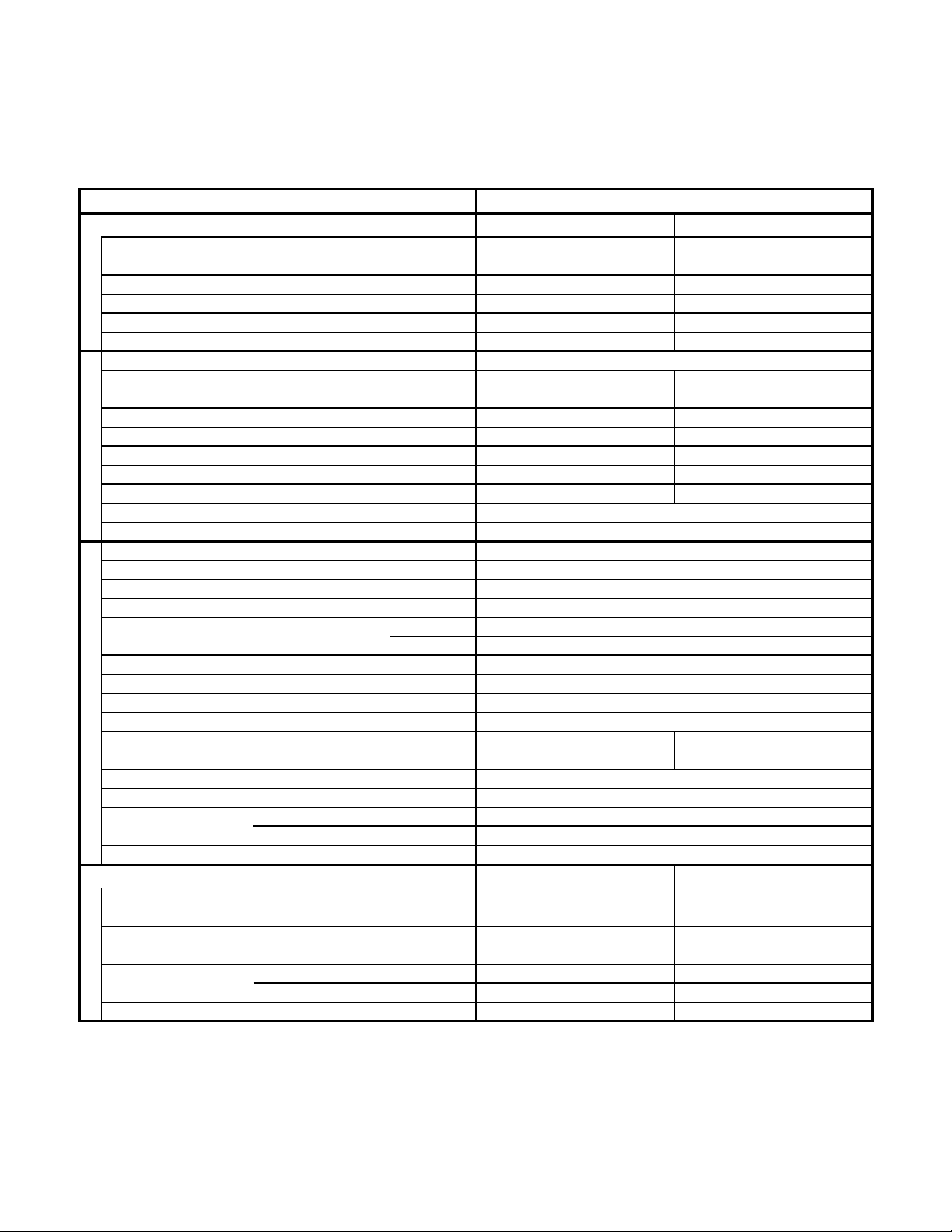
Table of Contents
SAFETY PRECAUTIONS
TABLE OF CONTENTS
1. OPERATING RANGE
2. SPECIFICATIONS
2-1. Unit Specifications
2-2. Major Component Specifications
2-3. Other Component Specifications
3. DIMENSIONAL DATA
4. REFRIGERANT FLOW DIAGRAM
4-1. Refrigerant Flow Diagram
5. PERFORMANCE DATA
5-1. Te mperature Charts
5-2. Cooling Capacity
5-3. Heating Capacity
5-4. Air Throw Distance Charts
6. ELECTRICAL DATA
6-1. Electrical Characteristics
6-2. Electric Wiring Diagrams
7. FUNCTIONS
7-1. Operation Functions
7-2. Protective Functions
8. TROUBLESHOOTING
8-1. Precautions before Performing Inspection or Repair
8-2. Method of Self-Diagnostics
8-3. Checking the Indoor and Outdoor Units
8-4. Trouble Diagnosis of Fan Motor
8-5. Noise Malfunction and Electromagnetic Interference
2
4
6
7
11
15
16
18
19
23
27
29
31
33
35
39
41
41
44
48
50
..............................................................................................................
.....................................................................................................................
...................................................................................................................
.............................................................................................................
.......................................................................................
.......................................................................................
.....................................................................................................................
...................................................................................................
............................................................................................................
................................................................................................................
................................................................................................................
.................................................................................................
....................................................................................................
....................................................................................................
...........................................................................................................
...........................................................................................................
...........................................................
.................................................................................................
..............................................................................
...........................................................................................
..........................................................
Page
4

9. CHECKING ELECTRICAL COMPONENTS
9-1. Measurement of Insulation Resistance
9-2. Checking Continuity of Fuse on PCB Ass'y
10. REFRIGERANT R410A:
SPECIAL PRECAUTIONS WHEN SERVICING UNIT
10-1. Characteristics of New Refrigerant R410A
10-2. Checklist before Servicing
10-3. Tools Specifically for R410A
10-4. Tubing Installation Procedures
10-5. In Case of Compressor Malfunction
10-6. In Case Refrigerant is Leaking
10-7. Charging Additional Refrigerant
10-8. Retro-Fitting Existing Systems
APPENDIX A INSTRUCTION MANUAL
APPENDIX B INSTALLAION INSTRUCTIONS
51
52
53
54
55
55
56
58
59
59
A-1
A-2
...............................................................................
.........................................................................
.........................................................................
...................................................................................................
................................................................................................
............................................................................................
....................................................................................
............................................................................................
..........................................................................................
............................................................................................
..........................................................................................
...............................................................................
Page
5

95 °F D.B. / 71 °F W.B.
67 °F D.B. / 57 °F W.B.
80 °F D.B. / 67 °F W.B.
_
D.B. /
_
W.B.
1. OPERATING RANGE
Maximum
Minimum
Maximum
Minimum
115 °F D.B.
0 °F D.B.
75 °F D.B. / 65 °F W.B.
_
D.B. / 0 °F W.B.
Temperature Indoor Air Intake Temp. Outdoor Air Intake Temp.
Cooling
Heating
6

2. SPECIFICATIONS
2-1. Unit Specifications
Indoor Unit KHS3082
Outdoor Unit CH3082
< 230V >
DATA SUBJECT TO CHANGE WITHOUT NOTICE.
Remarks: Rating conditions are:
Cooling: Indoor air temperature 80°F D.B. / 67°F W.B.
Outdoor air temperature 95°F D.B. / 75°F W.B.
Heating: Indoor air temperature 70°F D.B.
Outdoor air temperature 47°F D.B. / 43°F W.B.
Vertical
dB-A
dB-A
Indoor : Hi/Me/Lo/Qt*
Outdoor : Hi
Air Filter
Compressor
Refrigerant / Amount charged at shipment Ibs (g)
Refrigerant Control
( 14,000 to 33,000 )
( 4.1 to 9.7 )
16.5
3,290
( 5.0 to 16.5 )
( 1,000 to 3,290 )
15.3
3,070
( 4.5 to 15.3 )
( 900 to 3,070 )
30,600
9.0
33,000
9.7
( 10,900 to 30,600 )
( 3.2 to 9.0 )
Shipping Volume
Cooling Heating
18,600
12,000
Net
Shipping
Package Dimensions
Weight
Height × Width × Depth
Height × Width × Depth
Ibs (kg)
Ibs (kg)
cu.ft (m
3
)
(mm)
inch
(mm)
230V Single-Phase 60Hz
inch
-
-
187 to 253
Dimensions & Weight
(*Qt = Quiet mode)
Refrigerant Tubing Connections
Unit Dimensions
Operation Sound
Electrical Rating
Sensible Capacity
Latent Capacity
WPower Input
V
A
Available Voltage Range
Running Amperes
Refrigerant Tube Kit / Accessories
Narrow tube
Wide tube
Refrigerant inch (mm)
Tube Diameter inch (mm)
32.0
39.7
4.59
(14.5)
(18.0)
(0.13)
185.2
207.2
15.88
(84.0)
(94.0)
(0.45)
42-3/8 × 40 × 16-3/8
(1,076 × 1,016 × 416)
(300 × 1,065 × 230) (910 × 940 × 340)
12-7/32 × 44-7/8 × 14-31/32
(310 × 1,140 × 380)
Outdoor UnitIndoor Unit
11-13/16 × 41-15/16 × 9-1/16 35-13/16 × 37-1/32 × 13-3/8
3/8 (9.52)
5/8 (15.88)
ft (m)Max. allowable tubing length at shipment
Flare Type
164 (50)
49 / 44 / 39 / 3249 / 44 / 39 / 32
5555
R410A / 6.5 (2,950)
Electric Expansion Valve
Washable, Anti-Mold
DC Twin Rotary (Inverter)
Manual
Auto
Timer
Indoor / OutdoorFan Speeds
24-Hour ON or OFF Timer, 1-Hour OFF Timer
Auto and 3 steps / Auto (Hi, Me, Lo)
Airflow Direction (Indoor) Horizontal
Controls / Temperature Control
Control Unit
Microprocessor / I.C. Thermister
Wireless Remote Control Unit
Features
HSPF
Compressor Locked Rotor Amperes
BTU/Wh
Optional / Air Clean Filter
BTU/h
Performance
- 9.0
%Power Factor 87 87
A 31.0
Voltage Rating
BTU/h
kW
Total Capacity
BTU/h
SEER BTU/Wh 16.0 -
630 (1,070) 671 (1,140)Air Circulation (High) ft
3
/min (m
3
/h)
9.57 -Moisture Removal (High) Pints/h
COP W/W - 3.15
EER BTU/h/W 9.30 -
Fuse or Circuit Breaker Capacity A35
7

Indoor Unit KHS3082
Outdoor Unit CH3082
< 208V >
DATA SUBJECT TO CHANGE WITHOUT NOTICE.
Remarks: Rating conditions are:
Cooling: Indoor air temperature 80°F D.B. / 67°F W.B.
Outdoor air temperature 95°F D.B. / 75°F W.B.
Heating: Indoor air temperature 70°F D.B.
Outdoor air temperature 47°F D.B. / 43°F W.B.
Vertical
dB-A
dB-A
Indoor : Hi/Me/Lo/Qt*
Outdoor : Hi
Air Filter
Compressor
Refrigerant / Amount charged at shipment Ibs (g)
Refrigerant Control
Shipping Volume
Net
Shipping
Package Dimensions
Weight
Height × Width × Depth
Height × Width × Depth
Ibs (kg)
Ibs (kg)
cu.ft (m
3
)
(mm)
inch
(mm)
208V Single-Phase 60Hz
inch
Dimensions & Weight
(*Qt = Quiet mode)
Refrigerant Tubing Connections
Unit Dimensions
Operation Sound
Electrical Rating
Sensible Capacity
Latent Capacity
WPower Input
V
A
Available Voltage Range
Running Amperes
Refrigerant Tube Kit / Accessories
Narrow tube
Wide tube
Refrigerant inch (mm)
Tube Diameter inch (mm)
ft (m)Max. allowable tubing length at shipment
Timer
Indoor / OutdoorFan Speeds
Airflow Direction (Indoor) Horizontal
Controls / Temperature Control
Control Unit
Features
HSPF
Compressor Locked Rotor Amperes
BTU/Wh
BTU/h
Performance
%Power Factor
A
Voltage Rating
BTU/h
kW
Total Capacity
BTU/h
SEER BTU/Wh
Air Circulation (High) ft
3
/min (m
3
/h)
Moisture Removal (High) Pints/h
COP W/W
EER BTU/h/W
Fuse or Circuit Breaker Capacity A
( 14,000 to 33,000 )
( 4.1 to 9.7 )
18.0
3,290
( 5.0 to 18.0 )
( 1,000 to 3,290 )
16.8
3,070
( 4.5 to 16.8 )
( 900 to 3,070 )
30,600
9.0
33,000
9.7
( 10,900 to 30,600 )
( 3.2 to 9.0 )
Cooling Heating
18,600
12,000
-
-
187 to 253
32.0
39.7
4.59
(14.5)
(18.0)
(0.13)
185.2
207.2
15.88
(84.0)
(94.0)
(0.45)
(300 × 1,065 × 230) (910 × 940 × 340)
Outdoor UnitIndoor Unit
11-13/16 × 41-15/16 × 9-1/16 35-13/16 × 37-1/32 × 13-3/8
3/8 (9.52)
5/8 (15.88)
Flare Type
164 (50)
49 / 44 / 39 / 3249 / 44 / 39 / 32
5555
R410A / 6.5 (2,950)
Electric Expansion Valve
Washable, Anti-Mold
DC Twin Rotary (Inverter)
Manual
Auto
24-Hour ON or OFF Timer, 1-Hour OFF Timer
Auto and 3 steps / Auto (Hi, Me, Lo)
Microprocessor / I.C. Thermister
Wireless Remote Control Unit
Optional / Air Clean Filter
- 9.0
88 88
31.0
16.0 -
630 (1,070) 671 (1,140)
9.57 -
- 3.15
9.30 -
35
42-3/8 × 40 × 16-3/8
(1,076 × 1,016 × 416)
12-7/32 × 44-7/8 × 14-31/32
(310 × 1,140 × 380)
8
Indoor Unit KHS3682
Outdoor Unit CH3682
< 230V >
DATA SUBJECT TO CHANGE WITHOUT NOTICE.
Remarks: Rating conditions are:
Cooling: Indoor air temperature 80°F D.B. / 67°F W.B.
Outdoor air temperature 95°F D.B. / 75°F W.B.
Heating: Indoor air temperature 70°F D.B.
Outdoor air temperature 47°F D.B. / 43°F W.B.
Vertical
dB-A
dB-A
Indoor : Hi/Me/Lo/Qt*
Outdoor : Hi
Air Filter
Compressor
Refrigerant / Amount charged at shipment Ibs (g)
Refrigerant Control
Shipping Volume
Net
Shipping
Package Dimensions
Weight
Height × Width × Depth
Height × Width × Depth
Ibs (kg)
Ibs (kg)
cu.ft (m
3
)
(mm)
inch
(mm)
230V Single-Phase 60Hz
inch
Dimensions & Weight
(*Qt = Quiet mode)
Refrigerant Tubing Connections
Unit Dimensions
Operation Sound
Electrical Rating
Sensible Capacity
Latent Capacity
WPower Input
V
A
Available Voltage Range
Running Amperes
Refrigerant Tube Kit / Accessories
Narrow tube
Wide tube
Refrigerant inch (mm)
Tube Diameter inch (mm)
ft (m)Max. allowable tubing length at shipment
Timer
Indoor / OutdoorFan Speeds
Airflow Direction (Indoor) Horizontal
Controls / Temperature Control
Control Unit
Features
HSPF
Compressor Locked Rotor Amperes
BTU/Wh
BTU/h
Performance
%Power Factor
A
Voltage Rating
BTU/h
kW
Total Capacity
BTU/h
SEER BTU/Wh
Air Circulation (High) ft
3
/min (m
3
/h)
Moisture Removal (High) Pints/h
COP W/W
EER BTU/h/W
Fuse or Circuit Breaker Capacity A
( 14,000 to 36,000 )
( 4.1 to 10.5 )
20.0
4,000
( 5.0 to 20.0 )
( 1,000 to 4,000 )
18.2
3,650
( 4.5 to 18.2 )
( 900 to 3,650 )
34,000
10.0
36,000
10.5
( 10,900 to 34,000 )
( 3.2 to 10.0 )
Cooling Heating
20,700
13,300
-
-
187 to 253
32.0
39.7
4.59
(14.5)
(18.0)
(0.13)
185.2
207.2
15.88
(84.0)
(94.0)
(0.45)
(300 × 1,065 × 230) (910 × 940 × 340)
Outdoor UnitIndoor Unit
11-13/16 × 41-15/16 × 9-1/16 35-13/16 × 37-1/32 × 13-3/8
3/8 (9.52)
5/8 (15.88)
Flare Type
164 (50)
49 / 44 / 39 / 3249 / 44 / 39 / 32
5655
R410A / 6.5 (2,950)
Electric Expansion Valve
Washable, Anti-Mold
DC Twin Rotary (Inverter)
Manual
Auto
24-Hour ON or OFF Timer, 1-Hour OFF Timer
Auto and 3 steps / Auto (Hi, Me, Lo)
Microprocessor / I.C. Thermister
Wireless Remote Control Unit
Optional / Air Clean Filter
- 9.0
87 87
31.0
16.0 -
630 (1,070) 671 (1,140)
10.64 -
- 2.89
8.50 -
45
42-3/8 × 40 × 16-3/8
(1,076 × 1,016 × 416)
12-7/32 × 44-7/8 × 14-31/32
(310 × 1,140 × 380)
9

Indoor Unit KHS3682
Outdoor Unit CH3682
< 208V >
DATA SUBJECT TO CHANGE WITHOUT NOTICE.
Remarks: Rating conditions are:
Cooling: Indoor air temperature 80°F D.B. / 67°F W.B.
Outdoor air temperature 95°F D.B. / 75°F W.B.
Heating: Indoor air temperature 70°F D.B.
Outdoor air temperature 47°F D.B. / 43°F W.B.
Vertical
dB-A
dB-A
Indoor : Hi/Me/Lo/Qt*
Outdoor : Hi
Air Filter
Compressor
Refrigerant / Amount charged at shipment Ibs (g)
Refrigerant Control
Shipping Volume
Cooling Heating
Net
Shipping
Package Dimensions
Weight
Height × Width × Depth
Height × Width × Depth
Ibs (kg)
Ibs (kg)
cu.ft (m
3
)
(mm)
inch
(mm)
208V Single-Phase 60Hz
inch
Dimensions & Weight
(*Qt = Quiet mode)
Refrigerant Tubing Connections
Unit Dimensions
Operation Sound
Electrical Rating
Sensible Capacity
Latent Capacity
WPower Input
V
A
Available Voltage Range
Running Amperes
Refrigerant Tube Kit / Accessories
Narrow tube
Wide tube
Refrigerant inch (mm)
Tube Diameter inch (mm)
ft (m)Max. allowable tubing length at shipment
Timer
Indoor / OutdoorFan Speeds
Airflow Direction (Indoor) Horizontal
Controls / Temperature Control
Control Unit
Features
HSPF
Compressor Locked Rotor Amperes
BTU/Wh
BTU/h
Performance
%Power Factor
A
Voltage Rating
BTU/h
kW
Total Capacity
BTU/h
SEER BTU/Wh
Air Circulation (High) ft
3
/min (m
3
/h)
Moisture Removal (High) Pints/h
COP W/W
EER BTU/h/W
Fuse or Circuit Breaker Capacity A
( 14,000 to 36,000 )
( 4.1 to 10.5 )
21.9
4,000
( 5.0 to 21.9 )
( 1,000 to 4,000 )
19.9
3,650
( 4.5 to 19.9 )
( 900 to 3,650 )
34,000
10.0
36,000
10.5
( 10,900 to 34,000 )
( 3.2 to 10.0 )
20,700
13,300
-
-
187 to 253
32.0
39.7
4.59
(14.5)
(18.0)
(0.13)
185.2
207.2
15.88
(84.0)
(94.0)
(0.45)
(300 × 1,065 × 230) (910 × 940 × 340)
Outdoor UnitIndoor Unit
11-13/16 × 41-15/16 × 9-1/16 35-13/16 × 37-1/32 × 13-3/8
3/8 (9.52)
5/8 (15.88)
Flare Type
164 (50)
49 / 44 / 39 / 3249 / 44 / 39 / 32
5655
R410A / 6.5 (2,950)
Electric Expansion Valve
Washable, Anti-Mold
DC Twin Rotary (Inverter)
Manual
Auto
24-Hour ON or OFF Timer, 1-Hour OFF Timer
Auto and 3 steps / Auto (Hi, Me, Lo)
Microprocessor / I.C. Thermister
Wireless Remote Control Unit
Optional / Air Clean Filter
- 9.0
88 88
31.0
16.0 -
630 (1,070) 671 (1,140)
10.64 -
- 2.89
8.50 -
45
42-3/8 × 40 × 16-3/8
(1,076 × 1,016 × 416)
12-7/32 × 44-7/8 × 14-31/32
(310 × 1,140 × 380)
10
Indoor Unit KHS3082
24BYJ48-1256
Flap Motor
Type Stepping Motor
Rating
Model
Coil Resistance Ohm
(Ambient Temp. 77 °F (25 °C))
Each Pair of Terminal : 200 +/- 7%
DC 12V
Aluminum Plate Fin / Copper Tube
1 and 2
19.5
4.55 (0.423) Face Area
Coil
Rows
Fins Per inch
Heat Exchanger Coil
ft
2
(m
2
)
DATA SUBJECT TO CHANGE WITHOUT NOTICE.
Yes
Control PCB
Control Circuit Fuse
Controls
Part No.
Microprocessor
250V 3A
CB-KHS3082
1 ... D3-15/16 / L32-1 (D100/L838)
RCS-8HVPULS4U
Cross-Flow
DC Motor
SIC-39CVL-D847-10 ... 1
8
-
47
1,370 / 1,450
Internal Controller
Yes
-
-
Fan
Remote Control Unit
Q'ty ... Dia. and Length
Type
inch (mm)
Fan Motor
Nominal Output
Coil Resistance
Rough Measure RPM (Cool / Heat)
Type
Model ... Q'ty
No. of Poles
Safety Device
Type
Over-Current Protection
Over-Heat Protection
(Ambient Temp. 68 °F (20 °C))
Run Capacitor Micro F
VAC
W
Ohm
2-2. Major Component Specifications
2-2-1. Indoor Unit
11

Indoor Unit KHS3682
Flap Motor
Type
Rating
Model
Coil Resistance Ohm
(Ambient Temp. 77 °F (25 °C))
Face Area
Coil
Rows
Fins Per inch
Heat Exchanger Coil
ft
2
(m
2
)
DATA SUBJECT TO CHANGE WITHOUT NOTICE.
Control PCB
Control Circuit Fuse
Controls
Part No.
Microprocessor
250V 3A
CB-KHS3682
Fan
Remote Control Unit
Q'ty ... Dia. and Length
Type
inch (mm)
Fan Motor
Nominal Output
Coil Resistance
Rough Measure RPM (Cool / Heat)
Type
Model ... Q'ty
No. of Poles
Safety Device
Type
(Ambient Temp. 68 °F (20 °C))
Run Capacitor Micro F
VAC
W
Ohm
Over-Current Protection
Over-Heat Protection
24BYJ48-1256
Stepping Motor
Each Pair of Terminal : 200 +/- 7%
DC 12V
Aluminum Plate Fin / Copper Tube
1 and 2
19.5
4.55 (0.423)
1 ... D3-15/16 / L32-1 (D100/L838)
RCS-8HVPULS4U
Cross-Flow
DC Motor
SIC-39CVL-D847-10 ... 1
8
-
47
1,370 / 1,450
Internal Controller
Yes
Yes
-
-
12

Outdoor Unit CH3082
2-2-2. Outdoor Unit
P.C.Board
Circuit Fuse
Controls
Part No.
-
250V 25A
POW-CH3082-B1
Noise Filer P.C.B
Microprocessor
400V 3.5A
CR-CH3082-F
Control P.C.B
-
-
HIC-CH3072R-C1
H.I.C.Board
DATA SUBJECT TO CHANGE WITHOUT NOTICE.
Pints (cc)
-
Micro F
VAC
External Finish Acrylic baked-on enamel finish
FV68S ... 2.98 (1,400)
-
-
Internal Controller
Yes
Aluminum Plate Fin / Copper Tube
2
21.2
Face Area
ft
2
(m
2
)
8.05 (0.748)
Coil
Rows
Fins per inch
Heat Exchanger Coil
SIC-71FW-D8120-4A ... 1
Compressor Oil ... Amount
8
142
750 / 750
Ohm
DC Motor
Type
Compressor Model / Nominal Output
Compressor
Coil Resistance (Ambient Temp. 77 °F (25 °C))
Ohm
DC Twin Rotary (Hermetic)
C-9RVN273H0H / 2,250W
T - R :
T - S :
R - S :
0.169
0.169
0.169
CT (Peak current cut-off control)
Compressor Discharge Temp. Control
Operation cut-off control in abnormal ambient Temp.
Safety Device
Micro F
VAC
Run Capacitor
Crankcase Heater
Yes
Yes
Yes
Overload Relay
CS-7L110
Model
Operation Temp.
Open : 230 °F (110 °C), Close : 203 °F (95 °C)
-
-
230V 30W
1 ... D19-9/32 (D490)
Fan
Propeller
Q'ty ... Dia. inch (mm)
Type
Type
Over- Heat Protection
(Ambient Temp. 68 °F (20 °C))
Fan Motor
Nominal Output
Coil Resistance
Safety Device
Rough Measure RPM (Cool / Heat)
Run Capacitor
Type
Model ... Q'ty
No. of Poles
W
Yes
Over- Current Protection
13
Outdoor Unit CH3682
P.C.Board
Circuit Fuse
Controls
Part No.
-
250V 25A
POW-CH3082-B1
Noise Filer P.C.B
Microprocessor
400V 3.5A
CR-CH3682-F
Control P.C.B
-
-
HIC-CH3072R-C1
H.I.C.Board
DATA SUBJECT TO CHANGE WITHOUT NOTICE.
Pints (cc)
-
Micro F
VAC
External Finish Acrylic baked-on enamel finish
FV68S ... 2.98 (1,400)
-
-
Internal Controller
Yes
Aluminum Plate Fin / Copper Tube
2
21.2
Face Area
ft
2
(m
2
)
8.05 (0.748)
Coil
Rows
Fins per inch
Heat Exchanger Coil
SIC-71FW-D8120-4A ... 1
Compressor Oil ... Amount
8
142
750 / 750
Ohm
DC Motor
Type
Compressor Model / Nominal Output
Compressor
Coil Resistance (Ambient Temp. 77 °F (25 °C))
Ohm
DC Twin Rotary (Hermetic)
C-9RVN273H0H / 2,500W
T - R :
T - S :
R - S :
0.169
0.169
0.169
CT (Peak current cut-off control)
Compressor Discharge Temp. Control
Operation cut-off control in abnormal ambient Temp.
Safety Device
Micro F
VAC
Run Capacitor
Crankcase Heater
Yes
Yes
Yes
Overload Relay
CS-7L110
Model
Operation Temp.
Open : 230 °F (110 °C), Close : 203 °F (95 °C)
-
-
230V 30W
1 ... D19-9/32 (D490)
Fan
Propeller
Q'ty ... Dia. inch (mm)
Type
Type
Over- Heat Protection
(Ambient Temp. 68 °F (20 °C))
Fan Motor
Nominal Output
Coil Resistance
Safety Device
Rough Measure RPM (Cool / Heat)
Run Capacitor
Type
Model ... Q'ty
No. of Poles
W
Yes
Over- Current Protection
14
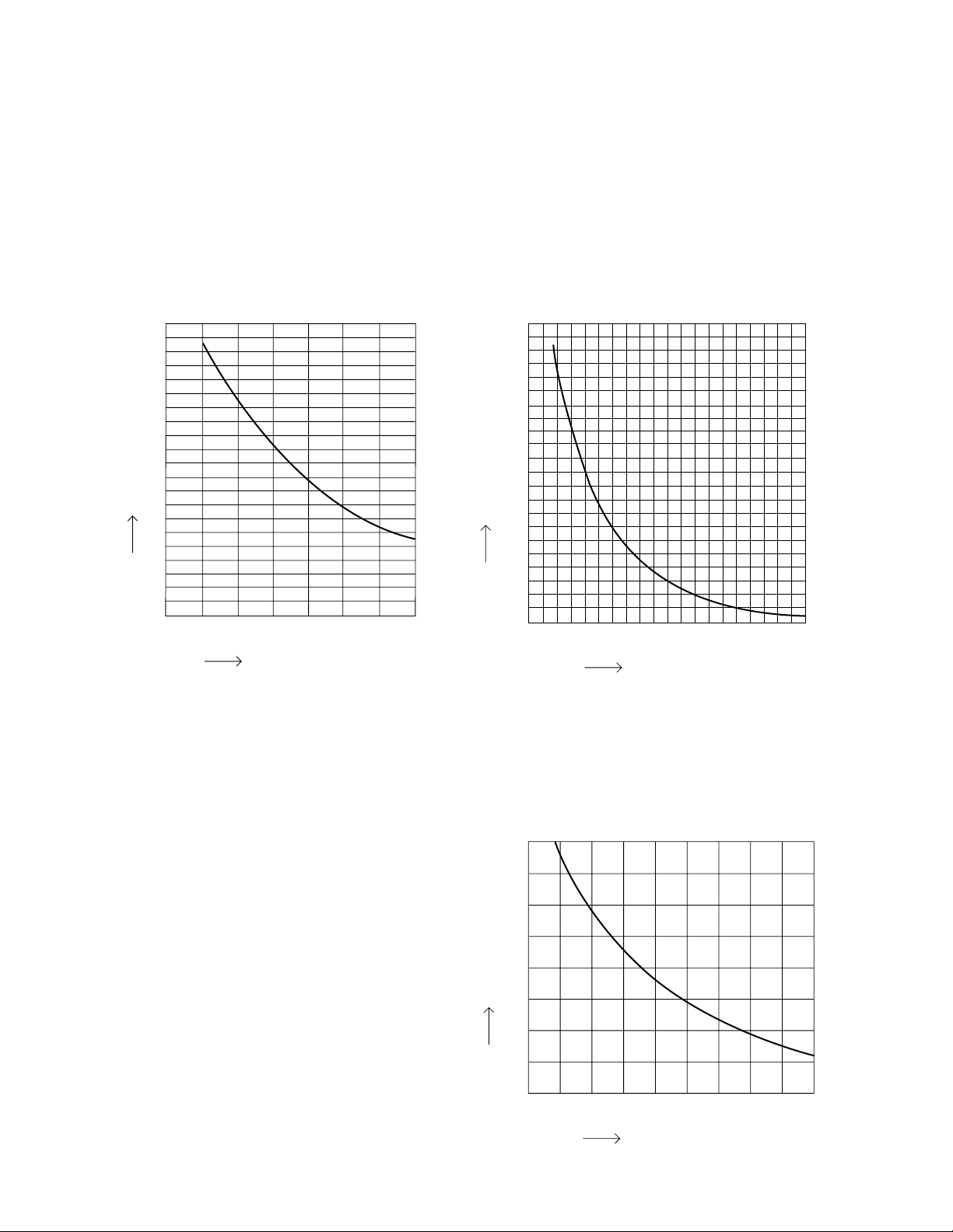
2-3. Other Component Specifications
Indoor Unit KHS3082
KHS3682
Outdoor Unit CH3082
CH3682
0
32 50 68 86 104 122 140 158 176 194
(0) (10) (20) (30) (40) (50) (60) (70) (80) (90)
40
60
80
100
120
140
160
180
200
20
50
1
0
2
3
4
5
6
7
8
9
10
59 68 77 86 95 104
(10) (15) (20) (25) (30) (35) (40)
• Indoor air temp sensor
(Model:KTEC-35-S121-1)
• Indoor heat exchanger sensor
(Model:PTM-D51H-S6-1)
• Compressor temp sensor
(Model:TKS335B)
Resistance (k ohm)
Resistance (k ohm)
Temperature °F (°C)
• Outdoor air temp sensor
(Model:TKS295B)
• Outdoor heat exchanger sensor
(Model:TKS334B)
• Heat sink temp sensor (HIC Board)
(Model:TKS316B)
40
35
30
25
20
15
10
5
0
-
4514 23 32 41 50 59 68
(
-
20)(
-
15)(
-
10) (
-
5) (0) (5) (10) (15) (20)
Resistance (k ohm)
Temperature °F (°C)
Temperature °F (°C)
15
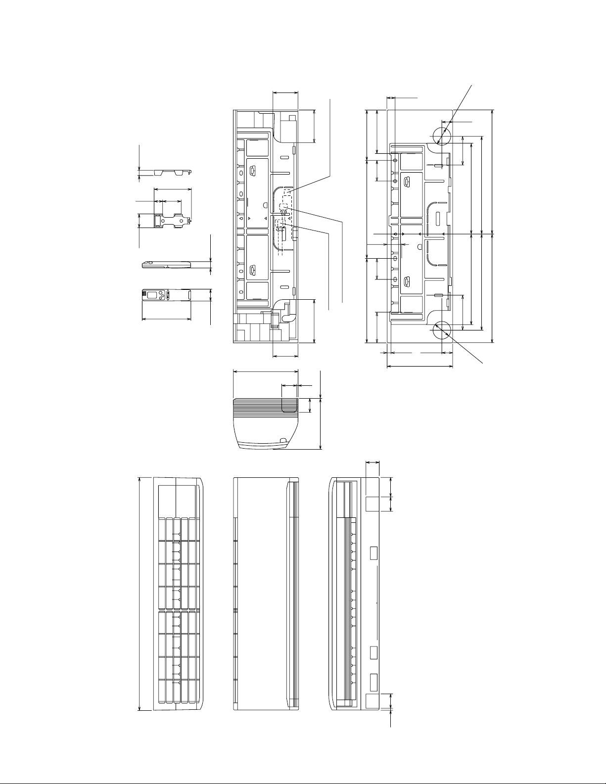
3. DIMENSIONAL DATA
Indoor Unit KHS3082
KHS3682
Unit: inch(mm)
(852-0-0010-19600-0)
41-15/16 (1065)
9-1/16 (230) (3/32)
7-25/32
Wide tube dia. 5/8" (15.88)
Narrow tube dia. 3/8" (9.52)
Drain hose dia. 23/32" (18)
1-27/32 1-3/32
2-3/32 25/32
5-1/2
6-7/32
16-11/32
17-5/16
19-9/16
16-11/32
17-21/32
22-3/8
5-3/16
3-3/4 3-3/4 7-7/8
15-1/8 17-23/32
2-11/16
11-13/16
1-7/8
dia. 3-5/32
23/32
1-15/32
1-7/8
9-3/32
5-27/32
2-3/8
5/16 2-3/4
4-9/16
4-9/16
11-13/16 (300)
7-23/32
2-3/4
5-9/16
1-9/32
7/16
2-5/8
2-3/8
3-3/8
2-5/8
dia. 3-5/32
16
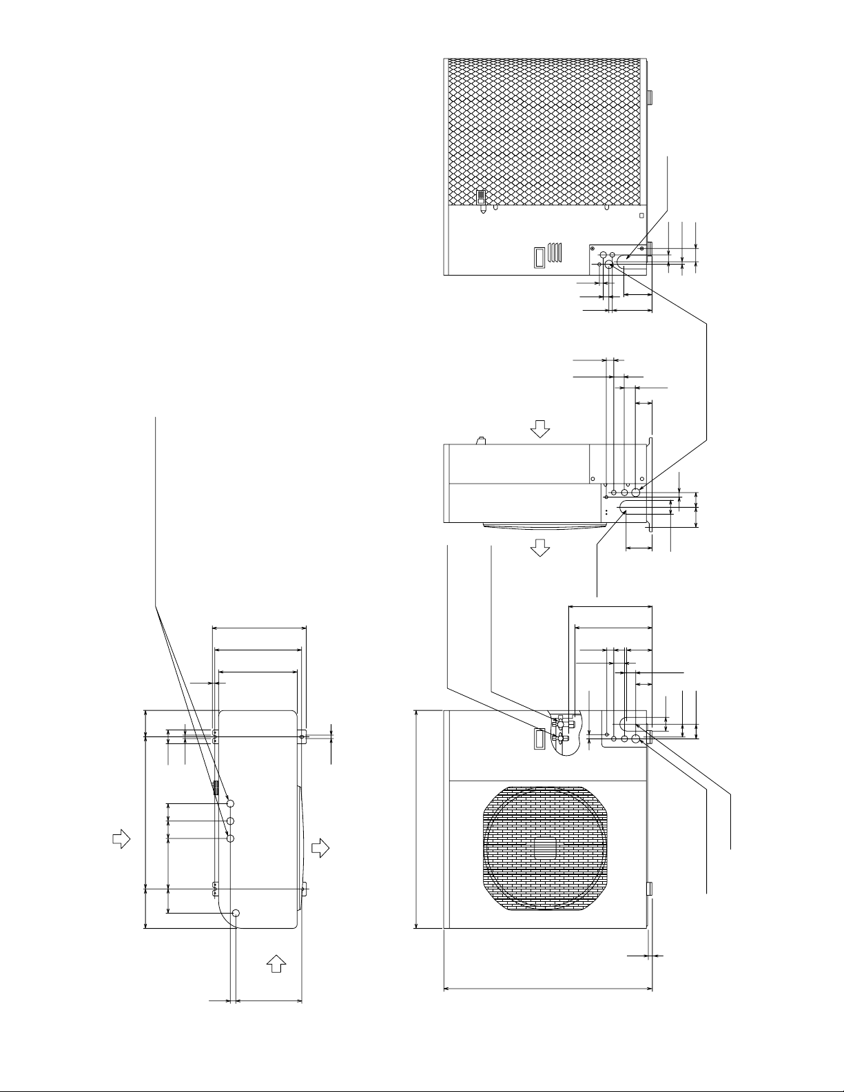
Outdoor Unit CH3082
CH3682
Unit: inch(mm)
(852-0-0010-19400-1)
6-11/6 25-31/32 4-11/32
2-15/16
2-3/8
2-ID:1-1/4 holes (holes for drain)
Of the 4-ID:1-1/4 holes, use 1 of 2 holes
specified for drain use to install the port.
Use rubber plugs to seal the remaining 3 holes.
1/2
1/2
2-15/168-5/84-1/8
37-1/32 (940)
Refrigerant tubing joint (Liquid tube)
Flare connection dia.3/8" (9.52)
Refrigerant tubing joint (Gas tube)
Flare connection dia.5/8" (15.88)
2-3/8
3/4
1-15/16
1-27/32
1-3/16
4-11/32
13-9/32
14-11/32
4-11/32
2-25/32
1-15/16
6-23/32 19/32
31/32
4-3/4
1-3/16
7/16
2-5/32
21/32
1-27/32
1-3/16
2-3/8
Tubing outlet
3/4
3-3/8
2-17/32
Wiring outlet
(knock-out holes
dia.1-3/8, 1-3/32, 7/8, 1/2)
Wiring outlet
(knock-out holes
dia.1-3/8, 1-3/32, 7/8, 1/2)
Tubing outlet
Tubing outlet
2-25/32
2-5/32
2-17/32
35-13/16 (910)
23/32
1-1/32
13/32
13-3/8 (340)
14-31/32
16-5/32
11-13/32
AIR INTAKE
AIR INTAKE
AIR DISCHARGE
AIR DISCHARGE
AIR INTAKE
17
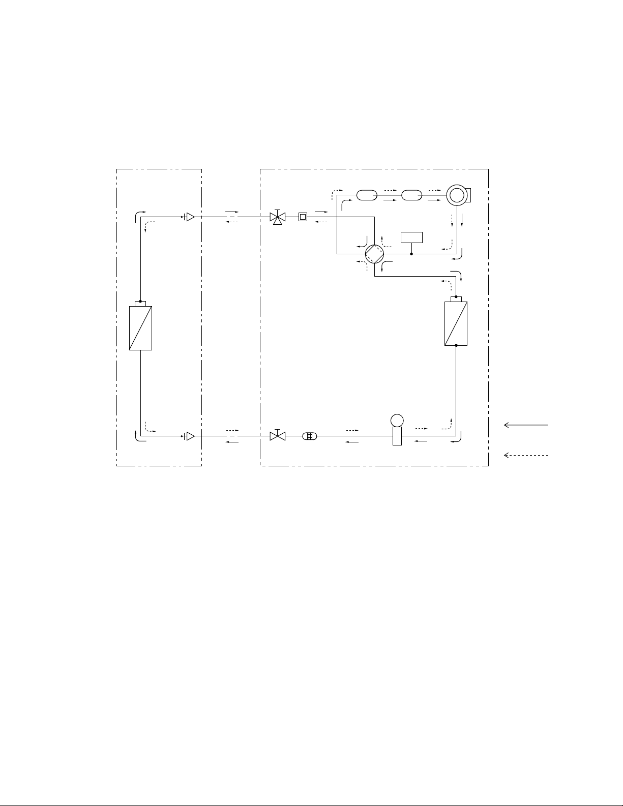
Compressor
4-way
valve
Main
Accumulator
High pressure
switch
Wide tube
service
valve
Wide tube
Sub
Accumulator
Narrow
tube
service
valve
Narrow tube
Heat exchanger
Heat exchanger
Muffler
Cooling cycle
(Defrosting cycle)
Heating cycle
Indoor unit Outdoor unit
Electric
expansion
valve
Strainer
M
O.D
5/8"
(15.88 mm)
O.D.
3/8"
(9.52 mm)
H.P.
4. REFRIGERANT FLOW DIAGRAM
4-1. Refrigerant Flow Diagram
Indoor Unit KHS3082
KHS3682
Outdoor Unit CH3082
CH3682
18
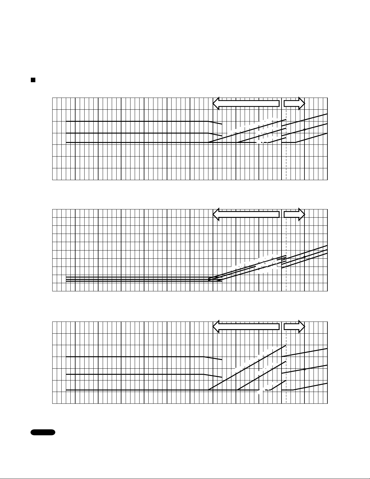
5. PERFORMANCE DATA
5-1. Temperature Charts
Indoor Unit KHS3082
Outdoor Unit CH3082
• Check each performance value in test-run mode. Electrical performance values represent a combined indoor/outdoor value.
NOTE
Cooling Characteristics (RH : 46%, Indoor fan speed : High fan) (60Hz, 230V)
(1) Low pressure performance chart
(2) Operating current performance chart
(3) Indoor discharge air performance chart
-4
(-20)
5
(-15)
14
(-10)
23
(-5)
32
(0)
41
(5)
50
(10)
59
(15)
68
(20)
77
(25)
86
(30)
95
(35)
104
(40)
Outdoor inlet air D.B. temp.°F(°C)
Outdoor inlet air D.B. temp.°F(°C)
Outdoor inlet air D.B. temp.°F(°C)
Operating current (A)
Indoor discharge air temperature °F(
°C)
Low pressure at wide tube service valve
psig(MPaG)
-4
(-20)
5
(-15)
14
(-10)
23
(-5)
32
(0)
41
(5)
50
(10)
59
(15)
68
(20)
77
(25)
86
(30)
95
(35)
104
(40)
-4
(-20)
5
(-15)
14
(-10)
23
(-5)
32
(0)
41
(5)
50
(10)
59
(15)
68
(20)
77
(25)
86
(30)
95
(35)
104
(40)
57.2 (14)
64.4 (18)
60.8 (16)
53.6 (12)
50.0 (10)
46.4 (8)
42.8 (6)
10
12
14
16
18
20
22
24
26
28
104
(0.7)
117
(0.8)
131
(0.9)
145
(1.0)
159
(1.1)
174
(1.2)
Hi FanLo fan
Hi FanLo fan
Hi FanLo fan
Indoor Air Temp.86
°
F (30
°
C)
80
°
F (27
°
C)
75
°
F (24
°
C)
Indoor Air Temp.86
°
F (30°
C)
80
°
F (27
°
C)
75
°
F (24
°
C)
Indoor Air Tem
p.86
°F (30
°
C)
80
°
F (27
°
C)
75
°
F (24
°
C)
Indoor Air Temp.86°F (30°C)
80°F (27°C)
75°F (24°C)
Indoor Air Temp.86°F (30°C)
80°F (27°C)
75°F (24°C)
Indoor Air Tem
p.86°F (30°C
)
80°F (27°C
)
75°F (24°C
)
19
Indoor Unit KHS3082
Outdoor Unit CH3082
• Check each performance value in test-run mode. Electrical performance values represent a combined indoor/outdoor value.
• Overload prevention operates to protect the air conditioner when outdoor ambient temperature becomes extremely high in
heating mode. (Refer to "7-2. Overload prevention during heating.")
NOTE
Indoor discharge air temperature °F(°C)
23
(–5)
32
(0)
41
(5)
50
(10)
59
(15)
68
(20)
77
(25)
Outdoor inlet air D.B. temp. °F(°C)
Outdoor inlet air D.B. temp. °F(°C)
23
(–5)
32
(0)
41
(5)
19
18
17
16
15
14
13
50
(10)
59
(15)
68
(20)
77
(25)
Operating current (A)
23
(–5)
32
(0)
41
(5)
50
(10)
131(55)
122(50)
113(45)
104(40)
95(35)
86(30)
59
(15)
68
(20)
77
(25)
Outdoor inlet air D.B. temp. °F(°C)
High pressure at wide tube service valve
psig (MPaG)
494
(3.4)
421
(2.9)
348
(2.4)
275
(1.9)
Heating Characteristics (RH : 46%, Indoor fan speed : High fan) (60Hz, 230V)
(1) High pressure performance chart
(2) Operating current performance chart
(3) Indoor discharge air performance chart
63
°
F (
17
°
C)
Indoor air temp.73
°
F (23
°
C)
70
°
F (
21
°
C)
63
°F (
17
°C)
Indoor air temp.73
°F (23°C)
70
°F (
21
°C)
63
°
F (
17
°
C)
Indoor air temp.73
°F (23
°C)
70
°F (
21
°C)
63
°F (
17
°C)
Indoor air temp.73
°F (23°C)
70
°F (
21
°C)
63
°
F (
17
°
C)
Indoor air tem
p.73
°
F (23
°
C)
70
°
F (
21
°
C)
63
°F (
17
°C)
Indoor air tem
p.73
°F (23°C)
70
°F (
21
°C)
20
Indoor Unit KHS3682
Outdoor Unit CH3682
Cooling Characteristics (RH : 46%, Indoor fan speed : High fan) (60Hz, 230V)
(1) Low pressure performance chart
(2) Operating current performance chart
(3) Indoor discharge air performance chart
-4
(-20)
5
(-15)
14
(-10)
23
(-5)
32
(0)
41
(5)
50
(10)
59
(15)
68
(20)
77
(25)
86
(30)
95
(35)
104
(40)
Outdoor inlet air D.B. temp.°F(°C)
Outdoor inlet air D.B. temp.°F(°C)
Outdoor inlet air D.B. temp.°F(°C)
Operating current (A)
Indoor discharge air temperature °F(
°C)
Low pressure at wide tube service valve
psig(MPaG)
-4
(-20)
5
(-15)
14
(-10)
23
(-5)
32
(0)
41
(5)
50
(10)
59
(15)
68
(20)
77
(25)
86
(30)
95
(35)
104
(40)
-4
(-20)
5
(-15)
14
(-10)
23
(-5)
32
(0)
41
(5)
50
(10)
59
(15)
68
(20)
77
(25)
86
(30)
95
(35)
104
(40)
• Check each performance value in test-run mode. Electrical performance values represent a combined indoor/outdoor value.
NOTE
57.2 (14)
60.8 (16)
64.4 (18)
53.6 (12)
50.0 (10)
46.4 (8)
42.8 (6)
10
12
14
16
18
20
22
24
26
28
104
(0.7)
117
(0.8)
131
(0.9)
145
(1.0)
159
(1.1)
174
(1.2)
Hi FanLo fan
Hi FanLo fan
Hi FanLo fan
Indoor Air Temp.86
°
F (30
°
C)
80
°
F (27
°C)
75
°
F (24
°
C)
Indoor Air Temp.86
°
F (30
°
C)
80
°
F (27
°
C)
75
°
F (24
°
C)
Indoor Air Temp.86
°
F (30
°C)
80
°
F (27°
C)
75
°
F (24
°
C)
Indoor Air Temp.86°F (30°C)
80°F (27°C
)
75°F (24°C)
Indoor Air Temp.86°F (30°C)
80°F (27°C)
75°F (24°C)
Indoor Air Temp.86°F (30°C)
80°F (27°C)
75°F (24°C)
21
Indoor Unit KHS3682
Outdoor Unit CH3682
Indoor discharge air temperature °F(°C)
23
(–5)
32
(0)
41
(5)
50
(10)
59
(15)
68
(20)
77
(25)
Outdoor inlet air D.B. temp. °F(°C)
Outdoor inlet air D.B. temp. °F(°C)
23
(–5)
32
(0)
41
(5)
22
21
20
19
18
17
16
50
(10)
59
(15)
68
(20)
77
(25)
Operating current (A)
23
(–5)
32
(0)
41
(5)
50
(10)
131(55)
122(50)
113(45)
104(40)
95(35)
86(30)
59
(15)
68
(20)
77
(25)
Outdoor inlet air D.B. temp. °F(°C)
High pressure at wide tube service valve
psig (MPaG)
494
(3.4)
421
(2.9)
348
(2.4)
275
(1.9)
• Check each performance value in test-run mode. Electrical performance values represent a combined indoor/outdoor value.
• Overload prevention operates to protect the air conditioner when outdoor ambient temperature becomes extremely high in
heating mode. (Refer to "7-2. Overload prevention during heating.")
NOTE
Heating Characteristics (RH : 46%, Indoor fan speed : High fan) (60Hz, 230V)
(1) High pressure performance chart
(2) Operating current performance chart
(3) Indoor discharge air performance chart
70
°
F (
21
°C)
63
°
F (
17
°
C)
Indoor air temp.73
°
F (
23°
C)
70
°F (
21
°C)
63
°F (
17
°C)
Indoor air temp.73
°F (
23°C)
70
°
F (
21
°
C)
63
°
F (
17
°
C)
Indoor air temp.73
°
F (
23
°
C)
70
°F (
21
°C)
63
°F (
17
°C)
Indoor air temp.73
°F (
23°C)
70
°
F (
21
°
C)
63
°
F (
17
°
C)
Indoor air temp.73
°
F (
23°
C)
70
°F (
21
°C)
63
°F (
17
°C)
Indoor air temp.73
°F (
23°C)
22
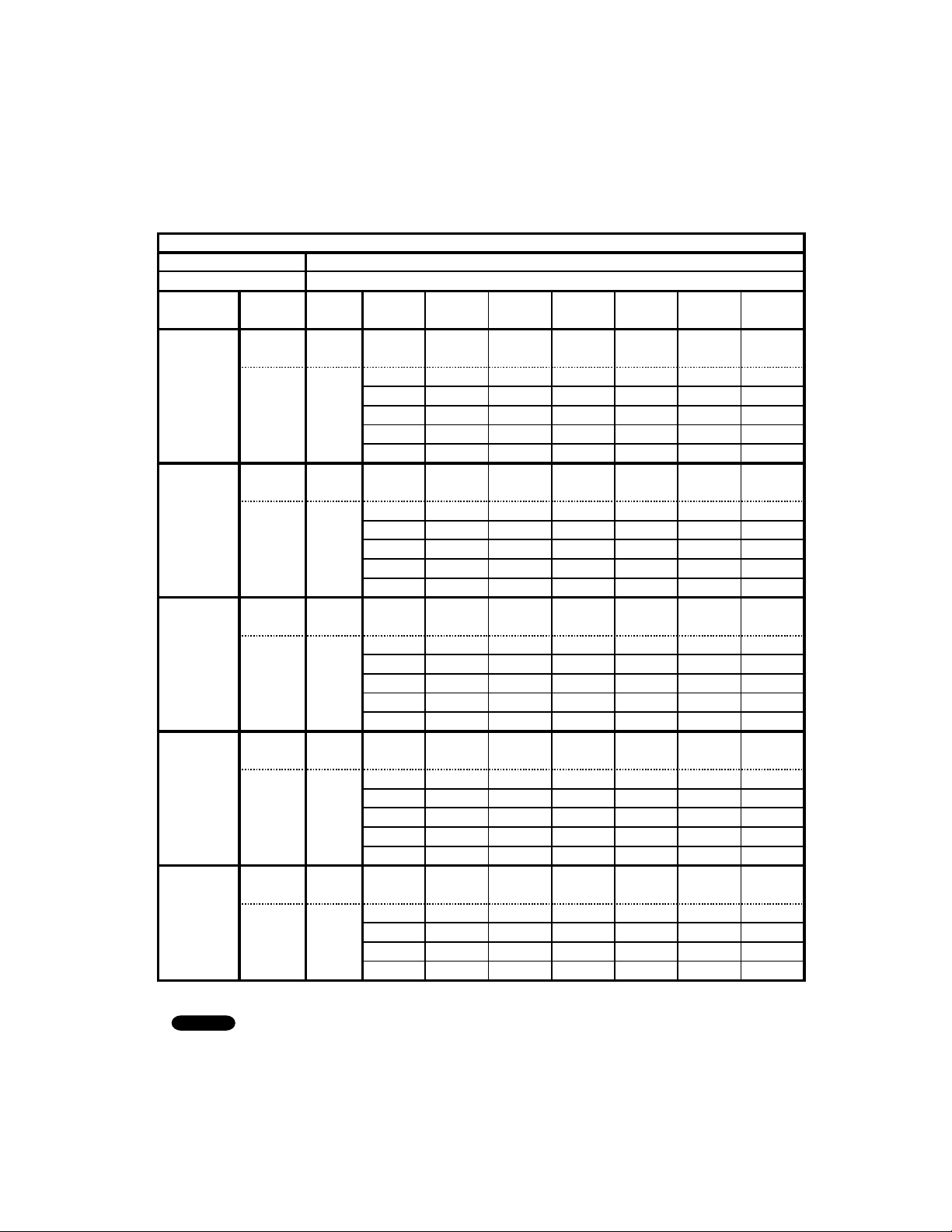
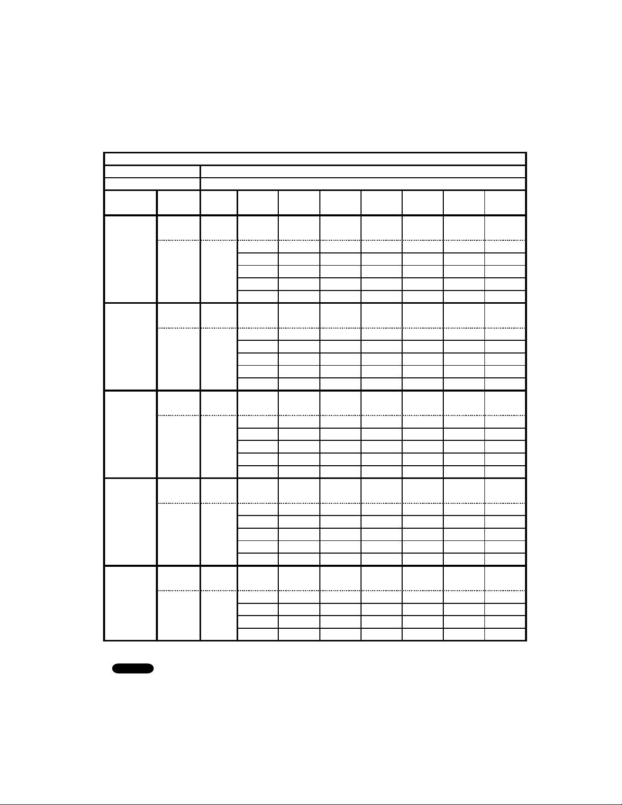
Indoor Unit : KHS3082
Outdoor Unit : CH3082
Power Supply : 230V Single Phase 60Hz
< Cooling Capacity (Low Ambient) >
5-2. Cooling Capacity
TC : Total Cooling Capacity (BTU/h) SHC : Sensible Heat Capacity (BTU/h)
1.
2. Above data represents the value when the operation frequency of a compressor is fixed.
Above data does not take Freeze Prevention Protection during cooling operation into account.
For this reason, the value may vary from the actual cooling characteristics.
NOTE
RATING CAPACITY: 30,600 BTU/h AIR FLOW RATE: 630CFM
INDOOR OUTDOOR
ENT. TEMP.
o
F (
o
C)AMBIENT TEMP.
o
F (
o
C)
W.B. D.B. 0515 25 35 45 55
(-17.8)(-15.0) (-9.4) (-3.9)(1.7) (7.2)(12.8)
TC 30,120 30,060 29,930 29,780 29,590 29,330 29,070
72 (22.2) SHC 21,150 21,150 21,020 20,900 20,780 20,660 20,530
59 76 (24.4) SHC 23,470 23,470 23,350 23,230 23,230 22,980 22,860
(15.0) 80 (26.7) SHC 25,920 25,920 25,790 25,790 25,670 25,430 25,300
84 (28.9) SHC 28,240 28,240 28,120 28,120 27,990 27,870 27,630
88 (31.1) SHC 30,120 30,060 29,930 29,780 29,590 29,330 29,070
TC 30,390 30,360 30,270 30,170 30,040 29,820 29,610
72 (22.2) SHC 17,720 17,720 17,600 17,600 17,480 17,360 17,360
63 76 (24.4) SHC 20,050 20,050 19,920 19,920 19,800 19,800 19,680
(17.2) 80 (26.7) SHC 22,490 22,490 22,370 22,370 22,370 22,250 22,120
84 (28.9) SHC 24,820 24,820 24,820 24,690 24,690 24,570 24,450
88 (31.1) SHC 27,140 27,140 27,140 27,020 27,020 26,890 26,770
TC 30,490 30,480 30,450 30,400 30,330 30,160 30,020
72 (22.2) SHC 14,180 14,180 14,180 14,180 14,180 14,050 14,050
67 76 (24.4) SHC 16,500 16,500 16,500 16,500 16,500 16,380 16,380
(19.4) 80 (26.7) SHC 19,070 18,940 18,940 18,940 18,940 18,820 18,820
84 (28.9) SHC 21,390 21,390 21,390 21,270 21,270 21,150 21,150
88 (31.1) SHC 23,710 23,710 23,710 23,710 23,590 23
,590 23,470
TC 30,370 30,380 30,410 30,430 30,420 30,310 30,250
72 (22.2) SHC 10,510 10,510 10,510 10,630 10,630 10,510 10,510
71 76 (24.4) SHC 12,950 12,950 12,950 12,950 12,950 12,830 12,830
(21.7) 80 (26.7) SHC 15,400 15,400 15,400 15,400 15,400 15,280 15,280
84 (28.9) SHC 17,720 17,720 17,720 17,720 17,720 17,720 17,600
88 (31.1) SHC 20,050 20,050 20,050 20,050 20,050 20,050 20,050
TC 30,030 30,080 30,170 30,240 30,310 30,250 30,270
75 76 (24.4) SHC 9,410 9,4109,410 9,5309,530 9,530 9,530
(23.9) 80 (26.7) SHC 11,850 11,850 11,850 11,970 11,970 11,970 11,970
84 (28.9) SHC 14,180 14,180 14,300 14,300 14,300 14,300 14,300
88 (31.1) SHC 16,500 16,620 16,620 16,620 16,620 16,620 16,620
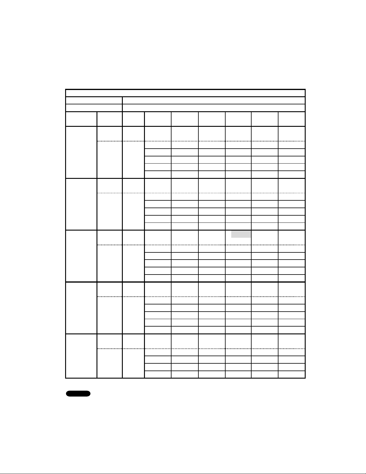
23
1.
Rating conditions (#)
: Indoor Unit Entering Air Temp. 80 °F (26.7 °C) D.B. / 67 °F (19.4 °C) W.B.
: Outdoor Ambient Temp. 95 °F (35 °C) D.B.
2.
3. Above data represents the value when the operation frequency of a compressor is fixed.
Above data does not take Freeze Prevention Protection during cooling operation into account.
For this reason, the value may vary from the actual cooling characteristics.
NOTE
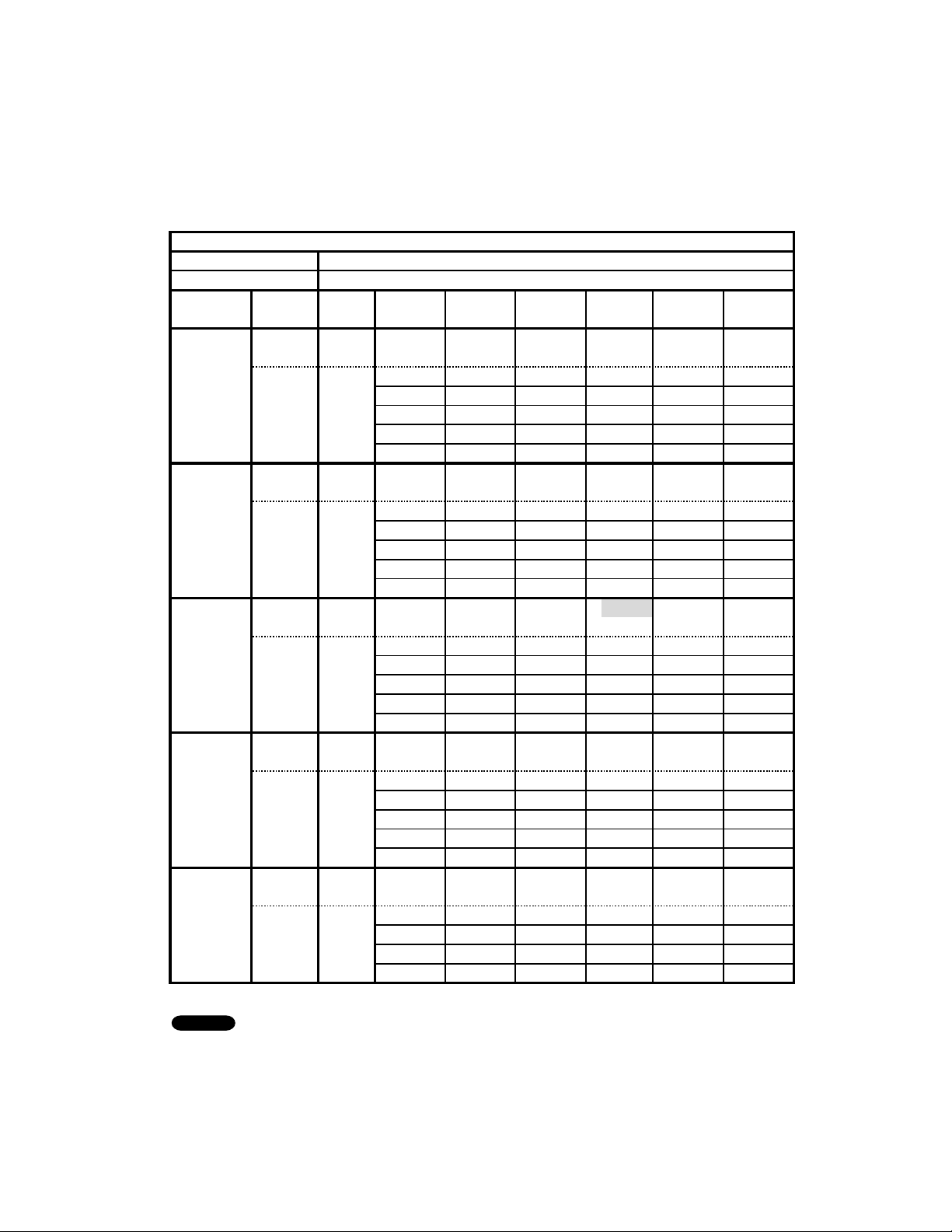
< Cooling Capacity >
TC : Total Cooling Capacity (BTU/h) SHC : Sensible Heat Capacity (BTU/h)
RATING CAPACITY: 30,600 BTU/hAIR FLOW RATE: 630 CFM
INDOOR OUTDOOR
ENT. TEMP.
o
F (
o
C) AMBIENT TEMP.
o
F (
o
C)
W.B. D.B. 65758595105 115
(18.3) (23.9) (29.4) (35.0) (40.6)(46.1)
TC 30,650 29,970 29,19028,600 24,890 17,310
72 (22.2) SHC 21,390 21,020 20,66020,290 18,330 14,660
59 76 (24.4) SHC 23,710 23,350 22,98022,610 20,66016,990
(15.0) 80 (26.7)SHC 26,280 25,790 25,43025,060 23,100 17,310
84 (28.9) SHC 28,610 28,240 27,75027,380 24,890 17,310
88 (31.1) SHC30,650 29,970 29,190 28,600 24,890 17,310
TC 31,580 30,910 30,16029,630 25,270 17,560
72 (22.2) SHC 18,330 17,970 17,600 17,360 15,150 11,730
6376 (24.4) SHC20,66020,29019,920 19,680 17,480 14,050
(17.2) 80 (26.7)SHC 23,100 22,740 22,370 22,120 20,050 16,500
84 (28.9) SHC25,43025,06024,690 24,450 22,370 17,560
88 (31.1) SHC27,75027,51027,020 26,770 24,690 17,560
TC 32,420 31,780 31,050#30,600 25,550 17,760
72 (22.2) SHC15,15014,79014,420 14,300 12,100 8,920
6776 (24.4) SHC17,48017,11016,870 16,620 14,420 11,240
(19.4) 80 (26.7)SHC 19,920 19,56019,310 19,070 16,870 13,690
84 (28.9) SHC22,25022,00021,640 21,390 19,190 16,010
88 (31.1) SHC24,57024,33023,96023,71021,51017,
760
TC 33,130 32,540 31,84031,490 25,710 17,880
72 (22.2) SHC11,73011,48011,120 11,000 8,670 5,860
71 76 (24.4) SHC14,05013,81013,440 13,320 11,120 8,310
(21.7) 80 (26.7)SHC 16,500 16,250 15,890 15,770 13,56010,750
84 (28.9) SHC18,82018,58018,330 18,210 15,890 13,070
88 (31.1) SHC21,15020,90020,66020,53018,21015,400
TC 33,630 33,090 32,43032,190 25,730 17,900
75 76 (24.4) SHC10,75010,51010,26010,1407,940 5,370
(23.9) 80 (26.7)SHC 13,200 12,950 12,710 12,590 10,380 7,820
84 (28.9) SHC15,52015,28015,030 15,030 12,710 10,140
88 (31.1) SHC17,84017,72017,480 17,36015,03012,590
24
Indoor Unit : KHS3682
Outdoor Unit : CH3682
Power Supply : 230V Single Phase 60Hz
< Cooling Capacity (Low Ambient) >
TC : Total Cooling Capacity (BTU/h) SHC : Sensible Heat Capacity (BTU/h)
1.
2. Above data represents the value when the operation frequency of a compressor is fixed.
Above data does not take Freeze Prevention Protection during cooling operation into account.
For this reason, the value may vary from the actual cooling characteristics.
NOTE
RATING CAPACITY: 34,000BTU/h AIR FLOW RATE: 630CFM
INDOOR OUTDOOR
ENT. TEMP.
o
F (
o
C) AMBIENT TEMP.
o
F (
o
C)
W.B. D.B. 0515 25 35 45 55
(-17.8) (-15.0) (-9.4) (-3.9) (1.7)(7.2) (12.8)
TC 30,900 30,870 30,800 30,710 30,590 30,400 30,210
72 (22.2) SHC 21,510 21,510 21,510 21,510 21,390 21,270 21,150
59 76 (24.4) SHC 23,960 23,840 23,840 23,840 23,710 23,590 23,470
(15.0) 80 (26.7) SHC 26,400 26,400 26,280 26,280 26,160 26,040 25,920
84 (28.9) SHC 28,730 28,730 28,610 28,610 28,480 28,480 28,360
88 (31.1) SHC 30,900 30,870 30,800 30,710 30,590 30,400 30,210
TC 31,010 31,010 30,990 30,950 30,890 30,750 30,620
72 (22.2) SHC 17,970 17,970 17,970 17,970 17,970 17,840 17,840
63 76 (24.4) SHC 20,410 20,410 20,290 20,290 20,290 20,170 20,170
(17.2) 80 (26.7) SHC 22,860 22,860 22,740 22,740 22,740 22,610 22,610
84 (28.9) SHC 25,180 25,180 25,180 25,060 25,060 25,060 24,940
88 (31.1) SHC 27,510 27,510 27,510 27,510 27,380 27,380 27,260
TC 30,910 30,940 30,980 31,000 31,010 30,930 30,880
72 (22.2) SHC 14,420 14,420 14,420 14,420 14,420 14,420 14,420
67 76 (24.4) SHC 16,740 16,740 16,740 16,740 16,740 16,740 16,740
(19.4) 80 (26.7) SHC 19,190 19,190 19,190 19,190 19,190 19,190 19,190
84 (28.9) SHC 21,510 21,510 21,640 21,640 21,640 21,510 21,510
88 (31.1) SHC 23,840 23,960 23,960 23,960 23,960 23,960 23,840
TC 30,570 30,620 30,730 30,820 30,910 30,900 30,930
72 (22.2) SHC 10,630 10,630 10
,750 10,750 10,750 10,750 10,750
71 76 (24.4) SHC 12,950 12,950 13,070 13,070 13,070 13,070 13,070
(21.7) 80 (26.7) SHC 15,400 15,400 15,520 15,520 15,520 15,520 15,520
84 (28.9) SHC 17,720 17,840 17,840 17,840 17,970 17,970 17,970
88 (31.1) SHC 20,170 20,170 20,170 20,170 20,290 20,290 20,290
TC 30,010 30,090 30,260 30,430 30,590 30,650 30,770
75 76 (24.4) SHC 9,410 9,4109,530 9,530 9,650 9,6509,650
(23.9) 80 (26.7) SHC 11,850 11,850 11,970 11,970 12,100 12,100 12,100
84 (28.9) SHC 14,180 14,180 14,300 14,300 14,420 14,420 14,420
88 (31.1) SHC 16,500 16,620 16,620 16,740 16,740 16,740 16,870
25
Indoor Unit : KHS3682
Outdoor Unit : CH3682
Power Supply : 230V Single Phase 60Hz
< Cooling Capacity >
TC : Total Cooling Capacity (BTU/h) SHC : Sensible Heat Capacity (BTU/h)
1.
Rating conditions (#)
: Indoor Unit Entering Air Temp. 80 °F (26.7 °C) D.B. / 67 °F (19.4 °C) W.B.
: Outdoor Ambient Temp. 95 °F (35 °C) D.B.
2.
3. Above data represents the value when the operation frequency of a compressor is fixed.
Above data does not take Freeze Prevention Protection during cooling operation into account.
For this reason, the value may vary from the actual cooling characteristics.
NOTE
RATING CAPACITY: 34,000BTU/h AIR FLOW RATE: 630CFM
INDOOR OUTDOOR
ENT. TEMP.
o
F (
o
C) AMBIENT TEMP.
o
F (
o
C)
W.B. D.B. 65 75 85 95 105 115
(18.3) (23.9) (29.4) (35.0)(40.6)(46.1)
TC 34,170 33,480 32,690 32,110 24,650 16,770
72 (22.2) SHC 23,470 23,100 22,610 22,25018,21014,420
5976(24.4)SHC 25,790 25,430 24,940 24,570 20,530 16,740
(15.0)80(26.7)SHC 28,240 27,870 27,380 27,020 22,980 16,770
84 (28.9) SHC 30,560 30,200 29,710 29,460 24,65016,770
88 (31.1) SHC 33,010 32,520 32,030 31,790 24,65016,770
TC 35,010 34,360 33,600 33,100 24,85016,910
72 (22.2) SHC 20,170 19,800 19,310 19,070 15,030 11,480
63 76 (24.4) SHC 22,490 22,120 21,760 21,390 17,360 13,810
(17.2) 80 (26.7) SHC 24,940 24,570 24,200 23,840 19,800 16,250
84 (28.9) SHC 27,260 26,890 26,530 26,280 22,120 16,910
88 (31.1) SHC 29,580 29,220 28,85028,610 24,45016,910
TC 35,720 35,120 34,400 #34,000 24,930 16,970
72 (22.2) SHC 16,620 16,380 16,010 15,890 11,730 8,670
67 76 (24.4) SHC 19,070 18,700 18,330 18,210 14,180 11,000
(19.4) 80 (26.7) SHC 21,510 21,15020,90020,660 16,620 13,440
84 (28.9) SHC 23,840 23,590 23,230 22,980 18,940 15,770
88 (31.1) SHC 26,160 25,920 25,55025,300 21,270 16,970
TC 36,270 35,710 35,040 34,780 24,870 16,95
0
72 (22.2) SHC 13,070 12,830 12,460 12,340 8,4305,610
71 76 (24.4) SHC15,400 15,15014,79014,790 10,7507,940
(21.7) 80 (26.7) SHC 17,840 17,600 17,360 17,230 13,200 10,380
84 (28.9) SHC 20,170 19,920 19,680 19,560 15,520 12,710
88 (31.1) SHC 22,490 22,25022,00021,880 17,840 15,030
TC 36,560 36,070 35,45034,630 24,680 16,830
75 76 (24.4) SHC 11,850 11,610 11,360 11,120 7,570 5,130
(23.9) 80 (26.7) SHC 14,300 14,05013,81013,560 10,020 7,570
84 (28.9) SHC 16,620 16,500 16,25015,890 12,340 9,900
88 (31.1) SHC 18,940 18,820 18,580 18,210 14,660 12,220
26
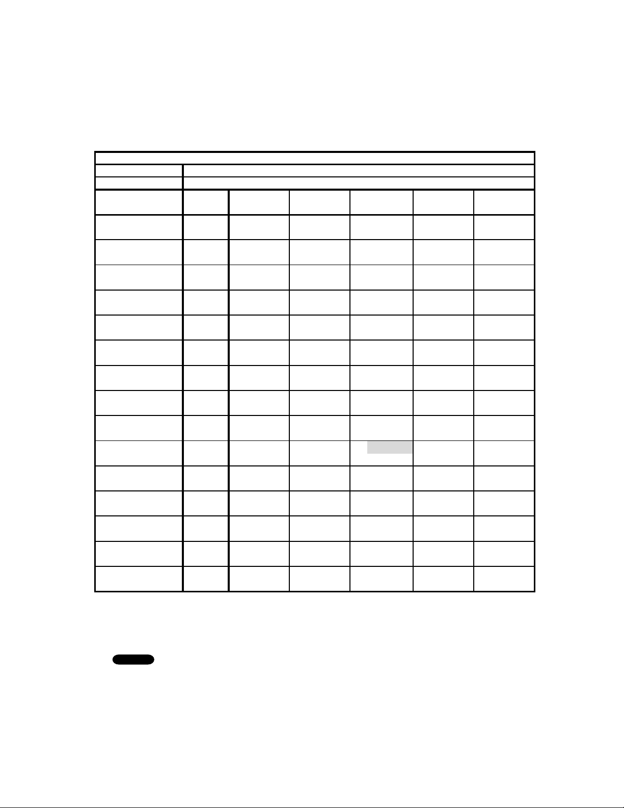
Indoor Unit : KHS3082
Outdoor Unit : CH3082
Power Supply : 230V Single Phase 60Hz
< Heating Capacity >
5-3. Heating Capacity
TH : Total Heating Capacity (BTU/h)
1.
Rating conditions (#)
: Indoor Unit Entering Air Temp. 70 °F (21.1 °C) D.B.
: Outdoor Ambient Temp. 47 °F (8.3 °C) D.B. / 43 °F (6.1 °C) W.B.
2.
3. Above data represents the value when the operation frequency of a compressor is fixed.
Above data does not take Defrost Operation, Overload Prevention Protection, and/or Cold Air
Prevention Protection during heating operation into account. For this reason, the value may vary
from the actual heating characteristics.
NOTE
RATING CAPACITY: 33,000BTU/h AIR FLOW RATE: 671 CFM
OUTDOOR INDOOR
ENT. TEMP.
o
F (
o
C)AMBIENT TEMP.
o
F (
o
C)
W.B. 60 65 70 75 80
(15.6) (18.3) (21.1) (23.9) (26.7)
0(-17.8) TH 18,060 18,120 18,170 18,210 18,240
3(-16.1) TH 18,670 18,730 18,780 18,820 18,850
8(-13.3) TH 20,120 20,190 20,240 20,280 20,320
13 (-10.6) TH 21,640 21,710 21,770 21,810 21,840
18 (-7.8) TH 23,320 23,390 23,450 23,500 23,530
23 (-5.0) TH 25,100 25,170 25,230 25,280 25,310
28 (-2.2) TH 26,960 27,030 27,090 27,140 27,160
33 (0.6)TH 28,900 28,970 29,030 29,070 29,090
38 (3.3)TH 30,830 30,900 30,950 30,990 30,500
43 (6.1)TH 32,880 32,950 #33,000 33,030 30,830
48 (8.9)TH 34,980 35,050 35,090 35,120 31,060
53 (11.7) TH 37,120 37,180 37,220 35,460 31,180
58 (14.4) TH 39,210 39,260 39,280 35,480 31,180
63 (17.2) TH 41,380 41,410 40,090 35,340 31,050
65 (18.3) TH 42,230 42,260 39,980 35,250 30,960
27
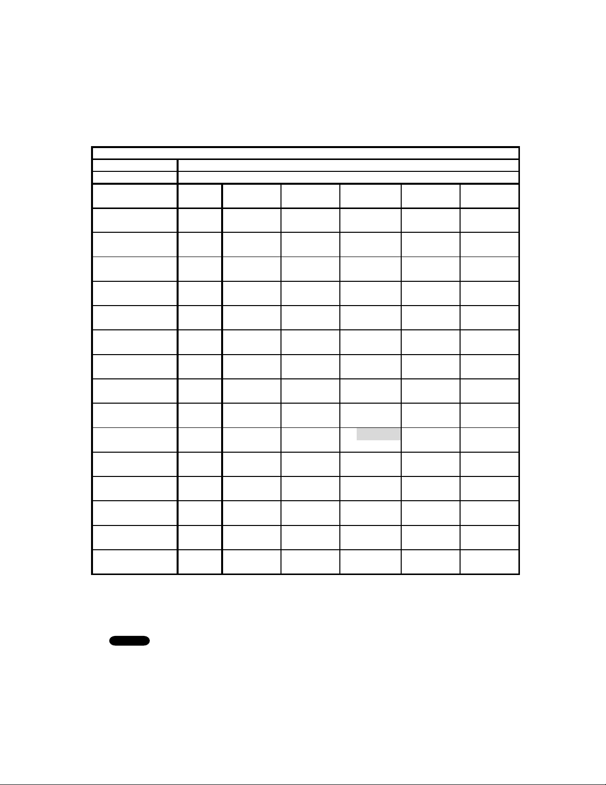
Indoor Unit : KHS3682
Outdoor Unit : CH3682
Power Supply : 230V Single Phase 60Hz
< Heating Capacity >
TH : Total Heating Capacity (BTU/h)
1.
Rating conditions (#)
: Indoor Unit Entering Air Temp. 70 °F (21.1 °C) D.B.
: Outdoor Ambient Temp. 47 °F (8.3 °C) D.B. / 43 °F (6.1 °C) W.B.
2.
3. Above data represents the value when the operation frequency of a compressor is fixed.
Above data does not take Defrost Operation, Overload Prevention Protection, and/or Cold Air
Prevention Protection during heating operation into account. For this reason, the value may vary
from the actual heating characteristics.
NOTE
RATING CAPACITY: 36,000BTU/h AIR FLOW RATE: 671 CFM
OUTDOORINDOOR
ENT. TEMP.
o
F (
o
C)AMBIENT TEMP.
o
F (
o
C)
W.B. 60 65 70 75 80
(15.6) (18.3) (21.1) (23.9) (26.7)
0 (-17.8) TH 19,760 19,860 19,940 20,010 20,080
3 (-16.1) TH 20,420 20,510 20,600 20,670 20,740
8 (-13.3) TH 21,990 22,090 22,180 22,260 22,330
13 (-10.6) TH 23,630 23,730 23,830 23,920 23,990
18 (-7.8)TH25,44025,560 25,660 25,750 25,820
23 (-5.0)TH27,36027,480 27,590 27,680 27,140
28 (-2.2)TH29,37029,490 29,600 29,700 27,580
33 (0.6)TH31,46031,590 31,700 31,560 27,940
38 (3.3)TH33,54033,670 33,780 31,900 28,210
43 (6.1)TH35,76035,890 # 36,000 32,150 28,410
48 (8.9)TH38,03038,160 36,450 32,300 28,520
53 (11.7) TH 40,340 40,460 36,500 32,330 28,530
58 (14.4) TH 42,580 41,040 36,420 32,230 28,430
63 (17.2) TH 44,920 40,770 36,160 32,000 28,210
65 (18.3) TH 45,520 40,610 36,020 31,870 28,090
28
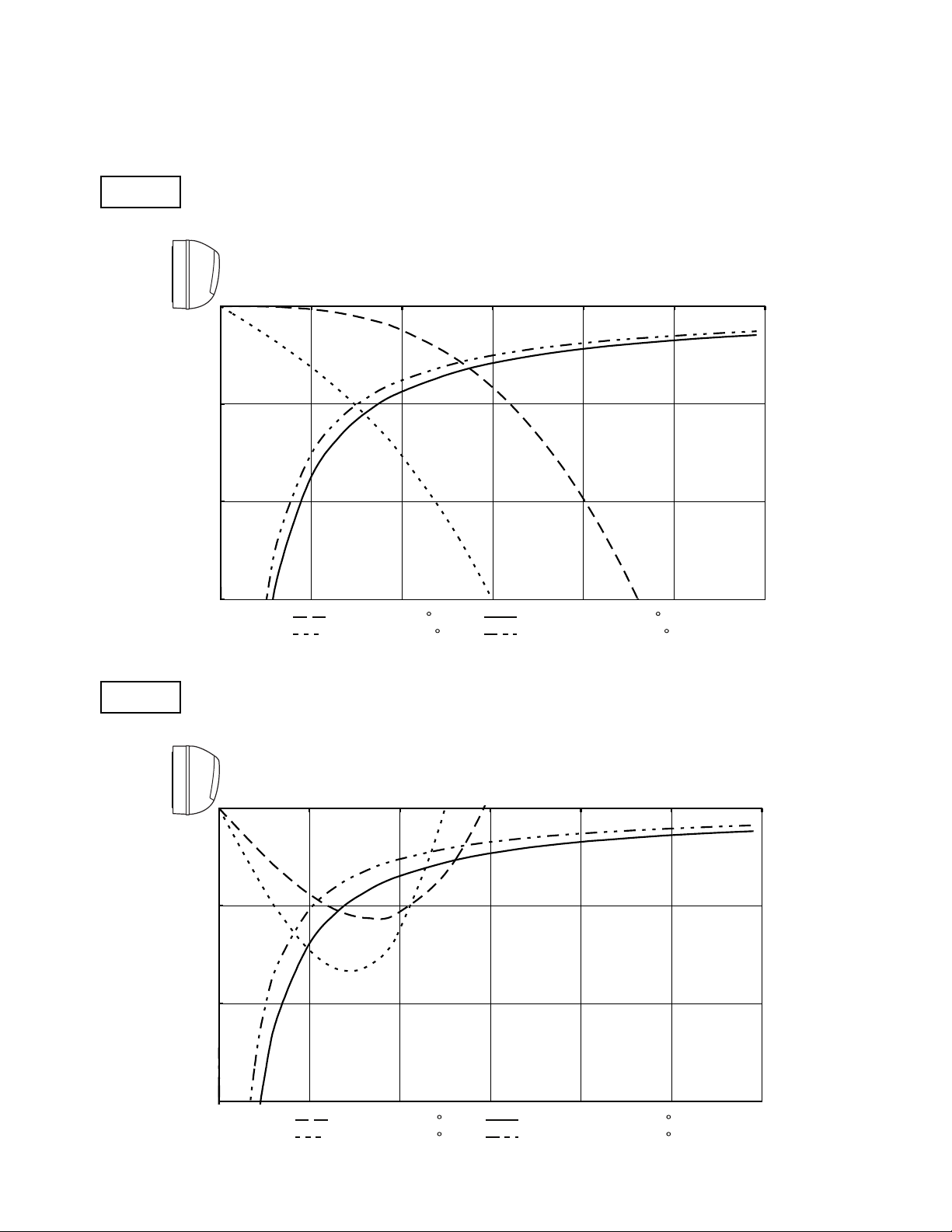
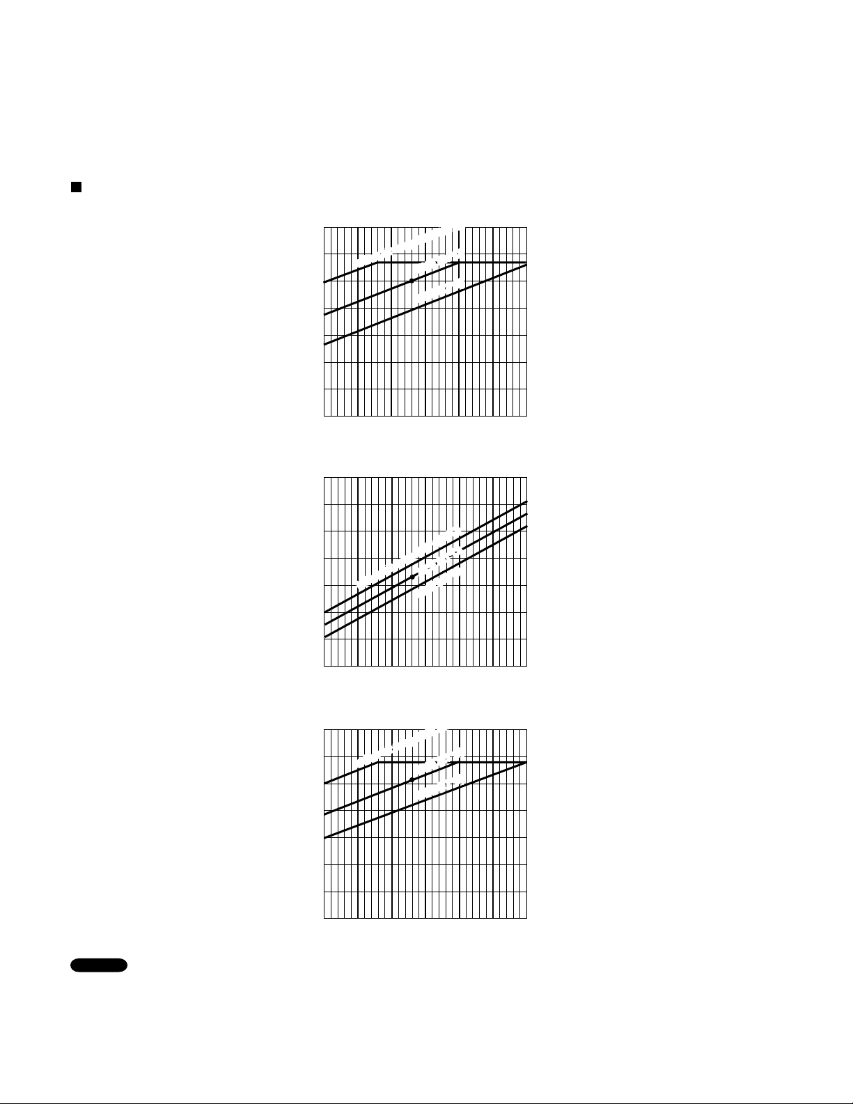
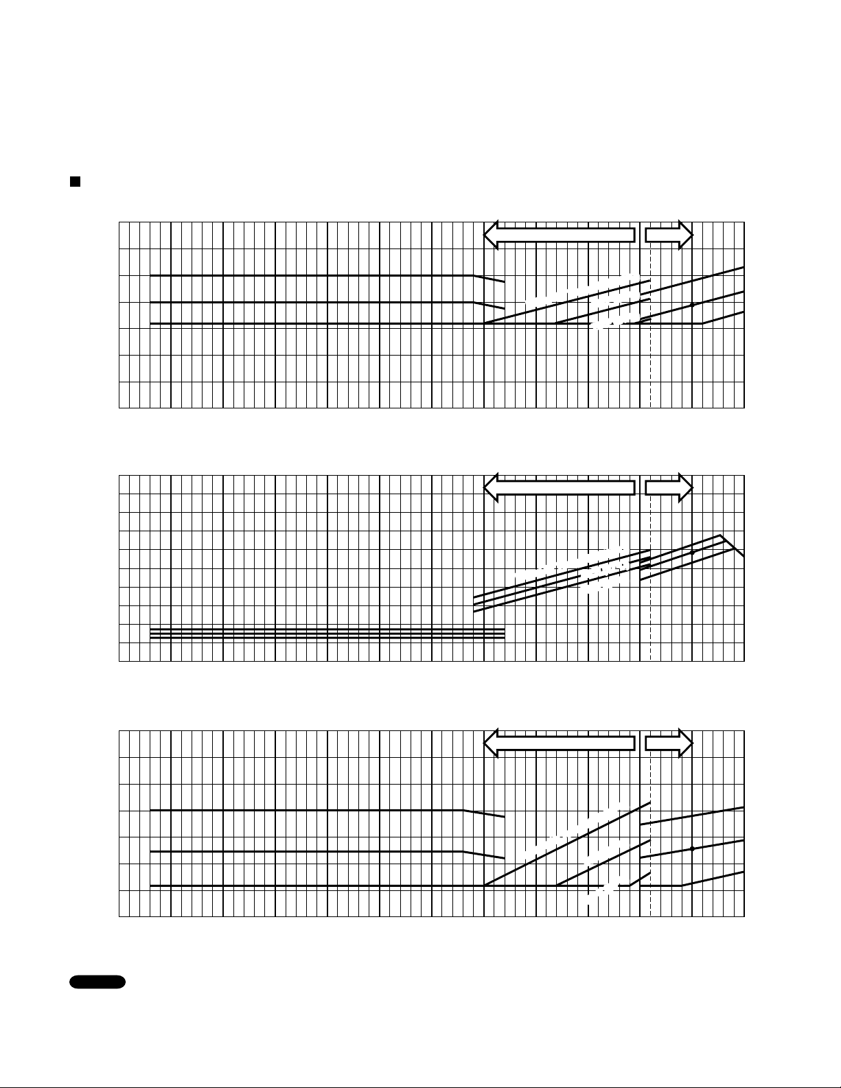
Horizontal distance (ft.)
Axis air velocity (ft./sec.)
Vertical distance (ft.)
Room air temp. :70°F (21.1°C)
Fan speed : High
Heating
Horizontal distance (ft.)
Axis air velocity (ft./sec.)
Vertical distance (ft.)
Room air temp. : 80°F (26.7°C)
Fan speed : High
Cooling
: Flap angle 0 , : Axis air velocity 0
: Flap angle 30 , : Axis air velocity 30
: Flap angle 45 , : Axis air velocity 45
: Flap angle 60 , : Axis air velocity 60
5-4. Air Throw Distance Charts
Indoor Unit KHS3082
0
5
10
15
0 5 10 15 20 25 30
0
5
10
15
0 5 10 15 20 25 30
29
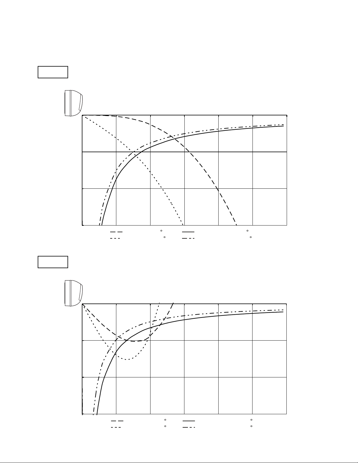
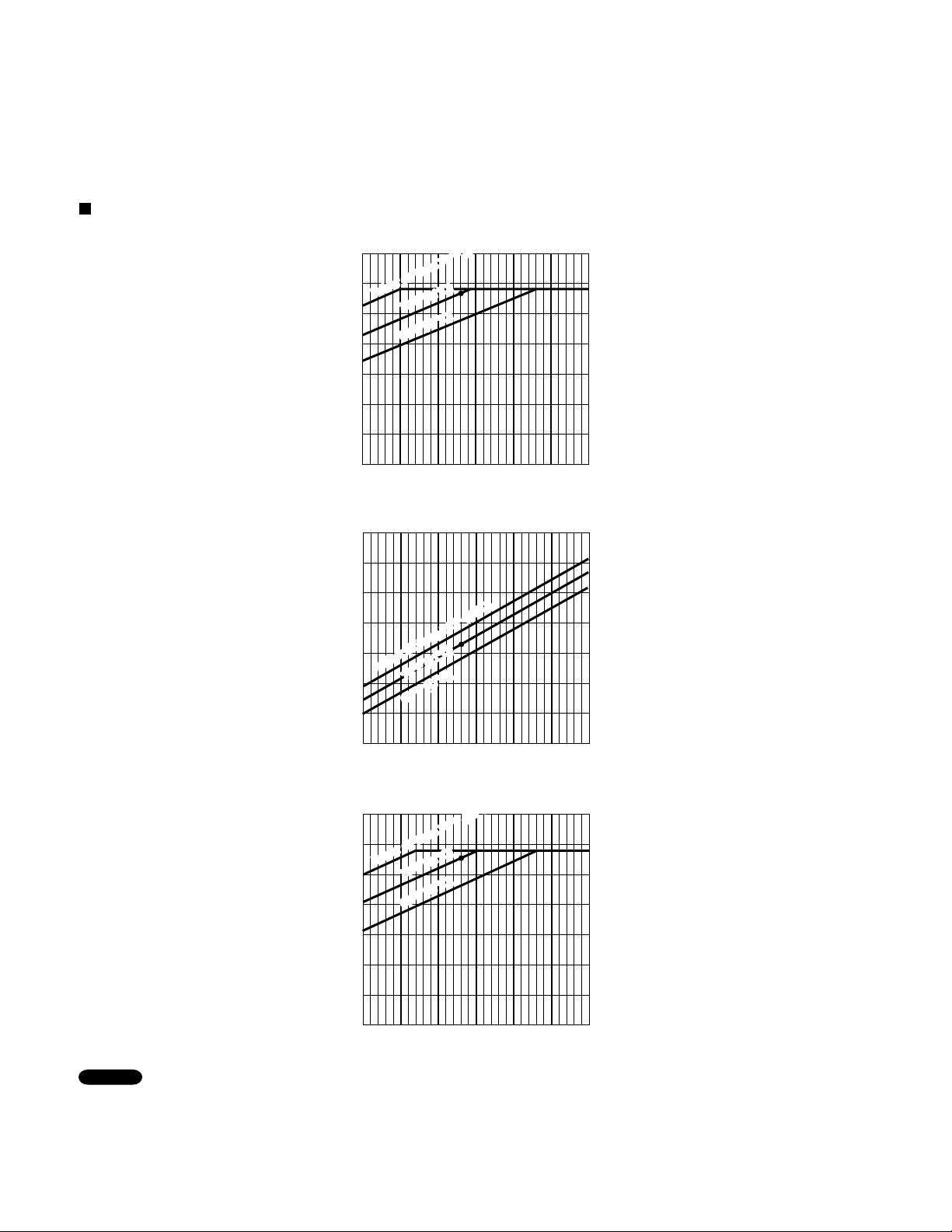
Horizontal distance (ft.)
Axis air velocity (ft./sec.)
Vertical distance (ft.)
Room air temp. :70°F (21.1°C)
Fan speed : High
Heating
Horizontal distance (ft.)
Axis air velocity (ft./sec.)
Vertical distance (ft.)
Room air temp. :80
°F
(26.7
°C
)
Fan speed : High
Cooling
: Flap angle 0 , : Axis air velocity 0
: Flap angle 30 , : Axis air velocity 30
: Flap angle 45 , : Axis air velocity 45
: Flap angle 60 , : Axis air velocity 60
Indoor Unit KHS3682
0
5
10
15
0 5 10 15 20 25 30
0
5
10
15
0 5 10 15 20 25 30
30
 Loading...