


Digital Video Recorder
with Multiplexer Function
DSR-3016 DSR-3009
Instruction Manual
Manuel d’instructions
Manual de Instrucciones
English GB
Français F
Español E
DSR-3016 |
DSR-3009 |
About this manual
•Before installing and using this unit, please read this manual carefully. Be sure to keep it handy for later reference.
•This manual gives basic connections and operating instructions for 2 models.
À propos de ce manuel
•Avant d’installer et d’utiliser cet appareil, veuillez lire ce manuel attentivement. Assurez-vous de le garder à portée de la main pour référence ultérieure.
•Ce manuel couvre les instructions de branchement et d’utilisation de base pour deux modèles.
Acerca de este manual
•Antes de instalar y usar este aparato, lea detenidamente este manual. Asegúrese de guardarlo a mano para futuras referencias.
•Este manual le indica las conexiones básicas y las instrucciones de funcionamiento de dos modelos.
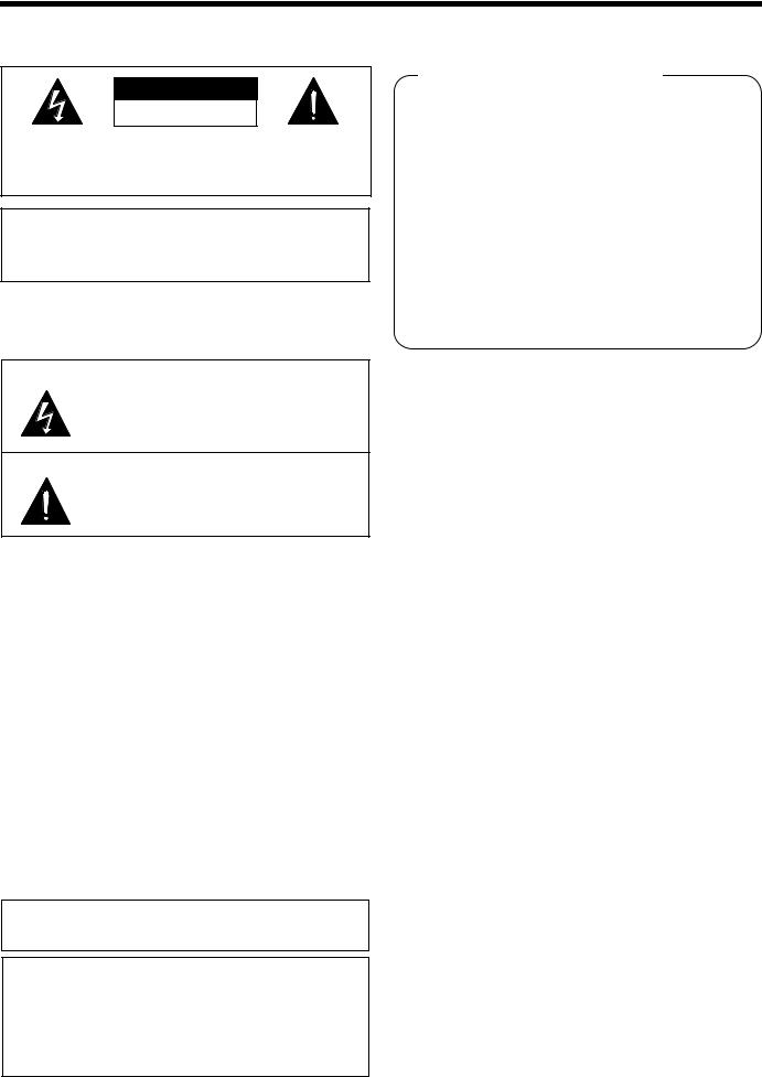
PRECAUTION
CAUTION
RISK OF ELECTRIC SHOCK
DO NOT OPEN
CAUTION: TO REDUCE THE RISK OF ELECTRIC SHOCK, DO NOT REMOVE COVER (OR BACK).
NO USER-SERVICEABLE PARTS INSIDE.
REFER SERVICING TO QUALIFIED SERVICE PERSONNEL.
WARNING: To reduce the risk of fire or electric shock, do not expose this appliance to rain or moisture.
CAUTION: Changes or modifications not expressly approved by the manufacturer may void the user’s authority to operate this equipment.
The lightning flash with arrowhead symbol, within an equilateral triangle, is intended to alert the user to the presence of uninsulated “dangerous voltage” within the product’s enclosure that may be of sufficient magnitude to constitute a risk of electric shock to persons.
The exclamation point within an equilateral triangle is intended to alert the user to the presence of important operating and maintenance (servicing) instructions in the literature accompanying the product.
This equipment has been tested and found to comply with the limits for a Class B digital device, pursuant to part 15 of the FCC Rules. These limits are designed to provide reasonable protection against harmful interference in a residential installation. This equipment generated, uses and can radiate radio frequency energy and, if not installed and used in accordance with the instructions, may cause harmful interference to radio communications. However, there is no guarantee that interference will not occur in a particular installation. If this equipment does cause harmful interference radio or television reception, which can be determined by turning the equipment off and on, the user is encouraged to try to correct the interference by one or more of the following measures:
•Reorient or relocate the receiving antenna.
•Increase the separation between the equipment and receiver.
•Connect the equipment into an outlet on a circuit different from that to which the receiver is connected.
•Consult the dealer or an experienced radio/TV technician for help.
For the customers in Canada
Declaration of Conformity
Model Number |
: DSR-3016, DSR-3009 |
Trade Name |
: SANYO |
Responsible party |
: SANYO FISHER COMPANY |
Address |
: 21605 Plummer Street, |
|
Chatsworth, California 91311 |
Telephone No. |
: (818) 998-7322 |
•This device complies with Part 15 of the FCC Rules. Operation is subject to the following two conditions:
(1)this device may not cause harmful interference, and
(2)this device must accept any interference received, including interference that may cause undesired operation.
Location
For safe operation and satisfactory performance of your unit, keep the following in mind when selecting a place for its installation:
•Shield it from direct sunlight and keep it away from sources of intense heat.
•Avoid dusty or humid places.
•Avoid places with insufficient ventilation for proper heat dissipation. Do not block the ventilation holes at the top and bottom of the unit. Do not place the unit on a carpet because this will block the ventilation holes.
•Install the unit in a horizontal position only.
•Avoid locations subject to strong vibrations.
•Avoid moving the unit between cold and hot locations.
•Do not place the unit directly on top of a monitor TV, as this may cause playback or recording problems.
Avoiding Electrical Shock and Fire
•Do not handle the power cord with wet hands.
•Do not pull on the power cord when disconnecting it from an AC wall outlet. Grasp it by the plug.
•If any liquid is spilled on the unit, unplug the power cord immediately and have the unit inspected at a factory-authorised service centre.
•Do not place anything directly on top of this unit.
SERVICE
This class B digital apparatus complies with Canadian ICES-003.
CAUTION
Danger of explosion if battery is incorrectly replaced. Replace only with the same or equivalent type recommended by the manufacturer.
Discard used batteries according to the manufacture’s instructions.
English
This unit is a precision instruments and if treated with care, will provide years of satisfactory performance. However, in the event of a problem, the owner is advised not to attempt to make repairs or open the cabinet. Servicing should always be referred to your dealer or Sanyo Authorized Service Centre.
1
CONTENTS
MAIN FEATURES. . . . . . . . . . . . . . . . . . . . . . . . . . . . . . . . . 3 ACCESSORIES . . . . . . . . . . . . . . . . . . . . . . . . . . . . . . . . . . 4 PART NAMES. . . . . . . . . . . . . . . . . . . . . . . . . . . . . . . . . . . . 5 CONNECTIONS . . . . . . . . . . . . . . . . . . . . . . . . . . . . . . . . . . 8
Basic connections (DSR-3016 model). . . . . . . . . . . . . . . . 8
Connecting high image quality (S-VHS) video
equipment . . . . . . . . . . . . . . . . . . . . . . . . . . . . . . . . . . . . . . 8 Connecting to an Amplifier . . . . . . . . . . . . . . . . . . . . . . . . 8 Digital series connections . . . . . . . . . . . . . . . . . . . . . . . . . 9 System control connections . . . . . . . . . . . . . . . . . . . . . . . 9 External alarm sensor setup . . . . . . . . . . . . . . . . . . . . . . . 10
Using as a monitor board during a motion sensor
alarm . . . . . . . . . . . . . . . . . . . . . . . . . . . . . . . . . . . . . . . . . . 10 Connecting a remote control circuit . . . . . . . . . . . . . . . . . 10
BUILT-IN HARD DISK . . . . . . . . . . . . . . . . . . . . . . . . . . . . . 11
Hard disk . . . . . . . . . . . . . . . . . . . . . . . . . . . . . . . . . . . . . . . 11 Operating display . . . . . . . . . . . . . . . . . . . . . . . . . . . . . . . . 13
VIEWING CAMERA IMAGES. . . . . . . . . . . . . . . . . . . . . . . . 14
Viewing a single-screen image . . . . . . . . . . . . . . . . . . . . . 14 Viewing multiple-screen images . . . . . . . . . . . . . . . . . . . . 16 Viewing automatically switching images . . . . . . . . . . . . . 17 Using two monitors for monitoring . . . . . . . . . . . . . . . . . . 19
RECORDING IMAGES IN THE NORMAL RECORDING AREA . . . . . . . . . . . . . . . . . . . . . . . . . . . . . . . . . . . . . . . . . . 20
Normal recording . . . . . . . . . . . . . . . . . . . . . . . . . . . . . . . . 20 Timer recording. . . . . . . . . . . . . . . . . . . . . . . . . . . . . . . . . . 21
RECORDING IMAGES IN THE ALARM RECORDING
AREA . . . . . . . . . . . . . . . . . . . . . . . . . . . . . . . . . . . . . . . . . . 22
Alarm recording . . . . . . . . . . . . . . . . . . . . . . . . . . . . . . . . . 22 Pre-alarm recording . . . . . . . . . . . . . . . . . . . . . . . . . . . . . . 23
PLAYING BACK RECORDED IMAGES . . . . . . . . . . . . . . . 24
Playback in a single screen . . . . . . . . . . . . . . . . . . . . . . . . 25 Playing back multiple-screen displays . . . . . . . . . . . . . . . 27
SEARCHING FOR RECORDED IMAGES . . . . . . . . . . . . . . 28 SAVING (COPYING) RECORDED IMAGES . . . . . . . . . . . . 35
A Copying images to the hard disk archive area. . . . . . . . . |
36 |
B Copying images from the archive area to a |
|
CompactFlash card or microdrive. . . . . . . . . . . . . . . . . . . |
37 |
C Copying images from the archive area to a DDS |
|
(DAT) drive or CD-R drive. . . . . . . . . . . . . . . . . . . . . . . . . . |
39 |
MENU FLOW CHART AND MENU OPERATIONS . . . . . . . 42
Menu Flow Chart . . . . . . . . . . . . . . . . . . . . . . . . . . . . . . . . . 42 Basic menu screen operations . . . . . . . . . . . . . . . . . . . . . 43 Operations while a sub-menu screen is displayed . . . . . 43 Entering numbers . . . . . . . . . . . . . . . . . . . . . . . . . . . . . . . . 43
INITIAL SET MENU . . . . . . . . . . . . . . . . . . . . . . . . . . . . . . . |
44 |
A LANGUAGE/CLOCK SET menu . . . . . . . . . . . . . . . . . . . . . |
44 |
B TIMER settings . . . . . . . . . . . . . . . . . . . . . . . . . . . . . . . . . . |
46 |
C HOLIDAY SET setting . . . . . . . . . . . . . . . . . . . . . . . . . . . . . |
48 |
D Automatic camera detection . . . . . . . . . . . . . . . . . . . . . . . |
49 |
RECORDING SETTING . . . . . . . . . . . . . . . . . . . . . . . . . . . . 50
A RECORDING AREA SET menu . . . . . . . . . . . . . . . . . . . . . 51 B RECORDING CONDITIONS SET menu . . . . . . . . . . . . . . . 52 C NORMAL REC MODE SET menu . . . . . . . . . . . . . . . . . . . . 54 D PROGRAM REC SET menu . . . . . . . . . . . . . . . . . . . . . . . . 55 E TIMER SET menu . . . . . . . . . . . . . . . . . . . . . . . . . . . . . . . . 56 F ALARM REC MODE SET menu . . . . . . . . . . . . . . . . . . . . . 59 G ALARM OPERATION SET menu . . . . . . . . . . . . . . . . . . . . 64
GENERAL SETTING . . . . . . . . . . . . . . . . . . . . . . . . . . . . . . 70
A DISPLAY SET menu . . . . . . . . . . . . . . . . . . . . . . . . . . . . . . |
71 |
B BUZZER SET setting. . . . . . . . . . . . . . . . . . . . . . . . . . . . . . |
72 |
C SECURITY LOCK SET setting . . . . . . . . . . . . . . . . . . . . . . |
73 |
D RS-232C/RS-485 SET SETTING . . . . . . . . . . . . . . . . . . . . . |
75 |
E HDD SET setting . . . . . . . . . . . . . . . . . . . . . . . . . . . . . . . . . |
76 |
F NETWORK SET SETTING. . . . . . . . . . . . . . . . . . . . . . . . . . |
77 |
SCREEN SETTING . . . . . . . . . . . . . . . . . . . . . . . . . . . . . . . |
80 |
A MULTI SCREEN setting . . . . . . . . . . . . . . . . . . . . . . . . . . . |
81 |
B SEQUENCE setting . . . . . . . . . . . . . . . . . . . . . . . . . . . . . . . |
82 |
C MASK settings . . . . . . . . . . . . . . . . . . . . . . . . . . . . . . . . . . |
85 |
POWER FAILURE/USED TIME DISPLAY . . . . . . . . . . . . . 87 SAVING MENU SETTING DETAILS . . . . . . . . . . . . . . . . . . 88
Saving to a CompactFlash card . . . . . . . . . . . . . . . . . . . . 88 Loading saved menu settings . . . . . . . . . . . . . . . . . . . . . . 89
INTERFACE SPECIFICATIONS . . . . . . . . . . . . . . . . . . . . . 91 SPECIFICATIONS . . . . . . . . . . . . . . . . . . . . . . . . . . . . . . . . 93
2 |
English |

MAIN FEATURES
This digital video recorder can be used to store images recorded by a monitoring camera onto its built-in hard disk.
This digital video recorder can display images that are being recorded by a camera in a split-screen (16, 9, 4), and it can also display images that have already been recorded in a split-screen.
The DSR-3009 model split-screen display is capable of 4-screen or 9-screen displays only.
•Equipped with a large-capacity 3.5-inch hard disk drive allowing recording and playback from the built-in hard disk
•Recording and playback of images can be carried out using digital signals from a multiplexer.
•Playback can be carried out at the same time as recording.
•Alarm recording tracks movements of suspicious individuals.
•Timer recording lets you record different sessions each day.
•Pre-alarm recording records the images immediately before an alarm.
•Audio recording and playback are also possible.
•Recorded images can be copied using CompactFlash cards.
•Includes a variety of search functions.
Alarm searching using an alarm event list or thumbnail alarm images
Time and date searches based on recording date and time
Motion sensor detecting by searching for the movement of a suspicious individual
•A zoom function allows images being monitored and played back to be enlarged for display.
•The image quality mode can be selected from five modes.
•High-speed switching for each field at maximum speed
•Single-screen, 4-screen, 9-screen and 16-screen display, camera images and video playback images can be displayed in the lower-right corner of the screen, and automatic switching is also possible.
•A single-screen can be displayed during spot monitoring and the alarm screen can be displayed when an alarm occurs.
•Timer setting allows the following settings to be made for each camera.
The monitor mask function allows images from selected cameras to be covered by gray patterns during certain time periods.
Automatic switching of camera images selected by timer period
Setting of automatic screen switching speed for each camera for four different daily time zones.
•A monitor masking function hides the images for specified cameras with gray patterns so that they cannot be monitored.
•Motion sensor detection is possible for each camera. Moving objects can be given recording priority and alarm operation is possible.
•If a signal loss is detected, the monitor screen image can be replaced by a test pattern or a still image, even if the camera image has been lost as a result of the interruption.
•Two levels of security lock are available.
•A PCA card-type network card (recommended) can be used to carry out network control.
•Includes an RS-232C interface for computer control.
•Connection to a system controller (sold separately) is possible using an RS-485 interface.
•A PC card-type SCSI card can be used for backups to DDS (DAT) drives.
•A PC card-type SCSI card can be used to copy data to YAMAHA CD-R drives.
•Equipped with MONITOR OUT 2 and S-Video signal input and output connectors.
•Connection to digital equipment such as a digital video recorder (sold separately) is possible using digital connectors.
Setting-up environment
Leave a space of at least 5 cm between the digital video recorder and other nearby objects.
Ventilation holes are located at both sides and on the base of the digital video recorder. Do not allow these ventilation holes to be covered when setting up the recorder.
Furthermore, avoid using the digital video recorder in places with poor ventilation.
English |
3 |

ACCESSORIES
Power cord |
Fixer power cord tie |
|
|
Hard disk protection
If any hard disk format errors are found when the power is turned on, the whole hard disk is checked automatically. If any further problems are found with the hard disk, the POWER indicator flashes. Please contact the place of purchase if you need to reformat the hard disk or make backups of any images. The hard disk is very sensitive to dust, vibration and shocks, and it should not be used in places near sources of magnetic fields. Be sure to observe the following points in order to prevent any loss of data.
•Do not subject the digital video recorder to shocks.
•Do not use the digital video recorder in places where it will be subjected to vibration or places which are unstable.
•Do not disconnect the power cord while recording or playback is in progress.
•Do not use in places which are subject to rapid changes in temperature (changes of around 10°C in an hour).
•If the digital video recorder is moved to a place with a large difference in temperature or a high level of humidity, condensation may form. If the digital video recorder is used with condensation inside it, operating problems may occur.
•Do not install the digital video recorder in places which are constantly vibrating, such as vehicles or trains.
The hard disk and cooling fan are consumables.
•These parts should generally be replaced after 2 years of use (for the hard disk) or 3 years of use (for the cooling fan) at normal temperatures of 25°C. These periods of time are intended as guides only, and are not a guarantee of product performance.
For important recordings
•Always check whether a recording has been recorded properly.
•In case a recording was not recorded properly with this because of faulty connections with other equipment or a correct playback is not possible, any claims for compensation will be declined.
•For important recordings, it is recommended to make a periodical backup copy for protection against loss from any malfunction or accident.
Notes on handling internal hard disk drive components
This unit has a built-in hard disk drive (HDD).
Be sure to observe the following points carefully when operating, setting-up and servicing the unit.
1 Do not subject the unit to shocks or vibration.
If the unit is subjected to shocks or vibration, it may damage the HDD or cause corruption of the data stored in the HDD.
•Do not move the unit while the power is turned on. Always be sure to turn off the power before removing the unit from or placing it onto the rack.
•When transporting the unit, pack it securely using the specified packing materials. In addition, use a method of transportation that minimizes vibration.
•When placing the unit down on a surface such as a floor, attach the specified feet to the base of the unit and place it down gently. If the feet are not attached, place the unit down very carefully so that it does not make any noise.
2 Do not move the unit for 30 seconds after turning off the power.
After the power is turned off, the disk inside the HDD will continue to spin for a brief period due to inertia, and the heads will be in an unstable state.
During this time, the unit is even more susceptible to shocks and vibration than when power is being supplied. Make sure that the unit is not subjected to even gentle vibration for at least 30 seconds after turning off the power.
3 Do not operate the unit when condensation has formed.
If the unit is operated when condensation has formed, it may cause operating problems.
If sudden changes in the ambient temperature occur, wait for the temperature to stabilize before operating the unit.
4 Notes when replacing the HDD
Be sure to follow the correct replacement procedure when replacing the HDD.
•HDDs that have been removed from their packaging may not operate correctly if they are subjected to any shocks or vibration. It is recommended that you place the HDD onto a soft, level surface with the printed circuit board facing upward after unpacking it.
•Be careful not to subject the HDD to shocks or vibration when removing and tightening screws as part of the HDD replacement procedure. Make sure that all screws are tightened securely so that they will not become loose.
The HDD is sensitive to static electricity, so you should take proper precautions to prevent static electricity buildup.
5 Handling the HDD unit by itself
If transporting or storing the HDD unit by itself, always be sure to pack it in the specified packaging first.
In addition, use a method of transportation that minimizes vibration. If the HDD becomes damaged, handle the unit and the damaged HDD that has been removed in order for it to be replaced carefully to prevent the problem from being aggravated until as the nature of the problem can be checked and analyzed.
4 |
English |
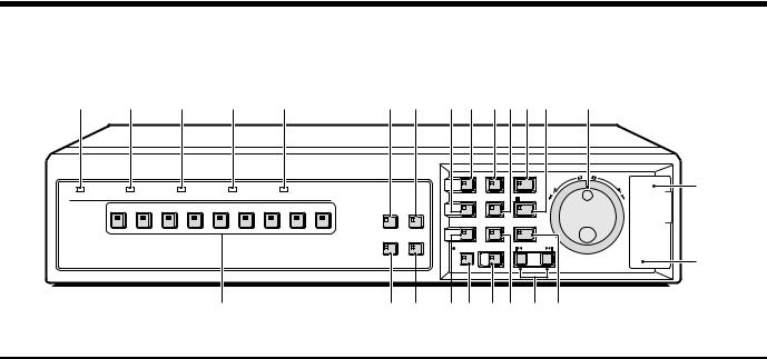
PART NAMES
 Front panel
1 2 3 4 5 |
|
|
7 8 H G KL O P S |
|
|
||||||||||
|
|
|
|
|
|
|
|
|
MENU |
EXIT/OSD |
PLAY/STOP |
R |
SHUTTLE |
E |
|
|
|
|
|
|
|
|
|
|
|
|
|
JOG |
|
||
|
|
|
|
|
|
|
|
|
|
|
|
A |
|
NT |
|
|
|
|
|
|
|
|
|
|
|
|
|
E |
|
E |
T |
|
|
|
|
|
|
|
|
|
|
|
|
L |
|
R |
|
|
|
|
|
|
|
|
|
|
|
|
|
C |
|
|
|
|
|
|
|
|
|
|
|
|
|
|
|
|
|
|
|
POWER |
FULL |
ALARM FULL |
LOCK |
|
ALARM |
|
|
ZOOM |
SEARCH |
STILL |
|
|
|
|
|
|
|
|
|
|
|
|
|
|
|
|
|
|
|||
1 |
2 |
3 |
4 |
5 |
6 |
7 |
8 |
9 |
QUAD MULTI |
|
|
|
|
|
|
|
|
|
|
|
|
|
|
|
|
|
|
|
|
|
|
|
|
MON2 PLUS |
(DSR-3009) |
6 |
9 F |
|
SEQUENCE COPY SHUTTLE HOLD
REC/STOP |
TIMER |
ALARM |
|
|
U |
I J N M R Q
1POWER indicator
•Illuminates (red) when the power cord plug is inserted into a wall outlet.
•Flashes when there is a problem with the internal hard disk or fan.
2FULL indicator
Flashes when overwriting is set to off and the remaining space in the normal recording area of the hard disk drops to 1%*.
In addition, if the amount of remaining space in the recording area drops to 0%, recording stops and the indicator stops flashing and illuminates steadily. If the “AREA FULL RESET” command in the main menu (See page 51.) is used, the indicator will switch off.
(* This can be changed using the menu settings.)
3ALARM FULL indicator
Flashes when overwriting is set to off and the remaining space in the alarm recording area of the hard disk drops to 1%*.
In addition, if the amount of remaining space in the recording area drops to 0%, recording stops and the indicator stops flashing and illuminates steadily. If the “AREA FULL RESET” command in the main menu (See page 51.) is used, the indicator will switch off.
(* This can be changed using the menu settings.)
4LOCK indicator
Illuminates when the security lock is engaged using the menu and operations are locked.
If a button is pressed while the lock is engaged, the buzzer sounds. The indicator will flash at this time and the password entry screen will be displayed on the monitor.
5ALARM indicator
Illuminates during pre-alarm recording. Flashes during alarm recording.
6Camera select buttons and indicators
When a camera is connected to one of the camera video input (CAMERA IN) connectors at the rear of the digital video recorder and the corresponding button is pressed, the indicator illuminates and images from that camera are displayed.
(Indicators)
•During split-screen monitoring, the indicators for all of the cameras being displayed in the split-screen illuminate.
•When there is alarm input, the indicator for the alarm input camera flashes.
74-screen display button and indicator (QUAD)
This button lets you switch the display to a 4-screen display while monitoring is being carried out using a single-screen, 16-screen display or 9-screen display.
When the QUAD button is pressed, the screen switches to 4-screen display, and the 4-screen display changes (1 – 4, 5 – 8, 9 – 12, 13 – 16) each time the QUAD button is then pressed. The indicator illuminates to match the 4-screen display.
•For the DSR-3009 model, the 4-screen display changes each time the QUAD button is pressed (1 – 4, 5 – 8, 9 – 3).
8Multiple display button and indicator (MULTI)
This button lets you switch the display to a 16-screen display or 9-screen display while monitoring is being carried out using the single-screen or 4-screen display.
When the MULTI button is pressed, the 9-screen display or 16-screen display appears, and the split-screen display then changes each time the button is pressed again.
•For the DSR-3009 model, a 9-screen display will appear. The 16-screen display is not available.
9Monitor 2 setting button (MON2)
If this button is pressed while a monitor is connected to the MON2 connector at the rear of the digital video recorder, the monitor 2 output status can be changed. The default setting is for automatic switching display. If a camera select button is pressed, images from the selected camera can be displayed. The indicator illuminates while monitoring is in progress.
FPlus display button and indicator (PLUS)
This button lets you display a specified image in the lower-right quarter of the screen area (6-screen display or 13-screen display). When the PLUS button is pressed, the lower-right quarter of the screen is displayed and the indicator flashes. If you press the camera select button for the images required, those images appear in the quarter screen. The following operations can be carried out when this quarter screen is being displayed.
•If the MULTI button is pressed, the screen changes to a 6-screen display or 13-screen display. The image in the quarter screen remains unchanged.
(For the DSR-3009 model, only the 6-screen display is available.)
•If the SEQUENCE button is pressed, the SEQUENCE indicator flashes and the quarter screen automatically changes. The automatic screen switching speed can be set using the menu screen. (See page 82.)
•If you press the PLUS button twice during playback, the camera images and the playback images are displayed.
English |
5 |
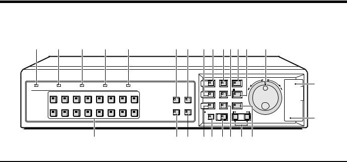
PART NAMES
1 2 3 4 5 |
|
7 8 H G KL O P S |
|
|
||||||||||
|
|
|
|
|
|
|
|
MENU |
EXIT/OSD |
PLAY/STOP |
R |
SHUTTLE |
E |
|
|
|
|
|
|
|
|
|
|
|
|
JOG |
|
||
|
|
|
|
|
|
|
|
|
|
|
A |
|
NT |
|
|
|
|
|
|
|
|
|
|
|
|
E |
|
E |
T |
|
|
|
|
|
|
|
|
|
|
|
L |
|
R |
|
|
|
|
|
|
|
|
|
|
|
|
C |
|
|
|
|
|
|
|
|
|
|
|
|
|
|
|
|
|
|
POWER |
FULL |
ALARM FULL |
LOCK |
|
ALARM |
|
ZOOM |
SEARCH |
STILL |
|
|
|
|
|
|
|
|
|
|
|
|
|
|
|
|
|
|||
1 |
2 |
3 |
4 |
5 |
6 |
7 |
8 |
QUAD MULTI |
|
|
|
|
|
|
|
|
|
|
|
|
|
|
|
|
|
|
|
|
|
|
|
SEQUENCE COPY |
SHUTTLE HOLD |
|
9 10 11 12 13 14 15 16 |
MON2 PLUS |
|
|
|
REC/STOP TIMER |
ALARM |
|
|
|
U |
(DSR-3016) |
6 |
9 F I J N M R Q |
|
|
|||
GMENU button and indicator
Used to display the menu screens (setting screens).
HZOOM button and indicator
Used to display the zoom screen in a single screen during image monitoring or playback.
The indicator flashes when the zoom screen is displayed.
IAutomatic camera switching button and indicator (SEQUENCE)
This button is used to automatically change the camera images that are being monitored in the single-screen, 4-screen or quarter-screen (plus-screen) display.
When the SEQUENCE button is pressed, the indicator flashes and the screen changes automatically. The camera indicator also changes to match the images on the screen.
JREC/STOP button and indicator
Use to start normal recording.
The indicator illuminates during recording.
If the button is pressed for 2 seconds or more during recording, recording stops and the indicator switches off.
KEXIT/OSD button and indicator
•When a menu screen is displayed The main menu or sub-menu is exited.
•During recording, playback or while stopped
If the button is pressed during recording or playback, superimposed information such as time and date and alarm status changes in the following order:
Displayed at top → Displayed at bottom → Not displayed The indicator illuminates while information is displayed.
LSEARCH button and indicator
If the button is pressed during recording or while the digital video recorder is stopped, the indicator illuminates and the search playback screen is displayed. If the button is pressed once more, the search playback screen is exited.
MCOPY button and indicator
If this button is pressed while the images being played back in a single screen are paused, the paused image is copied to the archive area of the hard disk or to a CompactFlash card, microdrive or CD-R drive.
The indicator illuminates during copying.
If the button is pressed during recording or while the digital video recorder is stopped, backups (copying to DAT) can be carried out.
NTIMER button and indicator
When the button is pressed when recording is stopped, the digital video recorder switches to timer recording standby mode, and when the setting time is reached, timer recording starts.
OPLAY/STOP button and indicator
The indicator illuminates and playback of images in the normal recording area and alarm recording area starts.
If pressed during playback, playback stops.
PSTILL button and indicator
When this button is pressed while images are being monitored or played back in a single screen, the indicator illuminates and the screen images are paused.
If it is pressed again, playback resumes.
QSHUTTLE LOCK button and indicator
If this button is pressed continuously for 2 seconds or more when the security lock has been set, the security lock is activated.
This locks the speed for playback and frame advance. The indicator illuminates while locked.
RALARM buttons (ûALARM ù)
When these buttons are pressed during playback, playback skips to the previous or next alarm recording.
SJog (inner) and shuttle (outer) dials
•During playback
The jog dial changes the playback speed. The shuttle dial fast-forwards and rewinds.
•Menu screens
The jog dial moves the cursor and changes settings. The shuttle dial accepts settings.
TCompactFlash card slot
Insert a CompactFlash card or microdrive here.
UMENU RESET button
Used to initialize menu settings (displayed menu settings only). If this button is pressed while images are being monitored, the time is reset (0 minutes and 0 seconds).
6 |
English |
PART NAMES
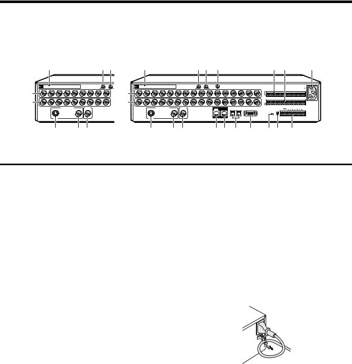
 Rear panel
DSR-3009 |
|
DSR-3016 |
|
|
|
1 |
23 |
1 |
23 4 |
M N |
O |
|
|
|
|
|
|
|
PC Card SLOT |
|
|
|
|
|
|
|
|
|
|
AUDIO IN |
A |
5 |
1 |
2 |
3 |
4 |
5 |
6 |
7 |
8 |
9 |
6 |
|
|
|
|
|
|
|
|
|
|
|
|
|
MAIN MONITOR |
|
MON2 |
|
|
|
SVHS |
78 9
|
|
|
|
|
|
|
PC Card SLOT |
|
|
|
MIC |
|
|
|
|
|
|
|
|
|
|
|
|
|
|
|
|
|
|
|
|
AC IN~ |
||
|
|
|
|
|
|
|
|
|
|
IN |
|
|
|
|
|
|
|
|
|
|
|
|
|
|
|
|
|
|
|
|
||||
|
|
|
|
|
|
|
|
AUDIO IN |
9 |
10 |
AUDIO OUT |
|
|
|
|
|
ALARM IN |
|
|
|
|
|
|
|
|
|
|
|
|
|
|
|
||
5 |
1 |
2 |
3 |
4 |
5 |
6 |
7 |
8 |
11 |
12 |
13 |
14 |
15 |
16 |
|
|
|
|
|
|
|
|
|
|
|
|
|
|
|
|||||
|
|
|
|
|
|
|
|
|
|
|
|
|
|
|
|
|
C |
1 |
2 |
3 |
4 |
5 |
6 |
7 |
8 |
9 |
10 |
11 |
12 |
13 |
14 |
15 |
16 |
|
6 |
|
|
|
|
|
|
|
|
|
|
|
|
|
|
|
|
SENSOR |
|
|
|
|
|
|
CLOCK ALAALARM N R |
|
|
ALAR |
|
|
|||||
|
|
|
|
|
|
|
|
|
|
|
|
|
|
|
|
|
|
|
|
|
|
|
|
|
|
|
NO |
WA |
|
|
|
|
|
|
|
|
|
|
MAIN MONITOR |
|
MON2 |
|
|
|
|
DIGITAL |
|
RS485 |
|
|
ALARM OUT |
|
|
|
RS485 |
REMOTE |
SET |
RM |
|
REC NING |
|
|
M |
|
|
||||
|
|
|
|
|
|
|
|
IN |
A |
|
RS232C |
|
|
|
|
|
OUT OUTRESET OUT OUT |
FULL FULL |
|
|
||||||||||||||
|
|
|
|
|
|
|
|
|
|
|
OUT |
B |
|
|
|
|
|
TERMINATE |
C |
R1 |
R2 |
|
|
|
|
|
|
|
|
C |
||||
|
|
|
|
|
|
|
|
|
|
|
|
|
|
|
|
|
|
|
ALL |
|
ON |
|
|
|
|
|
|
|
|
|
|
|
|
|
|
|
|
|
|
|
|
|
|
|
|
|
|
|
|
|
|
|
|
RESET |
|
|
|
|
|
|
|
|
|
|
|
|
|
|
|
|
|
|
|
|
|
|
|
|
|
|
|
|
|
|
|
|
|
|
|
|
OFF |
|
|
|
|
|
CONTROL |
|
|
|
|
|||
|
|
|
SVHS |
|
|
|
|
|
|
|
|
|
DO NOT CONNECT TO PHONE LINE |
|
|
|
|
|
|
|
|
|
|
|
|
|
|
|
|
|||||
|
|
|
|
|
|
|
|
|
|
|
|
|
|
|
|
|
|
|
|
|
|
|
|
|
|
|
|
|
|
|
|
|||
7 8 9 |
F G H I J K L |
 P
P
1PC card slot
Connect a network card or SCSI card (sold separately) here. Note: The PC card slot is for 16-bit 5 V cards only.
Do not use 32-bit card bus types of card, as they may damage the PC card slot of the digital video recorder.
2AUDIO IN terminal
3AUDIO OUT terminal
4MIC IN terminal
5VIDEO IN terminal
The DSR-3009 model has nine input terminals.
6VIDEO OUT terminal
The DSR-3009 model has nine output terminals.
7MAIN MONITOR S-VIDEO output terminal
8MAIN MONITOR output terminal
9MON2 output terminal
FDIGITAL IN terminal
GDIGITAL OUT terminal
HRS485 control terminal
IRS-232C terminal
JALL RESET button
KRS-485 termination switch
LControl connector
Pin |
Signal |
C |
Ground |
REMOTE R1 |
Remote control input 1 |
REMOTE R2 |
Remote control input 2 |
CLOCK SET OUT |
Clock setting output (See page 46.) |
ALARM OUT |
Alarm output |
ALARM RESET |
Alarm reset |
NON REC OUT |
Non REC output |
WARNING OUT |
HDD error warning output |
FULL |
HDD space warning output |
ALARM FULL |
Alarm recording area space warning |
|
output |
C |
Ground |
|
|
MALARM IN terminals (1 – 16)
These terminals send alarm signals resulting from the operation of externally-connected alarm switches to the ALARM OUT control terminal for output.
The DSR-3009 model has nine alarm input terminals.
NSENSOR ALARM OUT terminal (1 – 16)
When a response is received from a motion sensor that has been set using the menu settings, an alarm signal is output. (open collector)
The DSR-3009 model has nine alarm output terminals. Note: This connector is not an output connector for the alarm
input connectors that are used for external alarms.
OAC power socket (AC IN~)
Securely insert the accessory power cord here.
PPower cord holder
Secure the power cord to the holder using the accessory cord tie as shown in the illustration.
English |
7 |

CONNECTIONS
Turn off the power for all components before connecting them.
Be sure to carefully read the Instruction Manual for all equipment being connected to the digital video recorder. If the connections are incorrect, smoke or operating malfunctions may result.
 Basic connections (DSR-3016 model)
Nine cameras can be connected to the DSR-3009 model.
|
|
|
|
|
|
PC Card SLOT |
|
|
|
MIC |
MIC IN |
|
|
|
|
AC IN~ |
|
|
|
|
|
|
|
|
|
IN |
|
|
|
|
|||
1 |
|
|
|
|
|
|
AUDIO IN |
|
|
AUDIO OUT |
|
|
|
|
|
ALARM IN |
2 |
3 |
4 |
5 |
6 |
7 |
8 |
9 |
10 |
11 |
12 |
13 |
14 |
15 |
16 |
C |
1 |
2 |
3 |
4 |
5 |
6 |
7 |
8 |
9 |
10 |
11 |
12 |
13 |
14 |
15 |
16 |
MAIN MONITOR |
MON2 |
SVHS
|
|
|
|
DIGITAL |
|
RS485 |
SENSOR |
||||||||
|
|
|
|
|
ALARM OUT |
||||||||||
|
IN |
|
|
|
|
OUT |
A |
|
|
B |
RS232C |
||||
|
|
|
|
|
|
|
|
|
|
|
|
|
|
|
|
|
|
|
|
|
|
|
|
|
|
|
|
|
|
|
|
|
|
|
|
|
|
|
|
|
|
|
|
|
|
|
|
DO NOT CONNECT TO PHONE LINE
|
|
CLOCK |
|
ALARM |
NON |
RECWARNING |
ALARM |
|
|
|
REMOTE |
SETALARM |
|
||||
|
RS485 |
|
UT |
|
OUT |
RESET OUT OUT |
FULL FULL |
|
|
|
O |
|
|
|
|
|
|
|
TERMINATE C R1 |
R2 |
|
|
|
|
C |
|
ALL |
ON |
|
|
|
|
|
|
|
RESET |
|
|
|
|
|
|
|
|
|
OFF |
|
|
|
|
|
|
|
CONTROL
S-VIDEO IN |
VIDEO IN |
Computer |
|||||||
connector |
connector |
|
|
|
|
|
|
||
|
|
|
|
|
|
|
|
|
|
|
|
|
|
|
|
|
|
|
|
|
|
|
|
|
|
|
|
|
|
|
|
|
|
|
|
|
|
|
|
|
|
|
|
|
|
|
|
|
|
|
|
|
|
|
|
|
|
|
|
|
|
|
|
|
|
|
|
|
|
TV monitor |
TV monitor |
(sold separately) |
(sold separately) |
 Connecting high image quality (S-VHS) video equipment
MAIN MONITOR |
MON2 |
DIGITAL |
A |
RS485 |
ALARM OUT |
|
IN |
OUT |
B |
RS232C |
|
SVHS |
|
|
DO NOT CONNECT TO PHONE LINE |
|
|
|
|
C |
S |
ALARM |
NON |
|
W |
|
|
|
|
|
|
K |
|
|
|
|
|
|
|
||
|
|
LOC |
ETALARM |
|
|
RECARNING |
|
ALARM |
|
||
|
RS485 |
REMOTE |
OUT |
|
OUT |
FULL |
|||||
|
|
OUT |
|
RESET |
OUT |
FULL |
|||||
|
TERMINATE C R1 |
R2 |
|
|
|
|
|
|
|
C |
|
ALL |
ON |
|
|
|
|
|
|
|
|
|
|
RESET
OFF
CONTROL
 S-VIDEO IN connector
1 2 3 4
5 6 7 8
9 10 11 12
13 14 15 16
 Connecting to an Amplifier
|
Audio output |
|
Amplifier |
|
|
(sold separately) |
Audio input |
|
|
PC Card SLOT |
MIC |
|
IN |
|
|
AUDIO IN |
AUDIO OUT |
1 |
2 |
3 |
4 |
5 |
6 |
7 |
8 |
9 |
10 |
11 |
|
|
|
MAIN MONITOR |
|
MON2 |
|
|
|
|
|
IN
SVHS
8 |
English |
CONNECTIONS
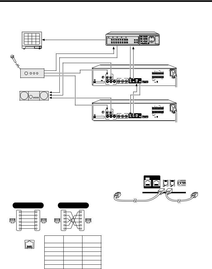
 Digital series connections
Digital video recorder (main)
1 |
2 |
3 |
4 |
|
|
|
|
|
|
|
|
|
|
|
5 |
6 |
7 |
8 |
|
POWER |
FULL |
|
ALARM FULL |
|
LOCK |
ALARM |
|||
|
|
|
|
|
|
|
1 |
2 |
3 |
4 |
5 |
6 |
7 |
8 |
9 |
10 |
11 |
12 |
|
|
|
9 |
10 |
11 |
12 |
13 |
14 |
15 |
16 |
13 |
14 |
15 |
16 |
|
|
|
|
|
|
|
|
|
|
|
TV monitor |
|
|
|
|
|
|
|
|
|
|
|
|||
(sold separately) |
|
|
|
|
|
|
|
|
|
|
|
|||
|
|
|
|
MIC |
|
AUDIO |
|
|
|
|
|
|
|
|
|
|
|
|
IN |
IN |
|
OUT |
|
|
|
|
|
|
|
|
|
|
|
|
|
|
|
|
|
|
|
VIDEO |
|
|
Amplifier |
|
|
|
|
|
|
IN |
|
LOOP OUT |
OUT |
||||
PC Card SLOT |
|
|
|
|
|
|
|
|
|
|
||||
|
|
|
|
|
|
|
|
|
|
|
||||
(sold separately) |
|
IN |
LOOP OUT |
OUT |
|
|
|
|
|
|
||||
|
|
S-VIDEO |
|
|
|
|
|
|
|
|||||
|
|
|
|
|
|
|
|
|
|
|
||||
|
|
|
|
(sold separately) |
|
|
|
|
|
|
||||
Amplifier |
|
|
|
|
|
|
|
|
|
|
|
|||
(sold separately) |
|
|
AUDIO |
|
|
|
|
|
|
|
|
|||
|
|
|
|
MIC |
|
|
|
|
|
|
|
|
|
|
|
|
|
|
IN |
IN |
|
OUT |
|
|
|
|
|
|
|
VIDEO
IN LOOP OUT OUT
PC Card SLOT 
IN LOOP OUT OUT
S-VIDEO
(sold separately)
MENU |
EXIT/OSD |
PLAY/STOP |
EN |
|
|
|
TER |
ZOOM |
SEARCH |
STILL |
|
QUAD MULTI |
|
|
|
SEQUENCE |
COPY |
SHUTTLE LOCK |
|
MON2 PLUS |
|
|
|
REC/STOP |
TIMER |
ALARM |
|
Digital video recorder (sub 1)
|
|
|
|
ALARM |
|
CLOCK |
AC IN |
|
|
|
|
RESET |
|
ADJUST |
|
|
|
|
ALARM ALARM |
|
|
||
|
|
|
C IN |
OUT C |
IN OUT |
FULL |
|
|
DIGITAL |
C A |
B |
C REMOTE C |
NC NC C |
C |
|
IN |
|
RS485 |
|
SW |
|||
OUT |
SUB IN SUB OUT |
RS232C |
|
TERMINATE |
OUT |
||
|
|
|
RS485 |
ALL |
ON |
|
|
|
|
|
RESET |
|
|
||
|
|
|
|
|
OFF |
|
|
|
|
Digital video recorder (sub 2) |
||||||
|
|
|
|
ALARM |
|
CLOCK |
|
AC IN |
|
|
|
|
RESET |
|
ADJUST |
|
|
|
|
|
ALARM ALARM |
|
|
|
||
|
|
C |
IN |
OUT C |
IN OUT |
|
FULL |
|
|
DIGITAL |
C A |
|
B |
C REMOTE C |
NC NC |
C |
C |
IN |
|
|
RS485 |
|
|
SW |
||
OUT SUB IN SUB OUT |
RS232C |
|
|
TERMINATE |
|
OUT |
||
|
|
RS485 |
ALL |
ON |
|
|
|
|
|
|
RESET |
|
|
|
|||
|
|
|
|
|
OFF |
|
|
|
 System control connections
Use the RS-485 connector to connect a system controller (sold separately) to the digital video recorder. After connecting the system controller, you will need to carry out the settings that are given in the RS-232C/RS-485 SET menu. (See page 76.)
When using the RS485 (RJ-11) connector
Connect modular cables (sold separately) to the RS485 control connectors at the rear of the digital video recorder.
•If using a straight-type cable
Connect connector A to connector A and connector B to connector B.
•If using a cross-type cable
Connect connector A to connector B and connector B to connector A.
|
|
Straight type |
|
|
|
|
|
Cross type |
|
|
|
||
|
|
1 |
Spare |
1 |
|
|
|
|
1 |
Spare |
1 |
|
|
|
|
Spare |
|
|
|
|
Spare |
|
|
||||
|
|
2 |
2 |
|
|
|
|
2 |
2 |
|
|
||
1 |
6 |
|
1 |
6 |
1 |
6 |
|
1 |
6 |
||||
3 |
|
3 |
3 |
|
3 |
||||||||
|
|
4 |
Spare |
4 |
|
|
|
|
4 |
|
4 |
|
|
|
|
5 |
5 |
|
|
|
|
5 |
|
5 |
|
|
|
|
|
Spare |
|
|
|
|
Spare |
|
|
||||
|
|
6 |
6 |
|
|
|
|
6 |
6 |
|
|
||
|
|
|
|
|
|
|
|
|
|||||
|
|
|
|
|
|
|
Spare |
|
|
||||
|
|
|
|
|
|
|
|
|
|
|
|
|
|
Pin locations |
|
|
|
|
|
Pin number |
|
Connector A |
|
Connector B |
|||
|
|
|
|
|
|
|
|
signal |
|
|
signal |
||
|
|
|
|
|
|
|
|
|
|
|
|
||
|
|
|
|
|
|
|
1 |
|
|
Not used |
|
|
Not used |
|
|
|
1 |
6 |
|
|
2 |
|
|
Not used |
|
|
Not used |
NOTE: Do not connect to phone line. |
|
|
3 |
|
|
A |
|
|
B |
||||
|
|
|
|
|
|
|
|
|
|
|
|||
|
|
|
|
|
|
|
4 |
|
|
B |
|
|
A |
|
|
|
|
|
|
|
5 |
|
|
Not used |
|
|
Not used |
|
|
|
|
|
|
|
6 |
|
|
Not used |
|
|
Not used |
A:Non-inverting driver output/receiver input
B:Inverting driver output/receiver input
|
DIGITAL |
|
RS485 |
|
IN |
OUT |
A |
B |
RS23 |
To other |
|
To other |
connector A |
DO NOT CONNECT TO PHONE LINE |
connector A |
Straight-type cable |
Cross-type cable |
|
English |
9 |
CONNECTIONS
 External alarm sensor setup
In order to make an external alarm sensor operate, an external switch must be connected to an ALARM IN connector. When an intruder activates the external switch (such as by opening a door), an alarm signal is received and an alarm can be made to sound.
The DSR-3009 model uses the connectors marked *.
Connect an external switch to an ALARM IN connector
 *
*
 *
*
 *
*
 *
*
 *
*
 *
*
 *
*
 *
*
 *
*
SENSOR ALARM OUT connector
 Using as a monitor board during a motion sensor alarm
When the motion sensor built into the digital video recorder responds to an alarm, it outputs an alarm signal to the SENSOR ALARM OUT connector. If a switching circuit such as a warning lamp is connected to this connector, the warning lamp will illuminate when there is a response from the motion sensor. If the warning lamp is fixed somewhere in the layout diagram for an area such as a factory, the location of the camera can be ascertained in an instant during an emergency. The pin corresponding to the number of the camera that generates a sensor response switches to Low.
1K |
|
Rated values for each pin (at 25˚C) |
|||
|
|
|
|
• Max. current |
25mA |
|
|
|
|
||
|
|
|
|
• Max. voltage |
25V |
|
|
|
|
• Max. power |
40mW |
|
|
|
|
||
|
|
|
|
|
|
 Connecting a remote control circuit
If a remote control circuit is constructed as shown in the illustration and connected to the remote control input (R1 and R2) terminals of the CONTROL connector, the didital video recorder can be operated by remote control. (Contact LOW input)
The DSR-3009 model can control up to nine cameras.
|
|
|
|
|
|
|
|
|
|
|
|
|
|
|
AC IN ~ |
||
ALARM IN |
|
|
|
|
|
|
|
|
|
|
|
|
|
|
|
||
C |
1 |
2 |
3 |
4 |
5 |
6 |
7 |
|
8 |
9 |
10 |
11 |
12 |
13 |
14 |
15 |
16 |
SOR |
|
|
|
|
|
|
CL |
|
|
A |
NO |
W |
|
A |
|
|
|
|
|
|
|
|
|
O |
|
|
|
A |
|
|
|
|
|||
|
|
|
|
|
|
CK |
ALA LARM NR RN |
LAR |
|
|
|||||||
M OUT |
|
|
|
RS485 |
REMOTE |
SET RM |
RE |
EC |
ING |
M |
|
|
|||||
|
|
|
|
|
|
OUT |
OUT SET OUT OUT FULL |
FULL |
|
|
|||||||
|
|
|
|
TERMINATE |
C |
R1 |
|
R2 |
|
|
|
|
|
|
|
C |
|
|
|
ALL |
|
ON |
|
|
|
|
|
|
|
|
|
|
|
|
|
|
|
RESET |
|
|
|
|
|
|
|
|
|
|
|
|
|
|
|
|
|
|
|
OFF |
|
|
|
|
|
|
CONTROL |
|
|
|
|||
|
|
|
|
|
|
|
|
|
|
|
|
|
|
||||
SW: Switch
Note:
•The remote control cable should be no more than 5 m long.
•Use a resistance of 1/10 ohms or more and with a D ranking (precision within ±0.5%).
R1
(When used alone) (When R2 SHIFT key 220Ω is also pressed)
; Spare
220Ω
SW 2: Camera2* |
; Spare |
300Ω
SW 3: Camera3* |
; Spare |
360Ω
SW 4: Camera4* |
; Automatic switching display |
470Ω
SW 5: Camera5* |
; Monitor 2 |
680Ω
SW 6: Camera6* |
; Plus screen display |
820Ω
SW 7: Camera7* |
; 4-screen display |
1.2kΩ
SW 8: Camera8* |
; Multi-screen display |
1.8kΩ
SW 9 : Camera9* |
; Menu reset |
2.2kΩ
SW 10 : Camera10 ; Spare
3.3kΩ
SW 11 : Camera11 ; Spare
4.7kΩ
SW 12 : Camera12 ; Spare
7.5kΩ
SW 13 : Camera13 ; Spare
13kΩ
SW 14 : Camera14 ; Spare
27kΩ
SW 15 : Camera15 ; Spare
68kΩ
SW 16 : Camera16 ; Spare
R2
 220Ω
220Ω
SW 17: Recording stop
 220Ω
220Ω
SW 18: Playback stop
 300Ω
300Ω
SW 19: Pause
 360Ω
360Ω
SW 20: Search
 470Ω
470Ω
SW 21: SHIFT (When R1 and R2 are pressed)
 680Ω
680Ω
SW 22: Playback
 820Ω
820Ω
SW 23: Recording
 1.2kΩ
1.2kΩ
SW 24: Menu
 1.8kΩ
1.8kΩ
SW 25: Menu clear (Exit)
 2.2kΩ
2.2kΩ
SW 26: +
 3.3kΩ
3.3kΩ
SW 27: –
 4.7kΩ
4.7kΩ
SW 28: 3
 7.5kΩ
7.5kΩ
SW 29: 2
 13kΩ
13kΩ
SW 30: Zoom
 27k
27k
SW 31: Copy
 68kΩ
68kΩ
SW 32: Timer recording
10 |
English |
BUILT-IN HARD DISK
 Hard disk
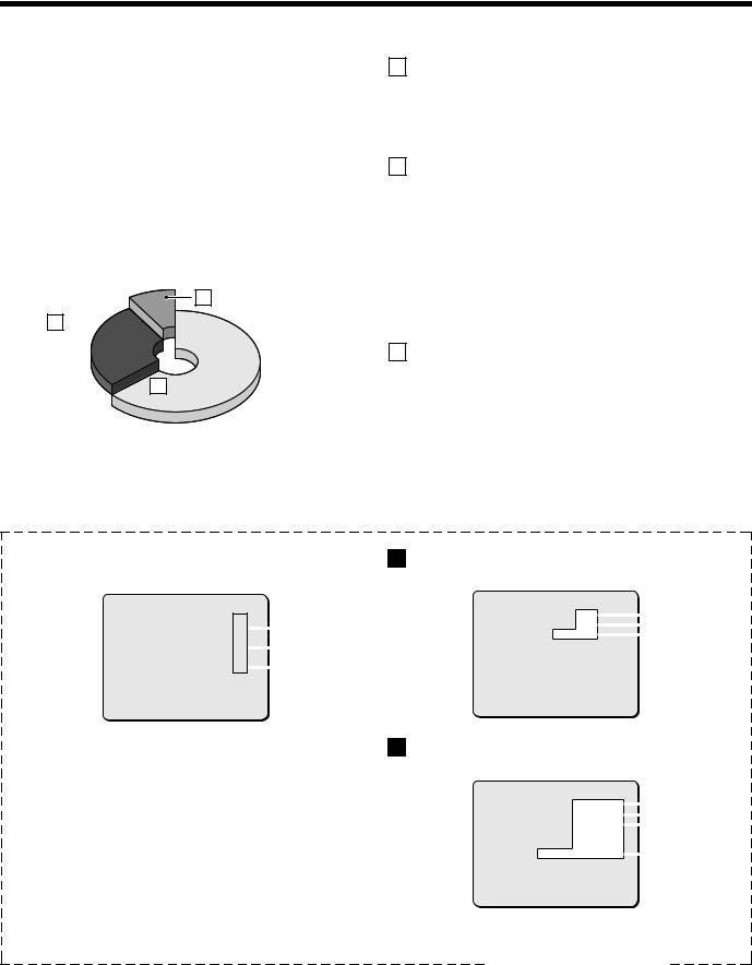
Recording areas
The recording areas on the hard disk (normal recording area: 80%, alarm recording area: 19%, archive area: 1%) are established automatically when the power for the digital video recorder is turned on. Images are recorded in the normal recording area when the REC/STOP button is pressed, and they are recorded in the alarm recording area when an alarm occurs. This is called the default condition, and the following detailed settings can be confirmed in the sections on “RECORDING IMAGES IN THE NORMAL RECORDING AREA” and “RECORDING IMAGES IN THE ALARM RECORDING AREA” (See page 22.) which are explained later. Furthermore, settings such as the recording areas and picture quality can be changed using the menu screens.
C Archive area
1%
BAlarm recording area
80%
19%
A Normal recording area
Hard disk recording areas
Menu screen (initial setting)
This can be displayed by pressing the MENU button.
|
<RECORDING AREA SET> |
|
|
|
|
|
|
|
TOTAL CAPACITY |
: |
80GB |
|
|
|
|
||
NORMAL RECORDING AREA |
: |
80 |
% |
|
A |
|
A |
|
|
||||||||
AREA |
FULL RESET |
-> |
|
|
|
|
|
|
ALARM RECORDING AREA |
: |
19 |
% |
|
B |
|
B |
|
|
|
|||||||
AREA |
FULL RESET |
-> |
|
|
|
|
|
|
ARCHIVE |
AREA |
: |
1 |
% |
|
C |
|
|
|
|
|
||||||
AREA |
FULL RESET |
-> |
|
|
|
|
|
|
|
|
|
|
|
|
|||
|
|
|
|
|
|
|||
CAUTION : WHEN THE AREA SETTING IS CHANGED,
THE WHOLE AREA WILL BE INITIALIZED !
A Normal recording area
•When the REC/STOP button is pressed while monitoring is in progress, images are recorded in the normal recording area.
•When start and end times are entered for each day of the week and are then enabled, timer recording is automatically carried out in the normal recording area between the times that have been set.
B Alarm recording area
ALARM REC MODE SET menu settings are required.
•Alarm recording is enabled when ALARM RECORDING is set. When a suspicious person is detected by the switch or motion sensor that is connected to the alarm input terminal, an alarm is recorded in the alarm recording area.
•Pre-alarm recording is enabled when PRE-ALARM RECORDING is set. Pre-alarm recording repeatedly records the same images as for normal recording in the alarm recording area, and overwrites these images after the set time interval, until an alarm is detected. When pre-alarm recording is set, the image immediately before an alarm occurred can be recorded.
C Archive area
This is the area for copying important images from the normal recording area and the alarm recording area. The size of the archive area can be set to a maximum of 10 GB (12% of total capacity when using an 80-GB hard disk, 6% of total capacity when using an 160-GB hard disk) by changing the size of the normal recording area or the alarm recording area.
ASetting screen for normal recording area picture quality, recording speed, etc.
|
<NORMAL REC MODE SET> |
|
|
|
|
|
PICTURE QUALITY |
: NORMAL |
|
|
|
1 |
|
|
|
|
||||
AUDIO RECORDING |
: ON |
|
2 |
|||
|
||||||
REC |
RATE : |
10FPS ( 57H) |
|
|
3 |
|
|
|
|||||
REC |
PROGRAM GROUP |
: OFF |
|
|
|
|
1PICTURE QUALITY: NORMAL
Picture quality can be selected from five options.
(The recording speed changes in accordance with the picture quality selected.)
2AUDIO RECORDING: Can be set to ON or OFF.
3REC RATE: Shows the recording interval and the recording time.
Refer to the recording speed table for further details.
4ALARM RECORDING: Can be set to ON or OFF.
When alarm recordings are to be made, select a setting such as ENABLED for the OFF setting. The recording speed and alarm duration will be displayed
BSetting screen for alarm recording area picture quality, recording speed, etc.
|
|
|
|
<ALARM REC MODE SET> |
|
|
|
|
|
|
|
|
|
||||||||||||||||
PICTURE QUALITY |
|
|
: |
SUPER FINE |
|
|
|
|
1 |
||||||||||||||||||||
|
|
|
|
|
|
||||||||||||||||||||||||
AUDIO |
RECORDING |
|
|
: |
ON |
|
|
2 |
|
|
|||||||||||||||||||
|
|
|
|
|
|
||||||||||||||||||||||||
ALARM |
RECORDING |
|
|
: |
ENABLED |
|
|
|
4 |
||||||||||||||||||||
|
|
|
|
|
|||||||||||||||||||||||||
ALARM |
INTERLEAVE |
|
|
: |
ONLY |
|
|
|
|
|
|
|
|
|
|||||||||||||||
PROGRAM GROUP |
|
|
: |
OFF |
|
|
|
|
|
|
|
|
|
||||||||||||||||
|
REC |
RATE :@ |
0.1FPS, |
|
DURATION: 40SEC |
|
|
3 |
|||||||||||||||||||||
|
|
|
|
||||||||||||||||||||||||||
PRE-ALARM RECORDING |
: |
ON |
|
|
|
|
|
|
|
|
|
||||||||||||||||||
|
REC |
RATE :@ **** FPS, |
|
DURATION: *** |
|
|
|
|
|
|
|
|
|
||||||||||||||||
=> |
(01010 ALARMS CAN BE RECORDED ) |
|
|
|
|
|
|
|
|
|
|||||||||||||||||||
ALARM |
TRIGGER |
|
|
: |
ALARM |
|
|
|
|
|
|
|
|
|
|||||||||||||||
|
|
|
|
|
|
|
|
|
|
|
|
|
|
|
|
|
|
|
|
|
|
|
|
|
|
|
|
|
|
English |
11 |

BUILT-IN HARD DISK
 Recording speed tables (The recording time may vary depending on the images being recorded.)
These recording speed tables show the recording times for various picture quality and frame/field settings when recording in the normal recording area of the hard disk (80 GB). They do not include audio recording settings.
The recording times for the normal recording area and the alarm recording area represent the recording time values given in the recording speed tables, multiplied by the percentages for the normal recording area and alarm recording area that have been set using the recording area setting menu commands.
 When recording with an 80-GB hard disk at 100% capacity
Recording Rate (field/sec) |
|
|
RECORDING TIME |
|
|
BASIC |
NORMAL |
ENHANCED |
FINE |
SUPER FINE |
|
|
15 kB |
22 kB |
30 kB |
40 kB |
56 kB |
60.00 |
21H |
15H |
11H |
8H |
6H |
30.00 |
42H |
30H |
22H |
16H |
12H |
20.00 |
63H |
45H |
33H |
24H |
18H |
15.00 |
85H |
60H |
45H |
32H |
24H |
10.00 |
127H |
90H |
67H |
49H |
37H |
7.50 |
170H |
120H |
90H |
65H |
49H |
6.00 |
212H |
150H |
113H |
82H |
62H |
5.00 |
255H |
180H |
135H |
98H |
74H |
4.29 |
297H |
210H |
158H |
115H |
87H |
3.75 |
340H |
241H |
180H |
131H |
99H |
3.33 |
382H |
271H |
203H |
147H |
112H |
3.00 |
425H |
301H |
226H |
164H |
124H |
2.73 |
468H |
331H |
248H |
180H |
137H |
2.31 |
553H |
391H |
293H |
213H |
162H |
2.00 |
638H |
452H |
339H |
246H |
187H |
1.67 |
765H |
542H |
406H |
295H |
224H |
1.43 |
893H |
632H |
474H |
345H |
261H |
1.25 |
1021H |
723H |
542H |
394H |
299H |
1.11 |
1148H |
813H |
610H |
443H |
336H |
1.00 |
1276H |
904H |
678H |
493H |
374H |
0.50 |
2553H |
1808H |
1356H |
986H |
748H |
0.33 |
3829H |
2712H |
2034H |
1479H |
1122H |
0.25 |
5106H |
3616H |
2712H |
1972H |
1496H |
0.20 |
6382H |
4521H |
3390H |
2466H |
1870H |
0.10 |
12765H |
9042H |
6781H |
4932H |
3741H |
0.05 |
25531H |
18084H |
13563H |
9864H |
7483H |
0.03 |
38296H |
27126H |
20345H |
14796H |
11224H |
The tables below are recording time tables provided for reference if the total capacity of the hard disk has been increased to 160 GB. (Contact the place of purchase for details on increasing the capacity of the hard disk.)
 When recording with a 160-GB hard disk at 100% capacity
Recording Rate (field/sec) |
|
|
RECORDING TIME |
|
|
BASIC |
NORMAL |
ENHANCED |
FINE |
SUPER FINE |
|
|
15 kB |
22 kB |
30 kB |
42 kB |
56 kB |
60.00 |
42H |
30H |
22H |
16H |
12H |
30.00 |
85H |
60H |
45H |
32H |
24H |
20.00 |
127H |
90H |
67H |
49H |
37H |
15.00 |
170H |
120H |
90H |
65H |
49H |
10.00 |
255H |
180H |
135H |
98H |
74H |
7.50 |
340H |
241H |
180H |
131H |
99H |
6.00 |
425H |
301H |
226H |
164H |
124H |
5.00 |
510H |
361H |
271H |
197H |
149H |
4.29 |
595H |
421H |
316H |
230H |
174H |
3.75 |
680H |
482H |
361H |
263H |
199H |
3.33 |
765H |
542H |
406H |
295H |
224H |
3.00 |
851H |
602H |
452H |
328H |
249H |
2.73 |
936H |
663H |
497H |
361H |
274H |
2.31 |
1106H |
783H |
587H |
427H |
324H |
2.00 |
1276H |
904H |
678H |
493H |
374H |
1.67 |
1531H |
1085H |
813H |
591H |
448H |
1.43 |
1787H |
1265H |
949H |
690H |
523H |
1.25 |
2042H |
1446H |
1085H |
789H |
598H |
1.11 |
2297H |
1627H |
1220H |
887H |
673H |
1.00 |
2553H |
1808H |
1356H |
986H |
748H |
0.50 |
5106H |
3616H |
2712H |
1972H |
1496H |
0.33 |
7659H |
5425H |
4069H |
2959H |
2244H |
0.25 |
10212H |
7233H |
5425H |
3945H |
2993H |
0.20 |
12765H |
9042H |
6781H |
4932H |
3741H |
0.10 |
25531H |
18084H |
13563H |
9864H |
7483H |
0.05 |
51062H |
36168H |
27126H |
19728H |
14966H |
0.03 |
76593H |
54253H |
40690H |
29592H |
22449H |
Reference: 24H = 1 day, 168H = 1 week, 720H = 1 month, 8760H = 1 year
12 |
English |
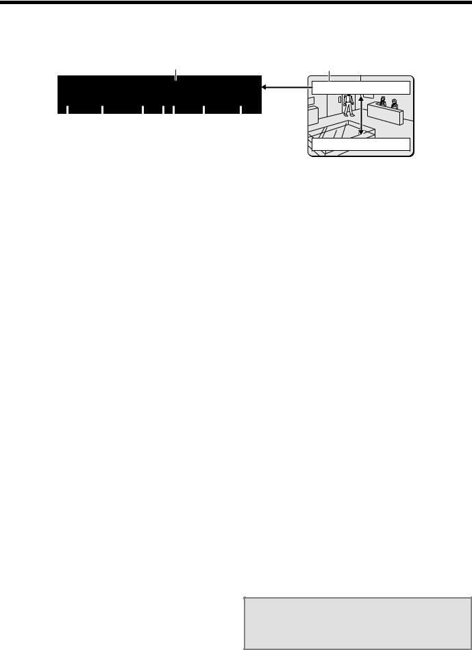
BUILT-IN HARD DISK
When the power for the digital video recorder is turned on, the operating display appears at the top of the monitor screen. This operating display shows information which is essential for operation, such as the date, time and picture quality.
1 |
Operating display |
|
|
|
|
|
|
|
|
|
|
|
|
|
|
|
|
|
|
|
|
|
|
|
|
|
|
|
|
|
|
|
|
|
|
|
|
|
|
02 |
|
|
|
|
|
|
|
||||
|
REC |
|
ALARM |
|
|
0000 |
|
REPEAT |
|
EN |
|
A |
|
|
01-01-02 |
|
00:00:00 |
|
||||||
|
|
|
|
|
|
|
|
|
|
|
|
|
|
|
|
|
|
|
|
|
|
|
|
|
|
|
|
|
|
|
|
|
|
|
|
|
|
|
|
|
|||||||||
2 |
|
|
3 |
4 |
56 |
7 |
8 |
|
||||||||||||||||
02
REC ALARM 0000 REPEAT EN A 01-01-02 00:00:00
REC ALARM  0000 REPEAT EN A 01-01-02 00:00:00 02
 Operating display
Insert the power cord into a wall outlet and turn on the power.
The POWER indicator illuminates, and after approximately 15 seconds the EXIT/OSD indicator illuminates. The camera images then appear on the monitor screen and the operating display appears at the top of the screen.
Note: If you press the EXIT/OSD button repeatedly, you can change the display position for the operating display or make it disappear.
1Camera number display
This displays the number of the camera that is currently being played back or monitored.
2Operating symbol display
These symbols appear during recording and playback.
REC : Recording |
e : Fast forward |
|
c : Playback |
f : Rewind |
|
d |
: Reverse playback |
hc : Slow playback |
h |
: Stopped |
dh : Slow reverse playback |
Note: If recording and playback are being carried out at the same time, the playback symbol (c) appears.
3Alarm display and alarm number display
When an alarm setting is made using the ALARM REC MODE SET menu item, The following display appears in the alarm display. However, the PRE display appears when pre-alarm recording has been set. When an alarm occurs, the PRE is replaced by ALARM and the number of alarms also appears. The alarm display shows the cumulative number of alarms.
•If ALARM REC MODE SET is set: “ALARM” appears. The “ALARM” display flashes during alarm recording.
•If PRE ALARM RECORDING is set: “PRE” appears.
•When playing images from the archive area: ARCHIV appears.
•When an external alarm is received: “EA” flashes to the left of the camera number.
•When a motion sensor alarm is received: “SA” flashes to the left of the camera number.
4Amount of recording area remaining
“REPEAT” appears when overwriting is enabled. Furthermore, if overwriting has been disabled (OVERWRITE: OFF) for the normal recording area and the alarm recording area, the amount of space remaining appears as a percentage.
You can change the amount of recording area remaining using the RECORDING AREA SET menu item. (See page 51.)
5Picture quality display
This shows the picture quality for images that are recorded on the hard disk. The default setting is EN (Enhanced). The display changes when the picture quality is changed using the NORMAL REC MODE SET menu item.
•BA: Basic
•NO: Normal
•EN: Enhanced
•FI: Fine
•SF: Super Fine
6Audio recording display
“A” appears when audio recording is enabled. See page 54 for details on the audio recording settings.
7Date display
When the digital video recorder is first turned on, the date appears as 01-01-02 (month, day, year). Make sure that you use the menus to set the correct date.
8Time display
When the digital video recorder is first turned on, the time appears as 00:00:00, and the time starts counting after the date has been set. The digital video recorder uses the date and time to control recording and playback, so if the date and time have not been set, the correct images cannot be retrieved. Make sure that you use the menus to set the correct time. If this is not set, recording will not be possible.
Note: During recording with this unit, playing back, copying and transferring pictures is possible. However, because of the recording priority the response of the other operations becomes slower.
English |
13 |
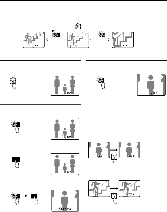
VIEWING CAMERA IMAGES
 Viewing a single-screen image
4
STILL |
ZOOM |
Still image |
Single-screen |
Zoom |
Setting the camera image to single-screen display
1 Press a camera select button (example: 2).
The camera 2 image appears as a single-screen.
2
Pausing images
1 Press the STILL button.
The image will be paused.
 STILL
STILL
2 To cancel the still image, press the STILL button once more.
Pausing will be canceled and normal images will appear.

 STILL
STILL
Note: If you press the ZOOM button while the image is paused, the still image will be enlarged. To return to the original still image, press the ZOOM button once more.
|
|
|
STILL |
|
ZOOM |
|||
|
|
|
||||||
|
|
|
|
|
|
|
|
|
|
|
|
|
|
|
|
|
|
Enlarging images
1 Press the ZOOM button.
The images will be enlarged.
ZOOM
Note: If you set a zoom frame, the area of the image inside the zoom frame will be enlarged. (See page 15.)
If you press the camera select button while zooming, the image will be easier to see due to the movement of the subject. The following changes will occur if you press the camera select button repeatedly.
•An image with little movement (almost a still image)
Large subjects become clearer and moving subjects appear a little rough.
|
2 |
Enlarged image is a |
Subject becomes |
little rough |
clearer |
•An image with large movement (normal viewing)
The image of a moving subject becomes clearer and subjects with little movement appear a little rough.
|
4 |
Enlarged image is a |
Subject becomes |
little rough |
clearer |
Note: If you press some other camera select button while zooming is in progress, the zooming will be canceled and the display will change to a single-screen image for the selected button.
14 |
English |
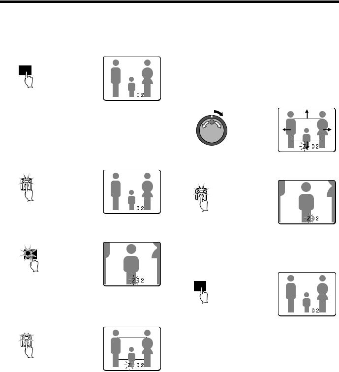
VIEWING CAMERA IMAGES
2 To return an enlarged image to normal image display, press the ZOOM button once more.
The zoom will be canceled and normal images will appear.
ZOOM
Example: To zoom in on the camera 2 image and move the zoom frame
You can select the zoom position by means of the zoom frame which appears on the screen. The zoom frame is set initially at the middle of the screen.
1 Press camera select button 2.
The camera 2 image will appear in a single-screen display.
2
2 Press the ZOOM button.
The images will be enlarged.
ZOOM
3 Press and hold camera select button 2 for about 3 seconds or more.
The zoom will be canceled and the normal image will appear, and the zoom frame (G) will appear on the screen.
 2
2
Note: If the zoom frame remains on the screen for about 10 seconds without being adjusted, the screen will return to zoom display. To make the zoom frame reappear, press and hold camera select button 2 again for 3 seconds or more.
4 Move the zoom frame to the section of the image to be enlarged.
•If you turn the jog dial clockwise, the zoom frame will move to the right. If you turn it counterclockwise, the zoom frame will move to the left.
•If you turn the shuttle dial clockwise, the movement direction changes to vertical movement. If you then turn the jog dial clockwise, the zoom frame will move down, and if you turn it counterclockwise, the zoom frame will move up.
Move the zoom frame to the section of the image to be enlarged.
5 Press camera select button 2 once more.
The image in the repositioned zoom frame will be enlarged.
2
Note: If you press the STILL button while the images are being zoomed, an enlarged still image will be displayed.
6 To return an enlarged image to normal image display, press the ZOOM button once more.
The zoom will be canceled and normal images will appear.
ZOOM
English |
15 |
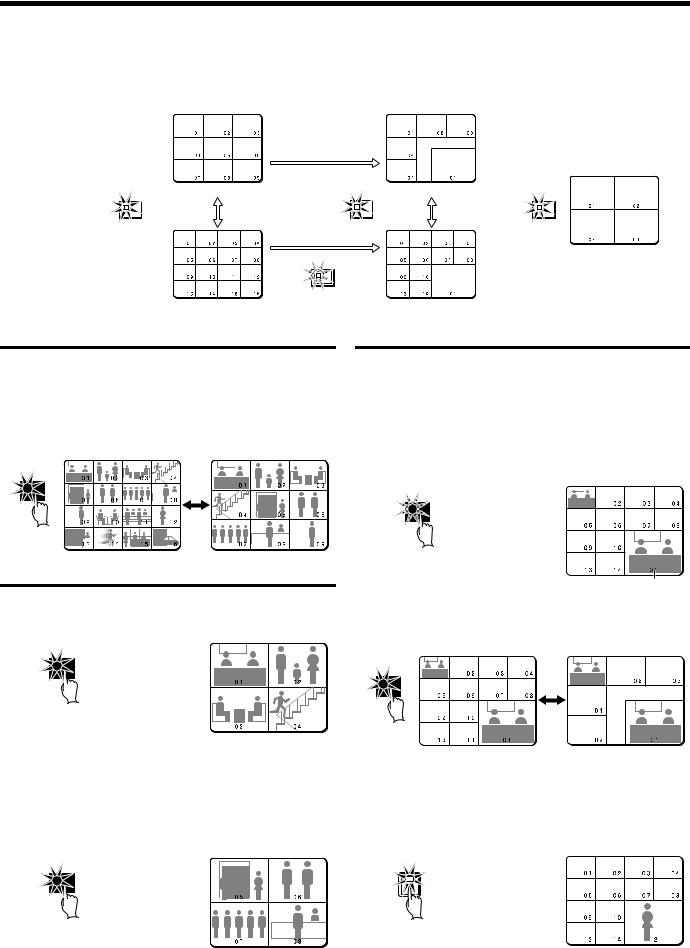
VIEWING CAMERA IMAGES
 Viewing multiple-screen images
Images from the cameras that are connected to the digital video recorder can be displayed in several split-screen formats. Furthermore, the images from each camera can be displayed in any position within the split screen. (See page 81.)
MULTI |
9-screen display |
MULTI |
6-screen display |
QUAD |
||||||
|
|
|||||||||
|
|
|
|
|
|
|
|
|
|
|
|
|
|
|
|
|
|
|
|
|
|
4-screen display
PLUS
16-screen display |
13-screen display |
Viewing images as 9-screen or 16-screen displays
1 Press the MULTI button.
The display switches between 9-screen and 16-screen displays each time the MULTI button is pressed.
To return to a single-screen display, press a camera select button. For the DSR-3009 model, only the 9-screen display is available with no switching.
MULT
Viewing images as a 4-screen display
1 Press the QUAD button.
Images appear as a 4-screen display.
QUAD
2 Press the QUAD button once more.
Camera images are switched in 4-screen display units (1 – 4, 5 – 8, 9 – 12, 13 – 16) each time the button is pressed.
To return to a single-screen display, press a camera select button. For the DSR-3009 model, a 4-screen display of images from cameras 1 – 4, 5 – 8, or 9 – 3 will appear each time the button is pressed.
QUAD
Plus screen viewing
The plus screen allows you to display the images from each camera as a quarter-screen display in the lower right corner of the split-screen display. In addition, images being recorded can be played back in the same position.
1 Press the PLUS button.
The display changes to show a 13-screen display with a plus screen as a quarter-screen picture in the lower-right corner. For the DSR-3009 model, a 6-screen display appears.
PLUS
Plus screen
2 Press the MULTI button.
The display switches between 13-screen and 6-screen each time the MULTI button is pressed.
MULT
3 Press a camera select button (example: 12).
The images from the selected camera will be displayed in the plus screen. To cancel the plus screen, press the PLUS button once more.
For the DSR-3009 model, press a camera select button numbered 9 or less.
12
16 |
English |
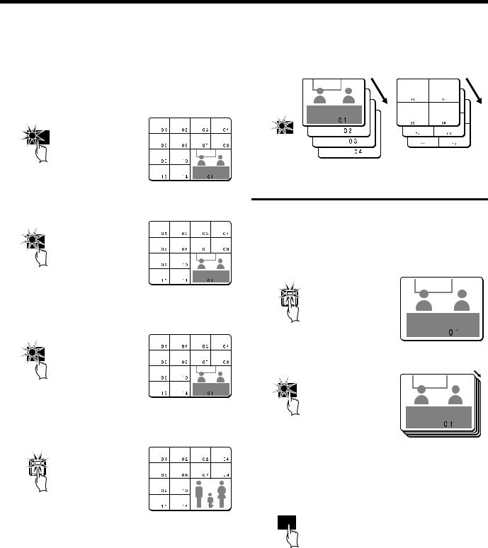
VIEWING CAMERA IMAGES
Example: To display images from camera 2 in the plus screen
Record the images on the hard disk beforehand. (See page 20.)
1 Press the PLAY/STOP button.
All screens will start playing back.
 PLAY/STOP
2 Press the PLUS button.
The plus screen is displayed.
PLUS
3 Press the PLUS button once more.
The plus screen continues to show the playback images, and the other split-screen displays show images in monitoring mode.
PLUS
4 Press camera select button 2.
The plus screen changes to show the images being recorded by camera 2.
2
Note:
•See page 20, 24 for further details on recording and playback.
•To stop playback, press the PLAY/STOP button once more. The display returns to the plus screen.
 Viewing automatically switching images
The camera images are switched automatically in the order that has been set using the SEQUENCE settings. (See page 82.)
SEQUENCE
Automatic switching of Automatic switching of 4-screen display single-screen display
Automatically switching of the single-screen images
1 Switch to single-screen display, and then press the camera select buttons to select the camera for automatic switching (example: 1).
The camera select buttons for the cameras that were selected are stored in memory.
The indicator will illuminate when the next button is pressed.
1
2 Press the SEQUENCE button.
SEQUENCE
3 To cancel automatic switching, press the SEQUENCE button once more, or press one of the individual camera select buttons.
Automatic switching will be canceled and normal images will appear.
SEQUENCE
English |
17 |
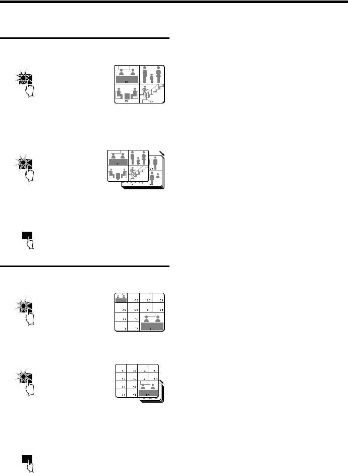
VIEWING CAMERA IMAGES
Automatically switching of the 4-screen images
1 Press the QUAD button.
Images appear as a 4-screen display.
QUAD
2 Press the SEQUENCE button.
Camera images will be switched automatically in 4-screen display units (1 – 4, 5 – 8, 9 – 12, 13 – 16).
For the DSR-3009 model, images from cameras 1 – 4, 5 – 8, or 9 – 3 will be switched automatically.
SEQUENCE
3 Press the SEQUENCE button once more to return to the 4-screen display.
Automatic switching will be canceled and 4-screen display will be restored.
SEQUENCE
Automatically switching of the plus screen image
1 Press the PLUS button.
The plus screen is displayed.
PLUS
2 Press the SEQUENCE button.
The camera images in the plus screen will be switched automatically.
SEQUENCE
3 Press the SEQUENCE button once more to return to the plus screen.
Automatic switching will be canceled and the plus screen will appear.
To cancel the plus screen, press the PLUS button once more.
SEQUENCE
18 |
English |
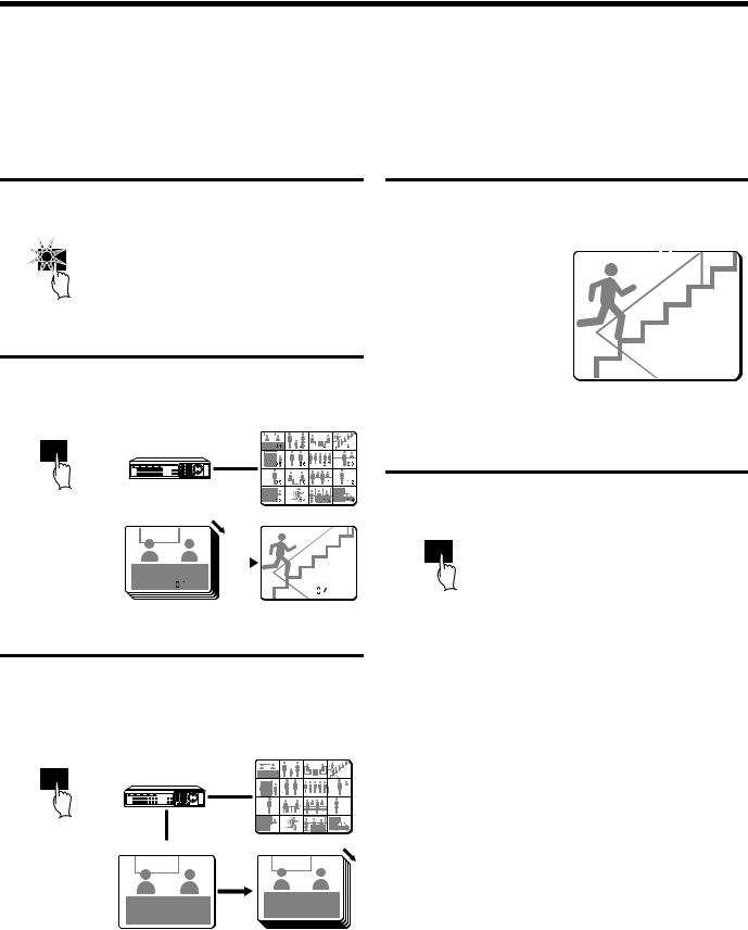
VIEWING CAMERA IMAGES
 Using two monitors for monitoring
If you connect a monitor to the MON2 output terminal on the rear panel, you can display the images from each camera as single-screen images or show an automatic switching screen on monitor 2, even while the main monitor is showing a split-screen display. In addition, the camera images can be shown in a single-screen display during playback, and when an alarm occurs, the alarm camera images can be automatically sent to monitor 2. The default setting is automatic switching of a single screen.
Operating monitor 2
Press the MON2 button.
The MON2 indicator Lights.
MON2
Displaying single-screen camera 4 images on monitor 2
Press camera select button 4.
The images from camera 4 appear on monitor 2 in a single-screen display.
Main monitor
SEQUENCE
|
|
|
|
|
|
|
|
|
|
|
|
|
|
|
|
|
|
|
|
|
|
|
|
|
|
|
|
|
|
|
|
|
|
|
|
Monitor 2 |
|
|
|
Monitor 2 |
||||
|
|
|
|
|
|
|
|
|
|
|
|
|
|
|
|
|
|
|
|
|
|
|
|
|
|
|
|
|
|
|
|
|
|
|
|
|
|
|
|
|
|
|
|
|
|
|
|
|
|
|
|
|
|
Displaying single-screen alarm images on monitor 2
When an alarm is received, the alarm images will be displayed on monitor 2 as single-screen images.
External |
|
|
|
Camera |
|||
alarm |
|
|
number |
||||
|
|
|
|
|
|
|
|
|
|
|
|
|
|
|
|
|
|
|
EA 04 |
|
|
||
|
|
|
EN |
16-06-02 11:18:13 |
|||
|
|
|
|
|
|
|
|
|
|
|
|
|
|
|
|
|
|
|
|
|
|
|
|
|
|
|
|
|
|
|
|
|
|
|
|
|
|
|
|
Note: If alarm images are being displayed on monitor 2, change the “MON.2 DISPLAY” setting in the (ALARM OPERATION SET) menu to “ON”. (See page 66.)
Canceling monitor 2 display
Press the MON2 button once more.
The MON2 indicator switches off.
MON2
Changing monitor 2 from single-screen display to automatic switching
Press the SEQUENCE button.
The camera images being displayed on monitor 2 will switch automatically.
To cancel automatic switching, press the SEQUENCE button once more.
Main monitor |
|
||
SEQUENCE |
|
|
|
|
|
|
|
|
|
|
|
|
|
|
|
|
|
|
|
Monitor 2 |
Monitor 2 |
English |
19 |
RECORDING IMAGES IN THE
NORMAL RECORDING AREA
 Normal recording
Images can be recorded in the normal recording area while they are being monitored.
If the time has not been set, the digital video recorder cannot make recordings. Be sure to set the time. (See page 44.)
 Monitored images are recorded.
1 Setting the time
Press the MENU button to display the LANGUAGE/CLOCK SET menu, and set the date and time. After the setting has been made, press the EXIT/OSD button, the date and time appear in the operating display. (See page 44.)
MENU |
<LANGUAGE/LANGUE/IDIOMA> |
|||||
|
|
|
|
ENGLISH |
|
|
|
|
|
|
|
||
|
|
|
|
<CLOCK |
SET> |
|
|
|
|
01-01-2002 TUE 00:00:00 |
|||
|
|
|
<DAYLIGHT |
SAVING> |
|
|
|
|
|
MODE |
: |
USE |
|
|
|
|
|
WEEK |
MONTH |
TIME |
|
|
|
ON |
1ST-SUN |
04 |
02:00 |
|
|
|
OFF |
LST-SUN |
10 |
02:00 |
|
|
|
|
<EXT.CLOCK SET> |
|
|
|
|
|
ADJUST.TIME |
01:00 |
||
3 Press and hold the REC/STOP button for 3 seconds or more.
The “REC” in the operating display disappears and recording stops.
 REC/STOP
Orange → Off
Note: If the “PROGRAM REC SET” setting is set in the menu screen, program recording of the images for each camera will be possible. (See page 55.)
2 Press the REC/STOP button.
“REC” appears in the operating display and the images being monitored are recorded in the normal recording area. Recording onto the hard disk proceeds automatically (default setting) according to the following settings. The settings can be changed between long-period recording and high-quality recording in five steps. (See page 55.)
•Hard disk recording areas: Normal recording area: 80% Alarm recording area: 19% Archive area: 1%
•Picture quality: EN (Enhanced)
•Recording speed: 10 FPS (67H)
REC/STOP |
|
01 |
REC |
REPEAT EN |
10-27-02 10:48:38 |
Note: Playback is possible during recording. When the PLAY/STOP button is pressed during recording, “c” appears in the operating display and images are played back from the point where recording began.
01
EN |
10-26-02 11:02:28 |
Recording start time
20 |
English |
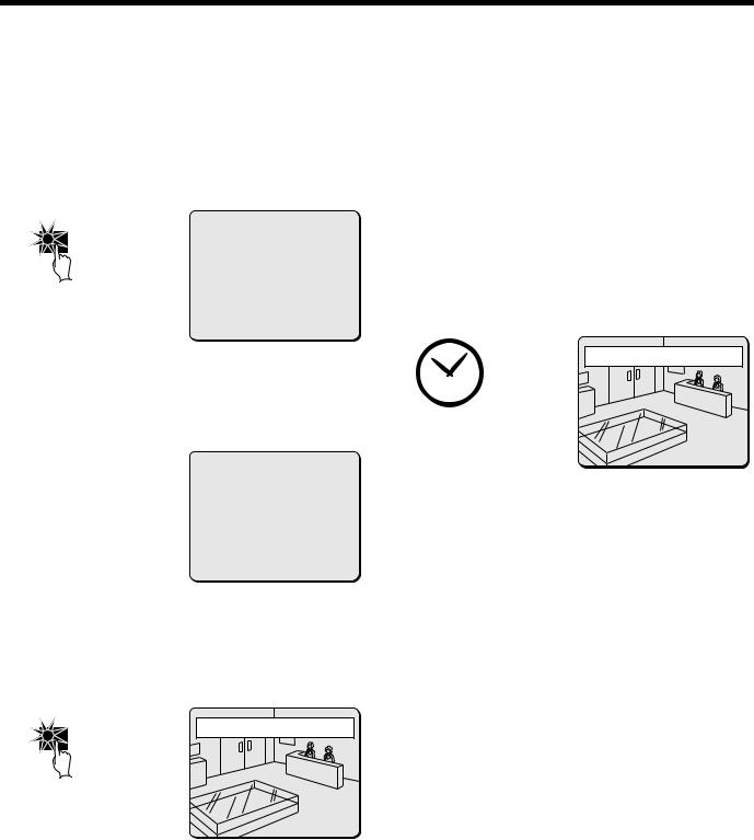
RECORDING IMAGES IN THE NORMAL RECORDING AREA
 Timer recording
The monitored images can be recorded automatically by setting start and end times for each day of the week.
1 1 Setting the time
Press the MENU button to display the LANGUAGE/CLOCK SET menu, and set the date and time. After the setting has been made, press the EXIT/OSD button, the date and time appear in the operating display. (See page 44.)
MENU |
<LANGUAGE/LANGUE/IDIOMA> |
|||||
|
|
|
|
ENGLISH |
|
|
|
|
|
|
|
||
|
|
|
|
<CLOCK |
SET> |
|
|
|
|
01-01-2002 TUE 00:00:00 |
|||
|
|
|
<DAYLIGHT |
SAVING> |
|
|
|
|
|
MODE |
: |
USE |
|
|
|
|
|
WEEK |
MONTH |
TIME |
|
|
|
ON |
1ST-SUN |
04 |
02:00 |
|
|
|
OFF |
LST-SUN |
10 |
02:00 |
|
|
|
|
<EXT.CLOCK SET> |
|
|
|
|
|
ADJUST.TIME |
01:00 |
||
2 Set the timer.
•Press the MENU button to display the TIMER SET menu, and then set the start and end times for timer recording. (See page 56.)
•Once the setting is complete, press the EXIT/OSD button to return to the normal screen.
|
|
<TIMER SET> |
|
|
|
WEEK |
START |
STOP |
PROGRAM |
FPS |
SET |
SUN |
--:-- |
--:-- |
OFF |
10FPS |
OFF |
MON |
08:00 |
18:00 |
OFF |
10FPS |
ON |
THE |
08:00 |
18:00 |
OFF |
10FPS |
ON |
WED |
08:00 |
18:00 |
OFF |
10FPS |
ON |
THU |
08:00 |
18:00 |
OFF |
10FPS |
ON |
FRI |
08:00 |
18:00 |
OFF |
10FPS |
OFF |
SAT |
--:-- |
--:-- |
-- |
10FPS |
OFF |
DLY |
--:-- |
--:-- |
-- |
10FPS |
OFF |
Note: If the “PROGRAM REC SET” setting is set in the menu screen, program recording of the images for each camera will be possible. (See page 55.)
3 Timer recording starts when the timer setting time is reached.
“REC” appears in the operating display and the images being monitored are recorded in the normal recording area. Recording onto the hard disk proceeds automatically (default setting) according to the following settings. The settings can be changed between long-period recording and high-quality recording in five steps. (See page 54.)
•Hard disk recording areas: Normal recording area: 80% Alarm recording area: 19% Archive area: 1%
•Picture quality: EN (Enhanced)
•Recording speed: 10 FPS (67H)
01
REC |
REPEAT EN |
05-10-02 19:30:00 |
Note: Playback is possible during recording. When the PLAY/STOP button is pressed during recording, c appears in the operating display and images are played back from the point where recording began.
4 Timer recording stops when the set end time is reached.
The TIMER indicator swithes off and the recording symbol (REC) disappears from the operating display and recording stops.
Note: Press the TIMER button to stop timer recording. Timer recording then stops.
2 Press the TIMER button.
The TIMER indicator illuminates and the digital video recorder switches to timer recording standby mode.
TIMER |
01 |
|
EN |
05-10-02 17:30:25 |
Note:
•If SET in the TIMER SET menu is not set to “ON”, or if the timer settings are not made correctly, an alarm will sound when the TIMER button is pressed.
•
•
•
The TIMER indicator illuminates when the timer setting has been made correctly.
When the timer setting time is reached, the TIMER indicator and the REC indicator illuminate and timer recording starts.
If you press the TIMER button during timer recording, the TIMER indicator and the REC indicator switch off and timer recording stops.
English |
21 |
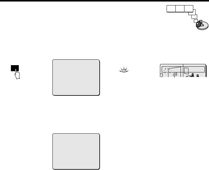
RECORDING IMAGES IN THE ALARM RECORDING AREA
 Alarm recording
1 1 Setting the time 2 Suspicious person detection
Alarm images are recorded
Press the MENU button to display the LANGUAGE/CLOCK SET menu, and set the date and time. After the setting has been made, press the EXIT/OSD button, the date and time appear in the operating display. (See page 44.)
MENU |
<LANGUAGE/LANGUE/IDIOMA> |
|||||
|
|
|
|
ENGLISH |
|
|
|
|
|
|
|
||
|
|
|
|
<CLOCK |
SET> |
|
|
|
|
01-01-2002 TUE 00:00:00 |
|||
|
|
|
<DAYLIGHT |
SAVING> |
|
|
|
|
|
MODE |
: |
USE |
|
|
|
|
|
WEEK |
MONTH |
TIME |
|
|
|
ON |
1ST-SUN |
04 |
02:00 |
|
|
|
OFF |
LST-SUN |
10 |
02:00 |
|
|
|
|
<EXT.CLOCK SET> |
|
|
|
|
|
ADJUST.TIME |
01:00 |
||
2 Set alarm recording.
•Press the MENU button to display the ALARM REC MODE SET menu in the menu screen. Then change the ALARM RECORDING setting to the desired alarm recording setting (ENABLED, AL-REC ON TIMER, AL-REC OFF TIMER or OLY AL-REC ON TMR) and change the ALARM TRIGGER setting. (See page 59.)
•Press the EXIT/OSD button to return to the normal screen.
|
<ALARM REC MODE SET> |
|||
PICTURE QUALITY |
: |
SUPER FINE |
||
AUDIO |
RECORDING |
: |
ON |
|
ALARM |
RECORDING |
: |
ENABLED |
|
ALARM |
INTERLEAVE |
: |
ONLY |
|
PROGRAM GROUP |
|
: |
OFF |
|
REC |
RATE: @ |
0.1FPS, |
|
DURATION: 40SEC |
PRE-ALARM RECORDING |
: |
ON |
||
REC |
RATE:@ |
*** FPS, |
|
DURATION: *** |
=> |
(01010 ALARMS CAN BE RECORDED ) |
|||
ALARM |
TRIGGER |
|
: |
ALARM |
When an alarm occurs, “ALARM” appears in the operating display, the ALARM indicator flashes and alarm recording (REC symbol) starts. Alarm images are recorded in the alarm recording area. Furthermore, the number of alarms in the operating display is increased by one each time an alarm occurs.
SA |
01 |
REC ALARM 0001 REPEAT EN |
05-10-02 18:10:25 |
ALARM
The number of alarms is counted.
Note:
•Normal recording and timer recording stop when an alarm occurs during normal recording or timer recording.
•In order to record more than 16,000 alarm events (if there is a single built in hard disk; 32,000 events if two built in hard disks are being used and mirroring is off), set the normal recording area to 0%.
This will allow the alarm recording area to be the maximum size available for alarm recordings to be carried out.
The number of alarm events that can be recorded is displayed in the alarm recording setting screen.
If the number of events that can be recorded exceeds 100,000, then “99999” is displayed. This number is a guide. If an alarm occurs while the previous alarm is still being recorded, the alarm duration will be extended, and so that actual number of alarms recorded may be less than the number displayed.
In addition, if the size of the normal recording area is set to 0%, “ALARM SEARCH”, “ALARM THUMBNAIL SEARCH” and “MOTION DETECTOR SEARCH” cannot be used. In this case, use “TIME/DATE SEARCH” instead. Furthermore, the ALARM SKIP function also will not operate, so you should use the fast forward and fast rewind functions instead.
3 Ending alarm recording
After the end of the alarm duration period (default setting: 5 sec), the “REC” and “ALARM” displays stop flashing and recording stops.
22 |
English |
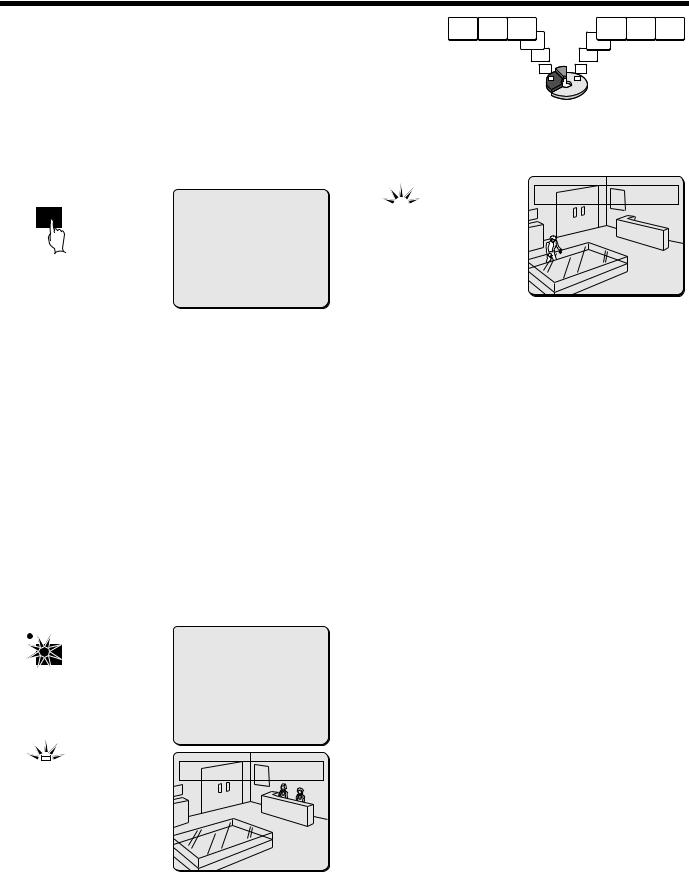
RECORDING IMAGES IN THE ALARM RECORDING AREA
 Pre-alarm recording
Pre-alarm images |
Monitored images |
are recorded |
are recorded |
1 Setting the time
Press the MENU button to display the LANGUAGE/CLOCK SET menu, and set the date and time. After the setting has been made, press the EXIT/OSD button, the date and time appear in the operating display. (See page 44.)
3 When an alarm is received, pre-alarm recording stops automatically and the alarm images are recorded.
The “PRE” disappears from the operating display, “ALARM” flashes and the ALARM indicator flashes.
MENU |
<LANGUAGE/LANGUE/IDIOMA> |
|
|
|
|
|||||
|
|
|
|
ENGLISH |
ALARM |
|||||
|
|
|
|
|||||||
|
|
|
|
<CLOCK |
SET> |
|
|
|
|
|
|
|
|
01-01-2002 TUE 00:00:00 |
|||||||
|
|
|
<DAYLIGHT |
SAVING> |
|
|
|
|
|
|
|
|
|
MODE |
: |
USE |
|
|
|
|
|
|
|
|
|
WEEK |
MONTH |
TIME |
||||
|
|
|
ON |
1ST-SUN |
04 |
02:00 |
|
|
|
|
|
|
|
OFF |
LST-SUN |
10 |
02:00 |
|
|
|
|
|
|
|
|
<EXT.CLOCK SET> |
|
|
|
|
|
|
|
|
|
ADJUST.TIME |
01:00 |
|
|
|
|
||
|
SA |
01 |
REC ALARM 0001 REPEAT EN |
06-10-02 09:30:15 |
|
|
|
|
2 Set pre-alarm recording.
Press the MENU button to display the ALARM REC MODE SET menu. Set ALARM RECORDING to the desired alarm recording setting (example: ENABLED). The *** setting for PRE-ALARM RECORDING will be set to “OFF”, so change it to “ON”. (See page 62.)
Press the EXIT/OSD button to return to the normal screen. “PRE” appears in the operating display, the ALARM indicator illuminates and pre-alarm recording starts (the REC mark does not appear).
The same monitored image as in the normal recording area is recorded repeatedly in the alarm recording area.
Recording onto the hard disk proceeds automatically (default setting) according to the following settings. The settings can be changed between long-period recording and high-quality recording in five steps. (See page 59.)
•Hard disk recording areas: Normal recording area: 80% Alarm recording area: 19% Archive area: 1%
•Picture quality: EN (Enhanced)
•Recording speed: 10 FPS (67H)
REC/STOP |
<ALARM REC MODE SET> |
|||||
|
|
PICTURE QUALITY |
: |
SUPER FINE |
||
|
|
|||||
|
|
AUDIO RECORDING |
: |
ON |
||
|
|
ALARM RECORDING |
: |
ENABLED |
||
|
|
ALARM INTERLEAVE |
: |
ONLY |
||
|
|
PROGRAM GROUP |
|
: |
OFF |
|
|
|
REC RATE: @ |
0.1FPS, |
|
DURATION: 40SEC |
|
|
|
PRE-ALARM RECORDING |
: |
ON |
||
|
|
REC RATE:@ |
*** FPS, |
|
DURATION: *** |
|
=> |
(01010 ALARMS CAN BE RECORDED ) |
|||||
|
|
ALARM TRIGGER |
|
: |
ALARM |
|
ALARM |
|
01 |
|
|
REC PRE |
0000 REPEAT EN 05-10-02 18:10:25 |
|
|
|
|
|
English |
23 |
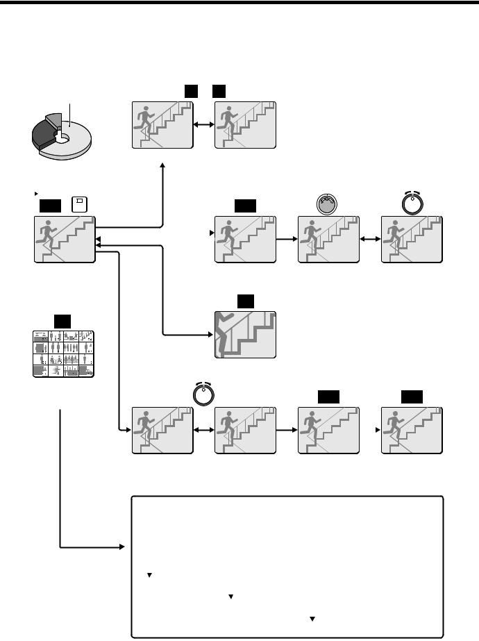
PLAYING BACK RECORDED IMAGES
The digital video recorder can play back recorded images in the normal recording area (normal recording, timer recording).
 Playback operations

 ALARM
ALARM 

Normal recording area
bSkipping to the previous or next alarm
PLAY/STOP |
4 |
|
|
|
|
|
|
|
|
|
|
STILL |
||||||||||
|
|
|||||||||||||||||||||
|
|
|||||||||||||||||||||
|
|
|
|
|
|
|
|
|
|
|
|
|
|
|
|
|
|
|
|
|
|
|
|
|
|
|
|
|
|
|
|
|
|
|
|
|
|
|
|
|
|
|
|
|
|
|
|
|
|
|
|
|
|
|
|
|
|
|
|
|
|
|
|
|
|
|
|
|
|
|
|
|
|
|
|
|
|
|
|
|
|
|
|
|
|
|
|
|
|
|
|
|
|
|
|
|
|
|
|
|
|
|
|
|
|
|
|
|
|
|
|
|
|
|
|
|
|
|
|
|
|
|
|
|
|
|
|
|
|
|
|
|
|
|
|
|
|
|
|
|
|
|
|
|
|
|
|
|
|
|
|
|
|
|
|
|
|
|
|
|
bPlayback in a single screen (See page 25.)
MULT
bPlayback in multiscreen display (See page 27.)
bStill image |
bFrame advance |
b Slow playback |
||
(See page 26.) |
(forward/reverse) |
and fast |
||
ZOOM |
(See page 26.) |
forward/fast |
||
|
rewind playback |
|||
|
|
|
|
|
|
|
|
|
(See page 25.) |
bZooming images (See page 26.)
SHUTTLE HOLD |
|
|
SHUTTLE HOLD |
||||||||
|
|
|
|
|
|
|
|
|
|
|
|
|
|
|
|
|
|
|
|
|
|
|
|
|
|
|
|
|
|
|
|
|
|
|
|
|
|
|
|
|
|
|
|
|
|
|
|
|
|
|
|
|
|
|
|
|
|
|
|
|
|
|
|
|
|
|
|
|
|
|
|
|
|
|
|
|
|
|
|
|
|
|
|
|
|
|
|
|
|
|
|
|
|
|
|
|
Fast forward/fast rewind and reverse |
|
Locking speed for |
|
Releasing speed |
|
playback (See page 25.) |
|
|
||
|
|
fast forward/rewind |
|
lock |
|
|
|
|
|
||
|
|
|
playback |
|
|
|
|
|
(See page 25.) |
|
|
Normal playback
•When playing back recordings for the first time:
The recorded images will be played back from the beginning.
•When playing back for the second or subsequent time:
Playback will start from the point where the last playback session ended.
(Starting point for |
|
|
|
first playback) |
Ending point |
|
|
|
(Starting point for |
|
|
|
|
|
|
|
second playback) |
Ending point |
|
|
|
(Starting point for |
|
|
|
|
|
|
|
|
|
|
|
third playback) |
Ending point |
|
|
|
|
|
|
|
|
24 |
English |
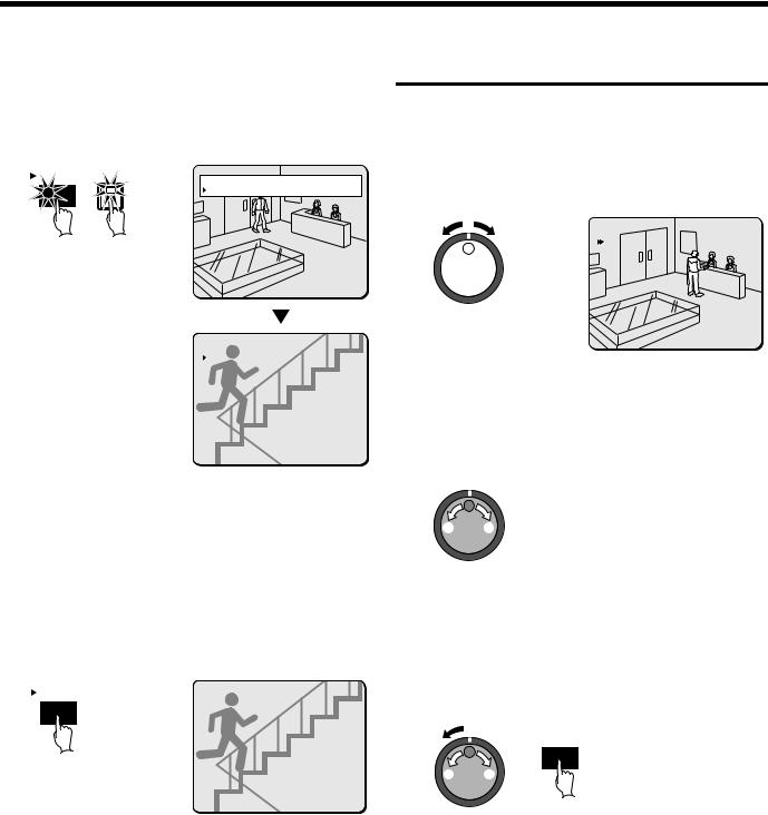
PLAYING BACK RECORDED IMAGES
 Playback in a single screen
1 Press the PLAY/STOP button.
cappears in the operating display and the images recorded in the normal recording area are played back. You can press the camera select buttons to select the camera images to be played back.
PLAY/STOP |
4 |
01 |
EN |
10-26-02 11:02:50 |
|
04 |
EN |
10-27-02 13:38:33 |
Note:
•Image playback starts from the point (time) that the recording started.
If there is no starting position, or if a reset has been made, the oldest recorded image is played back.
•When playback is finished, playback mode is automatically paused. The pause (h) symbol appears in the operating display and the STILL indicator illuminates.
•If playback has been carried out at least once, playback will start from the position where the last playback session ended.
2 Press the PLAY/STOP button again.
Playback stops.
PLAY/STOP |
04 |
EN |
11-20-02 04:00:00 |
Fast forward/fast rewind and reverse playback
1 Turn the shuttle dial clockwise (or counterclockwise) during playback.
When the shuttle dial is turned clockwise, eappears in the operating display and fast forward playback starts. If it is turned counterclockwise, fappears in the operating display and rewind playback starts.
When you release the shuttle dial, normal playback resumes.
01
EN |
11-17-02 02:38:00 |
Note: Fast-forwarding operates at a speed of up to 70 times normal playback speed, and rewinding operates at up to 50 times normal playback speed. The actual speed will vary depending on recording conditions such as recording quality.
2 Changing the playback speed
(Fast forward/slow playback)
 3
3
22
1Turn the jog dial clockwise.
Fast forward playback starts and eappears in the operating display.
2Turn the jog dial counterclockwise.
Slow playback starts and hcappears in the operating display.
3Return to normal playback.
Turn the jog dial clockwise. cappears in the operating display.
(Fast rewind playback)
1 |
SHUTTLE HOLD |
|
|
2 |
|
43
Note: If playback is started just as recording is being carried out, recording will have priority, so that the playback images may be paused momentarily.
1Turn the shuttle dial counterclockwise slightly (fix at fast rewind) dwill be displayed, so press the SHUTTLE HOLD button. The SHUTTLE HOLD indicator will illuminate and the rewind playback speed will be fixed at the current speed.
2Turn the shuttle dial counterclockwise again.
The speed becomes faster than for normal rewind playback, and fappears in the operating display.
3Turn the jog dial clockwise.
eappears in the operating display.
4Return to normal playback.
Turn the jog dial counterclockwise. cappears in the operating display.
English |
25 |
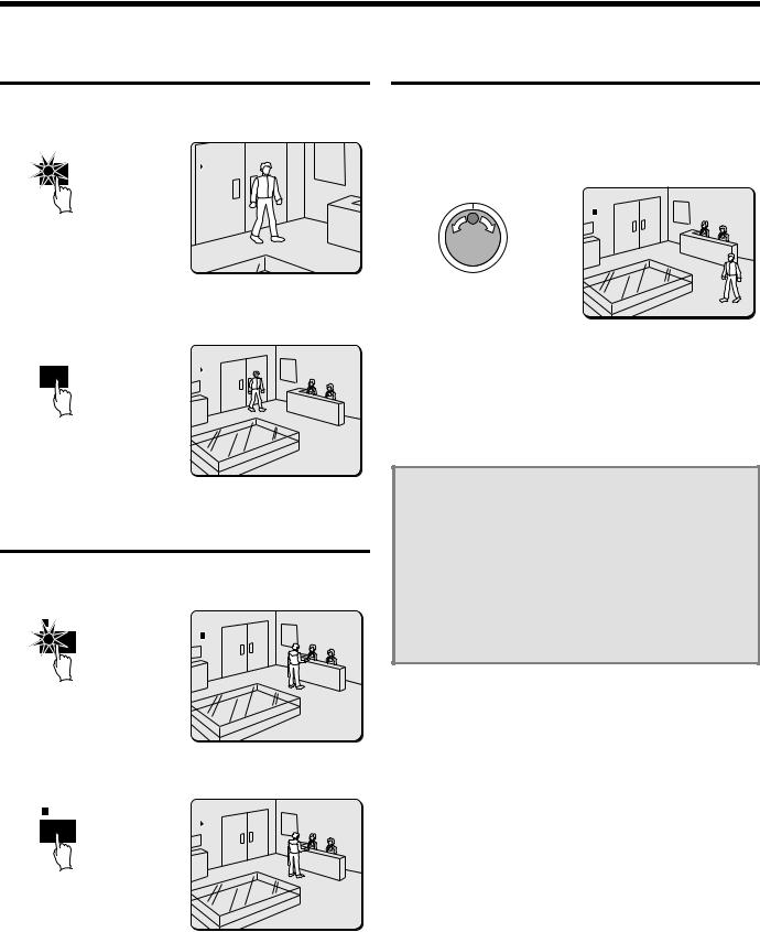
PLAYING BACK RECORDED IMAGES
Zooming the image during playback
1 Press the ZOOM button during playback.
The images will be enlarged.
ZOOM |
01 |
EN |
11-17-02 02:36:00 |
2 To return an enlarged image to normal image display, press the ZOOM button once more.
The zoom will be canceled and normal images will appear.
ZOOM |
01 |
EN |
11-17-02 02:36:10 |
Note: You can also change the zoom position. For details on this operation, refer to “Enlarging images” (See page 15).
Viewing still images
1 Press the STILL button during playback.
happears in the operating display and a still image is displayed.
STILL |
01 |
EN |
11-17-02 02:38:00 |
Frame advance (forward/reverse)
1 Turn the jog dial clockwise (or counterclockwise) in still mode.
Turn the jog dial clockwise to advance the still image by one frame (one field).
Turn it counterclockwise to rewind the still image by one frame (one field).
01
EN |
11-17-02 02:50:08 |
Note: If the jog dial is turned quickly, the frame feed speed also increases. However, if the speed is too fast, the images will stop. Play back the images at an appropriate speed.
During the following operations the picture may appear distorted or momentarily frozen. This is normal and not a malfunction.
•During the continuous playback from the normal and the alarm recording area, the picture may be distorted when the recording area is switched.
•When playing back during an alarm recording, during continuous playback from the normal and alarm recording area, during normal playback or when using the fast forward/rewind playback the picture may appear momentarily frozen.
2 Press the STILL button once more.
Still mode is canceled.
STILL |
01 |
EN |
11-17-02 02:38:20 |
26 |
English |
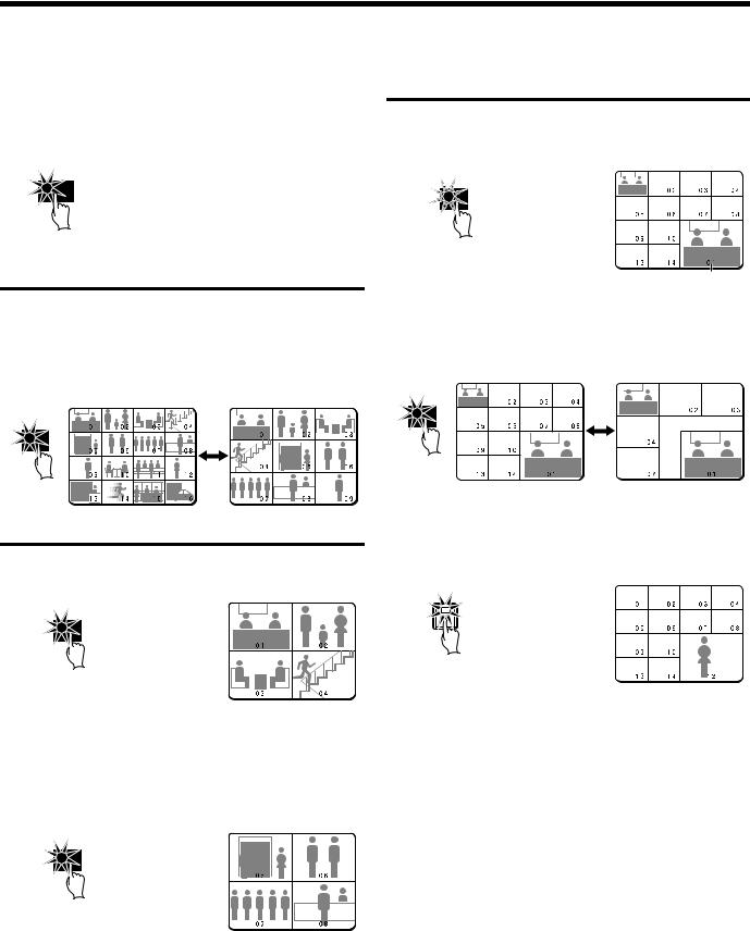
PLAYING BACK RECORDED IMAGES
 Playing back multiple-screen displays
Recorded images can be playback in several split-screen formats. Furthermore, the images from each camera can be displayed in any position within the split-screen. (See page 81.)
1 Press the PLAY/STOP button.
 PLAY/STOP
Playing back images as 9-screen or 16-screen displays
1 Press the MULTI button.
The display switches between 9-screen and 16-screen each time the MULTI button is pressed.
To return to a single-screen display, press a camera select button. For the DSR-3009 model, only the 9-screen display is available with no switching.
MULT
Playing back images as a 4-screen display
1 Press the QUAD button.
Images appear as a 4-screen display.
QUAD
2 Press the QUAD button once more.
Camera images are switched in 4-screen display units (1 – 4, 5 – 8, 9 – 12, 13 – 16) each time the button is pressed.
To return to a single-screen display, press a camera select button. For the DSR-3009 model, a 4-screen display of images from cameras 1 – 4, 5 – 8, or 9 – 3 will appear each time the button is pressed.
QUAD
Playing back images as 13-screen or 6-screen displays (plus screen)
1 Press the PLUS button.
The display changes to show a 13-screen or 6-screen display with a plus screen as a quarter-screen picture in the lower-right corner.
PLUS
Plus screen
2 Press the MULTI button.
The display switches between 13-screen and 6-screen each time the MULTI button is pressed.
For the DSR-3009 model, only the 6-screen display is available with no switching.
MULT
3 Press a camera select button (example: 12).
The playing back images from the selected camera will be displayed in the plus screen.
To cancel the plus screen, press the PLUS button once more. For the DSR-3009 model, press camera select button 9.
12
English |
27 |
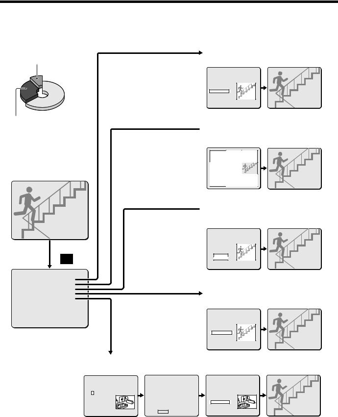
SEARCHING FOR RECORDED IMAGES
Images that have been recorded in the alarm recording area and in the archive area can be played back. Furthermore, images can also be searched for by recording date and time, and you can also search for moving objects that have been detected by a motion sensor during image playback.
|
a Alarm search (See page 29.) |
Archive area |
Alarm image search and playback |
|
|
<ALARM SEARCH> |
||
NO |
DATE |
TIME |
CH |
TOTAL ALARMS |
0101 |
12-13 |
11:13 16 |
00234 |
|
0102 |
12-13 |
11:15 10 |
|
|
0103 |
12-13 |
15:19 06 |
|
|
0104 |
12-15 |
10:13 01 |
|
|
0105 |
12-16 |
16:13 03 |
SEARCHING |
|
0106 |
12-16 |
11:13 12 |
|
|
0107 |
12-19 |
14:23 10 |
|
|
0108 |
12-20 |
05:37 04 |
|
|
|
MOVE:JOG |
|
SELECT:SHUTTLE |
|
Preview display |
Single-screen display |
Alarm recording area
 a Alarm image thumbnail search (See page 30.)
Alarm image thumbnail search and playback
SEARCH
|
<SEARCH> |
|
ALARM SEARCH |
-> |
|
ALARM THUMBNAIL SEARCH |
-> |
|
TIME/DATE SEARCH |
-> |
|
ARCHIVE AREA SEARCH |
-> |
|
MOTION DETECTION SEARCH |
-> |
|
MOVE:JOG |
SELECT:SHUTTLE |
|
0101 |
0102 |
0103 |
0104 |
0105 |
0106 |
0107 |
0108 |
0109 |
Thumbnail display |
Single-screen display |
 a Time/date search (See page 30.)
Searching and playing back recorded images by date/time
|
<TIME/DATE SEARCH> |
|
||
RECORDING TOP |
: |
12-15-00 08:00 |
||
RECORDING END |
: |
12-22-00 |
17:00 |
|
CHANNEL : -- |
|
|
|
|
SEARCH : |
|
|
|
|
DATE |
TIME |
|
|
|
12-20-00 05:37 |
|
|
SEARCHING |
|
PREVIEW |
-> |
|
|
|
VIEW |
-> |
|
|
|
CHANGE:JOG |
|
SET:SHUTTLE |
||
Preview display |
Single-screen display |
a Archive area search (See page 31.)
Playing back images saved (copied) in the archive area
|
|
<ARCHIVE AREA SEARCH> |
|
|||
NO |
DATE |
TIME |
CH |
CAPACITY |
||
0011 12-13 |
11:13 01 |
TOTAL |
- |
1024MB |
||
0012 12-13 |
11:15 01 |
USED |
- |
400MB |
||
0013 12-13 |
15:19 01 |
|
|
|
||
0014 12-15 |
10:13 01 |
|
|
|
||
0015 12-16 |
16:13 01 |
|
SEARCHING |
|||
0016 12-16 |
11:13 01 |
|
|
|
||
0017 12-19 |
14:23 01 |
|
|
|
||
0018 12-20 |
05:37 01 |
|
|
|
||
|
MOVE:JOG |
|
SELECT:SHUTTLE |
|||
Preview display |
Single-screen display |
a Motion detection search (See page 32.)
Searching for and playing back moving objects detected by a motion sensor
<MOTION DETECTION SEARCH>
SEARCH FROM : NORMAL / CHANNEL : 4
START : |
|
|
10-28-01 08:00 |
||
END |
: |
|
10-28-01 20:00 |
||
MOTION SENSOR |
-> |
|
PREVIEW |
-> |
|
VIEW |
|
-> |
|
MOVE:JOG |
SELECT:SHUTTLE |
- |
- |
- |
- |
- |
- |
- |
- |
- |
- |
|||
- |
- |
- |
- |
- |
- |
- |
- |
- |
- |
|||
- |
- |
- |
|
|
|
|
|
|
- |
- |
- |
- |
ú |
ú |
ú |
||||||||||
- |
- |
- |
|
|
|
|
|
|
- |
- |
- |
- |
ú |
ú |
ú |
||||||||||
- |
- |
- |
|
|
|
|
|
|
- |
- |
- |
- |
ú |
ú |
ú |
||||||||||
- |
- |
- |
- |
- |
- |
- |
- |
- |
- |
|||
- |
- |
- |
- |
- |
- |
- |
- |
- |
- |
|||
- |
- |
- |
- |
- |
- |
- |
- |
- |
- |
|||
|
|
LEVEL : 6 |
|
|
|
EXIT |
|
|
|
|||
|
<MOTION DETECTION SEARCH> |
||
SEARCH FROM : NORMAL |
/ CHANNEL : 4 |
||
START : |
|
|
|
10-28-01 10:00 |
|
||
END |
: |
|
|
10-28-01 20:00 |
|
||
MOTION SENSOR |
-> |
|
|
PREVIEW |
-> |
|
|
VIEW |
MOVE:JOG |
-> |
SELECT:SHUTTLE |
|
|
||
Date/time search of an image Motion sensor setting |
Preview display |
Single-screen display |
for motion detection |
|
|
28 |
English |
 Loading...