


INSTRUCTION MANUAL
DVD Video Recorder
DRW-500
REMOTE CONTROLLER RB-DRW500
®
TM
TM
SANYO’S HELP-LINE
Call the toll-free number below if you have any difficulties operating this product. 1-800-813-3435 (Weekdays: 7:30 AM - 4:00 PM Central Time)
Please Read This Manual.
We recommend that you read this manual carefully before connecting your DVD Video Recorder and operating it for the first time.
Keep the manual in a safe place for future reference.
1AD6P1P2047--A DRW-500, Issue Number 2 |
English |
|
||
|
|
|
|
|
|
|
|
|
|
|
|
|
|
|
|
|
|
|
|

CONTENTS
Important Safety Instructions ............................................ |
E2 |
Safety Certification ............................................................. |
E4 |
Accessories ......................................................................... |
E4 |
Controls ............................................................................... |
E5 |
Remote Control ................................................................... |
E6 |
For Safe and Efficient Operation ....................................... |
E7 |
Basic Connection ................................................................ |
E8 |
Before Connection ........................................................... |
E8 |
Step 1: Connecting the Antenna Cable ........................... |
E8 |
Step 2: Connecting the Video Cable .............................. |
E11 |
Step 3: Connecting the Audio Cables ............................ |
E12 |
Step 4: Connecting the Power Cord .............................. |
E14 |
Connecting a VCR or Similar Recording Equipment |
|
to This Unit ................................................................. |
E15 |
Connecting to a Satellite Receiver or a Cable Box ....... |
E17 |
Setting the Clock ............................................................... |
E18 |
Preparations .................................................................. |
E18 |
To Set the Clock ............................................................ |
E18 |
Tuner Setting ..................................................................... |
E19 |
Setting “Channel Setup”. ............................................... |
E19 |
Before Initial Setting ......................................................... |
E22 |
Common Procedure ...................................................... |
E22 |
Initial Settings.................................................................... |
E23 |
Recording Setup ............................................................ |
E23 |
Preparations ............................................................... |
E23 |
Setting “Record Mode” ............................................... |
E23 |
Setting “Auto Chapter” ............................................... |
E24 |
DVD Control .................................................................. |
E25 |
Preparations ............................................................... |
E25 |
Setting “Disc Menu” ................................................... |
E25 |
Setting “Angle Mark” .................................................. |
E26 |
Setting “Audio” ........................................................... |
E26 |
Setting “Subtitle” ........................................................ |
E26 |
Setting “Parental Control” .......................................... |
E27 |
General .......................................................................... |
E29 |
Preparations ............................................................... |
E29 |
Setting “Menu Language” .......................................... |
E29 |
Video ............................................................................. |
E30 |
Preparations ............................................................... |
E30 |
Setting “TV Display” ................................................... |
E30 |
Audio ............................................................................. |
E31 |
Preparations ............................................................... |
E31 |
Setting “Digital Out” .................................................... |
E31 |
Setting “DRC (Dynamic Range Control)” ................... |
E31 |
AV Select ....................................................................... |
E32 |
Preparations ............................................................... |
E32 |
Setting “AV1 Select” and “AV2 Select” ....................... |
E32 |
Record Status ................................................................ |
E33 |
Preparations ............................................................... |
E33 |
Setting “Record Time” ................................................ |
E33 |
Setting “Record Day” ................................................. |
E34 |
Setting “Input Source” ................................................ |
E35 |
Setting “TV” ................................................................ |
E35 |
Setting “Record Mode” ............................................... |
E36 |
Setting “Title” .............................................................. |
E36 |
Record List .................................................................... |
E37 |
Disc Information ................................................................ |
E38 |
Recordable Discs .......................................................... |
E38 |
Playable Discs ............................................................... |
E38 |
Recording .......................................................................... |
E40 |
Preparations .................................................................. |
E40 |
Recording TV Programs ................................................ |
E41 |
Timer Recording ............................................................ |
E43 |
Recording from an External Equipment (VCR, etc.) ...... |
E43 |
Disc Playback .................................................................... |
E44 |
Preparations .................................................................. |
E44 |
Basic Playback .............................................................. |
E45 |
Stopping Playback ......................................................... |
E45 |
Selecting a Top Menu .................................................... |
E46 |
Selecting a DVD Menu .................................................. |
E46 |
Chapter (Track) Skip ..................................................... |
E46 |
Title or Chapter Search ................................................. |
E46 |
Time Search .................................................................. |
E46 |
Time Search [CD] .......................................................... |
E47 |
Track Search [CD] ......................................................... |
E47 |
Fast Playback ................................................................ |
E47 |
Slow Motion Playback ................................................... |
E47 |
Still Picture (Pause) ....................................................... |
E47 |
Frame by Frame Advance Playback |
|
[DVD-Video] [DVD+RW] [DVD+R] .............................. |
E47 |
Picture Zoom ................................................................. |
E48 |
Viewing from a Desired Camera Angle |
|
(Multi-Angle) [DVD-Video] .......................................... |
E48 |
Repeat Playback ........................................................... |
E48 |
Designated Range Repeat Playback (A-B Repeat) ...... |
E48 |
Selecting Subtitle Language .......................................... |
E49 |
Selecting Audio Soundtrack Language |
|
(Multi-Language) ........................................................ |
E49 |
Shuffle Playback [CD] ................................................... |
E50 |
Programmed Playback [CD] .......................................... |
E50 |
To Check the Disc Playing Time .................................... |
E50 |
MP3 CD Operation............................................................. |
E51 |
Before Starting .............................................................. |
E51 |
MP3 CD Playback ......................................................... |
E51 |
Stopping Playback ......................................................... |
E51 |
Pause ............................................................................ |
E52 |
File Skip ......................................................................... |
E52 |
Repeat Playback ........................................................... |
E52 |
To Check the Elapsed Playing Time .............................. |
E52 |
Picture Disc Operation ..................................................... |
E53 |
Kodak Picture CD Playback .......................................... |
E53 |
JPEG CD Playback ....................................................... |
E54 |
Picture Zoom ................................................................. |
E54 |
Editing ................................................................................ |
E55 |
Preparations .................................................................. |
E55 |
Play/Edit Titles ............................................................... |
E55 |
Edit Disc ........................................................................ |
E57 |
Troubleshooting Guide ..................................................... |
E59 |
Maintenance ...................................................................... |
E61 |
Specifications .................................................................... |
E61 |
Warranty ............................................................................. |
E62 |
Note:
This handling description is printed prior to product development.
When a part of the product specification must be changed to improve operability or other functions, priority is given to the product specification itself. In such instances, the instruction manual may not entirely match all the functions of the actual product. Therefore, the actual product and packaging, as well as the name and illustration, may differ from the manual.
-E1-
CAUTION
RISK OF ELECTRIC SHOCK
DO NOT OPEN
CAUTION: TO PREVENT THE RISK OF ELECTRIC SHOCK, DO NOT REMOVE COVER (OR BACK).
NO USER-SERVICEABLE PARTS INSIDE.
REFER SERVICING TO QUALIFIED SERVICE PERSONNEL.
This symbol indicates that dangerous voltage constituting a risk of electric shock is present within this unit.
This symbol indicates that there are important operating and maintenance instructions in the literature accompanying this unit.
WARNING: TO PREVENT FIRE OR SHOCK HAZARD, DO NOT EXPOSE THIS APPLIANCE TO RAIN OR MOISTURE.
WARNING: UNAUTHORIZED RECORDING OF COPYRIGHTED MATERIAL MAY VIOLATE APPLICABLE COPYRIGHT LAWS. THE MANUFACTURER ASSUMES NO RESPONSIBILITY FOR UNAUTHORIZED DUPLICATION, USE OR OTHER ACTS WHICH INFRINGE UPON THE RIGHTS OF COPYRIGHT OWNERS.
IMPORTANT SAFETY INSTRUCTIONS
1.Read Instructions – All the safety and operating instructions should be read before the product is operated.
2.Retain Instructions – The safety and operating instructions should be retained for future reference.
3.Heed Warnings – All warnings on the product and in the operating instructions should be adhered to.
4.Follow Instructions – All operating and use instructions should be followed.
5.Cleaning – Unplug this product from the wall outlet before cleaning. Do not use liquid cleaners or aerosol cleaners. Use a damp cloth for cleaning.
6.Attachments – Do not use attachments not recommended by the product manufacturer as they may cause hazards.
7.Water and Moisture – Do not use this product near water – for example, near a bath tub, wash bowl, kitchen sink, or laundry tub; in a wet basement; or near a swimming pool; and the like.
8.Accessories – Do not place this product on an unstable cart, stand, tripod, bracket, or table. The product may fall, causing serious injury to a child or adult, and serious damage to the product. Use only with a cart, stand, tripod bracket, or table recommended by the manufacturer, or sold with the product. Any mounting of the product should follow the manufacturer’s instructions, and should use a mounting accessory recommended by the manufacturer.
9. A product and cart combination |
PORTABLE CART WARNING |
should be moved with care. Quick stops, |
(Symbol provided by RETAC) |
|
|
excessive force, and uneven surfaces |
|
may cause the product and cart |
|
combination to overturn. |
|
10.Ventilation – Slots and openings in the cabinet are provided for ventilation and to ensure reliable operation of the product and to protect it from overheating, and these openings must not be blocked or covered. The openings should never be blocked by placing the product on a bed, sofa, rug, or other similar surface. This product should not be placed in a built-in installation such as a bookcase or rack unless proper ventilation is provided or the manufacturer’s instructions have been adhered to.
11.Power Sources – This product should be operated only from the type of power source indicated on the marking label. If you are not sure of the type of power supply to your home, consult your product dealer or local power company. For products intended to operate from battery power, or other sources, refer to the operating instructions.
12.Grounding or Polarization – This product may be equipped with a polarized alternating-current line plug (a plug having one blade wider than the other). This plug will fit into the power outlet only one way. This is a safety feature. If you are unable to insert the plug fully into the outlet, try reversing the plug. If the plug should still fail to fit, contact your electrician to replace your obsolete outlet. Do not defeat the safety purpose of the polarized plug.
13.Power-Cord Protection – Power-supply cords should be routed so that they are not likely to be walked on or pinched by items placed upon or against them, playing particular attention to cords at plugs, convenience receptacles, and the point where they exit from the product.
14.Lightning – For added protection for this product during a lightning storm, or when it is left unattended and unused for long periods of time, unplug it from the wall outlet and disconnect the antenna or cable system. This will prevent damage to the product due to lightning and power-line surges.
S3125A
(Figure 1)
-E2-
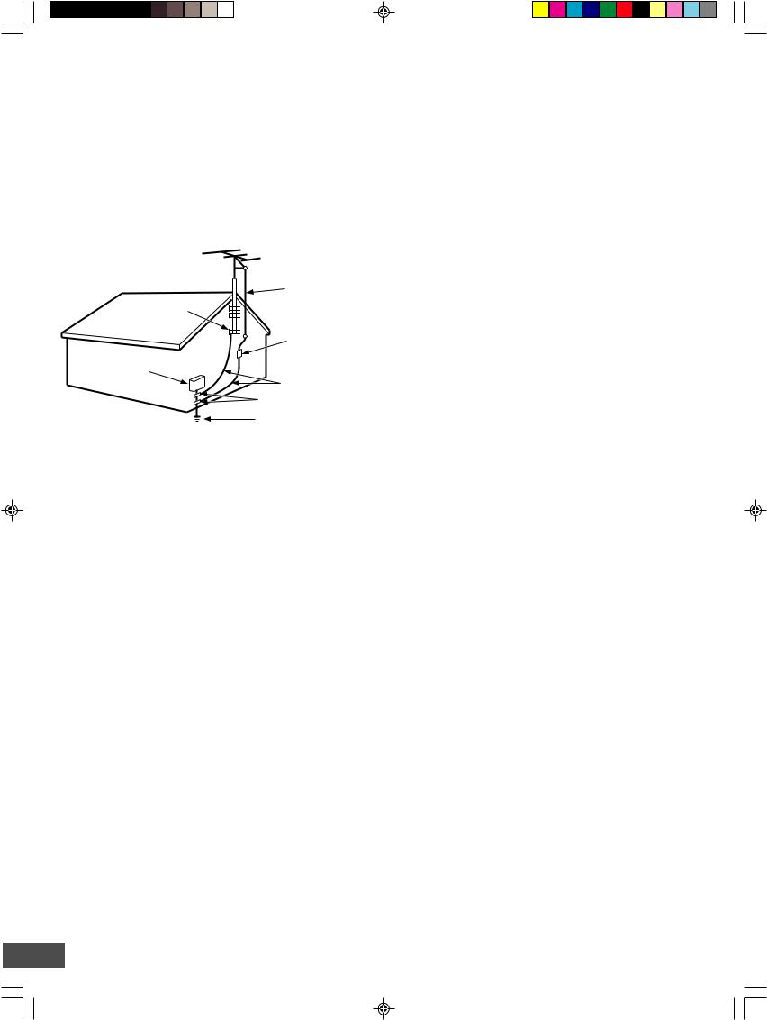
15. Outdoor Antenna Grounding – If an outside antenna or |
18. Object and Liquid Entry – Never push objects of any kind |
||||||
cable system is connected to the product, be sure the antenna or |
into this product through openings as they may touch dangerous |
||||||
cable system is grounded so as to provide some protection |
voltage points or short-out parts that could result in a fire or |
||||||
against voltage surges and built-up static charges. Article 810 of |
electric shock. Never spill liquid of any kind on the product. |
||||||
the National Electrical Code, ANSI/NFPA 70, provides information |
|
|
|
||||
with regard to proper grounding of the mast and supporting |
19. Servicing – Do not attempt to service this product yourself |
||||||
structure, grounding of the lead-in wire to an antenna discharge |
as opening or removing covers may expose you to dangerous |
||||||
unit, size of grounding conductors, location of antenna-discharge |
voltage or other hazards. Refer all servicing to qualified service |
||||||
unit, connection to grounding electrodes, and requirements for |
personnel. |
||||||
the grounding electrode. See Figure 2. |
|
|
|
|
|||
|
|
|
|
|
20. Damage Requiring Service – Unplug this product from the |
||
EXAMPLE OF ANTENNA GROUNDING AS PER |
wall outlet and refer servicing to qualified service personnel |
||||||
NATIONAL ELECTRICAL CODE, ANSI/NFPA 70 |
under the following conditions: |
||||||
|
|
|
|
|
|
a. When the power-supply cord or plug is damaged. |
|
|
|
|
|
|
|
b. If liquid has been spilled, or objects have fallen into the |
|
|
|
|
|
ANTENNA |
|
product. |
|
|
|
|
|
|
c. If the product has been exposed to rain or water. |
||
GROUND |
LEAD IN |
|
|||||
|
d. |
If the product does not operate normally by following the |
|||||
WIRE |
|
||||||
CLAMP |
|
||||||
|
|
operating instructions. Adjust only those controls that are |
|||||
|
|
|
|
|
|
||
|
|
|
|
ANTENNA |
|
covered by the operating instructions as an improper |
|
|
|
|
|
|
adjustment of other controls may result in damage and will |
||
|
|
|
|
DISCHARGE UNIT |
|
||
|
|
|
|
|
often require extensive work by a qualified technician to |
||
ELECTRIC |
|
|
|
(NEC SECTION 810 - 20) |
|
||
SERVICE |
|
|
|
GROUNDING CONDUCTORS |
restore the product to its normal operation. |
||
EQUIPMENT |
|
|
|
e. |
If the product has been dropped or damaged in any way. |
||
|
|
|
(NEC SECTION 810 - 21) |
|
|||
|
|
|
|
|
f. |
When the product exhibits a distinct change in |
|
|
|
|
|
GROUND CLAMPS |
|
||
|
|
|
|
|
performance – this indicates a need for service. |
||
|
|
|
|
|
|
||
|
|
|
|
|
|
||
POWER SERVICE GROUNDING ELECTRODE SYSTEM
(NEC ART 250, PART H)
NEC – NATIONAL ELECTRICAL CODE
S2898A
(Figure 2)
16.Power Lines – An outside antenna system should not be located in the vicinity of overhead power lines or other electric light or power circuits, or where it can fall into such power lines or circuits. When installing an outside antenna system, extreme care should be taken to keep from touching such power lines or circuits as contact with them might be fatal.
17.Overloading – Do not overload wall outlets, extension cords, or integral convenience receptacles as this can result in a risk of fire or electric shock.
21.Replacement Parts – When replacement parts are required, be sure the service technician has used replacement parts specified by the manufacturer or have the same characteristics as the original part. Unauthorized substitutions may result in fire, electric shock, or other hazards.
22.Safety Check – Upon completion of any service or repairs to this product, ask the service technician to perform safety checks to determine that the product is in proper operating condition.
23.Heat – The product should be situated away from heat sources such as radiators, heat registers, stoves, or other products (including amplifiers) that produce heat.
-E3-
SAFETY CERTIFICATION
This unit is made and tested to meet exacting safety standards. It meets UL and FCC requirements and complies with safety performance standards of the U.S. Department of Health and Human Services.
CAUTION - USE OF CONTROLS OR ADJUSTMENTS OR PERFORMANCE OF PROCEDURES OTHER THAN THOSE SPECIFIED HEREIN MAY RESULT IN HAZARDOUS RADIATION EXPOSURE.
THIS UNIT SHOULD NOT BE ADJUSTED OR REPAIRED BY ANYONE EXCEPT PROPERLY QUALIFIED SERVICE PERSONNEL.
FCC INFORMATION
This device complies with Part 15 of the FCC Rules. Operation is subject to the following two conditions:
(1) This device may not cause harmful interference, and (2) this device must accept any interference received, including interference that may cause undesired operation.
CAUTION:
Changes or modifications not expressly approved by Sanyo may void the user's authority to operate this equipment.
Note:
This equipment has been tested and found to comply with the limits for a Class B digital device, pursuant to Part 15 of the FCC Rules. These limits are designed to provide reasonable protection against harmful interference in a residential installation. This equipment generates, uses and can radiate radio frequency energy and, if not installed and used in accordance with the instructions, may cause harmful interference to radio communications. However, there is no guarantee that interference will not occur in a particular installation. If this equipment does cause harmful interference to radio or television reception, which can be determined by turning the equipment off and on, the user is encouraged to try to correct the interference by one or more of the following measures:
•Reorient or relocate the receiving antenna.
•Increase the separation between the equipment and receiver.
•Connect the equipment into an outlet on a circuit different from that to which the receiver is connected.
•Consult the dealer or an experienced radio/TV technician for help.
THIS CLASS B DIGITAL APPARATUS COMPLIES WITH CANADIAN ICES-003.
CET APPAREIL NUMÉRIQUE DE CLASSE B EST CONFORME AUX EXIGENCES DU RÉGLEMENT CANADIEN ICES-003.
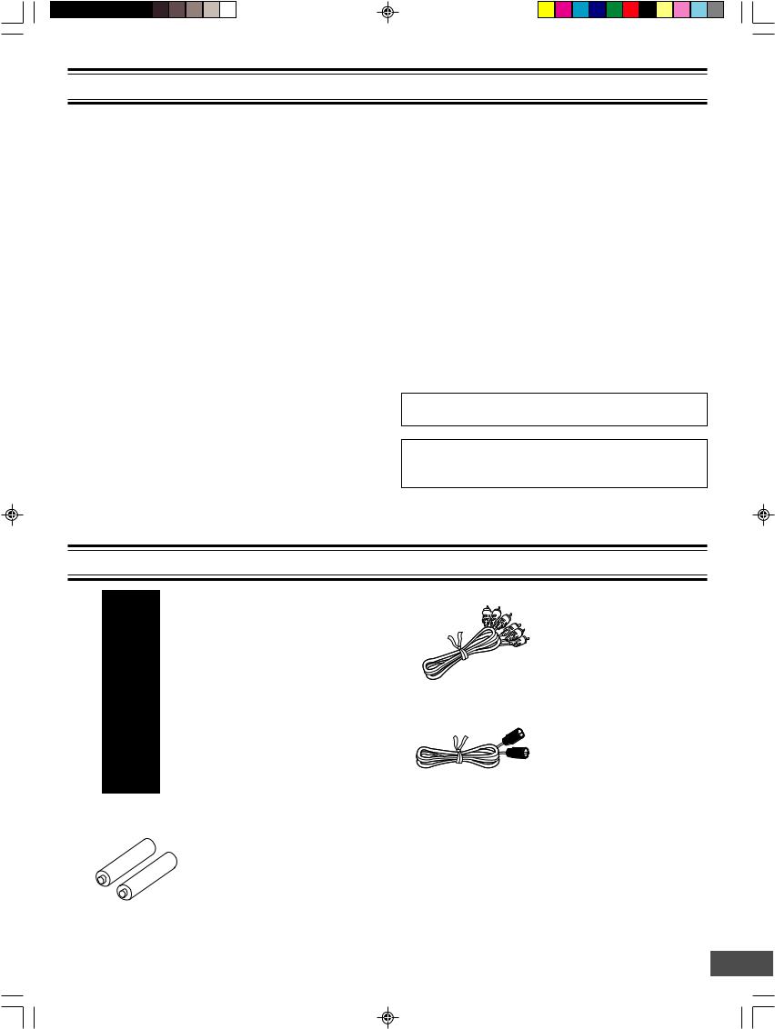
ACCESSORIES
Audio/Video cable
RB-DRW500 wireless remote control
75-ohm coaxial antenna cable
REMOTE CONTROLLER RB-DRW500
AA size battery (manganese)
Quantity: 1 pair
-E4-
CONTROLS
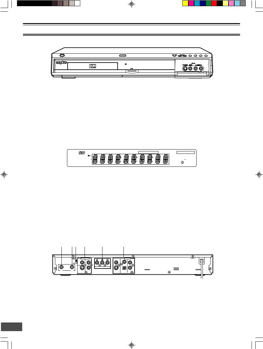
Front Panel |
1 |
2 |
3 |
4 |
5 6 |
|
7 8 9 |
|||||||||||
|
|
|
|
|
|
|
|
|
|
|
|
|
|
|
|
|
|
|
|
|
|
|
|
|
|
|
|
|
|
|
|
|
|
|
|
|
|
|
|
|
|
|
|
|
|
|
|
|
|
|
|
|
|
|
|
|
|
|
|
|
|
|
|
|
|
|
|
|
|
|
|
|
|
|
|
|
|
|
|
|
|
|
|
|
|
|
|
|
|
|
|
|
|
|
|
|
|
|
|
|
|
|
|
|
|
|
|
|
|
|
|
|
|
|
|
|
|
|
|
|
|
|
|
|
|
|
|
|
|
|
|
|
|
|
|
|
|
|
|
|
|
|
|
|
|
|
|
|
|
|
12 |
|
11 |
|
|
|
|
|
|
|
|
10 |
|
||||
1. |
|
Power button (POWER) |
|
|
|
|
|
|
|
|
|
|
|
|
|
|
|
|
|
9. |
Play button (a) |
|
|
|
|
|
|
|
|
|||||
2. |
|
Disc tray |
|
|
|
|
|
|
|
|
|
|
|
|
|
|
|
|
|
|
|
|
|
10. |
2nd AV input jacks (AV2 IN) |
|
||||||||
3. |
|
Open/Close button (q OPEN/CLOSE) |
|
|
|
|
|
|
|
|
|
|
|
S-video input jack (S-VIDEO) |
|
|||||||||||||||||||
4. |
|
FL display |
|
|
|
|
|
|
|
|
|
|
|
|
|
|
|
|
|
|
|
|
|
|
Video input jack (VIDEO) |
|
|
|
||||||
5. |
Record mode button (REC MODE) |
|
|
|
|
|
|
|
|
|
|
|
Audio input jacks (L-AUDIO-R) |
|
||||||||||||||||||||
6. |
TV channel scanning button (- CHANNEL +) |
|
|
|
|
|
|
|
|
11. |
Record button and indicator (m REC) |
|||||||||||||||||||||||
7. |
|
Skip/Next/Previous buttons (f , e) |
|
|
|
|
|
|
|
|
|
|
12. |
Remote sensor (IR) |
|
|
|
|
|
|
||||||||||||||
8. |
|
Stop button (n) |
|
|
|
|
|
|
|
|
|
|
|
|
|
|
|
|
|
|
|
|
|
|
|
|
|
|
|
|
|
|
|
|
|
|
|
|
|
|
|
|
|
|
|
|
|
|
|
|
|
|
|||||||||||||||||
FL Display |
|
|
|
|
1 2 3 4 |
5 |
6 |
7 |
8 |
|
|
|
9 |
10 |
11 |
|
|
|||||||||||||||||
|
|
|
|
|
|
|
|
|
|
|
|
|
|
|
|
|
|
|
|
|
|
|
|
|
|
|
|
LP EP + |
|
|||||
|
|
|
19 |
|
|
|
|
|
RW |
TITLE |
CH |
CHP |
SHUFF |
PROG |
REP 1 ALL A-B |
REC HQ SP |
|
|||||||||||||||||
|
|
|
|
sDIGITAL |
|
|
|
|
|
|
|
|
|
|
|
|
|
|
|
|
|
|
|
|
|
|
SAP |
|
TV |
|
12 |
|||
|
|
|
|
|
|
|
|
|
|
|
|
|
|
|
|
|
|
|
|
|
|
|
|
|
|
|
|
|||||||
|
|
|
|
|
ST |
|
CD |
|
|
|
|
|
|
|
|
|
|
|
|
|
|
|
|
|
|
|
||||||||
|
|
|
|
|
|
|
|
|
|
|
|
|
|
|
|
|
|
|
|
|
|
|
|
|
|
|
|
|||||||
|
|
|
|
|
|
|
|
|
|
|
|
|
|
|
|
|
|
|
|
|
|
|
|
|
|
|
|
|
|
|
|
|||
|
|
|
|
|
18 |
|
16 |
|
|
|
|
|
|
|
|
|
15 |
|
|
|
|
|
14 |
|
|
|
|
|||||||
|
|
|
|
|
|
|
17 |
|
|
|
|
|
|
|
|
|
|
|
|
|
|
|
|
|
|
|
13 |
|
|
|||||
1. |
DVD indicator (DVD) |
|
|
|
|
|
|
|
|
|
|
|
|
|
|
|
|
|
|
|
11. |
Record mode indicators (HQ, SP, LP, EP, +) |
||||||||||||
2. |
DVD rewritable indicator (RW) |
|
|
|
|
|
|
|
|
|
|
12. |
TV indicator (TV) |
|
|
|
|
|
|
|||||||||||||||
3. |
Play indicator (a) |
|
|
|
|
|
|
|
|
|
|
|
|
|
|
|
|
|
|
|
13. |
Second Audio Program indicator (SAP) |
||||||||||||
4. |
Title indicator (TITLE) |
|
|
|
|
|
|
|
|
|
|
|
|
|
|
|
|
|
|
|
14. |
Timer indicator (0) |
|
|
|
|
|
|
||||||
5. |
Channel indicator (CH) |
|
|
|
|
|
|
|
|
|
|
|
|
|
|
|
|
|
15. |
Message or number indicators |
|
|||||||||||||
6. |
Chapter indicator (CHP) |
|
|
|
|
|
|
|
|
|
|
|
|
|
|
|
|
|
|
(Title, chapter, track, playing time or other information) |
||||||||||||||
7. |
Shuffle indicator (SHUFF) |
|
|
|
|
|
|
|
|
|
|
|
|
|
|
|
|
|
16. |
Pause indicator (k) |
|
|
|
|
|
|
||||||||
8. |
Program indicator (PROG) |
|
|
|
|
|
|
|
|
|
|
|
|
|
|
|
|
|
17. |
CD indicator (CD) |
|
|
|
|
|
|
||||||||
9. |
Repeat indicators (REP1, ALL, A-B) |
|
|
|
|
|
|
|
|
|
|
18. |
Stereo indictor (ST) |
|
|
|
|
|
|
|||||||||||||||
10. |
Record indicator (REC) |
|
|
|
|
|
|
|
|
|
|
|
|
|
|
|
|
|
19. |
Dolby Digital indicator (s DIGITAL) |
||||||||||||||
|
|
|
|
|
|
|
|
|
|
|
|
|
|
|
|
|
|
|
|
|
|
|
|
|
|
|
|
|
||||||
Back Panel |
1 |
2 3 |
|
4 |
|
|
|
|
5 |
|
|
|
|
6 |
|
|
|
|
|
|
|
|
|
|
|
|
|
|
||||||
|
RF OUTPUT CHANNEL |
|
ANTENNA |
IN |
OUT |
3
4
AV 1 IN |
|
VIDEO |
|
OUT |
VIDEO |
|
|
|
|
|
|
|
|
|
L |
|
|
|
L |
R |
|
COMPONENT VIDEO OUT |
|
R |
S-VIDEO |
AUDIO |
S-VIDEO |
DIGITAL |
AUDIO |
|
|
AUDIO |
||
|
|
|
|
1.VHF/UHF antenna input jack (ANTENNA IN)
2.VHF/UHF antenna output jack (ANTENNA OUT)
3.RF output channel switch (RF OUTPUT CHANNEL)
4.1st AV input jacks (AV1 IN) Video input jack (VIDEO) S-video input jack (S-VIDEO) Audio input jacks (L/R AUDIO)
5.Component video output jacks (COMPONENT VIDEO OUT)
6.AV output jacks (OUT) Video output jack (VIDEO)
S-video output jack (S-VIDEO)
Coaxial digital audio output and Optical digital audio output jacks (DIGITAL AUDIO)
Audio output jacks (L/R AUDIO)
-E5-
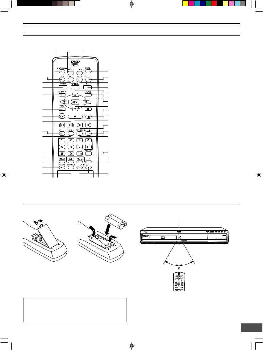
REMOTE CONTROL
1 2 3
|
4 |
|
35 |
5 |
|
34 |
6 |
|
33 |
7 |
|
32 |
8 |
|
9 |
||
|
||
|
10 |
|
31 |
11 |
|
12 |
||
|
||
30 |
13 |
|
29 |
14 |
|
|
15 |
|
28 |
16 |
|
27 |
17 |
26 |
|
|
18 |
25 |
19 |
24 |
20 |
23 |
|
22 |
21 |
1.Open/Close button (OPEN/CLOSE)
2.Angle button (ANGLE)
3.TV/DVD select button (TV/DVD)
4.Power button (POWER)
5.Shuffle button (SHUFFLE)
6.Input select button (INPUT)
7.Menu button (MENU)
8.Top menu button (TOP MENU)
9.Audio button (AUDIO)
10.Directional arrow buttons (o, a, p, b)
11.Enter button (ENTER)
12.Pause button (k)
13.Stop button (n)
14.Play button (a)
15.Fast forward/Fast reverse buttons (d, c)
16.Search mode button (SEARCH MODE)
17.Return button (RETURN)
18.Display button (DISPLAY)
19.Muting button (MUTE)
20.TV button (TV)
21.TV channel scanning buttons (- CHANNEL +)
22.Record mode button (REC MODE)
23.Record button (m RECORD)
24.Clear button (CLEAR)
25.Edit button (EDIT)
26.Number buttons (1 – 9, 0, +10)
27.Clock button (CLOCK)
28.Zoom button (ZOOM)
29.Skip/Next/Previous buttons (f, e)
30.Slow motion playback button (Ia)
31.Program button (PROG)
32.Subtitle button (SUBTITLE)
33.Setup button (SETUP)
34.A-B repeat button (A-B)
35.Repeat button (REPEAT)
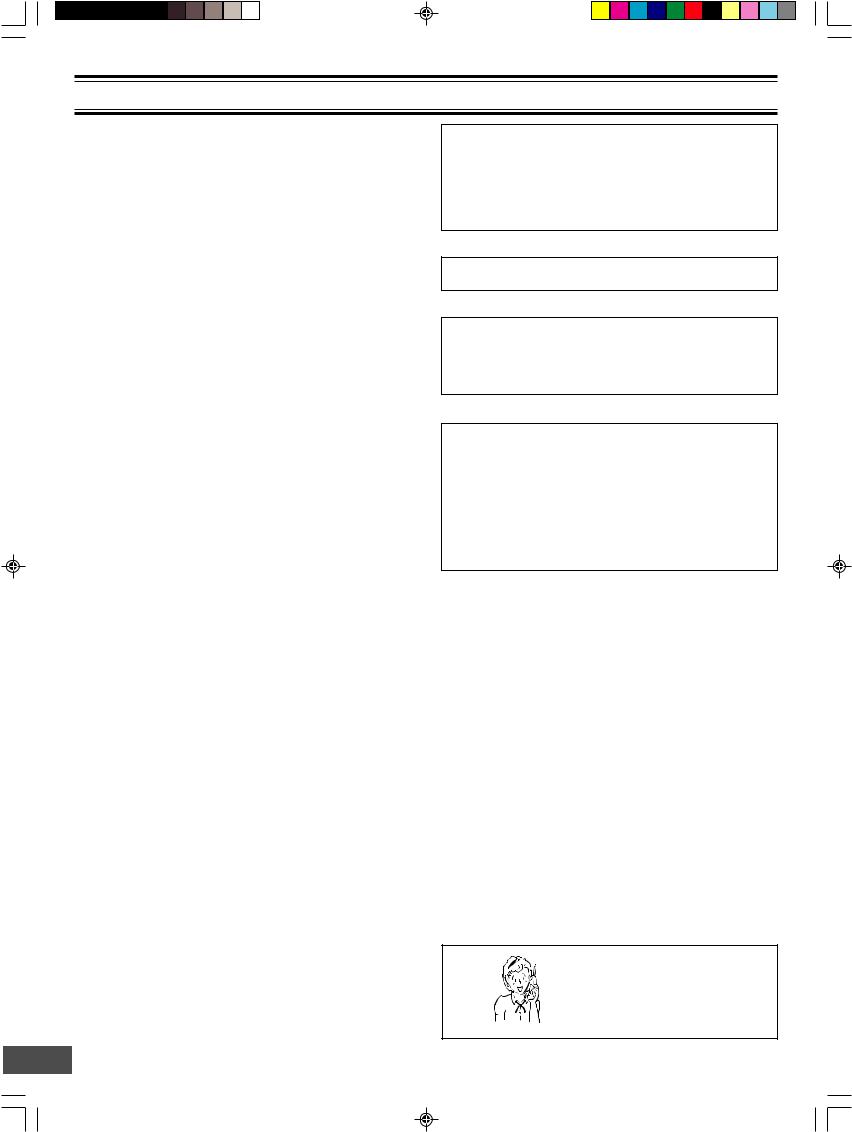
Inserting batteries |
|
Two "AA" batteries |
1 |
2 |
(supplied) |
|
Note:
Remove the batteries if the remote control is not to be used for a month or more. Batteries left in the unit may leak and cause damage.
IMPORTANT NOTE:
SPENT OR DISCHARGED BATTERIES MUST BE RECYCLED OR DISPOSED OF PROPERLY IN COMPLIANCE WITH ALL APPLICABLE LAWS.
FOR DETAILED INFORMATION, CONTACT YOUR LOCAL COUNTY SOLID WASTE AUTHORITY.
Remote control range
Remote sensor
30° |
30° |
Within approx. 20 feet |
(6 meters) |
Note:
This is not Multi-brand Remote Control.
It cannot operate your TV and VCR.
-E6-
FOR SAFE AND EFFICIENT OPERATION
•Do not damage the power cord.
•When not in use, disconnect the power cord from the outlet. Grasp the plug, not the cord, when disconnecting the unit.
•If water should enter the unit, electrical shock or a malfunction may result. Use in an area where there is low humidity and little dust.
•Do not disassemble or alter the unit in any way.
•Do not use the unit in areas where extremes in temperature occur (below 40°F (5°C) or exceeding 95°F (35°C)), or where it may be exposed to direct sunlight.
•Because of the DVD recorder extremely low noise and wide dynamic range, there is a tendency to set the volume on the amplifier higher than necessary. Doing so may produce an excessively high output from the amplifier which can cause damage to your speakers. Please be careful in this regard.
•Sudden changes in the surrounding temperature can cause dew to form on the optical pickup lens inside the unit. Under this condition the unit may be unable to operate properly. If this should occur, remove the disc and allow the unit to adjust to the surrounding temperature.
•When carrying the unit, be sure to remove a disc which may be inside and turn the power off. Then unplug the power cord from the AC outlet after 10 seconds. Carrying the unit with a disc inside may damage the disc and/or the unit.
•Do not install this equipment in a confined space, such as a book case or built in cabinet.
CAUTION:
The unit must be operated in a horizontal position only. The unit must be placed in a well ventilated area.
Do not place any object on the top of the unit. Do not block ventilation holes.
The cabinet of the unit warms up when it is used for a long time, however it is not a malfunction.
Press [q OPEN/CLOSE] (or [OPEN/CLOSE] on the remote control) when closing the disc tray. Do not push the disc tray.
To reduce the volume temporarily (muting)
Press [MUTE] on the remote control. “MUTE” appears on the TV screen.
To restore the previous volume setting, press [MUTE] again. “MUTE OFF” appears briefly on the TV screen.
WHAT TO DO IF...
If the operation of the unit or display is not normal, even though the appropriate buttons have been pressed.
1.Disconnect the power cord.
2.Connect the power cord again.
3.Operate the unit again.
Note:
If the unit still does not operate correctly, please contact your nearest Sanyo Authorized Service Facility.
Need help? Call
1-800-813-3435
-E7-
BASIC CONNECTION
Notes:
•Unpack the unit and insert the two AA size batteries in the remote control (See page E6).
•Do not connect the power cord to a 120VAC 60Hz outlet until all connections have been made.
Before Connection
This guide will help you to connect the unit.
Step 1: Connecting the Antenna Cable (See page E8.)
Step 2: Connecting the Video Cables (See page E11.)
Step 3: Connecting the Audio Cables (See page E12.)
Step 4: Connecting the Power Cord (See page E14.)
Need help? Call
1-800-813-3435
Step 1: Connecting the Antenna Cable
First, select one of the following antenna connections that best suit you.
If you use |
See |
|
|
Antenna only (no cable TV), or cable without cable box |
Example: Basic Antenna/Cable connections (Page E9) |
|
|
Cable box with a few or many scrambled channels |
Example: Connecting a Cable Box (Page E10) |
|
|
Note to CATV system installer:
This reminder is provided to call the CATV system installer’s attention to Section 820-40 of the NEC which provides guidelines for proper grounding and, in particular, specifies that the cable ground shall be connected to the grounding system of the building, as close to the point of cable entry as practical.
Notes:
•If the antenna is a flat cable (300-ohm twin lead cable), use a 300-75 ohm matching transformer (not supplied) to connect the antenna to the unit.
•If you use separate VHF and UHF antenna cables, use a VHF/UHF band combiner (not supplied) to connect the antenna to the unit.
•If you are not sure about the connection, please consult your audio/video dealer.
CAUTION:
Do not connect the antenna and VCR as shown below. Your VCR doesn’t work.
VCR |
DVD recorder |
TV |
DVD recorder |
VCR |
TV |
-E8-
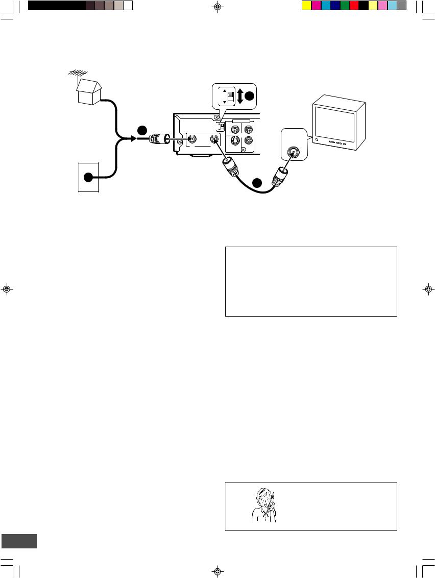
Example: Basic Antenna/Cable Connections
DVD recorder |
RFOUTPUT CHANNEL |
|
|
(Partial back panel) |
|
|
OUTPUTRF CHANNEL |
1 |
3 |
4 |
|
ANTENNA |
|
or |
|
IN |
OUT |
75-ohm coaxial antenna cable (not supplied)
3 |
2 |
4 |
AV 1 IN
VIDEO
L

 VHF/UHF R ANTENNA
IN
S-VIDEO AUDIO
TV
3
Cable TV wall jack
75-ohm coaxial antenna cable (supplied)
1.Connect an antenna (or a cable TV system) to the unit.
2.Set the RF OUTPUT CHANNEL switch to “3” or “4”.
3.Connect the unit to the TV with the 75-ohm coaxial antenna cable (supplied).
Channel Switch Setting
Set your TV to either channel 3 or channel 4. (Choose a channel that is not used for broadcasting in your area.)
Then set the RF OUTPUT CHANNEL switch to channel 3 or 4 to match the channel selected on the TV. This is your unit channel.
The TV must be set to this channel whenever the unit is used for playing a disc or watching a TV program.
If in doubt, check with your local cable company.
Need help? Call
1-800-813-3435
-E9-
Example: Connecting a Cable Box
This unit can receive all unscrambled cable channels without the use of a cable box. If you wish to view and record scrambled cable channels, you must connect a cable box as described below.
Your local cable TV company will advise you of the channels available in your area.
We recommend that you consult your cable TV company to make sure that the cable is properly connected.
Example:
Connecting a cable box with many scrambled channels
Use this connection if your cable system scrambles all or most channels.
Connect the cable box to the unit first.
Notes:
•The unit and TV receive the same channel. Be sure that the cable box is turned on.
•Recording one channel while watching another channel is not possible.
Cable box (not supplied)
CATV
75-ohm coaxial antenna cable (not supplied)
DVD recorder
(Partial back panel) |
RFOUTPUT CHANNEL |
|
|
AV 1 IN |
3 |
VIDEO |
|
||
|
4 |
|
L |
|
|
ANTENNA |
|
|
|
|
|
|
|
R |
IN |
OUT |
|
S-VIDEO |
AUDIO |
VHF/UHF
ANTENNA
IN
TV
75-ohm coaxial antenna cable (supplied)
Example:
Connecting a cable box with only a few scrambled channels
Use this connection if your cable system scrambles only a few channels.
Connect the cable box between the unit and the TV.
Notes:
•You can record any non-scrambled channel by selecting the channel on the unit.
•You cannot record scrambled channels that require a cable box.
|
|
DVD recorder |
|
|
|
|
|
|
|
(Partial back panel) |
|
||||
|
|
|
OUTPUTRF |
CHANNEL |
|
|
AV 1 IN |
|
|
|
3 |
VIDEO |
L |
||
|
|
|
|
|
|
|
|
|
|
|
|
|
4 |
|
|
|
|
ANTENNA |
|
|
|
|
|
CATV |
|
|
|
|
|
|
R |
|
IN |
OUT |
|
|
S-VIDEO |
AUDIO |
|
75-ohm |
coaxial |
|
|
|
|
|
|
antenna cable |
|
|
|
|
|
|
|
(not supplied) |
|
|
|
|
|
|
|
|
|
75-ohm coaxial antenna |
|
||||
Cable box (not supplied) |
cable (supplied) |
|
|
|
|
||
|
|
|
|
|
|
||
TO TV |
ANT. IN |
VHF/UHF
ANTENNA
IN
TV
75-ohm coaxial antenna cable (not supplied)
Need help? Call
1-800-813-3435
-E10-

Step 2: Connecting the Video Cable
Connect the unit to your TV.
Select one of the following examples.
(If the TV has an antenna input jack only, skip this step.)
Note:
For AUDIO connection, see page E12.
Example:
Connecting to the VIDEO OUT jack
Need help? Call
1-800-813-3435
Connect the yellow plug of the Audio/Video cable to the video (yellow) jack.
You can enjoy standard picture images.
Note:
Connect the right (red) and left (white) plugs of the Audio/Video cable to the audio input jacks (see page E12).
OUTPUTRF CHANNEL |
3 |
|
4 |
ANTENNA
IN |
OUT |
|
AV 1 IN |
|
VIDEO |
|
OUT |
VIDEO |
|
|
|
|
|
|
|
|
|
|
|
|
L |
|
|
|
L |
|
R |
|
COMPONENT VIDEO OUT |
|
R |
S-VIDEO |
|
AUDIO |
S-VIDEO |
DIGITAL |
AUDIO |
|
|
|
AUDIO |
||
|
|
|
|
|
AUDIO R-AUDIO-L VIDEO VIDEO
INPUT 1
DVD recorder (Partial back panel)
To VIDEO OUT jack (Yellow)
Audio/Video cable (supplied)
Example:
Connecting to the S-VIDEO OUT jack
Connect the S-video cable (not supplied) as shown below. (The VIDEO OUT jack connection is not necessary.)
You can enjoy clearer picture images.
For AUDIO connection, see page E12.
TV
 (Yellow)
Example:
Connecting to the COMPONENT VIDEO OUT jacks
Connect a component video cable (not supplied) as shown below. (The VIDEO OUT or S-VIDEO OUT jack connection is not necessary.) You can enjoy high quality picture images.
For AUDIO connection, see page E12.
If you use a TV with Progressive-scan Capability, set the unit to the PROGRESSIVE mode. See page E44.
DVD recorder (Partial back panel)
VIDEO |
|
OUT |
|
|
|
|
|
|
|
|
L |
NENT VIDEO OUT |
|
|
R |
|
|
|
S-VIDEO IN 1 |
S-VIDEO |
DIGITAL |
AUDIO |
TV |
AUDIO |
|||
To S-VIDEO |
To S-video input jack |
||
OUT jack |
|
||
*S-video cable (not supplied)
TV
DVD recorder (Partial back panel)
|
OU |
|
VIDEO |
COMPONENT VIDEO OUT |
COMPONENT VIDEO INPUT |
Green |
Blue |
S-VIDEO |
DIGITAL |
Y |
PB |
PR |
AUDIO |
 Red
Red
To COMPONENT
VIDEO OUT jacks
 To component video *Component video cable (not supplied) input jacks
* Please consult your local audio/video dealer.
-E11-
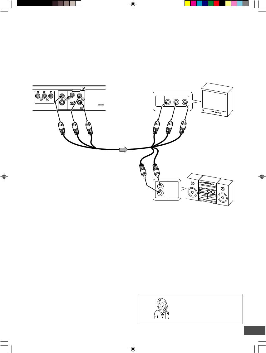
Step 3: Connecting the Audio Cables
Select the audio connection that best suits your system. (If the TV has an antenna input jack only, skip this step.)
Note:
For VIDEO connection, see page E11.
Example:
Connecting to your TV (or Audio System)
The built-in speakers in your TV will sound.
DVD recorder (Partial back panel)
VIDEO |
|
OUT |
|
|
|
||
|
|
L |
|
COMPONENT VIDEO OUT |
|
R |
|
S-VIDEO |
DIGITAL |
AUDIO |
|
AUDIO |
|||
|
|
|
L |
R |
*(Yellow) |
(White) |
(Red) |
|
|
|
|
|
To AUDIO OUT jacks |
TV with Audio/Video input jacks
To audio input jacks
AUDIO R-AUDIO-L VIDEO VIDEO
INPUT 1
R |
L |
|
(Red) |
(White) |
*To video input (Yellow) |
|
|
or
Audio/Video cable (supplied)
*The yellow plug is used for video connection. See page E11.
Notes:
•If your TV has one audio input jack, connect the AUDIO OUT jacks of the unit to a Y-cable adaptor (not supplied), then connect it to the TV’s audio input jack. Please consult your local audio/video dealer.
•Do not connect the AV1 IN or AV2 IN (AUDIO L/R) jacks of the unit to your TV’s audio output jacks at the same time.
(Red)R |
(White)L |
L
AUDIO
INPUT
R
To audio input jacks
Audio System
Need help? Call
1-800-813-3435
-E12-
Example:
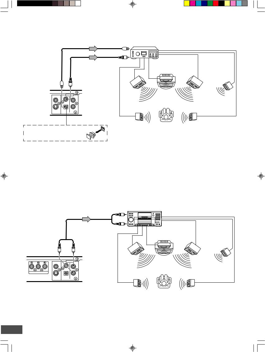
Connecting to an Amplifier with Dolby Digital Decoder or DTS Decoder
Connect the audio cable and/or coaxial digital cable or optical digital cable.
To digital audio input |
Amplifier with Dolby Digital Decoder |
|
or DTS Decoder |
|
|
|
or |
|
|
*Optical digital cable |
|
*Coaxial digital cable |
|
|
|
(not supplied) |
|
|
Center |
|
|
|
(not supplied) |
|
|
||
|
|
|
speaker |
|
|
|
|
|
|
|
|
|
or |
|
|
|
|
To Optical DIGITAL |
|
To Coaxial DIGITAL |
|
|
|
AUDIO OUT jack |
|
AUDIO OUT jack |
|
|
|
|
|
|
Front left |
Front right |
|
VIDEO |
|
OUT |
speaker |
speaker |
Subwoofer |
|
|
||||
|
|
L |
|
|
|
|
|
|
|
|
|
|
|
R |
Surround left |
Surround right |
|
|
AUDIO |
|
speaker |
speaker |
|
S-VIDEO |
DIGITAL |
AUDIO |
|
|
|
|
|
|
|
||
DVD recorder |
|
|
|
|
|
(Partial back panel) |
|
|
|
|
|
Before connecting, remove the protective cap from the jack. Replace the cover when the jack is not in use.
*Please consult your local audio/video dealer.
To enjoy Dolby Digital or DTS sound
Set “Digital Out” to “ON” in “Audio Setup” screen. See page E31.
Example:
Connecting to an Amplifier with Dolby Pro Logic Decoder
Manufactured under license from Dolby Laboratories.
“Dolby”, “Pro Logic” and the double-D symbol are trademarks of Dolby Laboratories.
“DTS” and “DTS Digital Out” are trademarks of Digital Theater Systems, Inc.
|
|
To AUDIO INPUT jacks |
Amplifier with Dolby Pro Logic Decoder |
|
|
|
|
|
|
|
|
*Audio cable |
|
|
|
|
|
(not supplied) |
|
|
|
|
|
|
|
|
|
Center |
|
|
|
|
|
speaker |
|
DVD recorder |
|
To AUDIO OUT jacks |
|
|
|
(Partial back panel) |
|
|
|
|
|
|
|
|
|
|
|
|
|
|
Front left |
Front right |
|
VIDEO |
|
OUT |
speaker |
speaker |
Subwoofer |
|
|
||||
|
|
L |
|
|
|
|
|
|
|
|
|
COMPONENT VIDEO OUT |
|
R |
Surround left |
Surround right |
|
|
|
||||
|
DIGITAL |
|
|||
S-VIDEO |
AUDIO |
speaker |
speaker |
|
|
AUDIO |
|
||||
Note: |
|
|
|
|
|
Please refer to your amplifier instruction manual. |
|
|
|
||
|
|
|
*Please consult your local audio/video dealer. |
|
|
-E13-
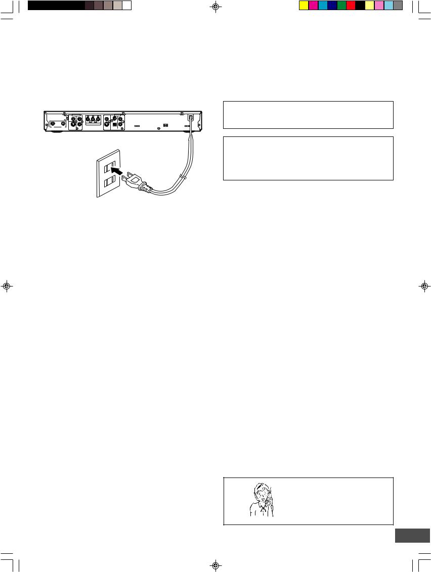
Step 4: Connecting the Power Cord
Connect the power cord to a 120VAC 60Hz outlet. This unit is equipped with a polarized plug. If you have difficulty inserting the plug, turn it over and reinsert it. If the unit will not be used for a long time, disconnect the AC plug from the AC outlet.
Notes:
•Before plugging the power cord into an AC outlet, make sure that all the connections have been made.
•The unit is not disconnected from the AC power unless the power cord is unplugged from the AC outlet.
|
RF OUTPUT CHANNEL |
|
ANTENNA |
IN |
OUT |
AV 1 IN
3  VIDEO
VIDEO
4
L
R |
COMPONENT VIDEO OUT |
S-VIDEO AUDIO
OUT
VIDEO
L
R
DIGITAL
S-VIDEO AUDIO AUDIO
CAUTION:
TO PREVENT ELECTRIC SHOCK, MATCH WIDE BLADE OF PLUG TO WIDE SLOT, FULLY INSERT.
ATTENTION :
POUR ÉVITER LES CHOC ÉLECTRIQUES‚
INTRODUIRE LA LAME LA PLUS LARGE DE LA FICHE
DANS LA BORNE CORRESPONDANTE DE LA PRISE
ET POUSSER JUSQU’ AU FOND.
To AC 120V, 60Hz
Need help? Call
1-800-813-3435
-E14-
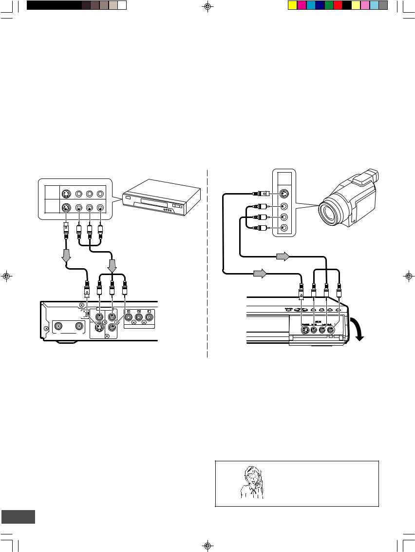
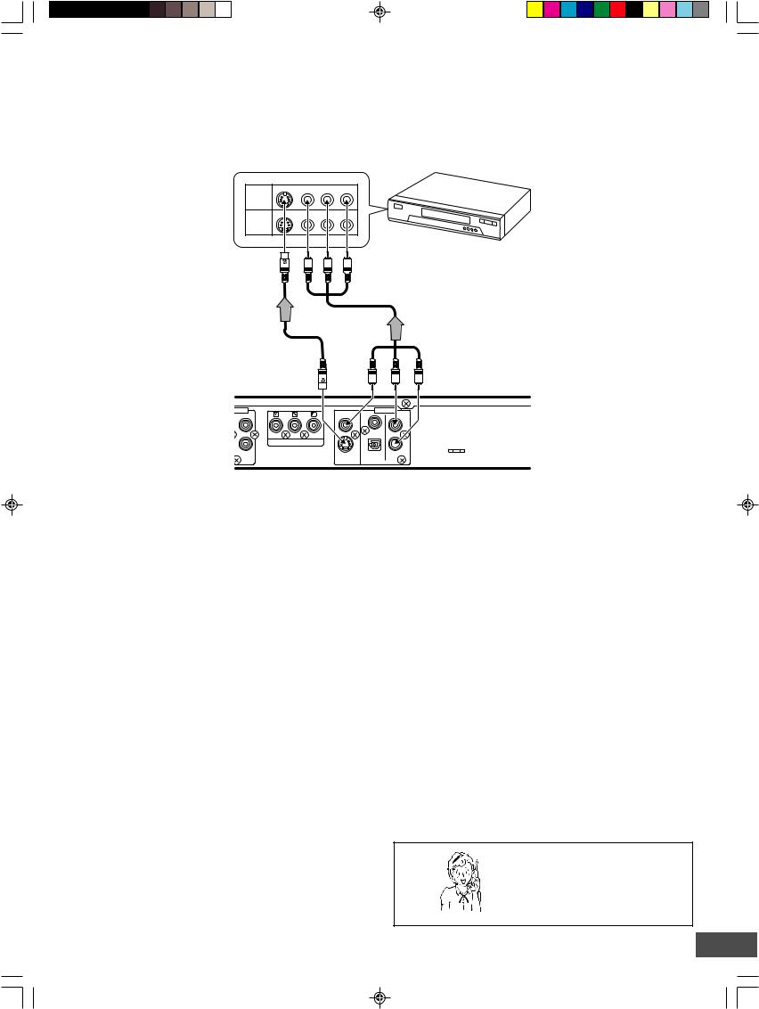
Connecting a VCR or Similar Recording Equipment to This Unit
You can use this unit as the source player or as the recording deck. First, disconnect the AC power cord from an AC outlet.
Connect a VCR or similar recording equipment to this unit as shown below. See also the owner’s manual supplied with the connected equipment.
CAUTION:
Pictures containing copyright protection signals cannot be recorded.
Example:
Connection for recording from other equipment
Connect a VCR or similar recording equipment to the AV1 IN or AV2 IN jacks.
See “AV Select” on page E32.
Note:
Do not connect the video (yellow) jack when using an S-video cable (not supplied).
A/V S-VIDEO VIDEO R-AUDIO-L
INPUT
JACKS
A/V S-VIDEO VIDEO R-AUDIO-L
OUTPUT
JACKS
VCR, etc.
 To AV output jacks
To AV output jacks
A/V
OUTPUT
JACKS
S-VIDEO
VIDEO
R
AUDIO
L
DV camcorder, etc.
|
|
|
|
*Audio/Video cable (not supplied) |
|
*S-video cable |
|
|
|
(White)L |
To AV1 IN jacks |
|
|
(Yellow) |
(Red)R |
||
(not supplied) |
|
|
|||
|
|
|
|
|
|
|
OUTPUTRF CHANNEL |
|
|
AV 1 IN |
|
|
3 |
VIDEO |
L |
|
|
|
|
|
|
|
|
|
|
4 |
|
|
|
ANTENNA |
|
|
|
|
|
|
|
|
|
R |
COMPONENT VIDEO OUT |
*Audio/Video cable (not supplied) |
|
||
|
(Yellow) |
To AV2 IN jacks |
|
*S-video cable (not supplied) |
(White)L |
(Red)R |
|
|
|
|
|
IN |
OUT |
S-VIDEO |
AUDIO |
DVD recorder (Partial back panel)
CAUTION:
Almost all videos and DVD softwares on sale have a copyprotection. You cannot record them using this unit.
Video Games cannot be recorded.
DVD recorder |
Open the lid. |
|
*Please consult your local audio/video dealer.
Need help? Call
1-800-813-3435
-E15-
Example:
Connection for recording to other equipment
Connect a VCR or similar recording equipment to the OUT jacks.
Notes:
•Do not connect the video (yellow) jack when using an S-video cable (not supplied).
•If you pass the DVD recorder signals via the VCR, you may not receive a clear image on the TV screen.
A/V S-VIDEO VIDEO R-AUDIO-L
INPUT
JACKS
A/V S-VIDEO VIDEO R-AUDIO-L
OUTPUT
JACKS
VCR, etc.
*S-video cable (not supplied)
IN
L
R |
COMPONENT VIDEO OUT |
|
AUDIO |
 To AV input jacks
*Audio/Video cable (not supplied)
ToVIDEOOUT jack(Yellow) |
(White)L |
(Red)R |
|
|
To AUDIO OUT jacks |
OUT
VIDEO
L
 R
R
DIGITAL
S-VIDEO AUDIO
AUDIO
DVD recorder (Partial back panel)
CAUTION:
Almost all videos and DVD softwares on sale have a copyprotection. You cannot record them using this unit.
*Please consult your local audio/video dealer.
Need help? Call
1-800-813-3435
-E16-
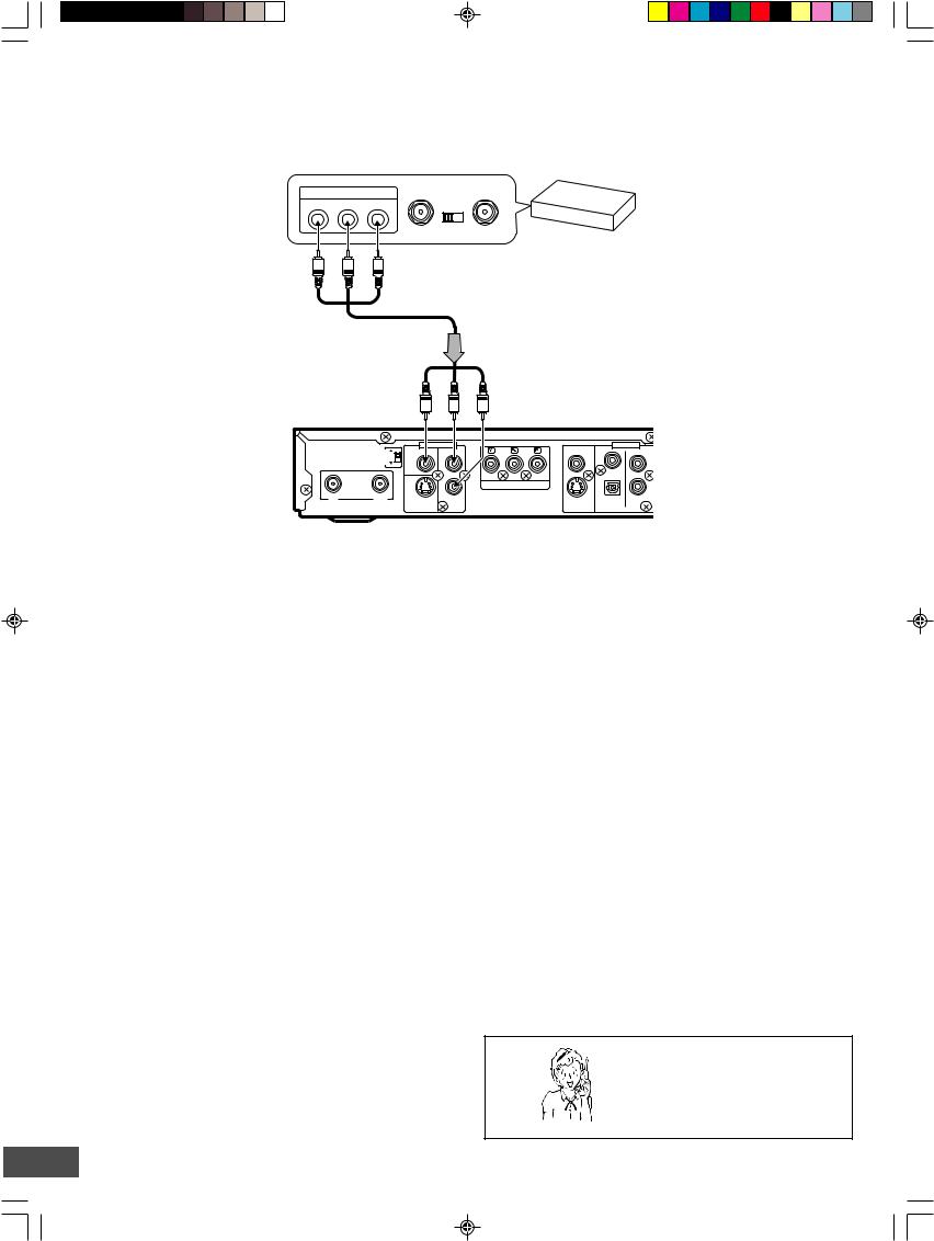
Connecting to a Satellite Receiver or a Cable Box
Connect a satellite receiver, digital cable box, or cable box to this unit using the AV1 IN jacks. First, disconnect the AC power cord from an AC outlet.
See also the owner’s manual supplied with the connected equipment.
A/V OUTPUT JACKS |
TO TV |
ANT. IN |
|
VIDEO |
R-AUDIO-L |
CHANNEL |
|
|
|
||
|
|
3 |
4 |
Satellite receiver or Cable box, etc.
 To AV output jacks
*Audio/Video cable (not supplied)
OUTPUTRF CHANNEL |
3 |
|
4 |
ANTENNA
IN |
OUT |
|
|
To AV1 IN jacks |
|
|
|
(Yellow) |
|
(White)L |
(Red)R |
|
|
|
AV 1 IN |
|
VIDEO |
|
OUT |
VIDEO |
|
|
|
|
|
|
|
|
|
|
|
|
L |
|
|
|
L |
|
R |
|
COMPONENT VIDEO OUT |
|
R |
|
|
|
|
||
S-VIDEO |
AUDIO |
|
S-VIDEO |
DIGITAL |
AUDIO |
|
|
|
AUDIO |
||
|
|
|
|
|
|
DVD recorder (Partial back panel)
CAUTION:
Pictures containing copyright protection signals cannot be recorded.
*Please consult your local audio/video dealer.
Need help? Call
1-800-813-3435
-E17-
SETTING THE CLOCK
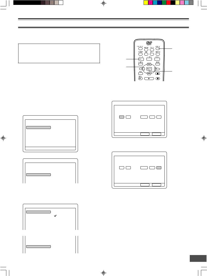
When the unit is first connected to the AC outlet (“-- : --” may brink on the FL display), or after the power has failed, please follow the steps below.
Important Note:
This unit uses the International Time System (24-hour display). Therefore the unit does not have Daylight Saving Time (DST) function. You must set the clock when summer switches to winter and vice versa.
Preparations
Turn on the TV and select the appropriate video input to suit the connections to this unit. (Refer to your TV’s owner manual.)
To Set the Clock
1.Press [POWER] to turn on the power.
•“POWER ON” appears briefly on the FL display.
•“SANYO” logo appears on the TV screen.
2.Press [SETUP] in “NO DISC” mode. “Menu” screen appears on the TV screen.
Menu
Play/Edit Disc
|
4 |
Record Program |
a Record Status |
|
5 |
Setup Menu |
Record List |
Press SETUP to exit
3. Press [p] to select “Setup Menu”.
|
Menu |
Play/Edit Disc |
Recording Setup |
Record Program |
DVD Control |
|
4 |
Setup Menu |
a General |
|
Video |
Audio
4.Press [ENTER] (or [a]). “Recording Setup” is highlighted.
5.Press [ENTER] (or [a]) again. “Recording Setup” screen appears.
Recording Setup
Record Mode |
a |
HQ |
|
5 |
|
Auto Chapter |
|
SP |
Set Clock |
|
LP |
Channel Setup |
|
EP |
|
|
EP+ |
6. Press [p] to select “Set Clock”.
Record Mode
Auto Chapter
4
Set Clock
5
Channel Setup
POWER
SETUP
4, 5, a, b
ENTER
7.Press [ENTER] (or [a]).
“Set Clock Setup” screen appears. Example:
Set Clock Setup
Select a field then use 45 to edit. |
|
|
||
Hour |
Minute |
Year |
Month |
Day |
4 |
|
|
|
|
00 |
a 00 |
2004 |
/ Jan / |
01 |
5 |
|
|
|
|
Press SETUP to exit |
Done |
Cancel |
8.Press [o], [p], [a] or [b] repeatedly (or number buttons) to set the date and time.
Example:
Set Clock Setup
Select a field then use 45 to edit. |
|
||
Hour |
Minute |
Year |
Month Day |
|
|
|
4 |
08 |
: 30 |
2004 |
/ May b 01 a |
|
|
|
5 |
Press SETUP to exit |
Done |
Cancel |
9.Press [a] to select “Done”. Note:
If you want to cancel it, press [a] to select “Cancel”, and then press [ENTER]. “Recording Setup” screen returns.
10.Press [ENTER].
•“Recording Setup” screen returns.
•“Set Clock” is highlighted.
11.Press [SETUP].
“Recording Setup” screen disappears.
12.Press [POWER] to turn off the power. The clock appears on the FL display. Example: 08:30
-E18-
TUNER SETTING
This unit is equipped with a channel memory feature which allows channels to skip up or down to the next channel set into memory, skipping over unwanted channels.
Before selecting channels, they must be programmed into the memory. In addition to normal VHF and UHF channels, this unit can receive up to 125 Cable TV channels. To use this unit with an antenna, set the “Channel Setup” menu.
Important Note:
•The antenna must be connected to this unit. See pages E8 ~ E10.
•You may need extra instructions during this setting. If a message appears, please follow the instructions displayed on the TV screen.
•For improvement, on-screen display subject to change without notice.
Setting “Channel Setup”
1.Open “Recording Setup” screen.
(Repeat steps 1 ~ 5 of “To Set the Clock” on page E18.)
|
Recording Setup |
Record Mode |
a HQ |
|
5 |
Auto Chapter |
SP |
Set Clock |
LP |
Channel Setup |
EP |
|
EP+ |
|
|
Press SETUP to exit |
Current selection |
2.Press [p] to select “Channel Setup”.
3.Press [ENTER] (or [a]) to select the sub menu.
|
Recording Setup |
Record Mode |
|
Auto Chapter |
b Auto CH Scan |
|
5 |
Set Clock |
Channel List |
Channel Setup |
Modify Channel |
|
Tuner Select |
|
MTS Select |
|
|
Press SETUP to exit |
|
4.Press [p] or [o] to select the item.
Auto CH Scan ===> See page E20. Channel List ===> See page E20.
Modify Channel |
===> |
See page E21. |
Tuner Select |
===> |
See the right column. |
MTS Select |
===> |
See page E21. |
If you use this unit for first time, select “Tuner Select”.
4, 5, a, b
ENTER
Tuner Select
Select the antenna system “CATV” or “TV”.
1) Select “Tuner Select”.
|
Recording Setup |
Record Mode |
|
Auto Chapter |
Auto CH Scan |
Set Clock |
Channel List |
Channel Setup |
Modify Channel |
|
4 |
|
b Tuner Select |
|
5 |
|
MTS Select |
Press SETUP to exit |
|
2)Press [ENTER] (or [a]).
“Tuner Select Setup” screen appears.
Tuner Select Setup
Tuner Select |
a |
CATV |
|
|
TV |
Press SETUP to exit |
Current selection |
3)Press [a] to select the sub menu.
4)Press [p] or [o] to select “CATV” or “TV”.
5)Press [ENTER]. “√” appears.
6)Press [b] repeatedly to return to “Recording Setup” screen.
Need help? Call
1-800-813-3435
-E19-
 Loading...