


MULTI-DECK FRESH PRODUCE CASES
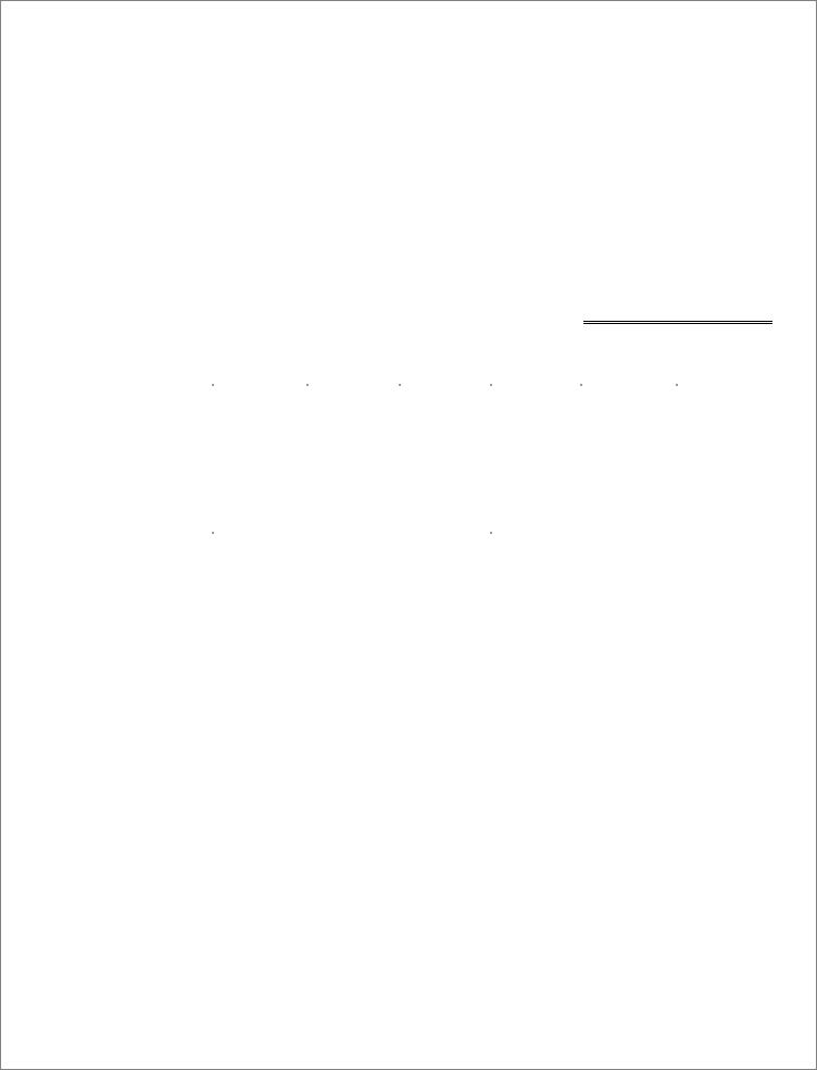
CVW-EXA184 / CVW-EXA124 |
CVW-EXA284 / CVW-EXA224 |
(H: 80 7/8”, L: 96 3/8”) / (H: 80 7/8”, L: 144 5/8”) |
(H: 84 7/8”, L: 96 3/8”) / (H: 84 7/8”, L: 144 5/8”) |
|
|
INSTALLATION & SERVICE MANUAL
REMOTE TYPE DISPLAY CASE
2010

Activity Safety Precautions
In order to prevent any injuries to person, equipment and/or damage to the SANYO Cases, sections requiring additional care to be undertaken will have one or all of the following safety reminders:
Red Safety Mark (Safety Mark A)
Extreme caution and care must be exercised when conducting this operation to ensure personal
Aand equipment safety, and to prevent product damage.
Failure to exercise extreme caution may result in severe personal injury and/or equipment and/or product damage.
Yellow Safety Mark (Safety Mark B)
Caution and care should be exercised when conducting this operation to ensure personal and
Bequipment safety, and to prevent product damage.
Failure to exercise caution may result in personal injury and/or equipment and/or product damage.
Hand Protection Required
Activities to be undertaken require finger and palm protection equipment to prevent personal injuries.
General Safety Precautions
Safety Equipment Required
Any installation where there is overhead work being conducted simultaneously where a SANYO Case is being unloaded and/or set/aligned, proper safety equipment including headgear is required to ensure personal safety.
2

TABLE OF CONTENTS
1 |
SPECIFICATIONS .................................................................................................................................................. |
5 |
||
|
1.1 |
|
CVW-EXA284 / CVW-EXA224........................................................................................................................ |
5 |
|
1.2 |
|
CVW-EXA184 / CPW-EXA124......................................................................................................................... |
6 |
2 |
DIMENSIONS........................................................................................................................................................... |
7 |
||
|
2.1 |
|
EXTERNAL DIMENSIONS ..................................................................................................................................... |
7 |
|
2.2 |
|
FOOTPRINT.......................................................................................................................................................... |
7 |
|
2.3 |
|
EXTERNAL DIMENSIONS ..................................................................................................................................... |
8 |
|
2.4 |
|
FOOTPRINT.......................................................................................................................................................... |
8 |
3 UNLOADING AND CARPENTRY PROCEDURES ........................................................................................... |
9 |
|||
|
3.1 |
|
NSF CERTIFICATION ........................................................................................................................................... |
9 |
|
3.2 |
|
LOCATION ........................................................................................................................................................... |
9 |
|
3.3 |
|
SHIPPING DAMAGE.............................................................................................................................................. |
9 |
|
3.4 |
|
UNLOADING INSTRUCTIONS & PRECAUTIONS .................................................................................................... |
9 |
|
3.5 |
|
ALIGNING CASES .............................................................................................................................................. |
10 |
|
3.6 |
|
CASE LEVELING ................................................................................................................................................ |
10 |
|
3.7 |
|
JOINING INSTRUCTIONS .................................................................................................................................... |
11 |
|
3.7.1 Applying Gasket (for connecting cases or installing side panels)............................................................ |
11 |
||
|
3.7.2 |
Connecting Cases. .................................................................................................................................... |
12 |
|
|
3.8 |
|
INSTALLING PATCH ENDS................................................................................................................................. |
13 |
|
3.9 |
|
INSTALLING KICKPLATE ................................................................................................................................... |
14 |
|
3.10 |
|
INSTALLING HANDRAIL AND BUMPER.............................................................................................................. |
15 |
4 REFRIGERATION, PLUMBING & ELECTRICAL PROCEDURES ............................................................ |
16 |
|||
|
4.1 |
|
PIPING (PLUMBING, REFRIGERATION) .............................................................................................................. |
16 |
|
4.2 |
ELECTRICAL DATA............................................................................................................................................ |
17 |
|
|
4.3 |
|
ELECTRICAL – GUIDELINES & PRECAUTIONS................................................................................................... |
17 |
|
4.4 |
|
WIRING ............................................................................................................................................................. |
17 |
|
4.4.1 |
Wiring Color Code ................................................................................................................................... |
17 |
|
|
4.4.2 |
Wiring Diagram........................................................................................................................................ |
18 |
|
5 |
OPERATION .......................................................................................................................................................... |
19 |
||
|
5.1 |
|
LOAD LIMITS..................................................................................................................................................... |
19 |
|
5.2 |
|
INSTALLING FDA/NSF THERMOMETER ........................................................................................................... |
20 |
3

6 CARE AND CLEANING GUIDELINES............................................................................................................. |
21 |
|
6.1 |
EXTERIOR PANELS (DAILY CLEANING)............................................................................................................ |
21 |
6.2 |
MIRRORS, FLUORESCENT LAMPS, DRAIN TRAP (MONTHLY CLEANING)......................................................... |
21 |
6.3 |
HONEYCOMB ASSEMBLIES (AT LEAST EVERY 3 MONTHS)............................................................................... |
22 |
7 SERVICE ................................................................................................................................................................ |
23 |
|
7.1 |
REPLACING FAN MOTORS AND BLADES........................................................................................................... |
23 |
7.2 |
REPLACING ELECTRONIC BALLASTS ................................................................................................................ |
26 |
7.3 |
REPLACING FLUORESCENT LAMPS ................................................................................................................... |
27 |
7.4 |
EXPANSION VALVE ........................................................................................................................................... |
28 |
4
1 Specifications
1.1CVW-EXA284 (H: 84 7/8”, L: 96 3/8”) / CVW-EXA224 (H: 84 7/8”, L: 144 5/8”)
Model Name |
|
CVW-EXA284 |
|
|
|
|
CVW-EXA224 |
||||||
General |
|
|
|
|
|
|
|
|
|
|
|
|
|
|
|
|
|
|
|
|
|
|
|
||||
Application: |
|
Medium Temperature (Fresh Produce) |
Medium Temperature (Fresh Produce) |
||||||||||
Cooling Capacity: |
1224 BTU/h/ft. 2,880W |
|
1224 BTU/h/ft. |
4,321W |
|||||||||
Discharge Air: |
|
|
34°F (1.11°C) |
|
|
|
|
34°F (1.11°C) |
|||||
Evaporator Temperature: |
|
|
28°F (-2.22°C) |
|
|
|
|
28°F (-2.22°C) |
|||||
|
|
|
|
|
|
|
|
|
|
|
|||
Defrost (Off-cycle) |
Medium Temperature |
|
|
Medium Temperature |
|||||||||
|
|
|
|
|
|
|
|
|
|
|
|
||
Frequency: (times per day) |
|
6, once every 4 hours |
|
|
6, once every 4 hours |
||||||||
Termination Temperature: |
|
|
50.0°F |
|
|
|
|
50.0°F |
|||||
Failsafe/Duration: |
|
|
30 minutes |
|
|
|
|
30 minutes |
|||||
|
|
|
|
|
|
|
|
|
|
|
|
|
|
Electrical |
|
|
|
1-phase 120V |
|
|
|
|
1-phase 120V |
||||
Anti-condensation Heater: |
|
|
N/A |
|
N/A |
|
|
|
N/A |
|
N/A |
||
Fan |
|
Standard: |
|
|
195W |
|
2.28A |
|
|
|
285W |
|
3.42A |
Motor |
|
High Efficiency: |
|
|
84W |
|
1.29A |
|
|
|
126W |
|
1.93A |
|
|
Exterior: |
2 Rows of Lamps |
|
110W |
|
0.94A |
2 Rows of Lamps |
|
|
166W |
|
1.42A |
Lights |
|
Interior: |
Top Panel |
|
N/A |
|
N/A |
Top Panel |
|
|
N/A |
|
N/A |
|
Handrail |
|
N/A |
|
N/A |
Handrail |
|
|
N/A |
|
N/A |
||
|
|
|
|
|
|
|
|
||||||
|
|
Total: |
Standard |
|
110W |
|
0.94A |
Standard |
|
|
166W |
|
1.42A |
Components |
|
|
|
|
|
|
|
|
|
|
|
||
Anti-condensation Heater |
|
|
N/A |
|
|
|
|
N/A |
|
|
|||
Fan |
|
Standard: |
|
|
SPFBE141 x 3 |
|
SPFBE141 x 3 , SPFBE91T x 2 |
||||||
Motor |
|
High Efficiency: |
|
SSC2B12CNHBV1 x 3 |
|
SSC2B12CNHBV1 x 3 , SSC2B12BVHBV1 x 2 |
|||||||
Fan Blade Pitch: |
Inside: 128×2, Outside: 128 x 1 |
Inside: 128 x 3, Outside: 117 x 2 |
|||||||||||
Illumination: |
|
FO32/XP (T8) (Output 32W) |
|
FO32/XP (T8) (Output 32W) |
|||||||||
Pipe Diameter: |
Liquid 3/8”, Suction 3/4” |
|
Liquid 3/8”, Suction 3/4” |
||||||||||
|
|
|
|
|
|
|
|
|
|
|
|
||
Measurements |
|
|
|
|
|
|
|
|
|
|
|
||
Outer Dimensions: |
84 7/8” (H) × 42 1/2” (W) × 96 3/8” (L) |
84 7/8” (H) × 42 1/2” (W) × 144 5/8” (L) |
|||||||||||
Open Space: |
|
|
|
61 1/2” |
|
|
|
|
61 1/2” |
||||
Display Area: |
|
|
|
73.4 sq.ft. |
|
|
|
|
110.1 sq.ft |
||||
Effective Capacity: |
|
|
72.0 cu.ft. |
|
|
|
|
108.0 cu.ft. |
|||||
Weight: |
|
|
|
620.5 lbs |
|
|
|
|
892.0 lbs |
||||
Waste Outlet Dimensions: |
|
|
1 1/2” |
|
|
|
|
1 1/2” |
|||||
Standard Ambient Conditions: Indoor temperature 75°F (24°C), relative humidity 55%, wind speed under 39.4 fpm.
All specifications are based upon temperature, humidity, and wind speed values equal to or less than Standard Ambient Conditions.
SANYO Cases described in this manual are designed for indoor use only. SANYO Cases should not be exposed to direct sunlight.
Fan Motors are available in Standard-type (AC Fan Motors) or High Efficiency-type (DC Fan Motors).
Display Area Effective Capacity data specification based on 4 (four) 20” shelves set at 0° (flat). Any variations from this specification will affect overall data.
5

1.2CVW-EXA184 (H: 80 7/8”, L: 96 3/8”) / CVW-EXA124 (H: 80 7/8”, L: 144 5/8”)
Model Name |
|
CVW-EXA184 |
|
|
|
CVW-EXA124 |
|||||||
General |
|
|
|
|
|
|
|
|
|
|
|
|
|
|
|
|
|
|
|
|
|
|
|
||||
Application: |
|
Medium Temperature (Fresh Produce) |
Medium Temperature (Fresh produce) |
||||||||||
Cooling Capacity: |
1146 BTU/h/ft. |
2682W |
1146 BTU/h/ft. |
4195W |
|||||||||
Discharge Air: |
|
|
|
34°F (1.11°C) |
|
|
|
34°F (1.44°C) |
|||||
Evaporator Temperature: |
|
|
28°F (-2.22°C) |
|
|
|
28°F (-2.22°C) |
||||||
|
|
|
|
|
|
|
|
|
|
|
|||
Defrost (Off-cycle) |
Medium Temperature |
|
Medium Temperature |
||||||||||
|
|
|
|
|
|
|
|
|
|
|
|
||
Frequency: (time per day) |
|
6, once every 4 hours |
|
6, once overy 4 gours |
|||||||||
Termination Temperature: |
|
|
50.0°F |
|
|
|
|
|
50.0°F |
|
|
||
Failsafe/Duration: |
|
|
30 minutes |
|
|
|
30 minutes |
||||||
|
|
|
|
|
|
|
|
|
|
|
|
||
Electrical |
|
|
|
1-phase 120V |
|
|
|
1-phase 120V |
|||||
Anti-condensation Heater |
|
|
N/A |
|
N/A |
|
|
|
N/A |
|
N/A |
||
Fan Motor |
Standard: |
|
|
195W |
|
2.28A |
|
|
|
285W |
|
3.42A |
|
High Efficiency: |
|
|
84W |
|
1.29A |
|
|
|
126W |
|
1.93A |
||
|
|
|
|
|
|
|
|
|
|||||
|
|
Exterior: |
2 Rows of Lamps |
|
110W |
|
0.94A |
2 Rows of Lamps |
|
|
166W |
|
1.42A |
Lights |
Interior: |
Top Panel |
|
N/A |
|
N/A |
Top Panel |
|
|
N/A |
|
N/A |
|
Handrail |
|
N/A |
|
N/A |
Handrail |
|
|
N/A |
|
N/A |
|||
|
|
|
|
|
|
|
|
||||||
|
|
Total: |
Standard |
|
110W |
|
0.94A |
Standard |
|
|
166W |
|
1.42A |
Components |
|
|
|
|
|
|
|
|
|
|
|
||
|
|
|
|
|
|
|
|
|
|
|
|
|
|
Anti-condensation heater |
|
|
N/A |
|
|
|
|
|
N/A |
|
|
||
Fan |
|
Standard |
|
|
SPFBE141 x 3 |
SPFBE141 x 3 , SPFBE91T x 2 |
|||||||
Motor |
|
High Efficiency: |
|
SSC2B12CNHBV1 x 3 |
SSC2B12CNHBV1 x 3 , SSC2B12BVHBV1 x 2 |
||||||||
Fan Blade Pitch |
Inside: 128×2, Outside: 128 x 1 |
Inside: 128 x 3, Outside: 117 x 2 |
|||||||||||
Illumination |
|
FO32/XP (T8) (Output 32W) |
FO32/XP (T8) (Output 32W) |
||||||||||
Pipe Diameter |
|
Liquid 3/8”, Suction 3/4” |
Liquid 3/8”, Suction 3/4” |
||||||||||
|
|
|
|
|
|
|
|
|
|
|
|
||
Measurements |
|
|
|
|
|
|
|
|
|
|
|
||
Outer Dimensions |
80 7/8” (H) × 42 1/2” (W) × 96 3/8” (L) |
80 7/8” (H) × 42 1/2” (W) × 144 5/8” (L) |
|||||||||||
Open Space |
|
|
|
60” |
|
|
|
|
|
60” |
|
|
|
Display Area |
|
|
|
73.4 sq.ft. |
|
|
|
110.1 sq.ft |
|||||
Effective Capacity |
|
|
72.0 cu.ft. |
|
|
|
108.0 cu.ft. |
||||||
Weight |
|
|
|
609.0 lbs |
|
|
|
875.0 lbs |
|||||
Waste Outlet Dimensions |
|
|
1 1/2” |
|
|
|
|
|
1 1/2” |
|
|
||
Standard Ambient Conditions: Indoor temperature 75°F (24°C), relative humidity 55%, wind speed under 39.4 fpm.
All specifications are based upon temperature, humidity, and wind speed values equal to or less than Standard Ambient Conditions.
SANYO Cases described in this manual are designed for indoor use only. SANYO Cases should not be exposed to direct sunlight.
Fan motors are available in Standard-type (AC fan motors) or High Efficiency-type (DC fan motors).
Display Area Effective Capacity data specification based on 4 (four) 20” shelves set at 0° (flat). Any variations from this specification will affect overall data.
6

|
CVW-EXA284 / CVW-EXA224 |
2 Dimensions |
|
2.1 External Dimensions |
2.2 Footprint |
Waste Outlet
* Dimensions given in inches and millimeters (mm in parentheses). Electrical Connection
Refrigeration Outlet
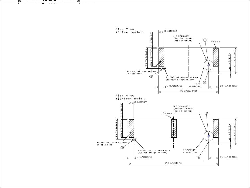
CVW-EXA184 / CVW-EXA124
2.3 External Dimensions |
2.4 Footprint |
* Dimensions given in inches and millimeters (mm in parentheses). |
|
Waste Outlet |
|
|
Electrical Connection |
||
|
|||
|
|
Refrigeration Outlet |
|
|
|
|

3 Unloading and Carpentry Procedures
3.1NSF Certification
The SANYO Cases described in this manual are built to meet the requirements of American National Standard/NSF International Standard 7. Each SANYO Case bears a nameplate identifying the type of application for which it was certified:
Type I display refrigerator/freezer: Intended for use in an area where the environmental conditions are controlled and maintained so that the ambient temperature typically does not exceed 75°F.
3.2Location
As noted above, the SANYO Cases described in this manual are design for the display of products in interior spaces with climate control, with ambient conditions typically maintained below 75°F and 55% relative humidity. Proper SANYO Case performance cannot be guaranteed when ambient temperature and/or humidity exceed this level.
SANYO Cases should not be exposed to direct sunlight or other sources of heat.
SANYO Cases should not be exposed to strong air currents, as these may disrupt the dual air curtains used to maintain proper temperature inside the merchandiser display area.
3.3Shipping Damage
All SANYO Cases and peripheral equipment should be examined for shipping damage prior to and during offloading. All SANYO Cases and peripheral equipment goes through outgoing inspection upon leaving our warehouse, and the carrier assumes responsibility for the safe arrival of our merchandisers.
APPARENT DAMAGE: Any obvious loss or damage should be noted immediately at the time of receipt on the freight bill or express receipt and signed by the carrier’s agent. Failure to do so may lead to rejection of the claim by the carrier.
CONCEALED DAMAGE: If damage that is not apparent during unloading is found after unpacking, retain all packing materials and submit a written request to the carrier for inspection within 15 days.
LOST ITEMS: Any claims related to lost or missing items must be made to SANYO North America Corporation, Commercial Solutions Division within 48 hours of receipt of equipment.
3.4Unloading Instructions & Precautions
 WARNING
SANYO Cases are heavy and bulky, and require at least two people for unloading, moving, and installation.
Do not remove the wooden beam from the bottom front edge of each SANYO Case until the cases have been moved into place in the store lineup.
Do not walk on the top of the SANYO Cases. Walking on the top of the SANYO Case may lead to serious injury and/or damage to the SANYO Case.
Do not place anything on the top of the SANYO Case or use the top of any SANYO Case for shortor long-term storage.
Recommended Practices for Unloading Merchandisers:
1.Use a J-Bar (Johnson Bar) to lift one end of the SANYO Case.
2.Insert one or more dollies under the base leg.
3.Lift the other side with the J-bar.
4.(Optional) Insert one or more dollies.
5.Move the SANYO Case out of container.
6.Use dollies on both ends of the SANYO Case to move to lineup location after unloading from container.
9
 Loading...