

Samsung YP-K3 AB, YP-K3 QB, YP-K3 ZB, YP-K3 Service Manual
PORTABLE DIGITAL AUDIO PLAYER
- Confidential -
SERVICE
Manual
Features
PORTABLE DIGITAL AUDIO PLAYER
Basic Model : YP-K3
* Application : YP-K3 ZB/ K3JZB [1GB]
YP-K3 QB/ K3JQB [2GB]
YP-K3 AB/ K3JAB [4GB]
Model :YP-K3
- Touchpad
- Easy & Simple Menu Structure
- Longer Play Time and Shorter
Downloading!
- Supporting Various File Formats!
- Convenience

ELECTRONICS
© Samsung Electronics Co.,Ltd.Dec. 2006
Ch13 Circuit Description
1-1. MICOM IC Block 13-1
1-2. Memory SDRAM Block 13-2
1-3. LCD, KEY, LED Block 13-3
1-4. USB/MODE Block 13-4
1-5. AUDIO Block 13-5
1-6. System Power Block 13-6
1-7. FM Tuner Block 13-7
Ch12 Schematic Diagram
1-1. MICOM 12-1
1-2. MEMORY 12-2
1-3. LCD/KEY/LED 12-3
1-4. USB/MODE/DET 12-4
1-5. AUDIO 12-5
1-6. POWER 12-6
1-7. FM/RTC 12-7
2-1. Major YP-K3 Wavef orms 12-8
Ch1 Precautions
1-1. Safety Precautions 1-1
1-2. Servicing Precautions 1-2
1-3. Precautions for Electrostatically
Sensitive Device (ESDs) 1-3
1-4. Special Precations and Waring
Lables for Laser Products 1-3
INDEX
Ch3 Product Functions
1. Basic Functions 3-1
2. New Functions 3-2
3. PC Connections 3-4
Ch4 Adjustments
1. How to recover the system 4-1
2. How to upgrade Firmware 4-3
Ch5 How to disassemble
How to disassemble 5-1
Ch7
Exploded View & Par ts List
1.Total Exploded View 7-1
2. Parts List 7-2
Ch8 Electrical Parts List
Electrical Parts List 8-1
Ch9 Block Diagram
Block Diagram 9-1
Ch10 Wiring Diagram
Wiring Diagram 10-1
Ch11 PCB Diagram
1.TOP Vie w 11-1
2. BOTTOM View 11-2
Ch14
Basic Information of MP3
1. Operating Principle of yepp 14-1
2. MP3 Overview 14-5
3.
Understanding of Digital Audio For mat
14-6
4.Type of Storage 14-9
5. Copyright 14-10
Ch2 Product Descriptions
1. Product Feature 2-1
2. Specifications 2-2
3. Accessories 2-3
Ch6 Troubleshooting
1. Power Failure 6-1
2. No Sound 6-2
3. Button Operation Failed 6-3
4. PC Connection Failed 6-4
5. Character Display on the LCD Failed 6-5
1. Precautions
Follow these safety, servicing and ESD precautions to prevent damage and protect against potential hazards such as electrical shock and X-rays.
Samsung Electronics1-1
1-1 Safety Precautions
1. Be sure that all of the built-in protective
devices are replaced.
2. When reinstalling the chassis and its
assemblies, be sure to restore all protective
devices, including control knobs and
compartment covers.
3. Make sure that there are no cabinet
openings through which people-particularly children--might insert fingers
and contact dangerous voltages. Such
openings include the spacing between the
picture tube and the cabinet mask,
excessively wide cabinet ventilation slots,
and improperly fitted back covers.
4. Design Alteration Warning:
Never alter or add to the mechanical or
electrical design of the unit. Example: Do
not add auxiliary audio or video connectors.
Such alterations might create a safety hazard. Also, any design changes or additions
will void the manufacturer's warranty.
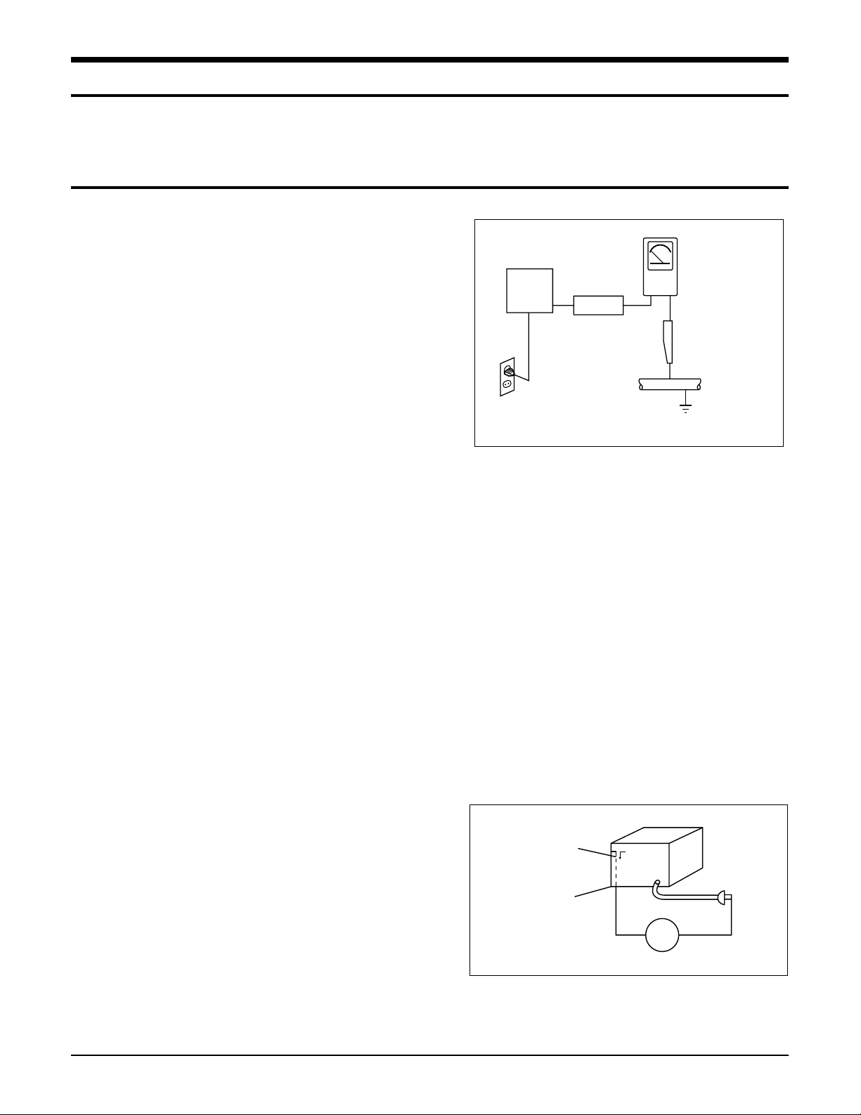
5. Leakage Current Hot Check (Figure 1-1):
Warning: Do not use an isolation
transformer during this test. Use a leak-
age-current tester or a metering system
that complies with American National
Standards Institute (ANSI C101.1, Leakage
Current for Appliances), and Underwriters
Laboratories (UL Publication UL1410,
59.7).
With the unit completely reassembled, plug
the AC line cord directly into a 120V AC
outlet. With the unit's AC switch first in the
ON position and then OFF, measure the
current between a known earth ground
(metal water pipe, etc.) and all exposed
metal parts. Examples: Handle brackets,
metal cabinets, screwheads and control
shafts. The current measured should not
exceed 0.5 milliamp. Reverse the powerplug prongs in the AC outlet and repeat.
6. Insulation Resistance Cold Check:
(1) With the unit's AC plug disconnected
from the AC source, connect an electrical
jumper across the two AC prongs. (2) Set
the power switch to ON. (3) Measure the
resistance between the shorted AC plug and
any exposed metallic parts. Example:
Screwheads, antenna, control shafts or
handle brackets.
If any of the exposed metallic parts has a
return path to the chassis, the measured
resistance should be between 1 and 5.2
megohms. If there is no return path, the
measured resistance should be "infinite." If
the resistance is outside these limits, a
shock hazard might exist. See Figure 1-2
Device
Under
Test
(Reading should
not be above
0.5mA)
Leakage
Currant
Tester
Earth
Ground
Test all
exposed metal
surfaces
Also test with
plug reversed
(using AC adapter
plug as required)
2-Wire Cord
Antenna
Terminal
Exposed
Metal Part
ohm
Ohmmeter
Fig. 1-1 AC Leakage Test
Fig. 1-2 Insulation Resistance Test

Samsung Electronics 1-2
1-1 Safety Precautions (Continued)
7. Components, parts and wiring that appear
to have overheated or that are otherwise
damaged should be replaced with parts
that meet the original specifications.
Always determine the cause of damage or
overheating, and correct any potential
hazards
8. Observe the original lead dress, especially
near the following areas: Antenna
wiring, sharp edges, and especially the
AC and high voltage power supplies.
Always inspect for pinched, out-of-place,
or frayed wiring. Do not change the
spacing between components and the
printed circuit board. Check the AC
power cord for damage. Make sure that
no wires or components touch thermally
hot parts.
9. Product Safety Notice:
Some electrical and mechanical parts
have special safety-related characteristics
which might not be obvious from visual
inspection. These safety features and the
protection they give might be lost if the
replacement component differs from the
original--even if the replacement is rated
for higher voltage, wattage, etc.
10 Components that are critical for safety are
indicated in the circuit diagram by
shading, or . Use replacement
components that have the same ratings,
especially for flame resistance and
dielectric strength specifications. A
replacement part that does not have the
same safety characteristics as the original
might create shock, fire or other hazards.
1-2 Servicing Precautions
1. Servicing precautions are printed on the
cabinet. Follow them.
2. Always unplug the unit's AC power cord from
the AC power source before
attempting to: (a) Remove or reinstall any
component or assembly, (b) Disconnect an
electrical plug or connector, (c) Connect a
test component in parallel with an
electrolytic capacitor.
3. Some components are raised above the
printed circuit board for safety. An
insulation tube or tape is sometimes used.
The internal wiring may be clamped to
prevent contact with thermally hot
components. Reinstall all such elements to
their original position.
4. After servicing, always check that the
screws, components and wiring have been
correctly reinstalled. Make sure that the
portion around the serviced part has not
been damaged.
5. Check the insulation between the blades of
the AC plug and accessible conductive parts
(examples: metal panels, input terminals
and earphone jacks).
6. Insulation Checking Procedure: Disconnect
the power cord from the AC source and
turn the power switch ON. Connect an
insulation resistance meter (500V) to the
blades of the AC plug.
The insulation resistance between each
blade of the AC plug and accessible
conductive parts (see above) should be
greater than 1 megohm.
7. Never defeat any of the B+ voltage
interlocks. Do not apply AC power to the
unit (or any of its assemblies) unless all
solid-state heat sinks are correctly installed.
8. Always connect a test instrument's ground
lead to the instrument chassis ground
before connecting the positive lead; always
remove the instrument's ground lead last.
Precautions
Warning1: First read the "Safety Precautions" section of this manual. If some unforeseen circumstance
creates a conflict between the servicing and safety precautions, always follow the safety precautions.

Samsung Electronics1-3
1-3 Precautions for Electrostatically Sensitive Devices (ESDs)
1-4 Special Precautions and Warning Labels for Laser Products
1. Some semiconductor ("solid state") devices
are easily damaged by static electricity.
Such components are called Electrostatically
Sensitive Devices (ESDs). Examples
include integrated circuits and some fieldeffect
transistors. The following techniques will
reduce the occurrence of component
damage caused by static electricity.
2. Immediately before handling any
semiconductor components or assemblies,
drain the electrostatic charge from your
body by touching a known earth ground.
Alternatively, wear a discharging
wrist-strap device. (Be sure to remove it
prior to applying power--this is an electric
shock precaution.)
3. After removing an ESD-equipped assembly,
place it on a conductive surface such as
aluminum foil to prevent accumulation of
electrostatic charge.
4. Do not use freon-propelled chemicals.
These can generate electrical charges that
damage ESDs.
5. Use only a grounded-tip soldering iron
when soldering or unsoldering ESDs.
6. Use only an anti-static solder removal
device. Many solder removal devices are
not rated as "anti-static" (these can
accumulate sufficient electrical charge to
damage ESDs).
7. Do not remove a replacement ESD from its
protective package until you are ready to
install it. Most replacement ESDs are
packaged with leads that are electrically
shorted together by conductive foam,
aluminum foil or other conductive
materials.
8. Immediately before removing the protective
material from the leads of a replacement
ESD, touch the protective material to the
chassis or circuit assembly into which the
device will be installed.
9. Minimize body motions when handing
unpackaged replacement ESDs. Motions
such as brushing clothes together, or lifting
a foot from a carpeted floor can generate
enough static electricity to damage an ESD.
Precautions
UL : Manufactured for U.S.A. Market.
CSA : Manufactured for Canadian Market.
EU : Manufactured for European Market.
SCAN : Manufactured for Scandinavian
Market.
This Product Complies with
DHHS Rules 21CFR, Sub
chapter J.At date of Manufacture
(UL)
(UL,CSA,SCAN)
(EU)
CERTIFIED ONLY TO CANADIAN
ELECTRICAL CODE.
CERTIFIE EN VERTU DU CODE
CANADIAN DE LELETRICITE
SEULEMENT
(CSA)
CLASS 1
LASER PRODUCT
(UL,CSA,EU)
Fig. 1-3 Warning Labels (Location: Enclosure Block)
Fig. 1-4 Warning Labels (Location: Disc Clamper, Inner Side of Unit Door or Nearby Unit Chassis )
CAUTION : INVISIBLE LASER RADIATION WHEN OPEN
AND INTERLOCKS DEFEATEO AVOIDEXPOSURE TO BEAM
ADVARSEL:USYNLIG LASERSTRÅLING VED ABNING
NÅR SIKKERHEDSAFBRYDERE ER UDE AF FUNKTION
UNDGA UDSAETTELSE FOR STRALING
VARO:AVATTAESSAJA SUOJALUKITUS OHITETTAESSA
OLETALTTINANAKYMATTÖMALLE LASERSATEILYLLE ALA
KATSO SATEESEEN!
VARNING:OSYNLIG LASERSTRÅLNING NAR DENNADEL
AR OPPNAD OCH SPARREN AR URKOPPLAD BETRAKTA
EJSTRÅLEN!
Samsung Electronics 1-4
1-4 Special Precautions and Warning Labels for Laser Products (Continued)
1-4-1 Warnings
1. When servicing, do not approach the
LASER exit with the eye too closely. In
case it is
necessary to confirm LASER beam emis-
sion, be sure to observe from a distance of
more than 30 cm from the surface of the
objective lens on the optical pick-up block.
2. Do not attempt to handle the objective lens
when the DISC is not on the tray.
1-4-2 Laser Diode Specifications
Material: GaAs+ GaAlAs
Wavelength: 760-800 nm
Emission Duration: Continuous
Laser Output: 0.2 mw (measured at a
1.6 mm distance from the objective lens
surface on the optical pick-up block.)
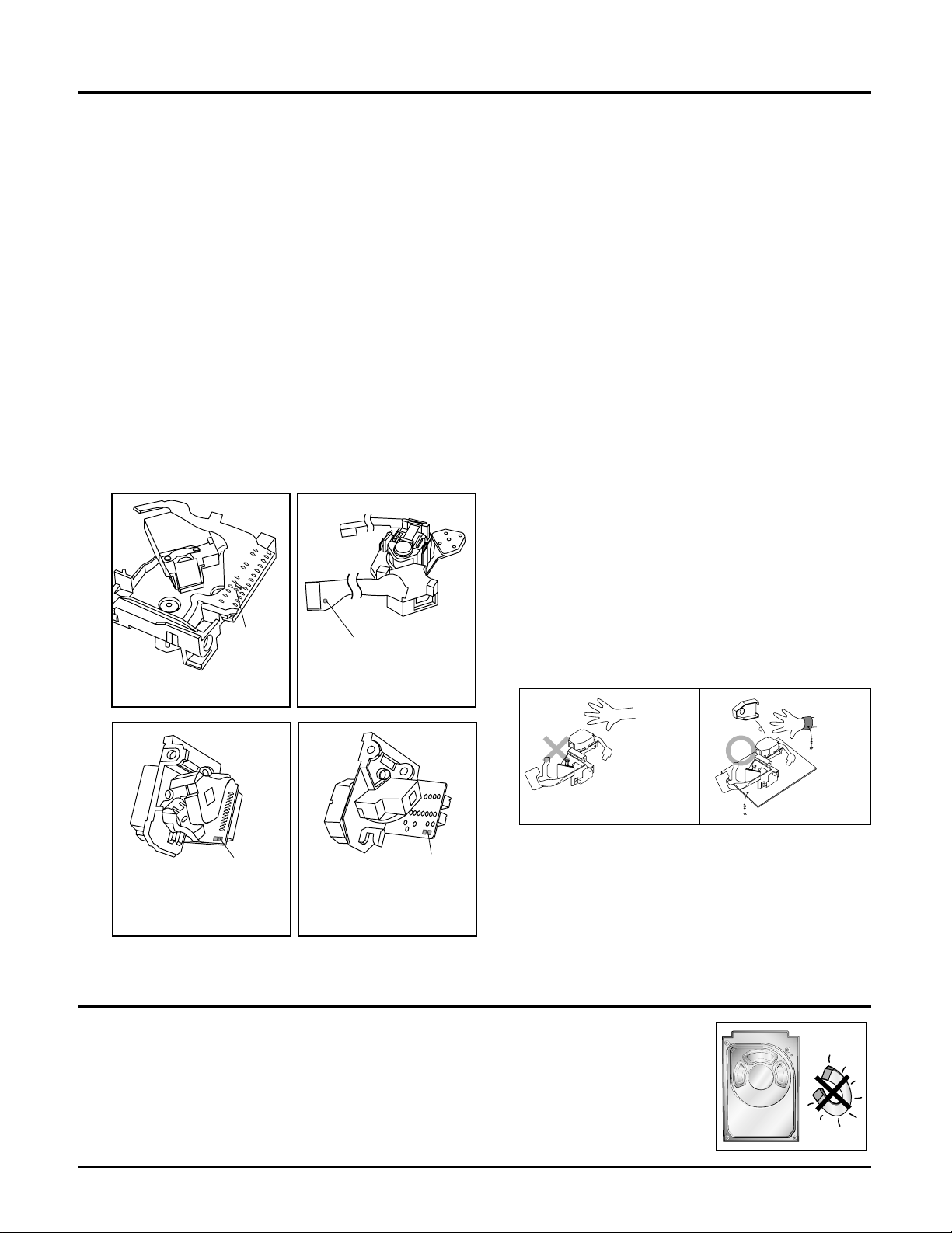
1-4-3 Handling the Optical Pick-up
1. Static electricity from clothing or the body
may cause electrostatic breakdown of the
laser diode in the Optical Pickup. Follow
this procedure:
2. Place a conductive sheet on the work bench
(i.e., the black sheet used for wrapping
repair parts.) Note: The surface of the work
bench should be covered by a copper
ground plane, which is grounded.
3. The repair technician must wear a wrist
strap which is grounded to the copper
sheet.
4. To remove the Optical Pickup block:
Place the set on the conductive sheet, and
momentarily touch the conductive sheet
with both hands. (While working, do not
allow any electrostatic sources--such as
clothes--to touch the unit.)
5. Ground the "Short Terminal" (located on the
PCB, inside the Pickup Assembly) before
replacing the Pickup. This terminal should
be shorted whenever the Pickup Assembly
is lifted or moved.
6. After replacing the Pickup, reopen the Short
See diagrams below:
Precautions
THE UNIT
(1) WRIST-STRAP
FOR GROUNDING
1-5 Special Precautions for HDD
* HDD Data Maintenance Step
1. Since the data on the HDD is weak to mechanical shock, place the HDD in a safe
location that is free from mechanical shock once it is removed from the main unit.
2. In order to safe keep the data on the HDD, back up the data before the repair or
make sure not to place the HDD near any electrical appliance that generates a
strong magnetic field.
short
terminal
SOH91VI(LDP)
short terminal
SOH91CI(CAR,walkman)
1M
CONDUCTIVE SHEET
short
terminal
SOH-A1
(CMS-V10,CMS-V30)
short
terminal
SOH94T4N
(CMS-V10,CMS-V30)
1M
2. Product Descriptions
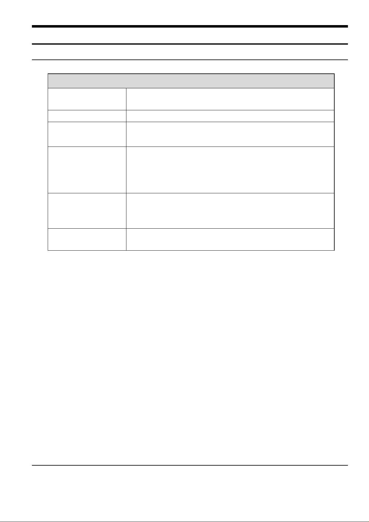
1. Product Feature
Product Feature
High-quality Stereo
Speaker!
Touchpad
Easy & Simple Menu
Structure
Longer Play Time and
Shorter Downloading!
Supporting Various File
Formats!
Convenience
■
You can share your favorite music anytime and anywhere.
■
You can tap on the touch pad to navigate through the menus.
■
Easy to use with a simple menu structure.
■
A fully charged battery can play up to 30 hours of music
(when using the earphone).
■
The player supports USB 2.0 capability, much faster than USB 1.1 to
enable faster communication with the PC.
■
Supports various file formats including MP3, WMA and Ogg.
■
The image file is converted to JPG format before transmitted to the
player.
■
You can take advantage of a var iety of features including FM radio,
photo view, etc.
2-1 Samsung Electronics
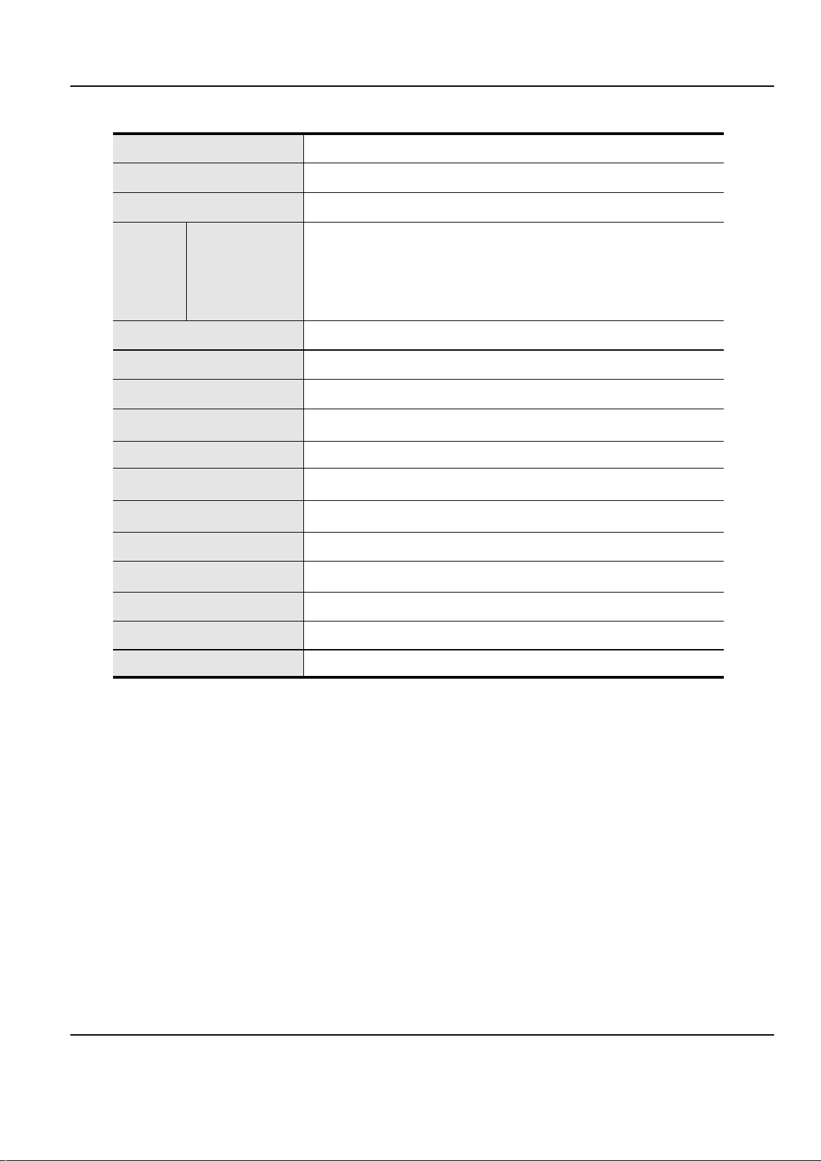
2. Specifications
Samsung Electronics 2-2
Model Name
Power
Built-in Battery Power
Earphone Output
Output Frequency Range
Noise Ratio
Play Time
Temperature Range for Operation
Case
Weight
Dimension (WxHxD)
FM Frequency
FM Signal to Noise Ratio
FM T.H.D
FM Useable Sensitiivity
File
Compatibility
YP-K3
3.7V (Li-Polymer Rechargeable)
470mAh
Music : MPEG1/2/2.5 Layer3(8kbps~320kbps, 22kHz~48kHz)
WMA(48kbps~192kbps, 22kHz~48kHz), Ogg(Q0~Q10)
Image : JPEG(ISO/IEC 10918-1/Annex F-Sequential DCT-based mode
of operation)
15mW(16Ω)
20Hz~20KHz
88 dB with 20kHz LPF(based on 1KHz 0 dB)
Music 20 hrs (based on MP3 128kbps, volume level 15 and normal mode)
-5~35
°C
(23~95°F)
Stainless, Plastic
1.76 oz (50g)
1.73 X 3.78 X 0.27 inches (44 X 96 X 6.95 mm)
87.5~108.0MHz
50dB
1%
38dBµ
●
The contents of this Manual are subject to change without prior notice for further
improvement.
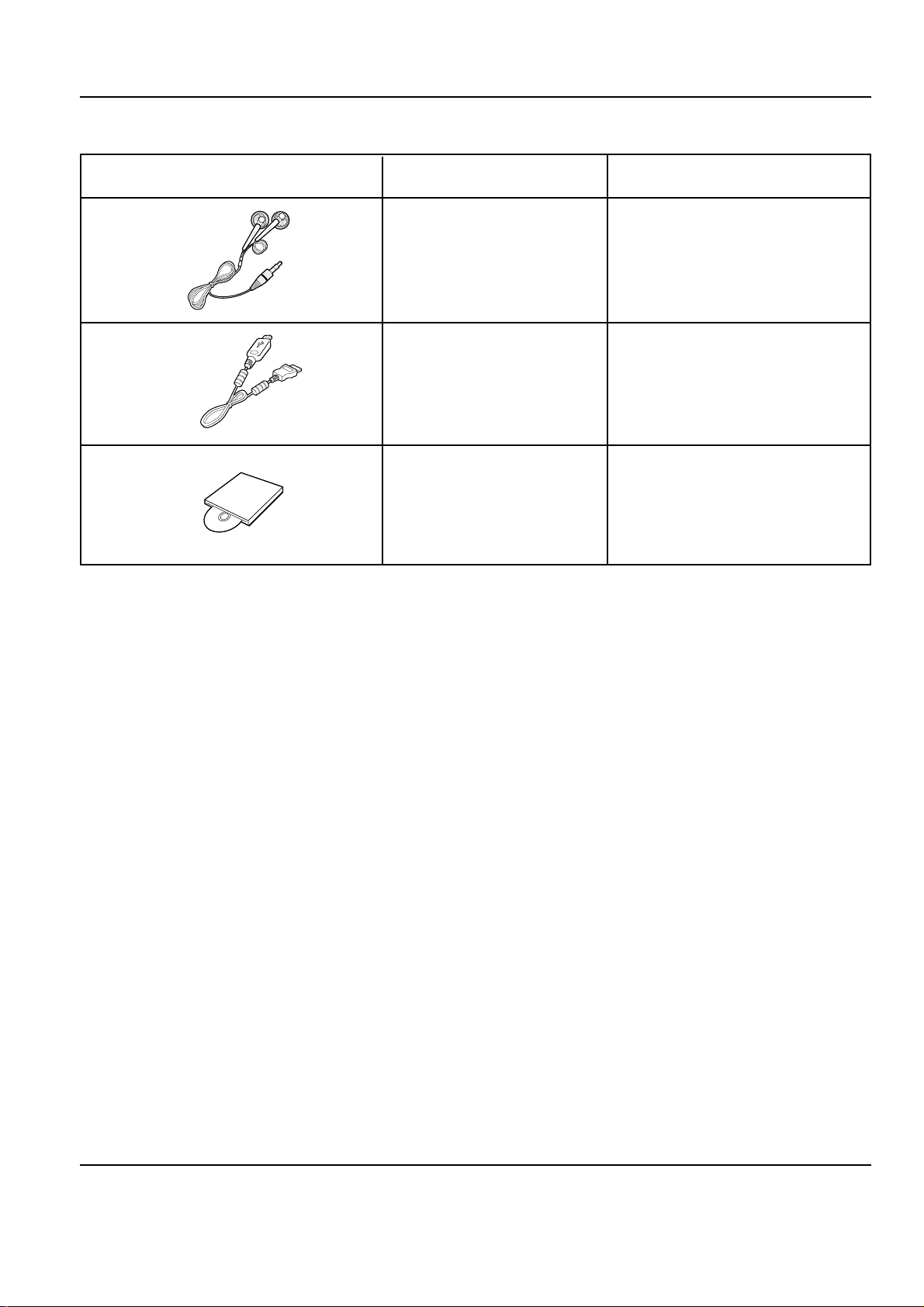
Accessories Name Code No.
3. Accessories
2-3 Samsung Electronics
AH30-00087D
Earphones
AH39-00899A
USB Cable
AH80-00139B
Installation CD
Samsung Electronics 3-1
3. Product Functions
1. Basic Functions
Music
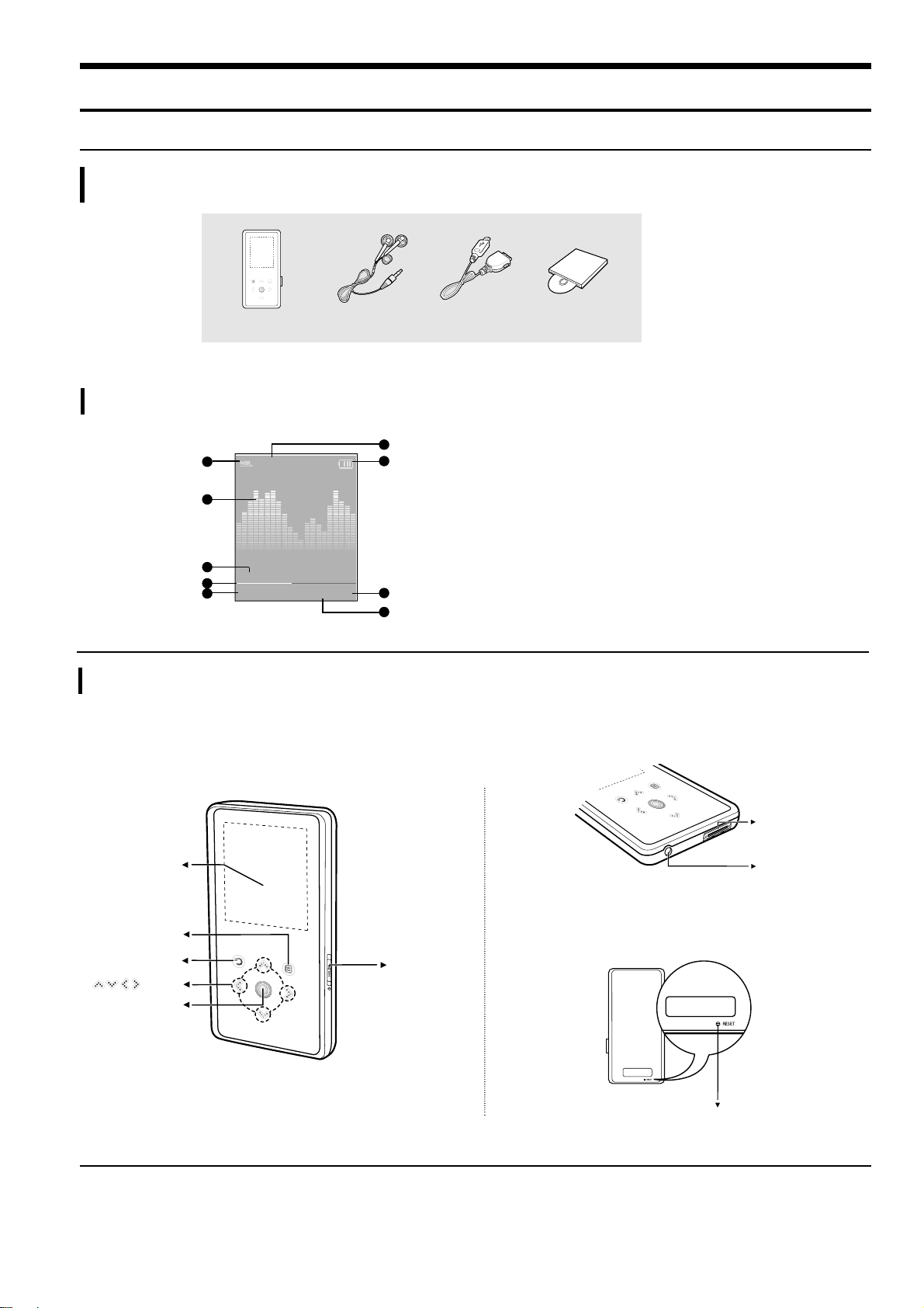
Checking the Accessories
Components
Front, Right Side Bottom
Rear
Player Earphones USB Cable
Installation CD
Normal
1.Life is cool
002/020
√√
00:02:20
1
2
3
4
5
6
7
8
9
1 Play Mode Display
2 Graphic Equalizer
3 Music Information
4 Play Status Bar
5 Current Music Number/
Total Number Display
6 Sound Effect Display
7 Battery Status Display
8 Play Time Display
9 Play/Pause Display
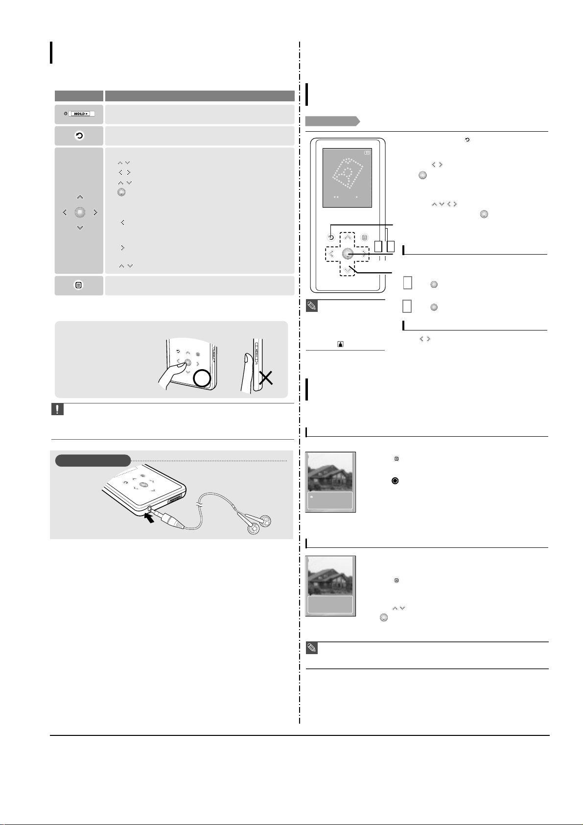
Power &
Hold Switch
Screen Display
Back Button
Play/Pause &
Select Button
Menu Button
Button
USB
Connection
Port
Earphone
Jack
Reset Hole
2. New Functions
3-2 Samsung Electronics
CAUTION
■
Do not use any sharp object other than your fingers to operate the touch screen.
Otherwise, touch screen may be damaged.
■
Do not tap on the touch screen if your fingers are not clean.
■
Do not tap on the touch screen with your gloves on.Otherwise, the button does not operate in any way.
✽
Tap on touch screen with your
fingertip.
Earphone Connection
√ Bottom
Earphones
Button Functions
Basic Information
■
Slide and hold in the opposite direction of the arrow to turn the power on/off.
■
Slide in the arrow direction to lock the buttons.
■
Moving up, down, left and right and Function Selection.
Tap to move up or down by one selection.
Tap to move left or right by one selection.
Press and hold to move up or down continuously.
Short tap to select the play/pause and function, move to the
next screen.
■
Search for a track and control volume while listening to music.
Press and hold to scan to a point on the current track.
Tap to move to the previous track or to play the current track
from the start.
Press and hold to scan to a point on the current track.
Tap to move to the next track.
Tap to reduce/increase the volume.
■ Long tap to move to the main menu.
■
Short tap to move to the previous screen.
Buttons Functions and Use
■
Tap to display the option menu.
1
2,3
1,2
1
Press and hold [ ] to move to the main
menu.
2
Tap [ ] to select <Photo> and then tap
[].
■
The Photo list will appear.
3
Tap [ ] to select the photo file of
your choice, then tap [ ].
■
The selected file will appear.
■
Large photos may take longer to display.
1
Tap [ ] in Photo Viewing mode.
■
The slideshow will start.
You can view your picture files in order as a
Slideshow.
2
Tap [ ] to stop the slideshow.
Slideshow Viewing
Tap [ ].
■
You can see the previous or next photo on the display.
To view the previous / next photo
NOTE
■
You will see thumbnail
photos if the appropriate
information is included in
the file.
For a file with no
information, you will
see instead.
Photo Viewing
Photo Viewing
Before you start!
See pages 20-21 to transfer Photo files to your player.
Photo
To add a photo to the screen saver list
To listen to music while viewing your photo
1
Select a photo file that you want to add to the screen saver list.
2
Tap [ ] while viewing a photo.
■
The photo option menu appears.
3
Tap [ ] to select <Add to Screen Saver> and then tap
[].
■
The selected photo file is added to the list.
1
Tap [ ] while viewing a photo.
■
The photo option menu appears.
You can listen to the song that you last played while viewing your photo.
2
Tap [ ] to select <Background Music On> or <Background
Music Off>.
■
<Background Music On> : You can listen to the song that you last
played while viewing your photo.
■
<Background Music Off> : No background music is played while
viewing a photo.
Using the Photo Option Menu
Photo Viewing
Background Mu..
Add to Screen S..
Background Mu..
Add to Screen S..
NOTE
■
Select <Photo> from <Settings> → <Display>→<Screen Saver> and the selected photo is
displayed on the screen as a screen saver.
■
If you set <Default Set>, the screen saver will be initialized to <Analog Clock>.
Samsung Electronics 3-3
1
2
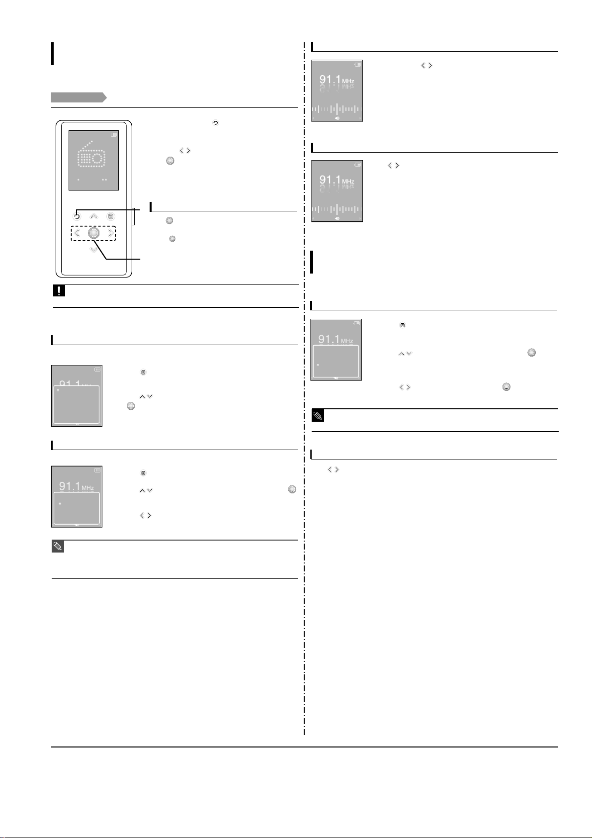
Listening to FM Radio
Listening to FM Radio
Before you start!
Connect the earphones, then turn on the player, and check the battery.
1
Press and hold [ ] to move to the main
menu.
2
Tap [ ] to select <FM Radio> and then tap
[].
■
FM radio reception will start.
Tap [ ] while listening to the FM radio.
■
Sound is muted.
■
Tap [ ] once again to hear sound.
To use Mute function
■
Always connect your earphones to the player when searching or setting frequencies.The earphones are
used as antennas to receive FM radio reception.
CAUTION
FM Radio
To switch to Preset Mode
To switch to Manual mode
1
Tap [ ] in <Manual Mode>.
2
Tap [ ] to select <Go to Preset Mode> and then tap [ ].
■
You will see <Preset Mode> on the screen.
3
Tap []to select the preset frequency.
■
Once <Preset Mode> appears on the screen, you can select a radio
frequency and listen to it.
1
Tap [ ] in <Preset Mode>.
Select this mode if you want to manually search through the FM band one frequency
at a time.
Select this mode if you want to search through your saved FM presets one preset at a time .
2
Tap [ ] to select <Go to Manual Mode> and then tap
[].
■
You will see <Manual Mode> on the screen.
NOTE
■
If no preset frequencies are set, you will see <Preset list does not exist.> and the player will not
switch to <Preset Mode>.
■
If you set <Default Set>, the saved preset lists are deleted.
■
If you select <Preset List> on the FM option menu, you will see the preset frequencies.
■
For more information on the preset setup.
Go to Manual ..
Delete Preset
Auto Preset
Preset List
FM Sensitivity
Preset Mode
Go to Preset ..
Add Preset
Auto Preset
FM Sensitivity
Manual Mode
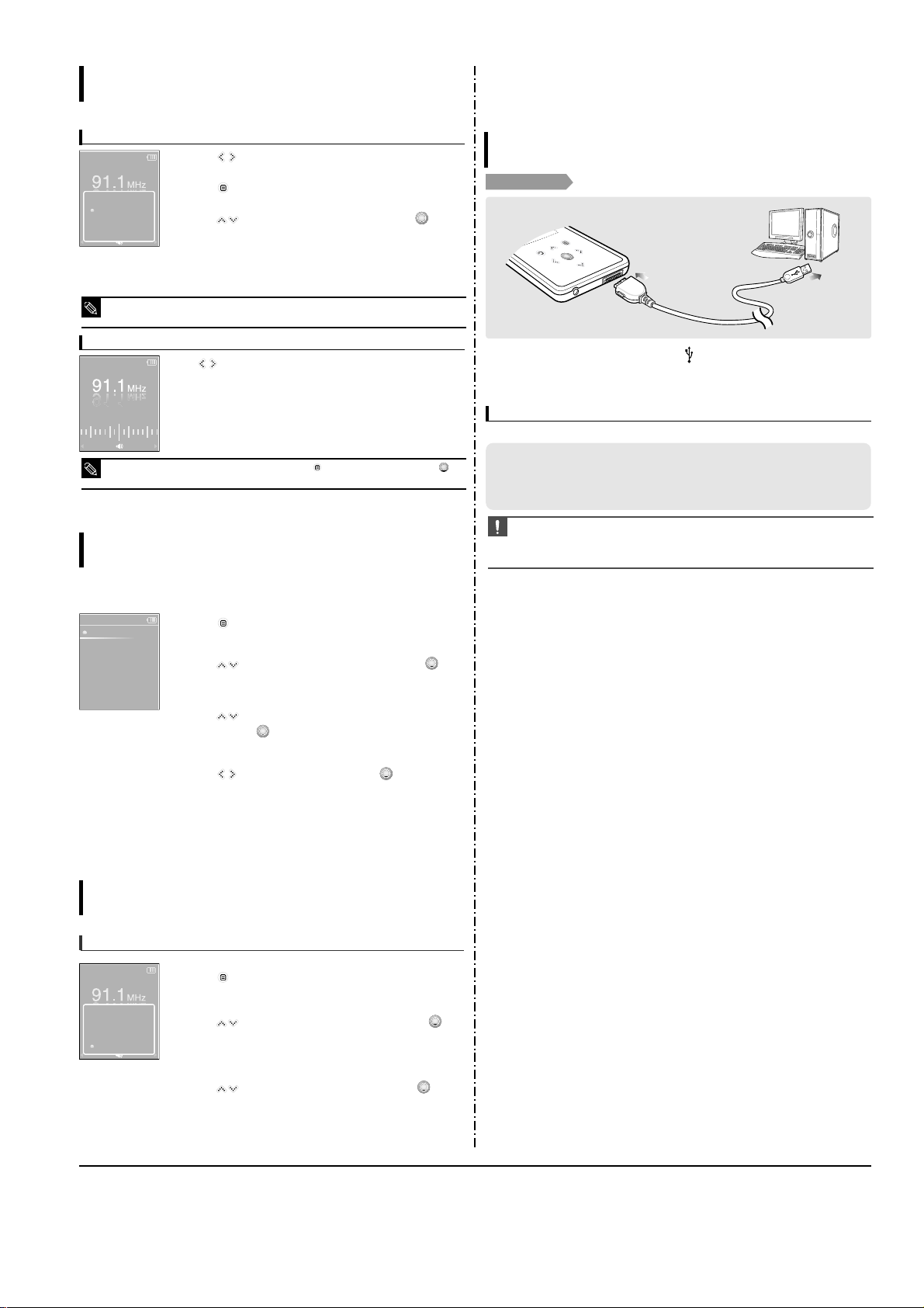
To manually search for frequencies
To automatically search for frequencies
Press and hold []in <Manual Mode>.
■
The broadcast station frequency nearest from the point the button is
released will be searched.
Tap []in <Manual Mode>.
■
Moves to next frequency whenever the button is tapped.
Manual Mode
Manual Mode
To automatically set Presets
1
Tap [ ] in FM Radio mode.
2
Tap [ ] to select <Auto Preset> and then tap [ ].
■
You will see the Auto Preset window on the screen.
3
Tap [ ] to select <Yes> and then tap [ ].
■
Up to 30 presets are automatically saved.
Setting FM Presets
Listening to FM Radio
You can set up to 30 presets in FM Radio mode.
To cancel during setting
Tap [ ] to cancel during auto scanning.
■
The auto preset setting is canceled and frequencies set up to then are stored.
■
Using <Auto Preset> deletes all previous presets.
NOTE
Go to Preset ..
Add Preset
Auto Preset
FM Sensitivity
Manual Mode
3-4 Samsung Electronics
3. PC Connection
To manually set Presets
To search for presets in Preset mode
1
Tap [ ] to select the desired frequency in <Manual Mode>.
2
Tap [ ].
3
Tap [ ] to select <Add Preset> and then tap [ ].
■
The selected frequency will be added to the preset list. A maximum of
30 preset numbers are added to the list in sequential order.
Tap []in <Preset Mode>.
■
The preset number is selected and you can listen to the stored radio
frequency.
4
To set a preset for other frequencies,follow 1-3 steps above.
■
If a frequency that you try to add already exists in the list, you will see <This preset already exists.> and
the selected frequency is not added to the preset list.
NOTE
■
If you want to check the preset list in <Preset Mode>, tap []to select <Preset List> and Tap [].
NOTE
Go to Preset ..
Add Preset
Auto Preset
FM Sensitivity
Manual Mode
Preset Mode
1
Tap [ ] in <Preset Mode>.
2
Tap [ ] to select <Delete Preset> and then tap [ ].
■
The preset frequencies will appear.
3
Tap [ ] to select the preset frequency you want to delete
and then tap [ ].
■
The confirmation window will appear.
4
Tap [ ] to select <Yes> and then tap [ ].
■
The selected preset will be deleted.
5
To select and delete other preset numbers, follow 1-4 steps
above.
To Delete Presets
Listening to FM Radio
89.1MHz
89.2MHz
89.3MHz
89.4MHz
Delete Preset
Listening to FM Radio
Setting FM Radio
To set FM Sensitivity
1
Tap [ ] in FM Radio mode.
2
Tap [ ] to select <FM Sensitivity> and then tap [ ].
■
The FM Sensitivity menu appears.
3
Tap [ ] to select the sensitivity and then tap [ ].
■
You can select from <High>, <Middle> and <Low>.
■
The higher FM sensitivity is, the more frequencies that can be received.
Go to Preset ..
Add Preset
Auto Preset
FM Sensitivity
Manual Mode
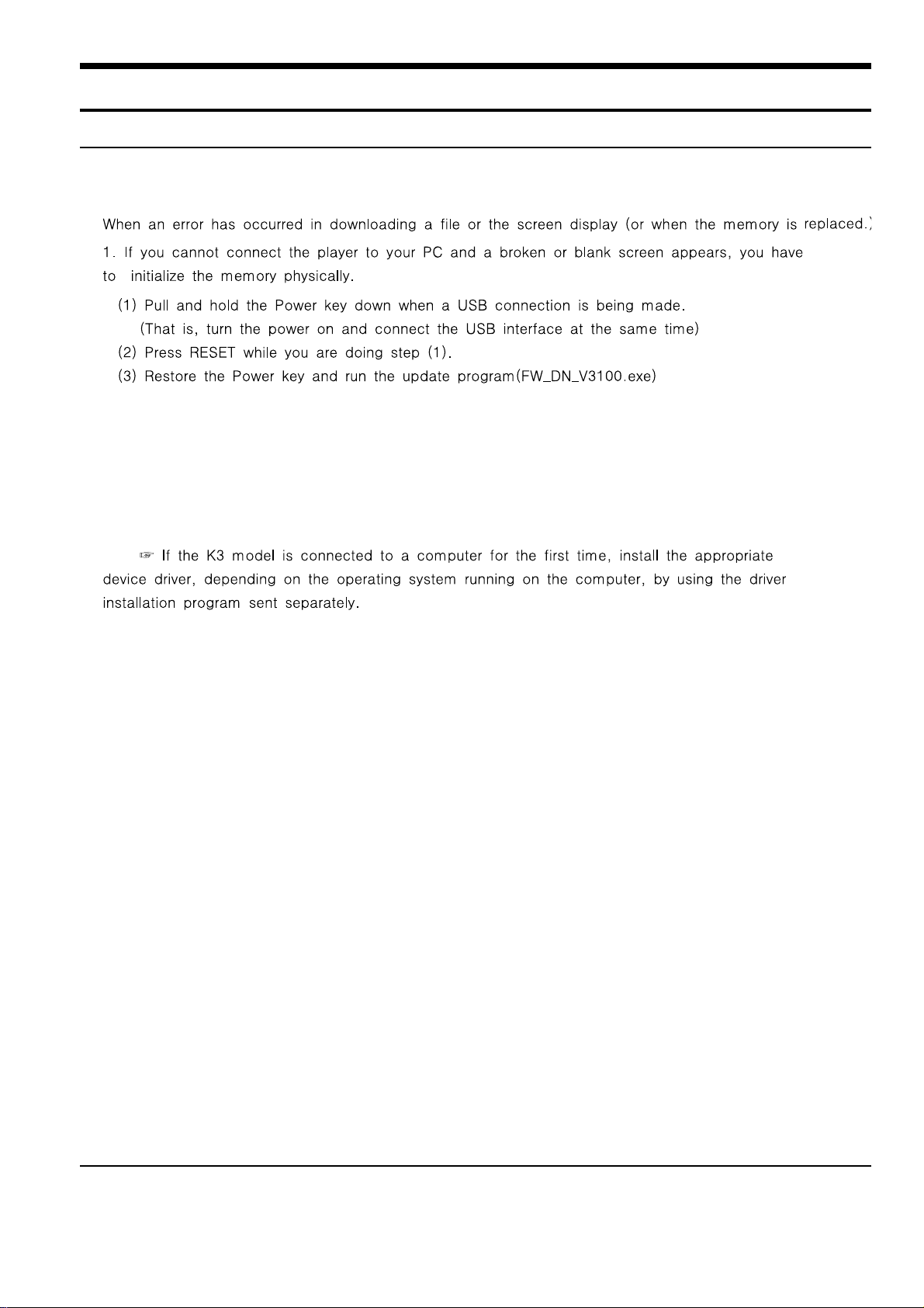
Connecting to your PC
Loading Your Desired File
Before you start!
Use the USB Cable provided when connecting the player to your PC.
1
1
Connect the USB cable to the USB port ( ) on your PC.
2
2
Connect the other end of the USB cable to the
USB Connection Port
on the
bottom of the player.
The PC system must meet the following minimum specifications:
■
Pentium 300MHz or higher
■
Windows 2000/XP
■
DirectX 9.0 or higher
■
USB Port 2.0
■
100MB of free hard disc space
■
CD Rom Drive (2X or higher)
■
Windows Media Player 10.0 or higher
■
Resolution 1024 X 768 or higher
PC Requirements
CAUTION
■
If you connect the player through a USB hub, the connection may be unstable. Please connect the
player to your PC directly.
■
If you connect the player to your PC in the low battery condition, the player automatically checks
the battery status and charges itself for several minutes before connecting to your PC.
Setting FM Presets
(Continued)
Listening to FM Radio
Samsung Electronics 4-1
Samsung Electronics
4. Adjustments
1.How to recover the device
4-2 Samsung Electronics
4-3
Samsung Electronics
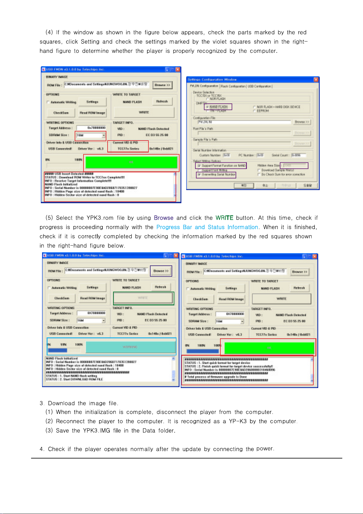
2. How to upgrade Firmware
4-4 Samsung Electronics

4-5
Samsung Electronics
5. How to disassemble
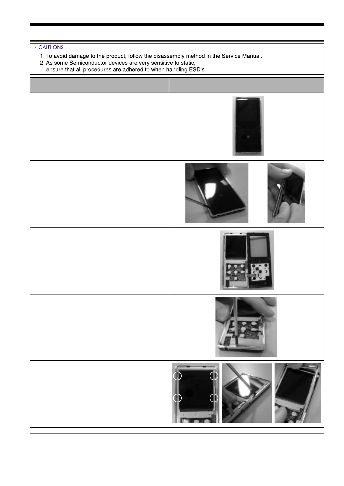
PictureOrder(Description)
1. Picture prior to disassembly
2. Open up the cover by inserting a
screwdriver or your fingernail into
the gap and separate the front
cover, which is fixed in place by double-sided tape.
3. Separate the FPCB of the Touch
Pad.
4. Remove the screws on the bottom
side of the player.
5.Through the 4 holes marked on the
figure, release the catch by pulling it
forward while opening it outwards.
5-1 Samsung Electronics
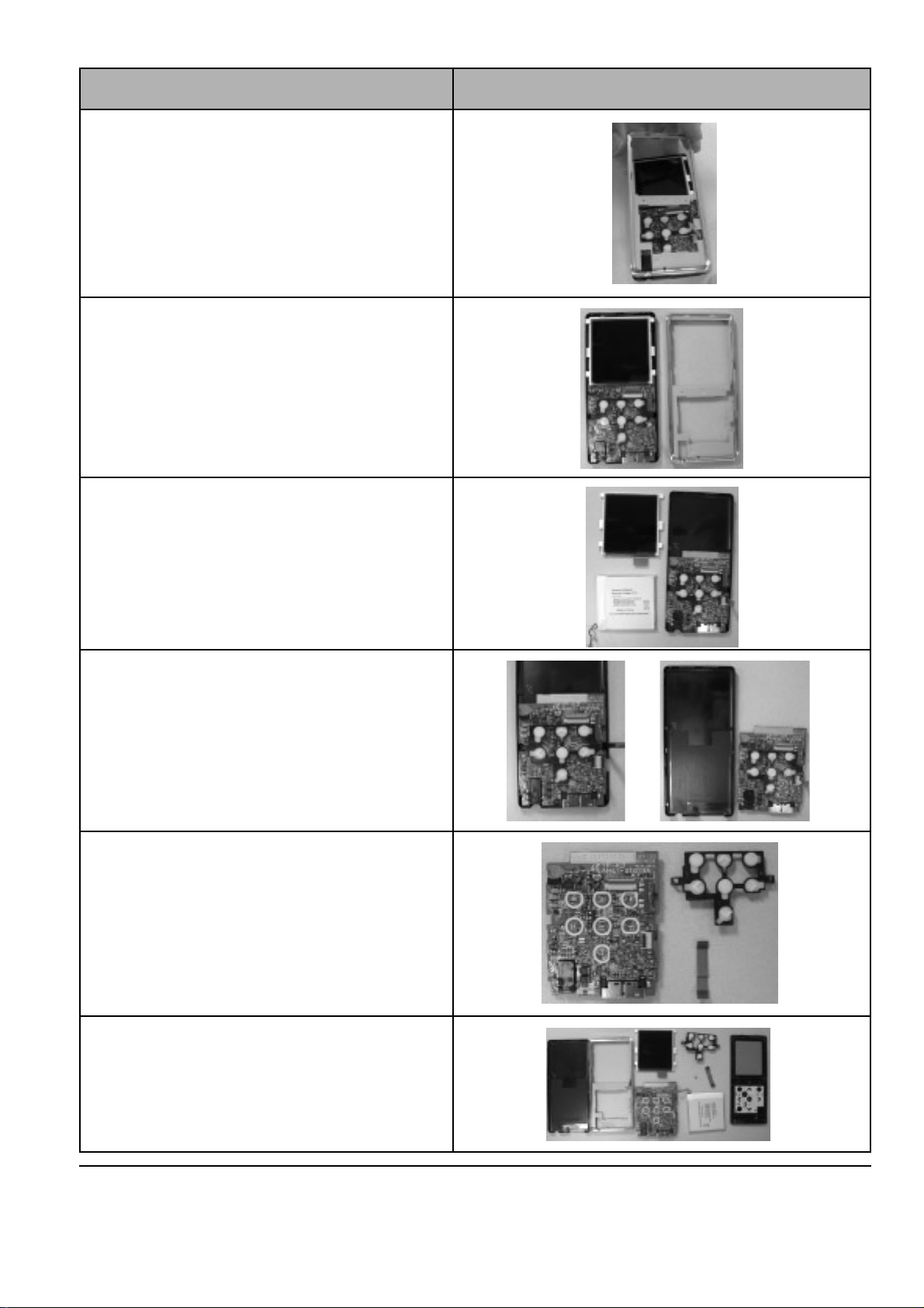
PictureOrder(Description)
6. Separate the Front-Cabinet.
7. In this step, the Front-Cabinet and
Back-Cabinet are easily bent out of
shape. If they are bent, it may no
longer be possible to use them.
8. Separate the OLED and battery.
9. Separate the Main PCB
10. Separate the Light-Holder and the
FPC
11. Picture after disassembly.
Samsung Electronics 5-2
 Loading...