

Samsung UA32F45 Series, UA32F53 Series, UA46F53 Series, UA46F55 Series, UA50F55 Series Service Manual
...
LED TV
SERVICE
Manual
LED TV Contents
1. Precautions
2. Product specications
3. Disassembly and Reassembly
4. Troubleshooting
5. Wiring Diagram
UA**F5500A*
Chassis : U85A
Model : UA32F45*0A*
UA**F53*0A*
UA**F55**A*

Contents
1. Precautions ...................................................................................................................1-1
1-1. Safety Precautions ..............................................................................................................1-1
1-2. Servicing Precautions ..........................................................................................................1-3
1-3. Static Electricity Precautions ...............................................................................................1-4
1-4. Installation Precautions .......................................................................................................1-5
2. Product Specications.................................................................................................2-1
2-1. Product Information .............................................................................................................2-1
2-2. Accessories .........................................................................................................................2-8
3. Disassembly and Reassembly ....................................................................................3-1
3-1. Disassembly and Reassembly ............................................................................................3-1
3-2. Assy Board P-Jog Switch & Ir ..............................................................................................3-6
3-3. Disassembly(PTC) ...............................................................................................................3-8
4. Troubleshooting ...........................................................................................................4-1
4-1. Troubleshooting ................................................................................................................... 4-1
4-2. How to Check Fault Symptom .............................................................................................4-3
4-3. Factory Mode Adjustments ................................................................................................ 4-21
4-4. White Balance ...................................................................................................................4-37
4-5. White Ratio (Balance) Adjustment .....................................................................................4-40
4-6. Detail Specications ..........................................................................................................4-42
4-7. Software Upgrade ............................................................................................................ 4-115
4-8. Rear Cover Dimension .................................................................................................... 4-118
5. Wiring Diagram .............................................................................................................5-1
5-1. Wiring Diagram .................................................................................................................... 5-1
5-2. Connector ...........................................................................................................................5-2
5-3. Connector Functions ...........................................................................................................5-6
5-4. Cables .................................................................................................................................5-7

This Service Manual is a property of Samsung Electronics Co.,Ltd.
Any unauthorized use of Manual can be punished under applicable
International and/or domestic law.
© 2013 Samsung Electronics Co.,Ltd.
All rights reserved.
Printed in Korea
Follow these safety, servicing and ESD precautions to prevent damage and to protect against potential hazards such as
electrical shock.
1-1-1. Warnings
WARNING
For continued safety, do not attempt to modify the circuit board.
Disconnect the AC power and DC power jack before servicing.
1-1-2. Servicing the LED TV
When servicing the LED TV, Disconnect the AC line cord from the AC outlet.1.
It is essential that service technicians have an accurate voltage meter available at all times. Check the calibration of this 2.
meter periodically.
1-1-3. Fire and Shock Hazard
Before returning the monitor to the user, perform the following safety checks:
Inspect each lead dress to make certain that the leads are not pinched or that hardware is not lodged between the 1.
chassis and other metal parts in the monitor.
Inspect all protective devices such as nonmetallic control knobs, insulating materials, cabinet backs, adjustment and 2.
compartment covers or shields, isolation resistorcapacitor networks, mechanical insulators, etc.
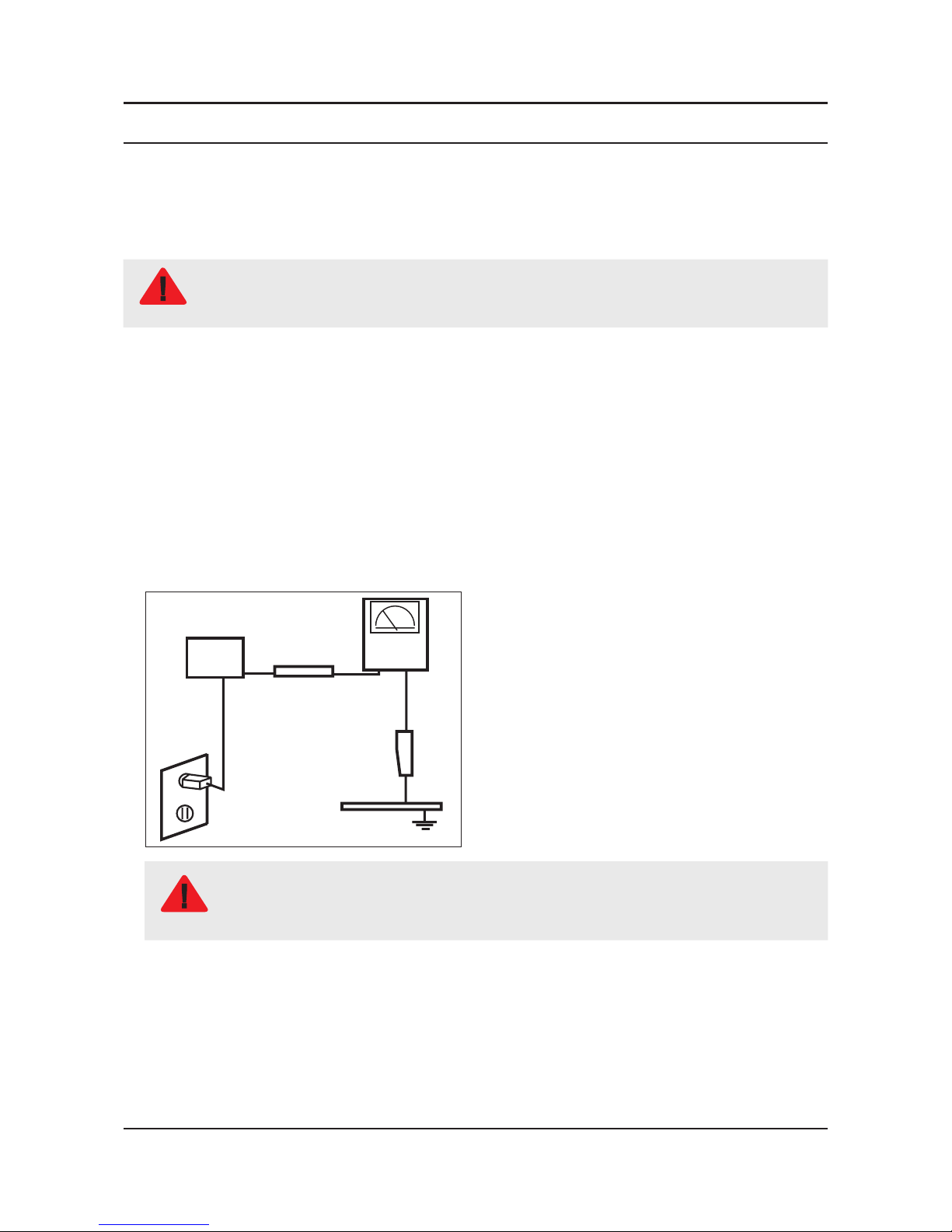
Leakage Current Hot Check:3.
DEVICE
UNDER
TEST
(READING SHOULD)
NOT BE ABOVE 0.5mA
LEAKAGE
CURRENT
TESTER
TEST ALL
EXPOSED METAL
SURFACES
2-WIRE CORD
ALSO TEST WITH
PLUG REVERSED
(USING AC ADAPTER
PLUG AS REQUIRED)
EARTH
GROUND
WARNING
Do not use an isolation transformer during this test.
Use a leakage current tester or a metering system that complies with American National Standards
Institute (ANSI C101.1, Leakage Current for Appliances), and Underwriters Laboratories (UL
Publication UL1410, 59.7).
With the unit completely reassembled, plug the AC line cord directly into a 120V AC outlet. With the unit’s AC switch rst 4.
in the ON position and then OFF, measure the current between a known earth ground (metal water pipe, conduit, etc.)
and all exposed metal parts, including: metal cabinets, screwheads and control shafts.
The current measured should not exceed 0.5 milliamp.
Reverse the power-plug prongs in the AC outlet and repeat the test.
1-1
1. Precautions
1. Precautions
1-1. Safety Precautions

1-2
1. Precautions
1-1-4. Product Safety Notices
Some electrical and mechanical parts have special safetyrelated characteristics which are often not evident from visual
inspection. The protection they give may not be obtained by replacing them with components rated for higher voltage,
wattage, etc. Parts that have special safety characteristics are identied by
on schematics and parts lists. A substitute
replacement that does not have the same safety characteristics as the recommended replacement part might create
shock, re and/or other hazards. Product safety is under review continuously and new instructions are issued whenever
appropriate.
WARNING
An electrolytic capacitor installed with the wrong polarity might explode.
CAUTION
Before servicing units covered by this service manual, read and follow the Safety Precautions section of
this manual.
NOTE
If unforeseen circumstances create conict between the following servicing precautions and any of the
safety precautions, always follow the safety precautions.
1-2-1. General Servicing Precautions
Always unplug the unit’s AC power cord from the AC power source and disconnect the DC Power Jack before 1.
attempting to: (a) remove or reinstall any component or assembly, (b) disconnect PCB plugs or connectors, (c) connect
a test component in parallel with an electrolytic capacitor.
Some components are raised above the printed circuit board for safety. An insulation tube or tape is sometimes used. 2.
The internal wiring is sometimes clamped to prevent contact with thermally hot components. Reinstall all such elements
to their original position.
After servicing, always check that the screws, components and wiring have been correctly reinstalled. Make sure that 3.
the area around the serviced part has not been damaged.
Check the insulation between the blades of the AC plug and accessible conductive parts (examples: metal panels, input 4.
terminals and earphone jacks).
Insulation Checking Procedure: Disconnect the power cord from the AC source and turn the power switch ON. Connect 5.
an insulation resistance meter (500 V) to theblades of the AC plug. The insulation resistance between each blade of the
AC plug and accessible conductive parts (see above) should be greater than 1 megohm.
Always connect a test instrument’s ground lead to the instrument chassis ground before connecting the positive lead; 6.
always remove the instrument’s ground lead last.
1-3
1. Precautions
1-2. Servicing Precautions
Some semiconductor (solid state) devices can be easily damaged by static electricity. Such components are commonly
called Electrostatically Sensitive Devices (ESD). Examples of typical ESD are integrated circuits and some eld-effect
transistors. The following techniques will reduce the incidence of component damage caused by static electricity.
Immediately before handling any semiconductor components or assemblies, drain the electrostatic charge from your 1.
body by touching a known earth ground. Alternatively, wear a discharging wrist-strap device. To avoid a shock hazard,
be sure to remove the wrist strap before applying power to the monitor.
After removing an ESD-equipped assembly, place it on a conductive surface such as aluminum foil to prevent 2.
accumulation of an electrostatic charge.
Do not use freon-propelled chemicals. These can generate electrical charges sufcient to damage ESDs.3.
Use only a grounded-tip soldering iron to solder or desolder ESDs.4.
Use only an anti-static solder removal device. Some solder removal devices not classied as “anti-static” can generate 5.
electrical charges sufcient to damage ESDs.
Do not remove a replacement ESD from its protective package until you are ready to install it. Most replacement ESDs 6.
are packaged with leads that are electrically shorted together by conductive foam, aluminum foil or other conductive
materials.
Immediately before removing the protective material from the leads of a replacement ESD, touch the protective material 7.
to the chassis or circuit assembly into which the device will be installed.
CAUTION
Be sure no power is applied to the chassis or circuit and observe all other safety precautions.
Minimize body motions when handling unpackaged replacement ESDs. Motions such as brushing clothes together, or 8.
lifting your foot from a carpeted oor can generate enough static electricity to damage an ESD.
1-4
1. Precautions
1-3. Static Electricity Precautions
For safety reasons, more than a people are required for carrying the product.1.
Keep the power cord away from any heat emitting devices, as a melted covering may cause re or electric shock.2.
Do not place the product in areas with poor ventilation such as a bookshelf or closet. The increased internal temperature 3.
may cause re.
Bend the external antenna cable when connecting it to the product. This is a measure to protect it from being exposed 4.
to moisture. Otherwise, it may cause a re or electric shock.
Make sure to turn the power off and unplug the power cord from the outlet before repositioning the product. Also check 5.
the antenna cable or the external connectors if they are fully unplugged. Damage to the cord may cause re or electric
shock.
Keep the antenna far away from any high-voltage cables and install it rmly. Contact with the highvoltage cable or the 6.
antenna falling over may cause re or electric shock.
When installing the product, leave enough space (0.4m) between the product and the wall for ventilation purposes. 7.
A rise in temperature within the product may cause re.
If an equipment is provided with a replaceable battery, and if replacement by an incorrect type could result in an 8.
explosion (for example, with some lithium batteries), the following applies:
CAUTION
Risk of explosion if battery is replaced by an incorrect type dispose of used batteries according to •
the instructions.
Do not dispose of batteries in a re.•
Do not short circuit, disassemble or overheat the batteries.•
Danger of explosion if battery is incorrectly replaced. Replace only with the same or equivalent •
type.
Do not be exposed to excessive heat such as sunshine, re or the like.•
1-5
1. Precautions
1-4. Installation Precautions
2-1
2. Product specications
2. Product Specications
2-1. Product Information
2-1-1. Model Comparison
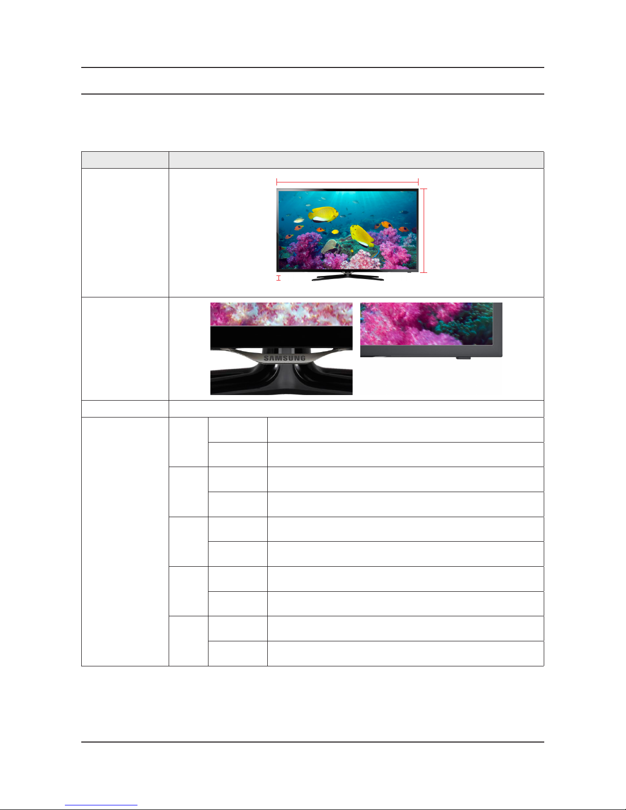
Model UE**F5500
Front View
W
* W : Width H : High D : Depth
H
D
Detail View
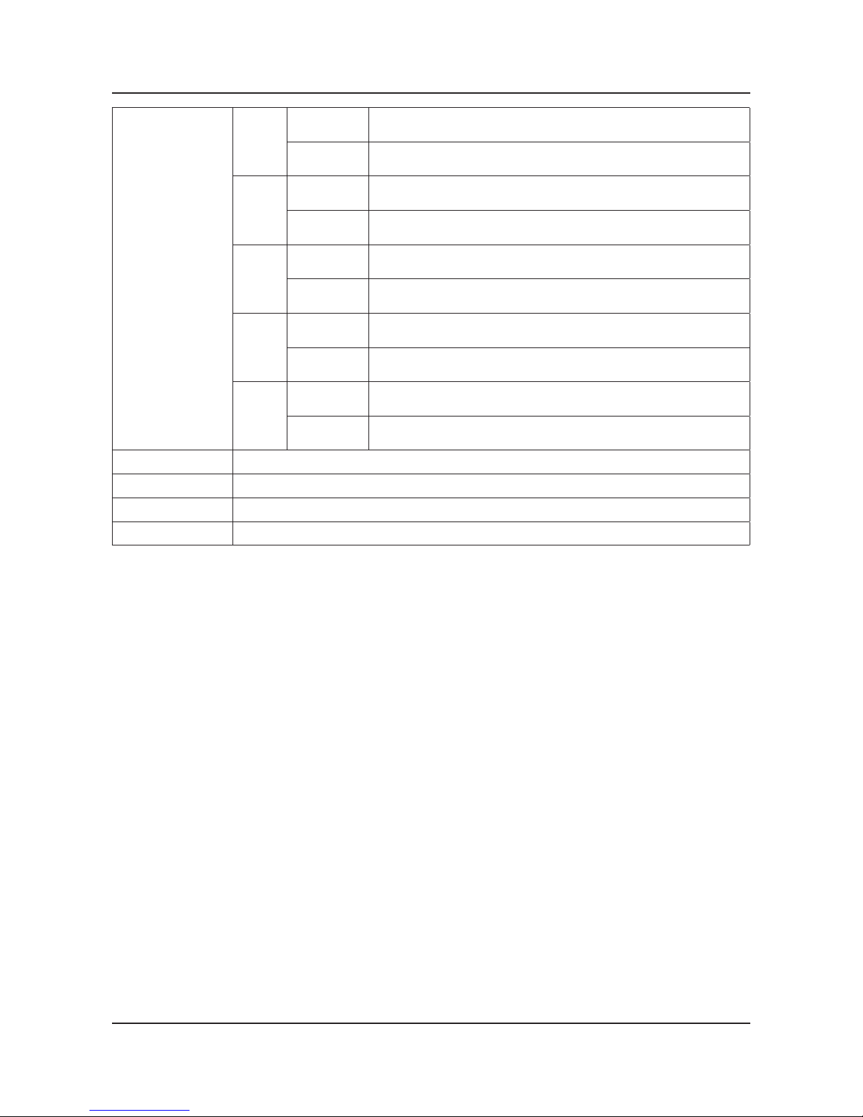
Front Color Black (Panel)
Dimensions
(W x H x D)
32F45
Set with
Stand
750.9 x 476.9 x 207.8 mm / 29.6 x 18.8 x 8.2 inches
Set without
Stand
750.9 x 456.6 x 59.3 mm / 29.6 x 18.0 x 2.3 inches
32F53
32F55
Set with
Stand
738.0 x 509.6 x 265.0 mm / 29.1 x 20.1 x 10.4 inches
Set without
Stand
738.0 x 445.4 x 49.0 mm / 29.1 x 17.5 x 1.9 inches
40F53
40F55
Set with
Stand
928.2 x 615.5 x 265.0 mm / 36.5 x 24.2 x 10.4 inches
Set without
Stand
928.2 x 552.3 x 49.4 mm / 36.5 x 21.7 x 1.9 inches
46F53
46F55
Set with
Stand
1059.6 x 700.0 x 307.3 mm / 41.7 x 27.6 x 12.1 inches
Set without
Stand
1059.6 x 626.2 x 49.4 mm / 41.7 x 24.7 x 1.9 inches
50F55
Set with
Stand
1135.4 x 741.8 x 307.3 mm / 44.7 x 29.2 x 12.2 inches
Set without
Stand
1135.4 x 668.0 x 49.8 mm / 44.7 x 26.3 x 2.0 inches
2-2
2. Product specications
Weight
32F45
Set with
Stand
5.6 kg / 12.3 lbs
Set without
Stand
5.3 kg / 11.7 lbs
32F53
32F55
Set with
Stand
5.7 kg / 12.6 lbs
Set without
Stand
5.0 kg / 11.0 lbs
40F53
40F55
Set with
Stand
8.9 kg / 19.6 lbs
Set without
Stand
8.0 kg / 17.6 lbs
46F53
46F55
Set with
Stand
11.5 kg / 25.4 lbs
Set without
Stand
10.8 kg / 23.8 lbs
50F55
Set with
Stand
14.7 kg / 32.4 lbs
Set without
Stand
13.0 kg / 28.7 lbs
Panel Type Anti Glare
Internal Memory 4 GByte
DDR 1 GByte
Feature Smart TV
2-3
2. Product specications
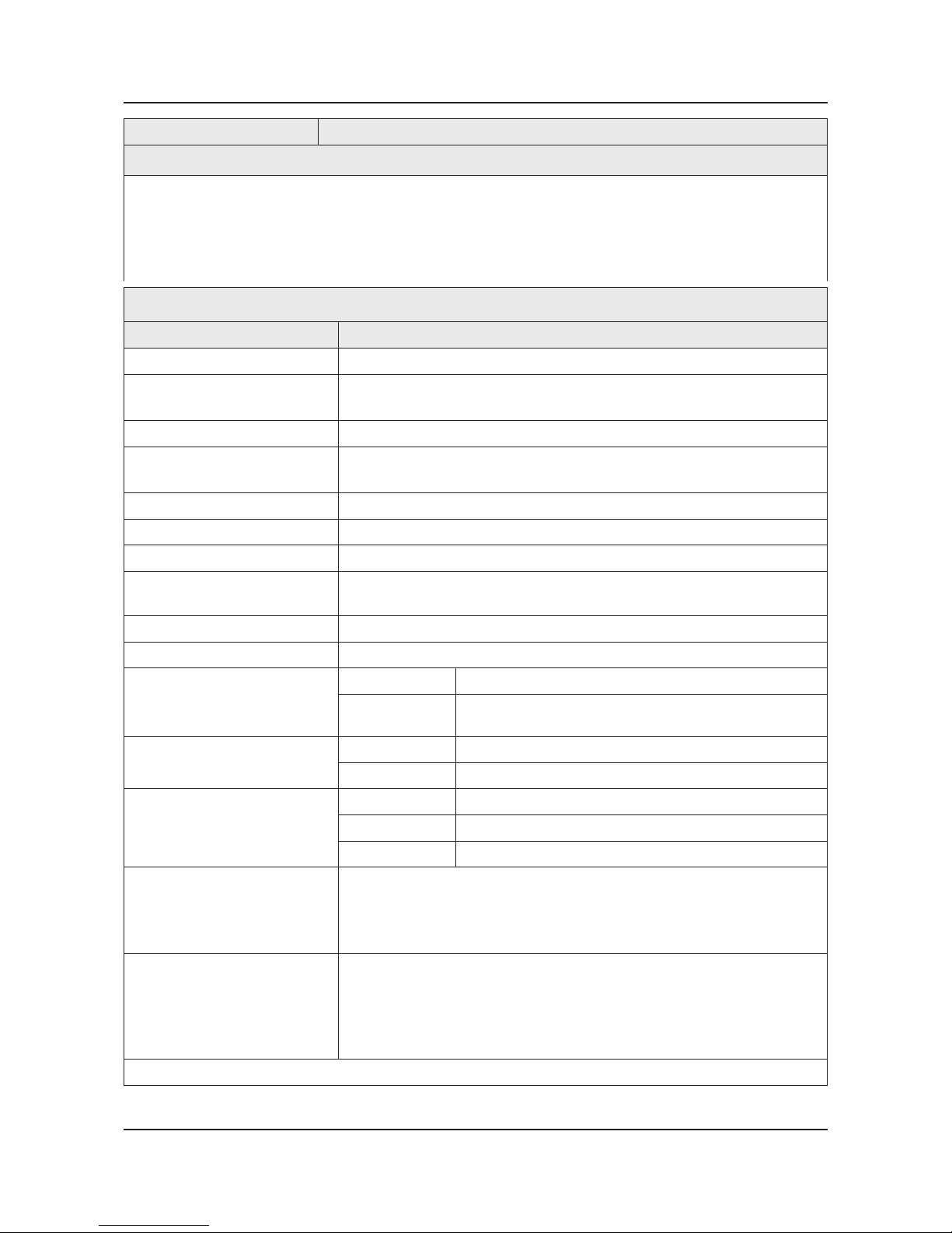
2-1-2. Feature & Specications
Model UA32F55**A* / UA32F5300A* (M or W: DVB-T, K: DVB-T2, R: READY)
Feature
Digital-TV, RF, 3-HDMI, 1-Component, 1-A/V, 2-USB2.0, LAN•
Brightness : 300 cd/m•
2
Dynamic Contrast Ratio : Mega Contrast•
Response Time : 6.5 ms•
CMR : 120•
Specications
Item Description
LCD Panel 32 inch FHD 60Hz
Scanning Frequency Horizontal : 60 kHz ~ 73 kHz (Automatic)
Vertical : 47 Hz ~ 63 Hz (Automatic)
Display Colors 16.7 M colors
Maximum Resolution Horizontal : 1920 Pixels
Vertical : 1080 Pixels
Input Signal Analog 0.7 Vp-p ± 5% positive at 75Ω, internally terminated
Input Sync Signal H/V Separate, TTL, P. or N.
Maximum Pixel Clock Rate 74.25 MHz
Active Display (H x V)*
* Horizontal x Vertical
698.4(H) X 392.9(V) (mm) / 27.5(H) X 15.5(V) (inches)
AC Power Voltage & Frequency AC 220 V ~ 240 V / AC 100 V ~ 240 V, 50 Hz / 60 Hz
Power Consumption 86 / 85 W (Under 0.3 W, Stand by)
Dimensions Set (W x H x D)*
* Width x High x Depth
Set with Stand 738.0 x 509.6 x 265.0 mm / 29.1 x 20.1 x 10.4 inches
Set without Stand 738.0 x 445.4 x 49.0 mm / 29.1 x 17.5 x 1.9 inches
Weight Set with Stand 5.7 kg / 12.6 lbs
Set without Stand 5.0 kg / 11.0 lbs
TV System Tuning Frequency Synthesize (Refer to detailed Frequency Table)
System DVB-T/C/T2C(depend on country), PAL , SECAM , NT4.43
Sound PAL-B/G/I/D/K, Nicam, Dolby Digital Plus/Pulse
Environmental Considerations Operating Temperature: 50˚F ~ 104˚F (10˚C ~ 40˚C)
Operating Humidity: 10% ~ 80%, non-condensing
Storage Temperature: -4˚F ~ 113˚F (-20˚C ~ 45˚C)
Storage Humidity: 5% ~ 95%, non-condensing
Audio Specications MAX Internal Audio Output Power : Each 10 W(Left/Right)
Equalizer : 5 Band
Output Frequency :
RF : 20 Hz ~ 15.4 kHz•
AV/Componet/HDMI : 20 Hz ~ 20 kHz•
Note : Dolby Digital Plus/Pulse, USB2.0, Film mode, Energy Saving, Eco sensor, SmartTV
2-4
2. Product specications
Model UA40F55**A* / UA40F53**A* (M or W: DVB-T, K: DVB-T2, R: READY)
Feature
Digital-TV, RF, 3-HDMI, 1-Component, 1-A/V, 2-USB2.0, LAN•
Brightness : 300 cd/m•
2
Dynamic Contrast Ratio : Mega Contrast•
Response Time : 6.5 ms•
CMR : 100•
Specications
Item Description
LCD Panel 40 inch FHD 60Hz
Scanning Frequency Horizontal : 60 kHz ~ 73 kHz (Automatic)
Vertical : 47 Hz ~ 63 Hz (Automatic)
Display Colors 16.7 M colors
Maximum Resolution Horizontal : 1920 Pixels
Vertical : 1080 Pixels
Input Signal Analog 0.7 Vp-p ± 5% positive at 75Ω, internally terminated
Input Sync Signal H/V Separate, TTL, P. or N.
Maximum Pixel Clock Rate 74.25 MHz
Active Display (H x V)*
* Horizontal x Vertical
885.6(H) X 498.2(V) (mm) / 34.9(H) X 19.6(V) (inches)
AC Power Voltage & Frequency AC 220 V ~ 240 V / AC 100 V ~ 240 V, 50 Hz / 60 Hz
Power Consumption 115 / 117 W (Under 0.3 W, Stand by)
Dimensions Set (W x H x D)*
* Width x High x Depth
Set with Stand 928.2 x 615.5 x 265.0 mm / 36.5 x 24.2 x 10.4 inches
Set without Stand 928.2 x 552.3 x 49.4 mm / 36.5 x 21.7 x 1.9 inches
Weight Set with Stand 8.9 kg / 19.6 lbs
Set without Stand 8.0 kg / 17.6 lbs
TV System Tuning Frequency Synthesize (Refer to detailed Frequency Table)
System DVB-T/C/T2C(depend on country), PAL , SECAM , NT4.43
Sound PAL-B/G/I/D/K, Nicam, Dolby Digital Plus/Pulse
Environmental Considerations Operating Temperature: 50˚F ~ 104˚F (10˚C ~ 40˚C)
Operating Humidity: 10% ~ 80%, non-condensing
Storage Temperature: -4˚F ~ 113˚F (-20˚C ~ 45˚C)
Storage Humidity: 5% ~ 95%, non-condensing
Audio Specications MAX Internal Audio Output Power : Each 10 W(Left/Right)
Equalizer : 5 Band
Output Frequency :
RF : 20 Hz ~ 15.4 kHz•
AV/Componet/HDMI : 20 Hz ~ 20 kHz•
Note : Dolby Digital Plus/Pulse, USB2.0, Film mode, Energy Saving, Eco sensor, SmartTV

2-5
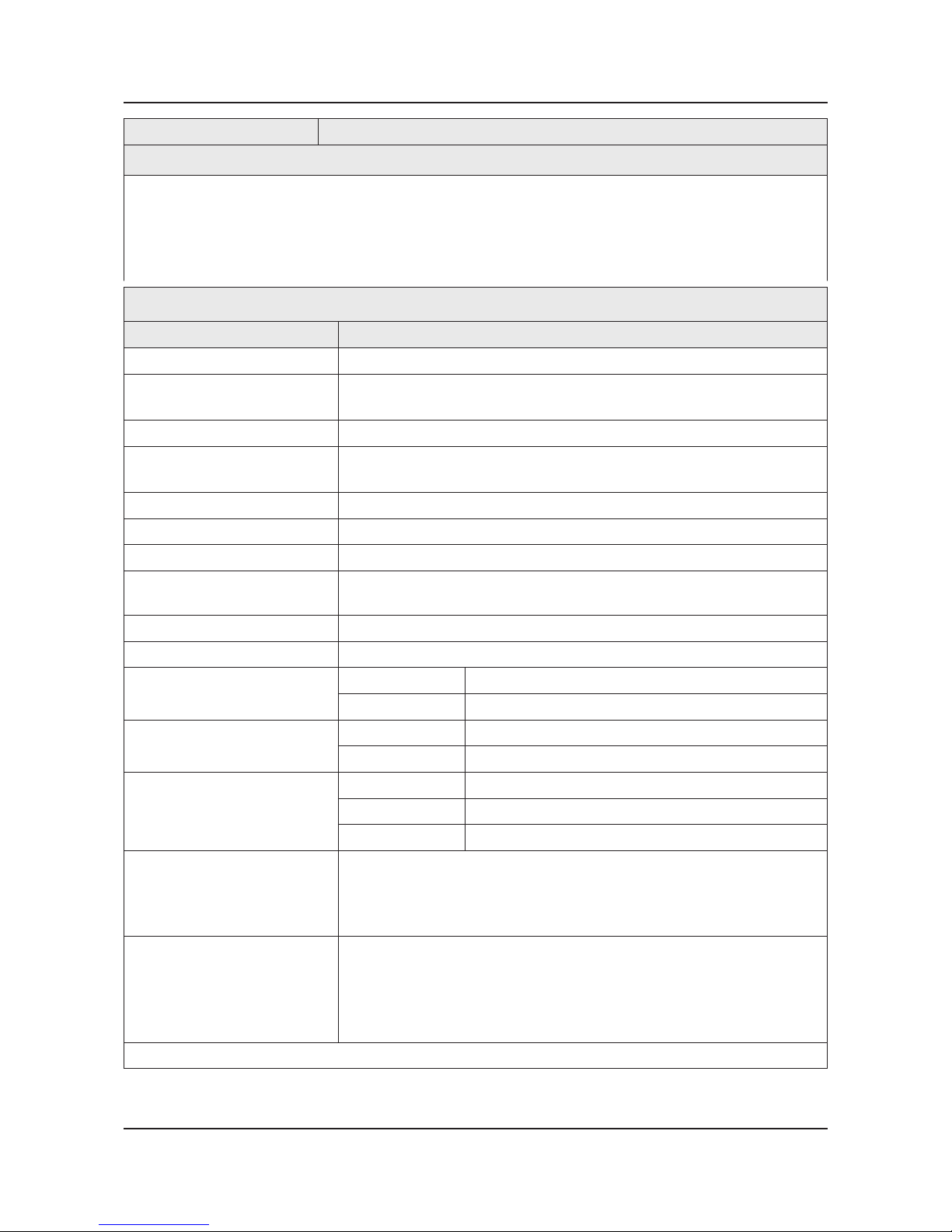
2. Product specications
Model UA46F55**A* / UA46F53**A* (M or W: DVB-T, K: DVB-T2, R: READY)
Feature
Digital-TV, RF, 3-HDMI, 1-Component, 1-A/V, 2-USB2.0, LAN•
Brightness : 300 cd/m•
2
Dynamic Contrast Ratio : Mega Contrast•
Response Time : 6.5 ms•
CMR : 100•
Specications
Item Description
LCD Panel 46 inch FHD 60Hz
Scanning Frequency Horizontal : 60 kHz ~ 73 kHz (Automatic)
Vertical : 47 Hz ~ 63 Hz (Automatic)
Display Colors 16.7 M colors
Maximum Resolution Horizontal : 1920 Pixels
Vertical : 1080 Pixels
Input Signal Analog 0.7 Vp-p ± 5% positive at 75Ω, internally terminated
Input Sync Signal H/V Separate, TTL, P. or N.
Maximum Pixel Clock Rate 74.25 MHz
Active Display (H x V)*
* Horizontal x Vertical
1018.1(H) X 572.7(V) (mm) / 40.1(H) X 22.5(V) (inches)
AC Power Voltage & Frequency AC 220 V ~ 240 V / AC 100 V ~ 240 V, 50 Hz / 60 Hz
Power Consumption 117 / 119 W (Under 0.3 W, Stand by)
Dimensions Set (W x H x D)*
* Width x High x Depth
Set with Stand 1059.6 x 700.0 x 307.3 mm / 41.7 x 27.6 x 12.1 inches
Set without Stand 1059.6 x 626.2 x 49.4 mm / 41.7 x 24.7 x 1.9 inches
Weight Set with Stand 11.5 kg / 25.4 lbs
Set without Stand 10.8 kg / 23.8 lbs
TV System Tuning Frequency Synthesize (Refer to detailed Frequency Table)
System DVB-T/C/T2C(depend on country), PAL , SECAM , NT4.43
Sound PAL-B/G/I/D/K, Nicam, Dolby Digital Plus/Pulse
Environmental Considerations Operating Temperature: 50˚F ~ 104˚F (10˚C ~ 40˚C)
Operating Humidity: 10% ~ 80%, non-condensing
Storage Temperature: -4˚F ~ 113˚F (-20˚C ~ 45˚C)
Storage Humidity: 5% ~ 95%, non-condensing
Audio Specications MAX Internal Audio Output Power : Each 10 W(Left/Right)
Equalizer : 5 Band
Output Frequency :
RF : 20 Hz ~ 15.4 kHz•
AV/Componet/HDMI : 20 Hz ~ 20 kHz•
Note : Dolby Digital Plus/Pulse, USB2.0, Film mode, Energy Saving, Eco sensor, SmartTV

2-6
2. Product specications
Model UA50F55**A* (M or W: DVB-T, K: DVB-T2, R: READY)
Feature
Digital-TV, RF, 3-HDMI, 1-Component, 1-A/V, 2-USB2.0, LAN•
Brightness : 300 cd/m•
2
Dynamic Contrast Ratio : Mega Contrast•
Response Time : 6.5 ms•
CMR : 100•
Specications
Item Description
LCD Panel 50 inch FHD 60Hz
Scanning Frequency Horizontal : 60 kHz ~ 73 kHz (Automatic)
Vertical : 47 Hz ~ 63 Hz (Automatic)
Display Colors 16.7 M colors
Maximum Resolution Horizontal : 1920 Pixels
Vertical : 1080 Pixels
Input Signal Analog 0.7 Vp-p ± 5% positive at 75Ω, internally terminated
Input Sync Signal H/V Separate, TTL, P. or N.
Maximum Pixel Clock Rate 74.25 MHz
Active Display (H x V)*
* Horizontal x Vertical
1023.0(H) X 577.6(V) (mm) / 40.3(H) X 22.7(V) (inches)
AC Power Voltage & Frequency AC 220 V ~ 240 V / AC 100 V ~ 240 V, 50 Hz / 60 Hz
Power Consumption 139 / 143 W (Under 0.3 W, Stand by)
Dimensions Set (W x H x D)*
* Width x High x Depth
Set with Stand 1135.4 x 741.8 x 307.3 mm / 44.7 x 29.2 x 12.2 inches
Set without Stand 1135.4 x 668.0 x 49.8 mm / 44.7 x 26.3 x 2.0 inches
Weight Set with Stand 14.7 kg / 32.4 lbs
Set without Stand 13.0 kg / 28.7 lbs
TV System Tuning Frequency Synthesize (Refer to detailed Frequency Table)
System DVB-T/C/T2C(depend on country), PAL , SECAM , NT4.43
Sound PAL-B/G/I/D/K, Nicam, Dolby Digital Plus/Pulse
Environmental Considerations Operating Temperature: 50˚F ~ 104˚F (10˚C ~ 40˚C)
Operating Humidity: 10% ~ 80%, non-condensing
Storage Temperature: -4˚F ~ 113˚F (-20˚C ~ 45˚C)
Storage Humidity: 5% ~ 95%, non-condensing
Audio Specications MAX Internal Audio Output Power : Each 10 W(Left/Right)
Equalizer : 5 Band
Output Frequency :
RF : 20 Hz ~ 15.4 kHz•
AV/Componet/HDMI : 20 Hz ~ 20 kHz•
Note : Dolby Digital Plus/Pulse, USB2.0, Film mode, Energy Saving, Eco sensor, SmartTV
2-7
2. Product specications
Model UA32F45**A* (M or W: DVB-T, K: DVB-T2, R: READY)
Feature
Digital-TV, RF, 3-HDMI, 1-Component, 1-A/V, 2-USB2.0, LAN•
Brightness : 300 cd/m•
2
Dynamic Contrast Ratio : Mega Contrast•
Response Time : 6.5 ms•
CMR : 120•
Specications
Item Description
LCD Panel 32 inch FHD 60Hz
Scanning Frequency Horizontal : 60 kHz ~ 73 kHz (Automatic)
Vertical : 47 Hz ~ 63 Hz (Automatic)
Display Colors 16.7 M colors
Maximum Resolution Horizontal : 1366 Pixels
Vertical : 768 Pixels
Input Signal Analog 0.7 Vp-p ± 5% positive at 75Ω, internally terminated
Input Sync Signal H/V Separate, TTL, P. or N.
Maximum Pixel Clock Rate 74.25 MHz
Active Display (H x V)*
* Horizontal x Vertical
703.4(H) X 397.8(V) (mm) / 27.7(H) X 15.7(V) (inches)
AC Power Voltage & Frequency AC 220 V ~ 240 V / AC 100 V ~ 240 V, 50 Hz / 60 Hz
Power Consumption 68 / 70 W (Under 0.3 W, Stand by)
Dimensions Set (W x H x D)*
* Width x High x Depth
Set with Stand 750.9 x 476.9 x 207.8 mm / 29.6 x 18.8 x 8.2 inches
Set without Stand 750.9 x 456.6 x 59.3 mm / 29.6 x 18.0 x 2.3 inches
Weight Set with Stand 5.6 kg / 12.3 lbs
Set without Stand 5.3 kg / 11.7 lbs
TV System Tuning Frequency Synthesize (Refer to detailed Frequency Table)
System DVB-T/C/T2C(depend on country), PAL , SECAM , NT4.43
Sound PAL-B/G/I/D/K, Nicam, Dolby Digital Plus/Pulse
Environmental Considerations Operating Temperature: 50˚F ~ 104˚F (10˚C ~ 40˚C)
Operating Humidity: 10% ~ 80%, non-condensing
Storage Temperature: -4˚F ~ 113˚F (-20˚C ~ 45˚C)
Storage Humidity: 5% ~ 95%, non-condensing
Audio Specications MAX Internal Audio Output Power : Each 10 W(Left/Right)
Equalizer : 5 Band
Output Frequency :
RF : 20 Hz ~ 15.4 kHz•
AV/Componet/HDMI : 20 Hz ~ 20 kHz•
Note : Dolby Digital Plus/Pulse, USB2.0, Film mode, Energy Saving, SmartTV
2-8
2. Product specications
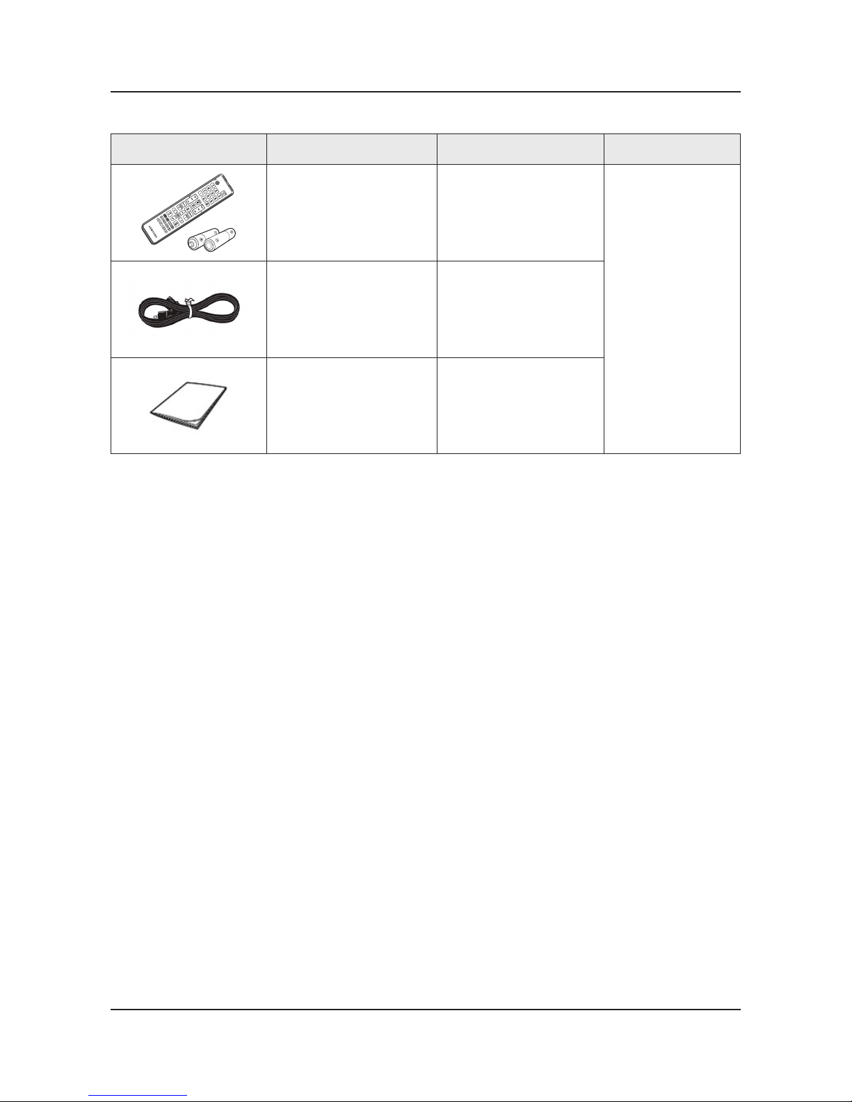
2-2. Accessories
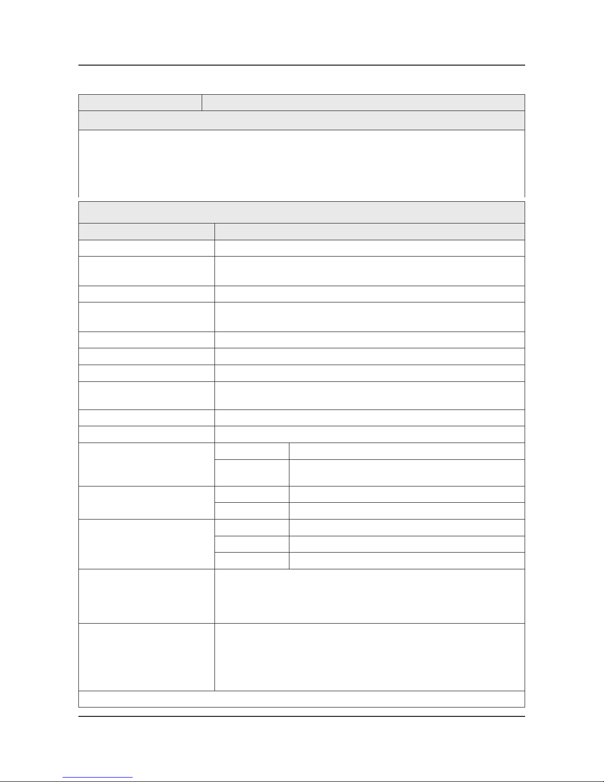
Product Description Code. No Remark
Remote Control & Batteries
(AAA x 2)
AA59-00790A (AU)
AA59-00793A (NZ,SG)
AA59-00797A (Etc.)
Power Cord
3903-000845 (AU,NZ)
3903-000847 (SG)
3903-000849 (Etc.)
Owners Manual
BN68-04827A (AU)
BN68-04827F (NZ)
BN68-04827C (SG)
BN68-04827B (Etc.)
3-1
3. Disassembly and Reassemble
3. Disassembly and Reassembly
This section of the service manual describes the disassembly and reassembly procedures for the LED TV.
WARNING
This LED TV contains electrostatically sensitive devices. Use caution when handling these components.
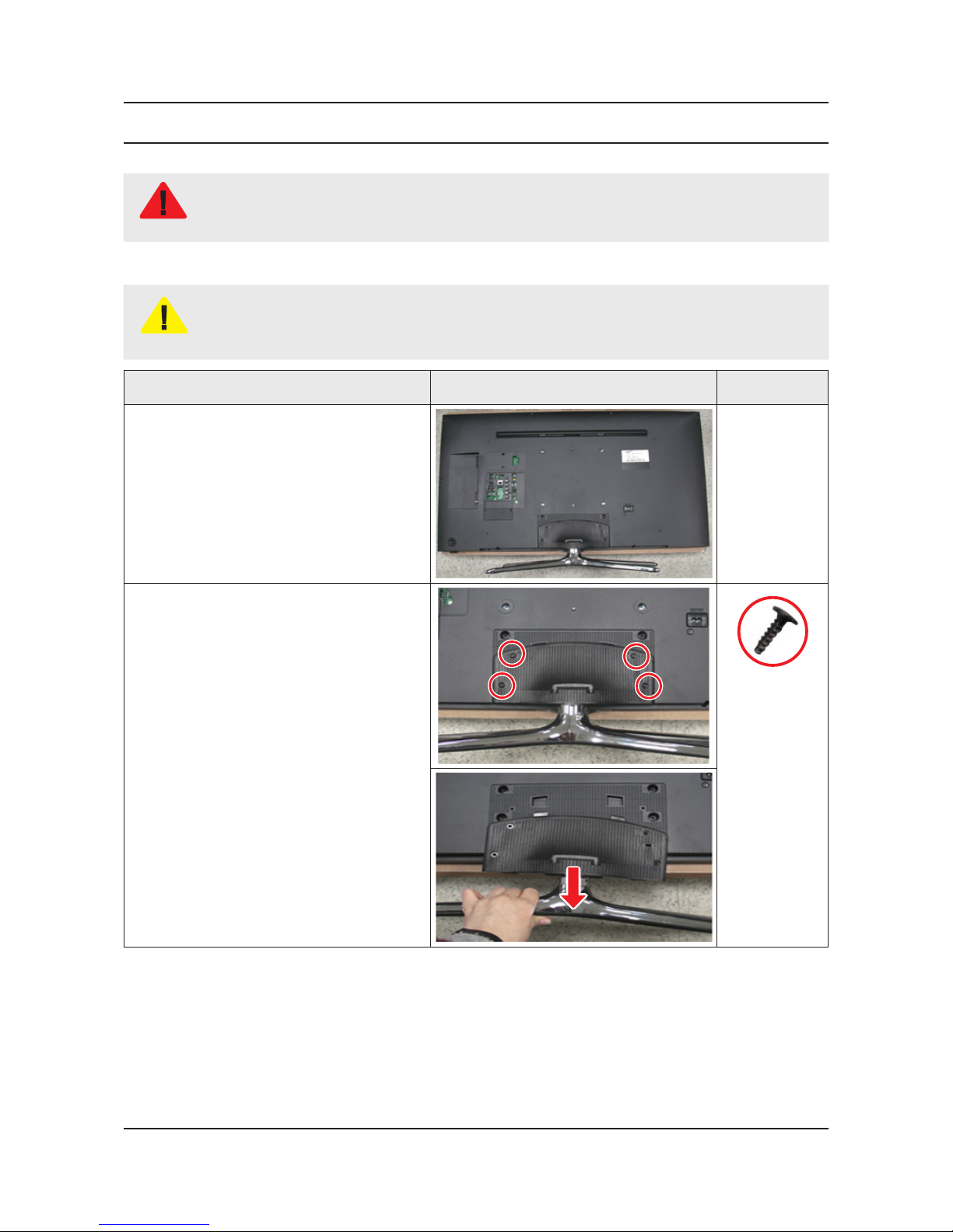
3-1. Disassembly and Reassembly
CAUTION
Disconnect the LED TV from the power source before disassembly.1.
Follow these directions carefully; never use metal instruments to pry apart the cabinet.2.
If there is no additional coment, it is same for all inches.3.
Description Picture Description Screws
1
Place TV face down on cushioned table.
2
Remove 4 screws from the Stand and
Remove Stand.
6003-001782
3-2
3. Disassembly and Reassemble
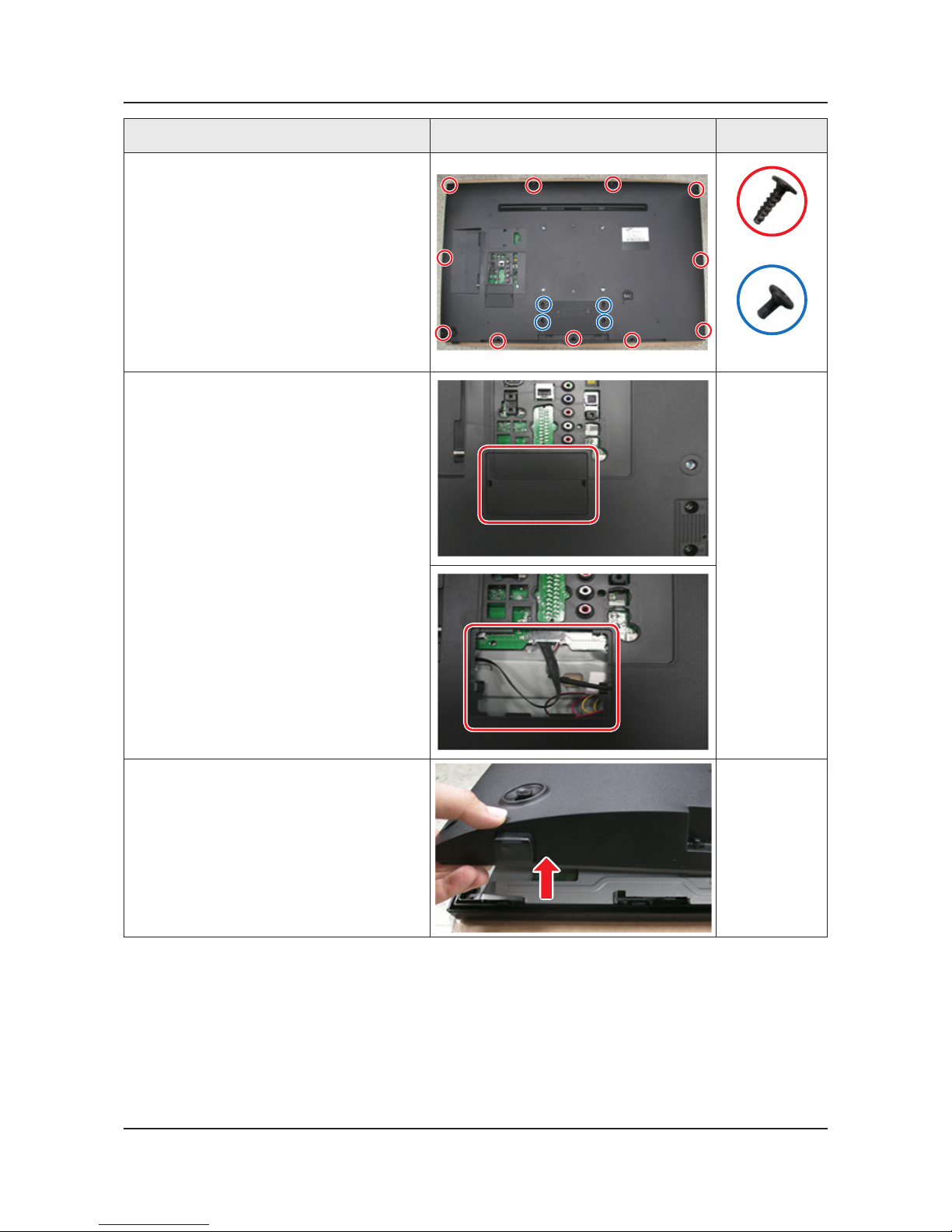
Description Picture Description Screws
3
Remove 15 screws of Rear Cover.
6003-001782
6003-002755
4
Remove the Cover Jack.
5
Lift up Rear Cover slightly from the bottom.
3-3
3. Disassembly and Reassemble
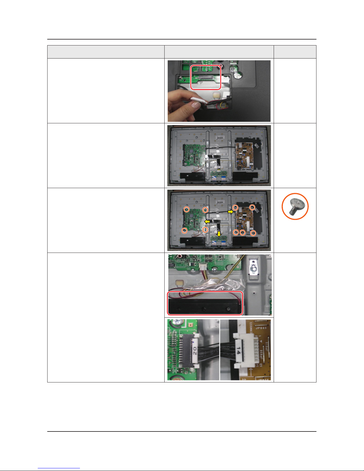
Description Picture Description Screws
6
Disconnect the Function Assy Cable.
7
Remove the Rear Cover.
8
Remove 9 screws of Main Board and
Power Board.
6001-003016
9
Remove the Speakers and Power Cables.
3-4
3. Disassembly and Reassemble
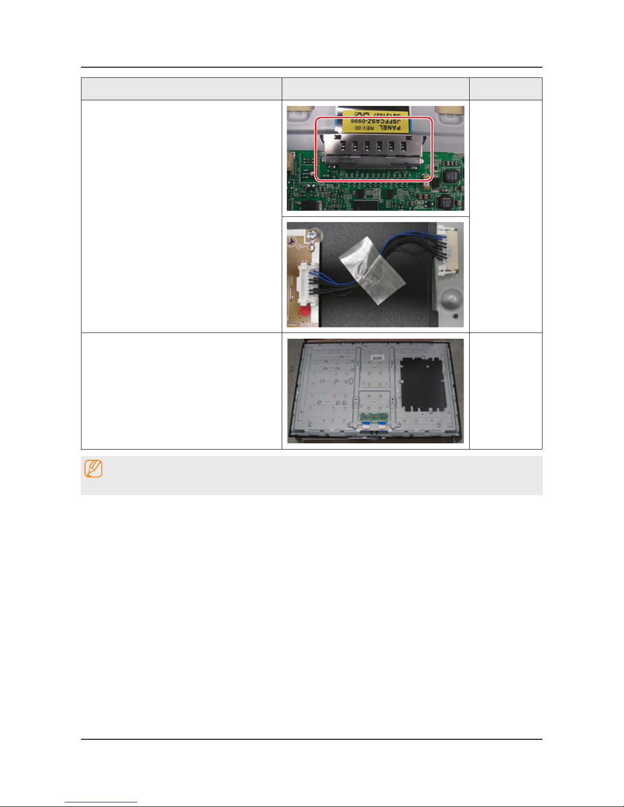
Description Picture Description Screws
10
Remove the LVDS Cable and Panel Drive
Cable.
11
Completed disassembly.
NOTE
Reassembly procedures are in the reverse order of disassembly procedures.
3-5
3. Disassembly and Reassemble
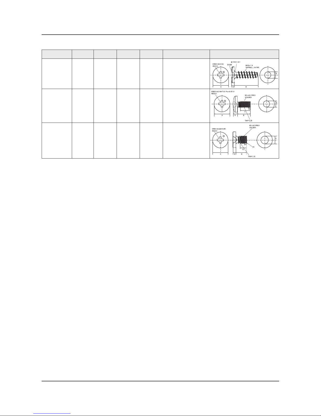
Screw Size
Code No. COLOR A (mm) B (mm) C (mm) Q'ty Screw Image
6003-001782 BLACK 7.80~8.20 1.85~1.95 3.81~3.91
32" : 10EA,
40" : 17EA,
46": 20EA,
50" : 20EA
A
CROSS #2(3.56)
RECESS
B 8.0R
★ C 0.6 ± 0.1
M4.0 x 1.8
TAPPING △ B-TYPE
BD
C
6001-002755 BLACK 7.1~7.5 1.9~2.0 2.98~3.02
32" : 2EA,
40"/46"/50": 4EA
A
CROSS #2(3.08 특수 Punch D:7.5
RECESS
M3 x 0.5 PITCH
SCALOCK
TRAP 도포
인치
BD
E
C
6001-003016 WHITE 5.6~6.0 1.15~1.25 2.92~2.98 9EA
A
CROSS #2(★M3.0F)
RECESS
M3 x 0.5 PITCH
SCALOCK
B
B
D
C
TRAP 도포
인치
3-6
3. Disassembly and Reassemble
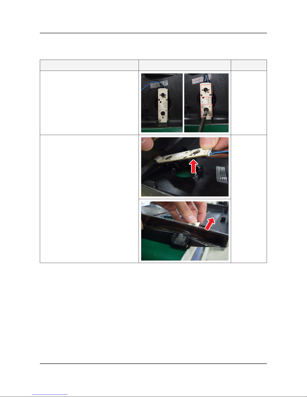
3-2. Assy Board P-Jog Switch & Ir
How to disassembly
Description Picture Description Refer
1
Loosen 2 screws.
2
Pull out a jog function.
3-7
3. Disassembly and Reassemble
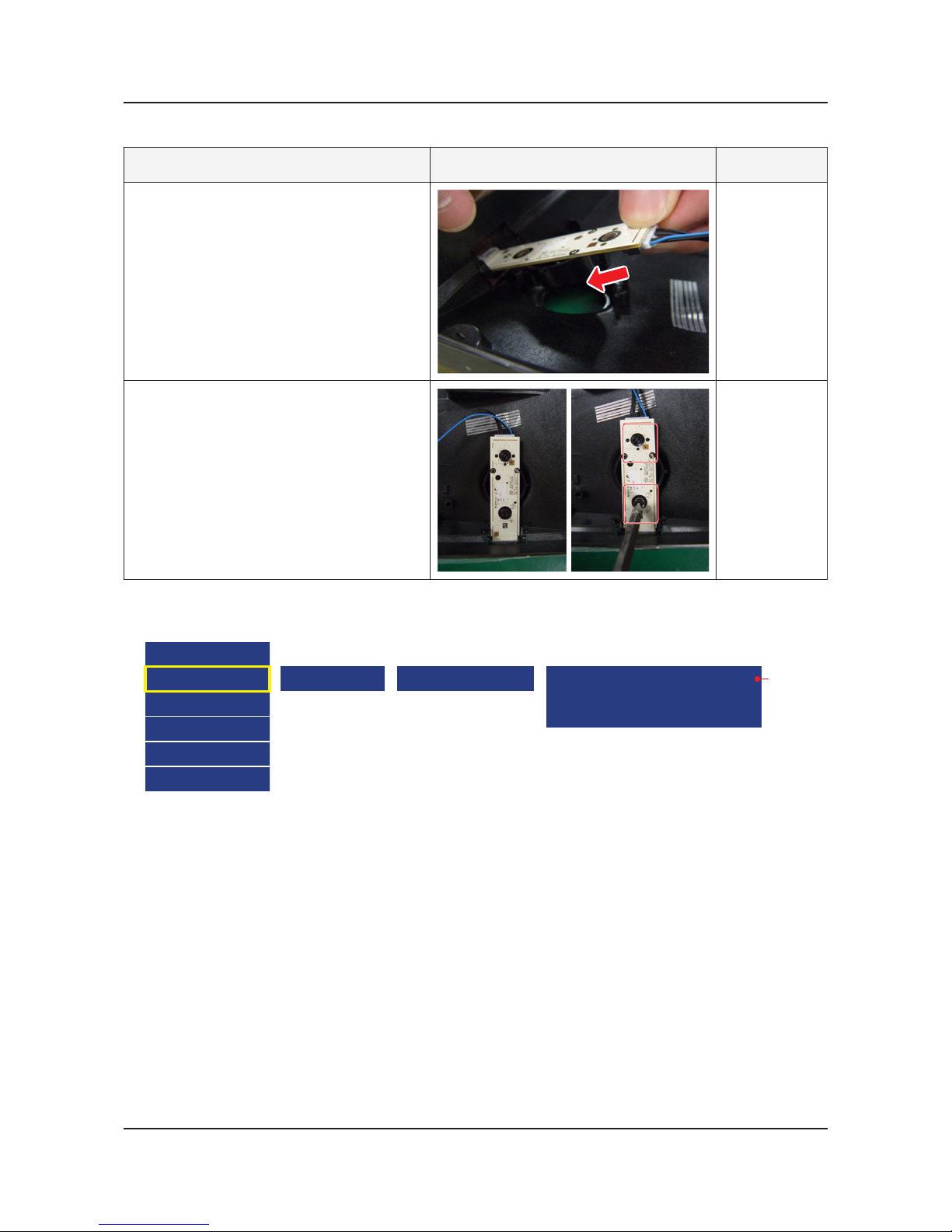
How to assembly
Description Picture Description Refer
1
Insert a jog function.
2
Put 2 screws.
When you want to ignore the funtion key actions
Option
Control
Debug
SVC
ADC/WB
Advanced
Cong Option Navigation Key Func
0 : New Function (Naviagtion) Key
1 : Old Function (Touch) Key
2 : Do not work Function key
[ Default ]
3-8
3. Disassembly and Reassemble
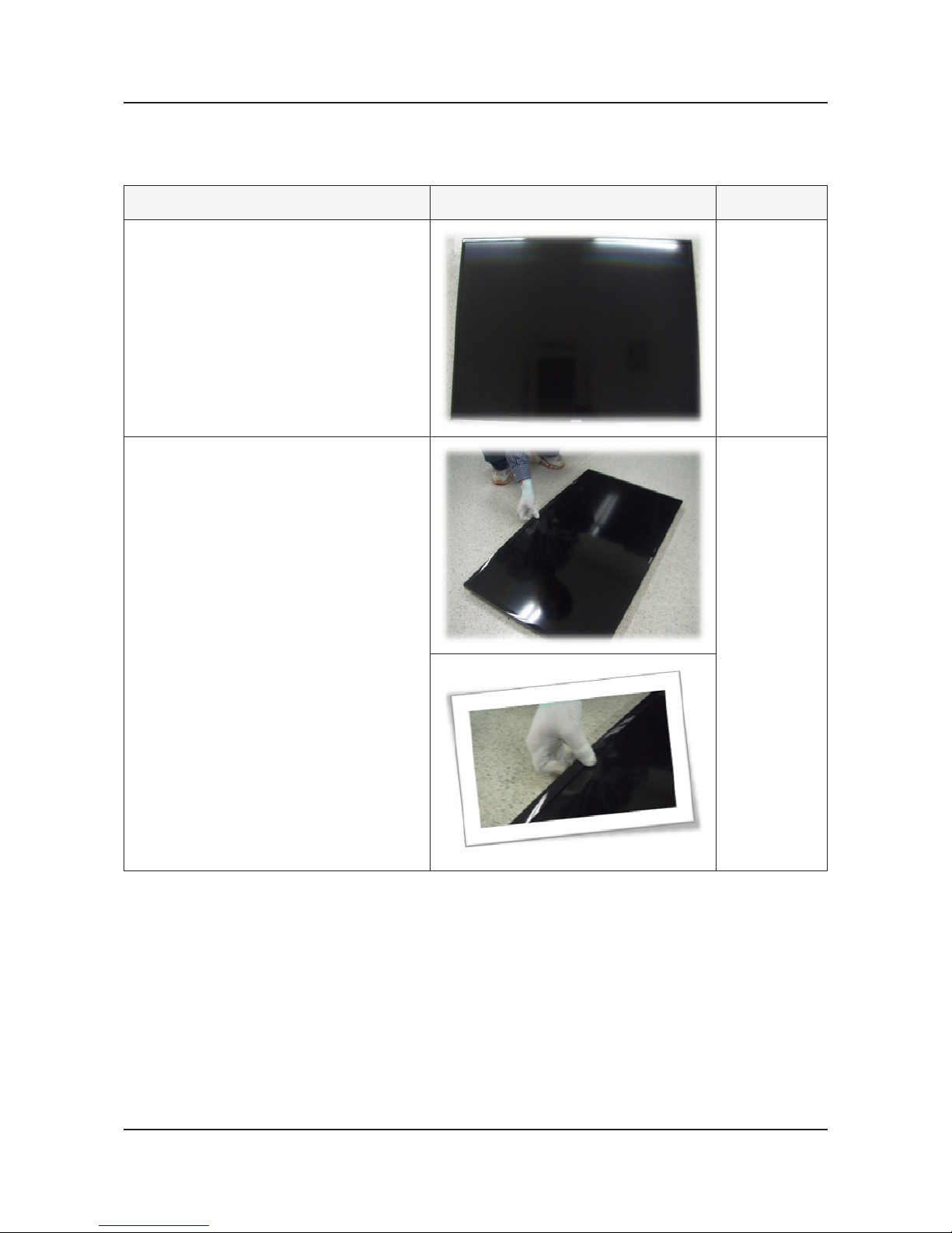
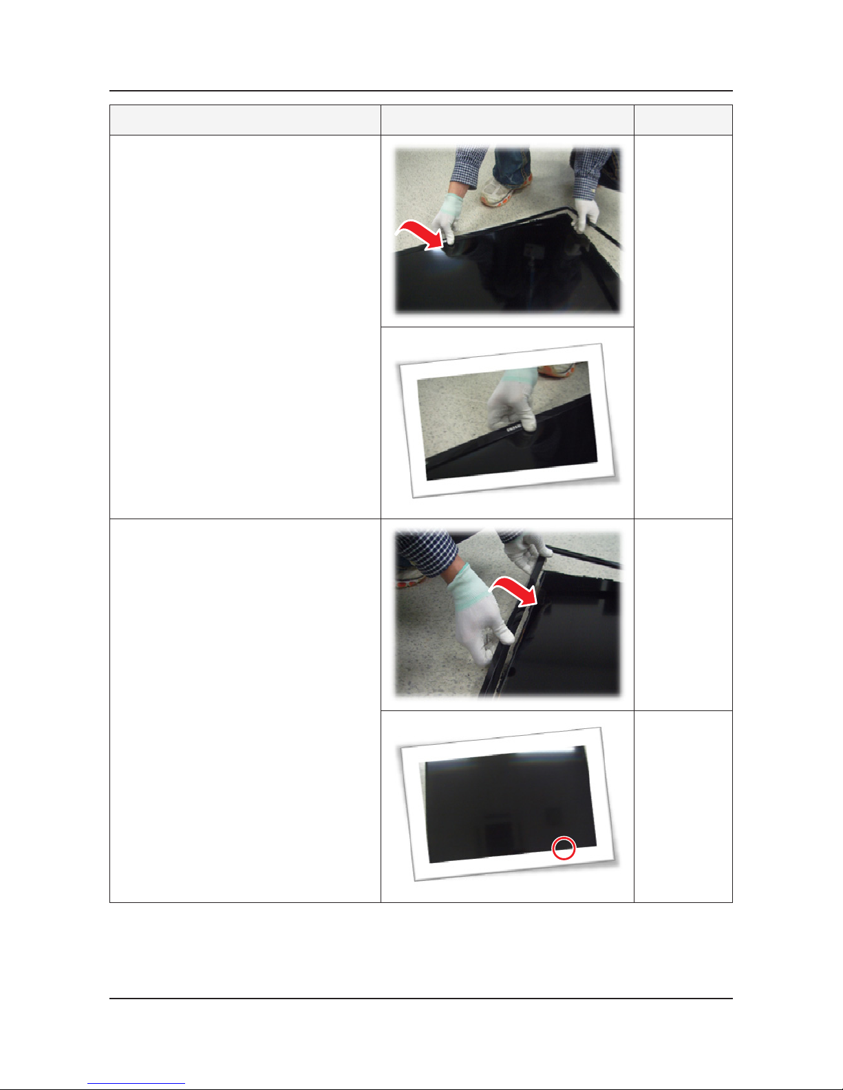
3-3. Disassembly(PTC)
How to disassembly
Description Picture Description Refer
1
Place TV face up on cushioned table.
2
Products at the top of the central TOPCHASSIS is rotated by 45 degrees outward
and pulls.
3-9
3. Disassembly and Reassemble
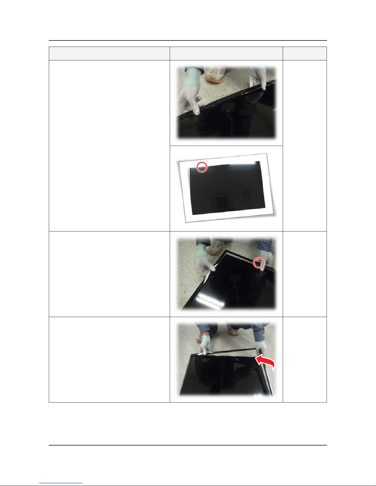
Description Picture Description Refer
3
Pull in the same way from the center of the
top.
4
Pull the left part of the product as shown
while holding the raised portion on gure 3.
5
Pull the bottom part of the product as
gure 2 while holding the raised portion on
gure 4.
3-10
3. Disassembly and Reassemble
Description Picture Description Refer
6
As shown in the picture, Lift the bottom of
the TOP-CHASSIS.
7
Pull the products at the bottom of the right
side of the chassis.
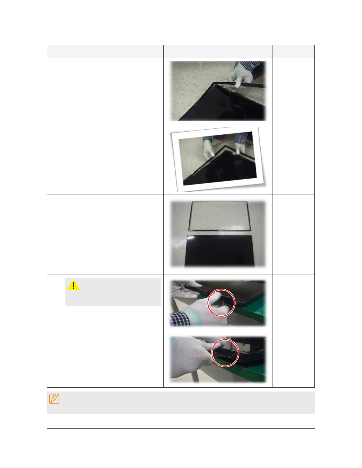
3-11
3. Disassembly and Reassemble
Description Picture Description Refer
8
Lift the bottom of the chassis with one
hand and holding the bottom of the product
after you pull the right side of the product
chassis.
9
Disassembly is complete.
CAUTION
To use JIG : Does not lift the chassis by
hand, JIG using the lift.
NOTE
Reassembly procedures are in the reverse order of disassembly procedures.
4. Troubleshooting
4-1. Troubleshooting
Previous Check
Check the various cable connections rst.1.
Check to see if there is a burnt or damaged cable. -
Check to see if there is a disconnected or loose cable connection. -
Check to see if the cables are connected according to the connection diagram. -
Check the power input to the Main Board.2.
How to distinguish if the problem is caused by Main Board or T-Con Board.3.
No Video - : If the problem is No Video but BLU is on and Indication LED is blinking repeatedly and faster than
nomal booting, replace the T-Con Board.
Distorted Picture - : Check the inner patterns.
For All mode
X12 FOX_FT1 FRC Post Picture Problem
OK OK NG Main Board or Signal Source
NG OK NG Main Board
NG NG NG Main or LVDS cable or T-con or Panel
Only for HDMI mode (additional check)
HDMI Picture Problem
OK NG There is no problems after HDMI IC check HDMI source or HDMI jack.
NG NG There is no problems before HDMI IC check X10+ pattern or LVDS cable or T-con.
How to check inner pattern?
Factory mode. ((mute → 1 → 8 → 2 → Power on when TV is in ‘stand-by mode’)1.
Move to SVC menu.2.
Move to Test Pattern.3.
Check inner patterns.4.
4-1
4. Troubleshooting
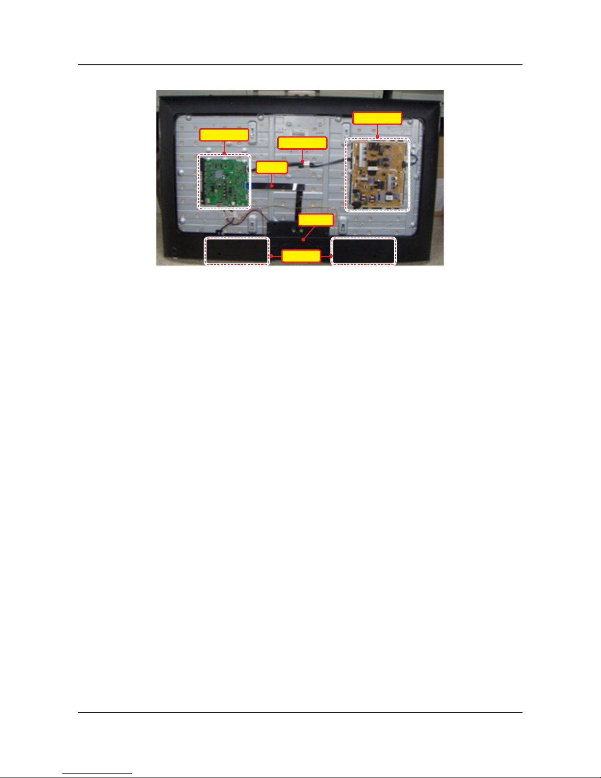
Inside View
Main Ass’y
20P Cable
LVDS
T-Con
Speaker
Power Ass’y
4-2
4. Troubleshooting
4-2. How to Check Fault Symptom
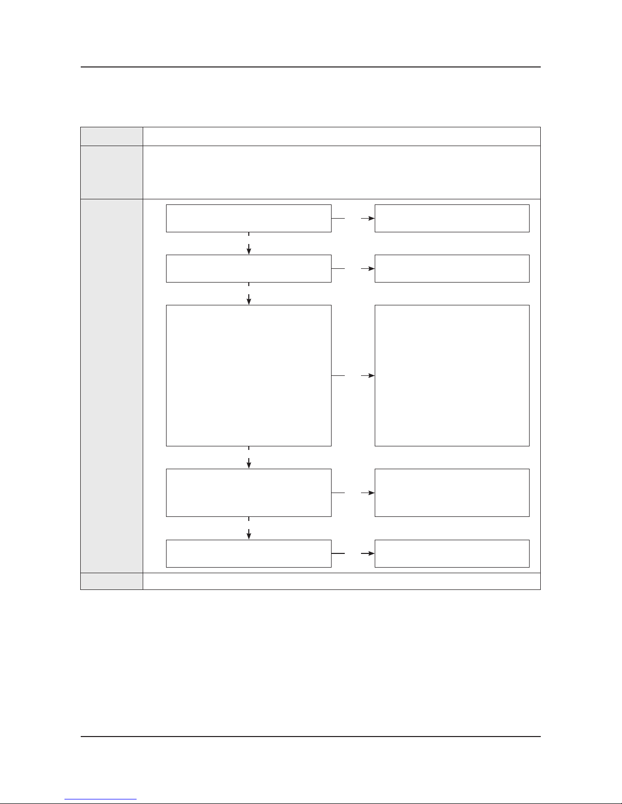
No Video (HDMI 1, 2, 3 - Digital Signal)
*Refer to the next page to check the lacation such a CN201 or IC201 SVC Manual mentioned.
Symptom
Audio is normal but no picture is displayed on the screen.•
Major
checkpoints
Check the HDMI source.•
Check the HDMI switch.•
This may happen when the LVDS cable connecting the Main Board and the Panel is •
disconnected.
Diagnostics
Power indicator LED is off.
Lamp(Backlight) on, no video ?
No
Check a set in the ‘Stand-by mode’.
Yes
Check the HDMI source and
check the connection of HDMI cable ?
No
Input the HDMI signal properly.
Yes
1
Check the signal at Input of Main board ?
HDMI1 Clk : Pin #10, #12 of CN602_H2
DATA : Pin #7, #9, #4, #6, #1, #3 of
CN602_H2
HDMI2 Clk : Pin #10, #12 of CN603_H3
DATA : Pin #7, #9, #4, #6, #1, #3 of
CN603_H3
HDMI3 Clk : Pin #10, #12 of CN604_H4
DATA : Pin #7, #9, #4, #6, #1, #3 of
CN604_H4
HDMI4 Clk : Pin #10, #12 of CN601_H1
DATA : Pin #7, #9, #4, #6, #1, #3 of
CN601_H1
No
Check CN601~4.
Check HDMI cable.
Change the Main Ass’y
or
Check IC1001(X12).
Change the Main Ass’y.
Yes
2
Check the LVDS clk signal at output of
Main board.(TX)
TX2_CLK : ODD_TXCLK_DN/DP
TX4_CLK : EVEN_TXCLK_DN/DP
No
Check IC1001(X12).
Change the Main Ass’y.
Yes
Check the LVDS cable?
Replace the T-con / LCD panel?
No
Please, Contact Tech support.
Caution Make sure to disconnect the power before working on the IP board.
4-3
4. Troubleshooting
 Loading...