

Samsung SCP-3430(P) User Manual

Smart Dome Camera
User Manual
SCP-3430(P)
2_ overview
overview
CAUTION
RISK OF ELECTRIC SHOCK.
DO NOT OPEN
CAUTION:
TO REDUCE THE RISK OF ELECTRIC SHOCK, DO NOT REMOVE COVER (OR
BACK) NO USER SERVICEABLE PARTS INSIDE. REFER SERVICING TO QUALIFIED
SERVICE PERSONNEL.
This symbol indicates that dangerous voltage consisting a risk of
electric shock is present within this unit.
This symbol indicates that there are important operating and
maintenance instructions in the literature accompanying this unit.
WARNING
To reduce the risk of fire or electric shock, do not expose this appliance to rain or
moisture.
To prevent injury, this apparatus must be securely attached to the floor/wall in
accordance with the installation instructions.
Use only the 24V, 60Hz AC adaptor for power supply.
WARNING
Be sure to use only the standard adapter that is specified in the specification sheet.
Using any other adapter could cause fire, electrical shock, or damage to the
product.
Incorrectly connecting the power supply or replacing battery may cause explosion,
fire, electric shock, or damage to the product.
Do not connect multiple cameras to a single adapter. Exceeding the capacity may
cause abnormal heat generation or fire.
Securely plug the power cord into the power receptacle. Insecure connection may
cause fire.
1.
2.
3.
4.

English _3
● OVERVIEW
When installing the camera, fasten it securely and firmly. The fall of camera may
cause personal injury.
Do not place conductive objects (e.g. screwdrivers, coins, metal parts, etc.) or
containers filled with water on top of the camera. Doing so may cause personal
injury due to fire, electric shock, or falling objects.
Do not install the unit in humid, dusty, or sooty locations. Doing so may cause fire
or electric shock.
If any unusual smells or smoke come from the unit, stop using the product. In such
case, immediately disconnect the power source and contact the service center.
Continued use in such a condition may cause fire or electric shock.
If this product fails to operate normally, contact the nearest service center. Never
disassemble or modify this product in any way. (SAMSUNG is not liable for
problems caused by unauthorized modifications or attempted repair.)
When cleaning, do not spray water directly onto parts of the product. Doing so may
cause fire or electric shock
Do not expose the product to the direct airflow from an air conditioner.
Otherwise, it may cause moisture condensation inside the Clear Dome due to
temperature difference between internal and external of the dome camera.
If you install this product in a low-temp area such as inside a cold store, you must
seal up the wiring pipe with silicon, so that the external air can not flow inside the
housing.
Otherwise, external high, humid air may flow inside the housing, pooling moisture
or vapor inside the product due to a difference between internal and external
temperature.
5.
6.
7.
8.
9.
10.
11.
12.

overview
4_ overview
CAUTION
Do not drop objects on the product or apply strong blows to it. Keep away from a
location subject to excessive vibration or magnetic interference.
Do not install in a location subject to high temperature (over 50°C), low temperature
(below -10°F), or high humidity. Doing so may cause fire or electric shock.
If you want to relocate the already installed product, be sure to turn off the power
and then move or reinstall it.
Remove the power plug from the outlet when there is a lighting storm. Neglecting
to do so may cause fire or damage to the product.
Keep out of direct sunlight and heat radiation sources. It may cause fire.
Install it in a place with good ventilation.
Avoid aiming the camera directly towards extremely bright objects such as sun, as
this may damage the CCD image sensor.
Apparatus shall not be exposed to dripping or splashing and no objects filled with
liquids, such as vases, shall be placed on the apparatus.
The Mains plug is used as a disconnect device and shall stay readily operable at
any time.
When using the camera outdoors, moisture may occur inside the camera due
to temperature difference between indoors and outdoors. For this reason, it is
recommended to install the camera indoors. For outdoor use, use the camera with
built-in fan and heater.
1.
2.
3.
4.
5.
6.
7.
8.
9.
10.
English _5
● OVERVIEW
FCC STATEMENT
This device complies with part 15 of the FCC Rules. Operation is subject to the following
two conditions :
1) This device may not cause harmful interference, and
2) This device must accept any interference received including interference that may
cause undesired operation.
CAUTION
This equipment has been tested and found to comply with the limits for a Class A
digital device, pursuant to part 15 of FCC Rules. These limits are designed to provide
reasonable protection against harmful interference when the equipment is operated
in a commercial environment.
This equipment generates, uses, and can radiate radio frequency energy and, if not
installed and used in accordance with the instruction manual, may cause harmful
interference to radio communications. Operation of this equipment in a residential
area is likely to cause harmful interference in which case the user will be required to
correct the interference at his own expense.
IC Compliance Notice
This Class A digital apparatus meets all requirements of the Canadian
Interference.-Causing Equipment Regulations of ICES-003.
overview
6_ overview
IMPORTANT SAFETY INSTRUCTIONS
Read these instructions.
Keep these instructions.
Heed all warnings.
Follow all instructions.
Do not use this apparatus near water.
Clean only with dry cloth.
Do not block any ventilation openings. Install in accordance with the manufacturer’s
instructions.
Do not install near any heat sources such as radiators, heat registers, or other
apparatus (including amplifiers) that produce heat.
Do not defeat the safety purpose of the polarized or grounding-type plug.
A polarized plug has two blades with one wider than the other. A grounding type
plug has two blades and a third grounding prong. The wide blade or the third prong
is provided for your safety. If the provided plug does not fit into your outlet, consult
an electrician for replacement of the obsolete outlet.
Protect the power cord from being walked on or pinched particularly at plugs,
convenience receptacles, and the point where they exit from the apparatus.
Only use attachments/accessories specified by the manufacturer.
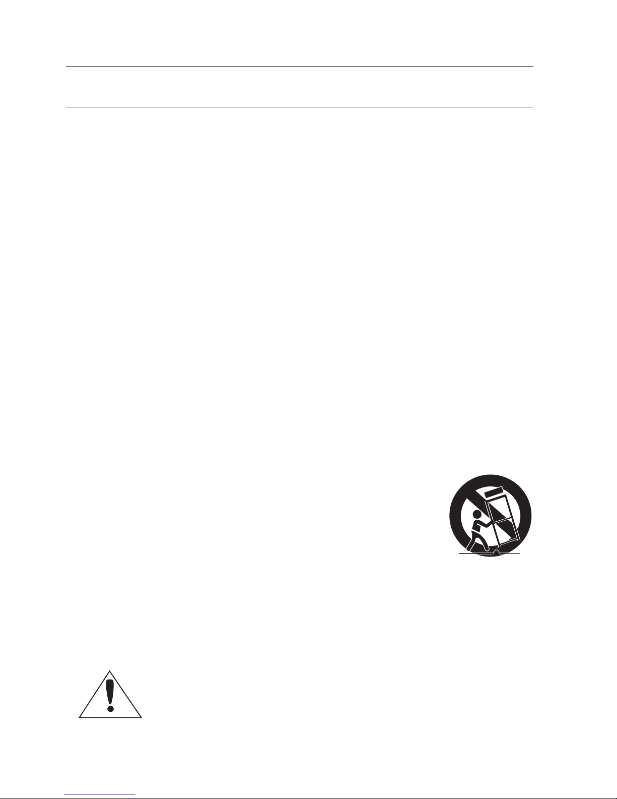
Use only with the cart, stand, tripod, bracket, or table specified
by the manufacturer, or sold with the apparatus. When a
cart is used, use caution when moving the cart/apparatus
combination to avoid injury from tip-over.
Unplug this apparatus during lightning storms or when unused
for long periods of time.
Refer all servicing to qualified service personnel. Servicing is required when the
apparatus has been damaged in any way, such as powersupply cord or plug is
damaged, liquid has been spilled or objects have fallen into the apparatus, the
apparatus has been exposed to rain or moisture, does not operate normally, or has
been dropped.
Apparatus shall not be exposed to dripping or splashing and no objects
filled with liquids, such as vases, shall be placed on the apparatus
1.
2.
3.
4.
5.
6.
7.
8.
9.
10.
11.
12.
13.
14.

English _7
● OVERVIEW
CONTENTS
OVERVIEW
2
6 Important Safety Instructions
7 Contents
8 Features
8 What’s Included
9 At a Glance
INSTALLATION &
CONN
ECTION
10
10 Preparing Installation
10 Installation
14 Initial Setup
17 Connecting with Other Device
SETUP
20
20 How to use the Keyboard
Controller
21 Main Menu
22 Profile
24 Camera Set
33 Intelligent Video
35 Privacy Zone
36 Preset
38 Auto Set
42 Zone Set
43 Alarm Set
45 Clock Set
45 Other Set
47 Communication
48 System Info
APPENDIX
49
49 Shortcut Keys
50 Specifications
52 Product Appearance
overview
8_ overview
FEATURES
With the state-of-the-art digital signal processing technology, full digital image
processing and special algorithm of 600-line high resolution implemented
High performance surveillance camera, equipped with x43 zoom lens and digital
zoom IC, enabling monitoring up to 688 times
WDR to cover the full screen irregardless of its brightness
DAY/NIGHT to improve the sensitivity by automatic conversion into the black and
white mode at night or in the environment with low illumination
White Balance to control the brightness to the illumination
Backlight Compensation under spotlight or utmost bright illumination
Auto Focus to automatically adjust the focus to the subject movement
Privacy zone to hide a specific area for personal privacy
PAN/TILT for precise control at high speed
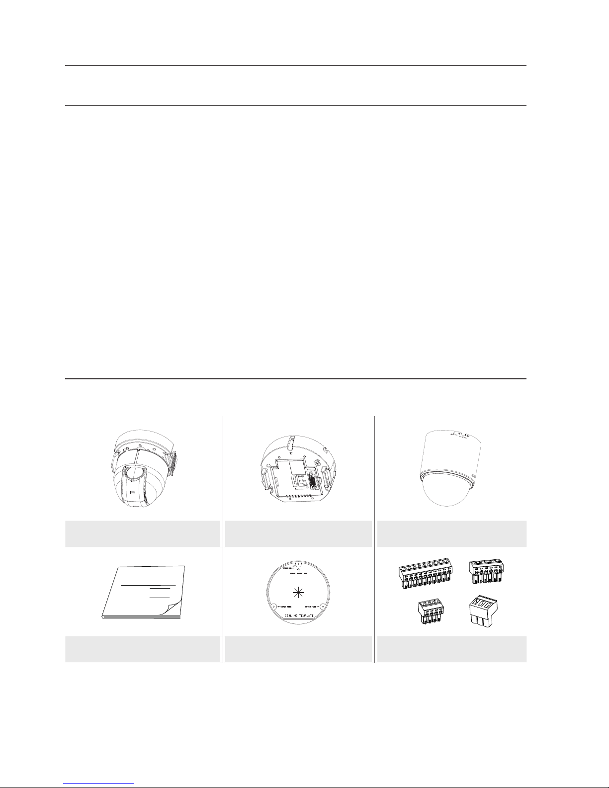
WHAT’S INCLUDED
Please check if your camera and accessories are all included in the product package.
SW602
SW602
SW602
Camera Frame Set Cover
User Manual
User Manual Template Connectors
English _9
● OVERVIEW
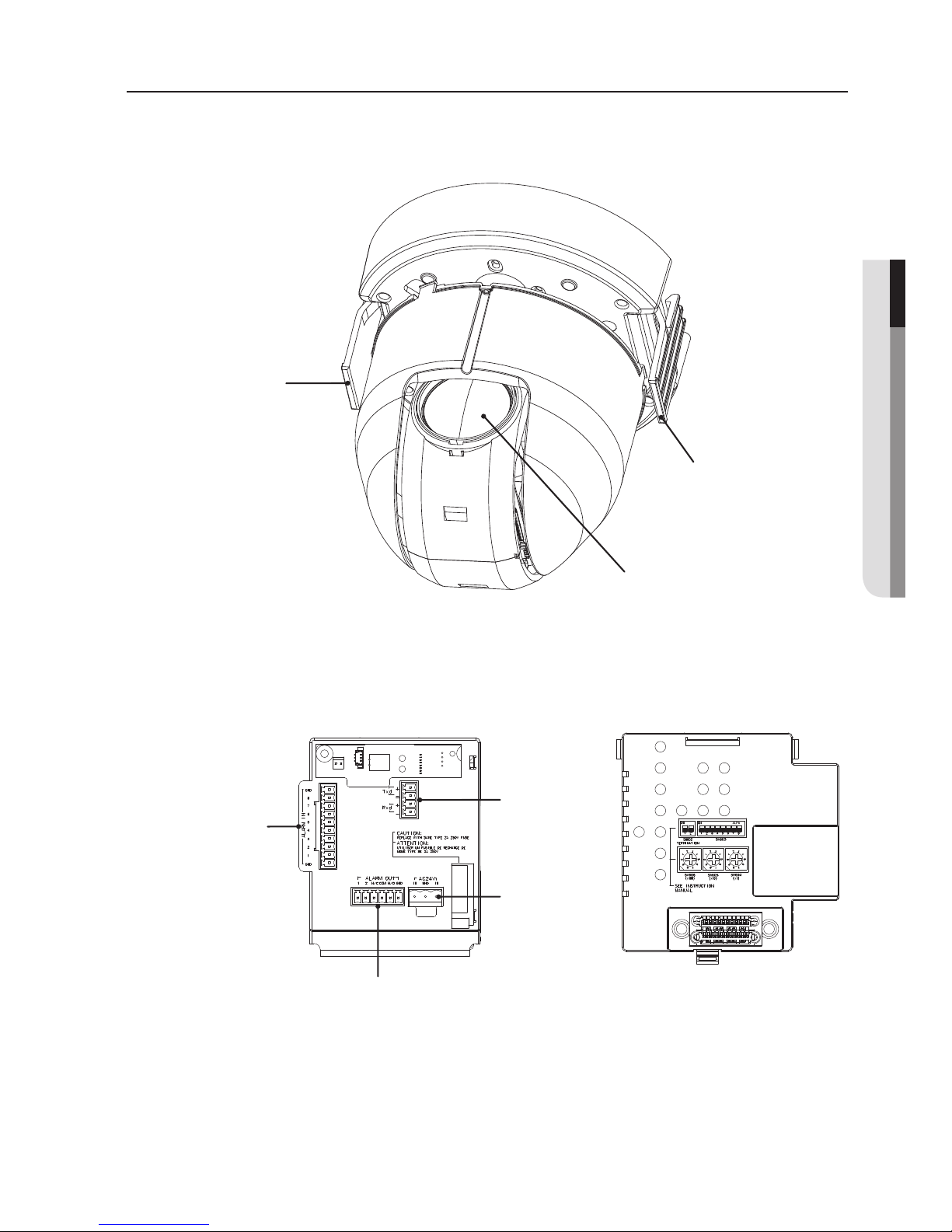
AT A GLANCE
CAMERA
FRAME SET
Wipe out a dirty surface of the lens softly with a lens tissue or cloth to which you
have applied ethanol.
M
LENS
HOOK
HOOK
ALARM IN
ALARM OUT
RS-485
POWER
INPUT
10_ installation & connection
installation & connection
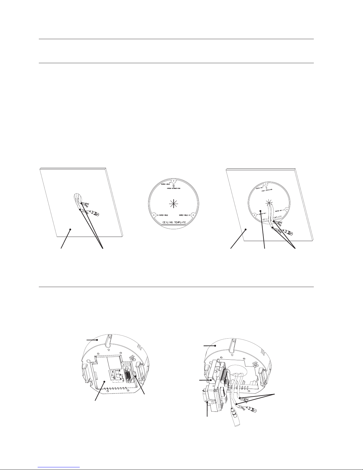
PREPARING INSTALLATION
Use the ceiling installation template when you install the camera on the ceiling on
your own.
Run the cables through the “” shaped hole on the center of the template, and
remove films on the adhesives, and then attach the template on the desired location
on the ceiling.
When installing the frames set, align all template’s screw holes and those of the
frames set.
This template prevents dust entering from the ceiling into the camera assembly.
INSTALLATION
Press the “SNAP FIT” on the “ADAPTOR” to open the “ADAPTOR”, and arrange
cables so they pass out of the “FRAME SET”.
1.
EXTERNAL
CABLES
FRAME SET
FRAME SET
ADAPTOR
SNAP FIT
ADAPTOR
SNAP FIT
<TEMPLATE>
CABLESCEILING CABLESCEILING TEMPLATE
English _11
● INSTALLATION & CONNECTION
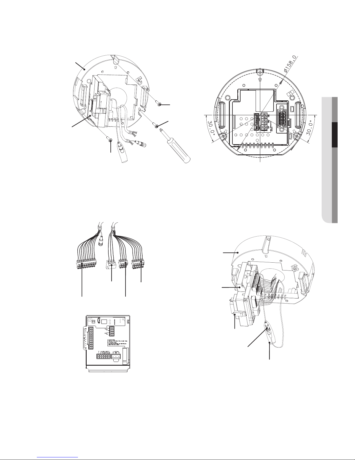
Use the three “SCREWS” to fix the “FRAME SET” on a “CAMERA” installation
position.
Connect external cables to the “CONNECTORS(ALARM IN, POWER, RS-485,
ALARM OUT)”and connect the “CONNECTOR” to the “ADAPTOR”.
Insert the cable into the “FRAME SET”, and close the “ADAPTOR”.
Then, wrap the “BNC JACK” with the “INSULATION TUBE”, and use an insulation
tape to seal up the end of the “INSULATION TUBE” so that the “BNC JACK” does
not protrude outside of the “INSULATION TUBE” coating.
For more information about cable connection, refer to “Connecting the adaptor
cable”. (page 19)
2.
3.
M
FRAME SET
ADAPTOR
SNAP FIT
INSULATION TUBE
BNC JACK
ALARM OUT
ALARM IN
RS-485
POWER INPUT
FRAME SET
ADAPTOR
SCREW
SCREW
SCREW
<Fixing Hole Diagram>
installation & connection
12_ installation & connection
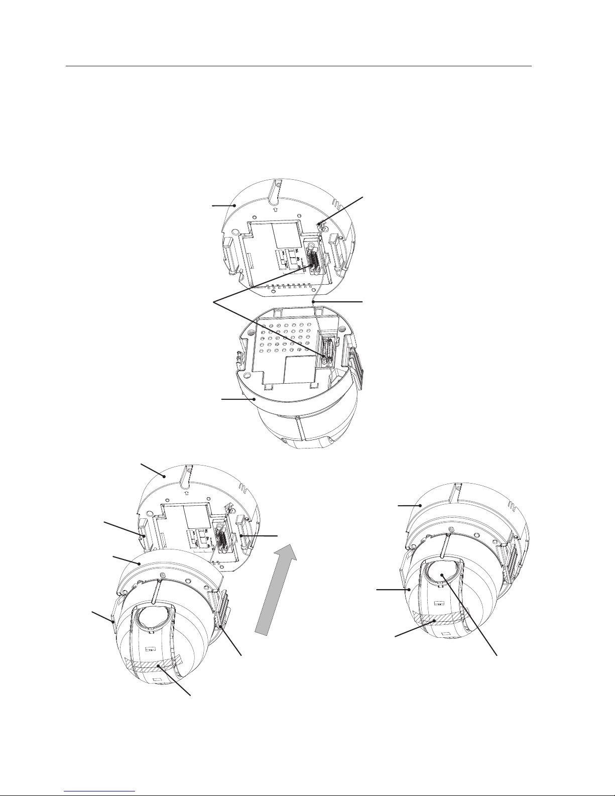
Connect the “SAFETY WIRE” of the “CAMERA” to the “BRACKET WIRE” on the
“FRAME SET”. Arrange the “22P CONNECTOR” of the “CAMERA” in line with that
of the “ADAPTOR”, push the “HOOK” on either end of the “CAMERA” in the “RACK”
direction of the “FRAME SET” to secure the two.
Then, ensure that all of the two “HOOKS” “clicks” to fix to the “RACK” properly.
When the installation is completed, remove the “PROTECTIVE FILM” and
“PROTECTIVE TAPE” from on the lens.
4.
M
FRAME SET
22P CONNECTOR
CAMERA
SAFETY WIRE
BRACKET WIRE
FRAME SET
CAMERA
RACK
HOOK
RACK
HOOK
CAMERA
FRAME SET
PROTECTIVE FILM
PROTECTIVE TAPE
PROTECTIVE TAPE

English _13
● INSTALLATION & CONNECTION
Arrange the “COVER” arrow in line with the “FRAME SET” arrow, and push in the
“COVER”. Insert the “COVER” to the end, and turn the “COVER” clockwise.
As shown in the figure below, turn it until you see the “BUTTON” hole and hear a
click.
Ensure that the “COVER” should not move any further if you turn the “COVER” counter
clockwise.
If you want to remove the “COVER”, hold down the “BUTTON” and turn the
“COVER” counter clockwise to remove the “COVER”.
5.
FRAME SET
BUTTON
CAMERA
COVER
COVER
BUTTON
COVER
installation & connection
14_ installation & connection
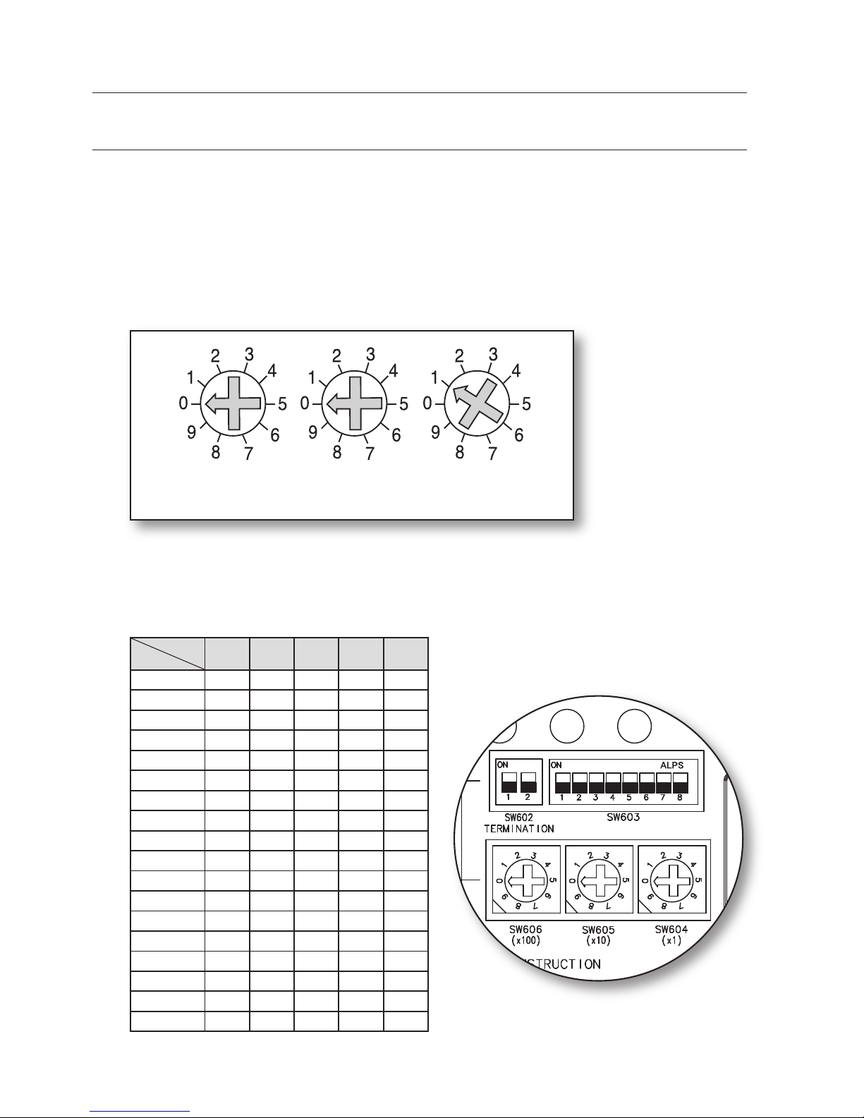
INITIAL SETUP
Camera Address Setup
Use SW606, SW605, and SW604 to specify the camera address.
You can specify between 0 and 255 for the address, where the hundreds digit is
with SW606, the tens digit with SW605, and the ones digit with SW604.
ex) Camera address: If the address is 1, follow the steps in the figure below.
Communication Protocol Setup
Use pins #1~#4 of SW603 to specify the communication protocol.
PIN
Comp
PIN1 PIN2 PIN3 PIN4 PIN7
A OFF OFF OFF OFF OFF
B ON OFF OFF OFF OFF
C OFF ON OFF OFF OFF
D ON ON OFF OFF OFF
E OFF OFF ON OFF OFF
--- ON OFF ON OFF OFF
--- OFF ON ON OFF OFF
H ON ON ON OFF OFF
I OFF OFF OFF ON OFF
J ON OFF OFF ON OFF
--- OFF ON OFF ON OFF
--- ON ON OFF ON OFF
--- OFF OFF ON ON OFF
N ON OFF ON ON OFF
O OFF ON ON ON OFF
P ON ON ON ON OFF
Q OFF OFF OFF OFF ON
R ON OFF OFF OFF ON
A : SAMSUNG HALF
B : SAMSUNG FULL
<Bottom of the camera holder>
SW606
(x100)
SW605
(x10)
SW604
(x1)
English _15
● INSTALLATION & CONNECTION
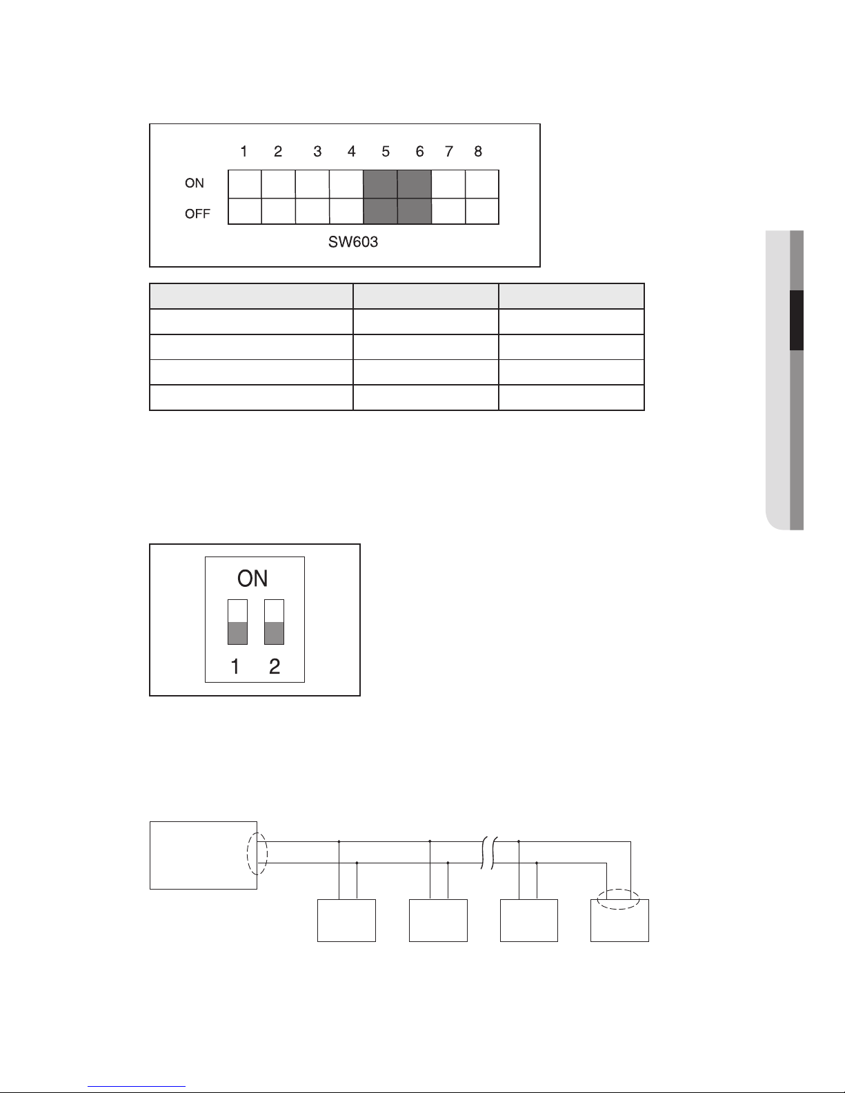
Baud Rate Setup
Use pins #5, #6 of SW603 to set the baud rate.
BAUD RATE PIN 5 PIN 6
4800 BPS ON ON
9600 BPS OFF ON
19200 BPS ON OFF
38400 BPS OFF OFF
The factory default is 9600 BPS.
Setting RS-422A/RS-485 Termination
As it is shown in the structure map, when Controller and RS-422A/RS-485 is
connected, it should be terminated according to the Cable feature of impedance
on the each end of the transmitting line to transfer the signals in long distance by
controlling the reflection of the signals to the lowest.
Termination : Using numbers 1 and 2 PIN, turn to <ON> and it will be terminated.
Controller
Termination
n < 32
Termination
SW1-ON
CAM n
CAM n-1
CAM 2
CAM 1
TX+(DATA+)
TX-(DATA-)
RX-
RX+
RX+ RX- RX+ RX- RX+ RX-
<RS-485 Half Duplex Organization>
installation & connection
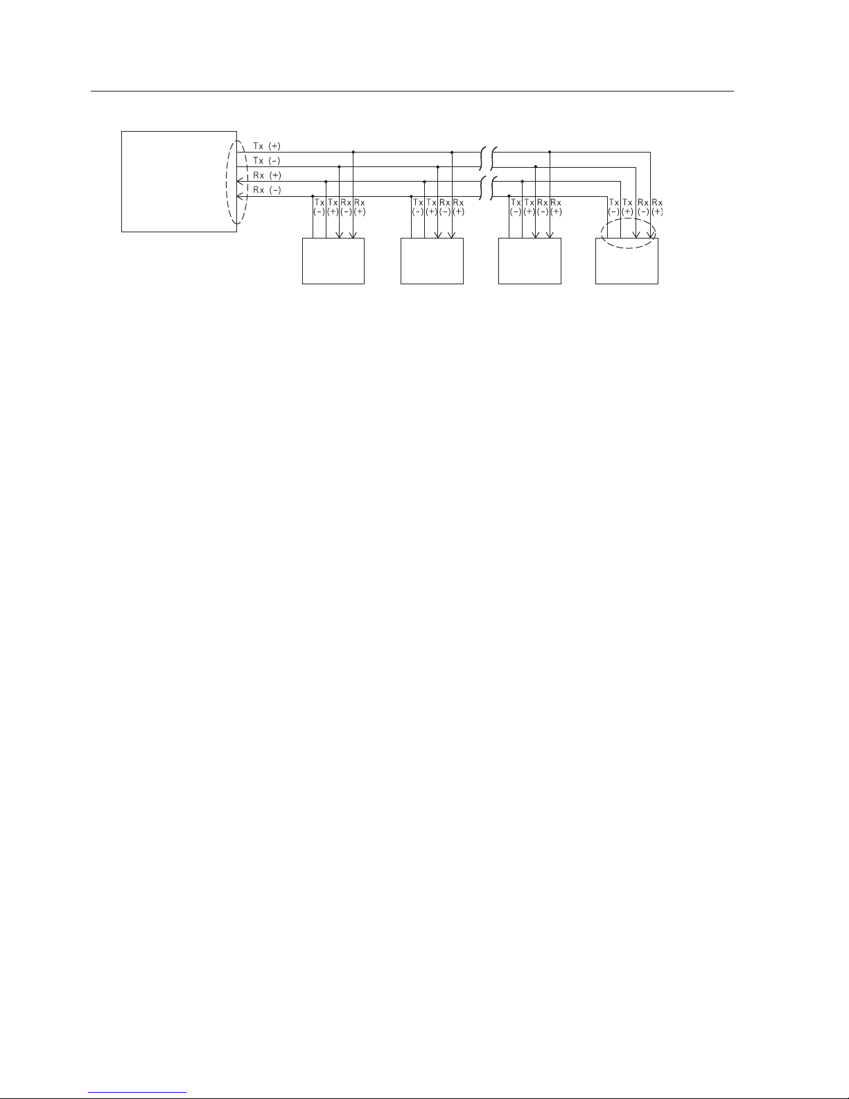
16_ installation & connection
A communication error may occur if you connect multiple cameras that are assigned
the same address in the network.
M
Controller
Termination
n < 32
Termination
SW1-ON
SW2-ON
CAM n
CAM n-1
CAM 2CAM 1
<RS-422A/RS-485 Full Duplex Organization>
English _17
● INSTALLATION & CONNECTION
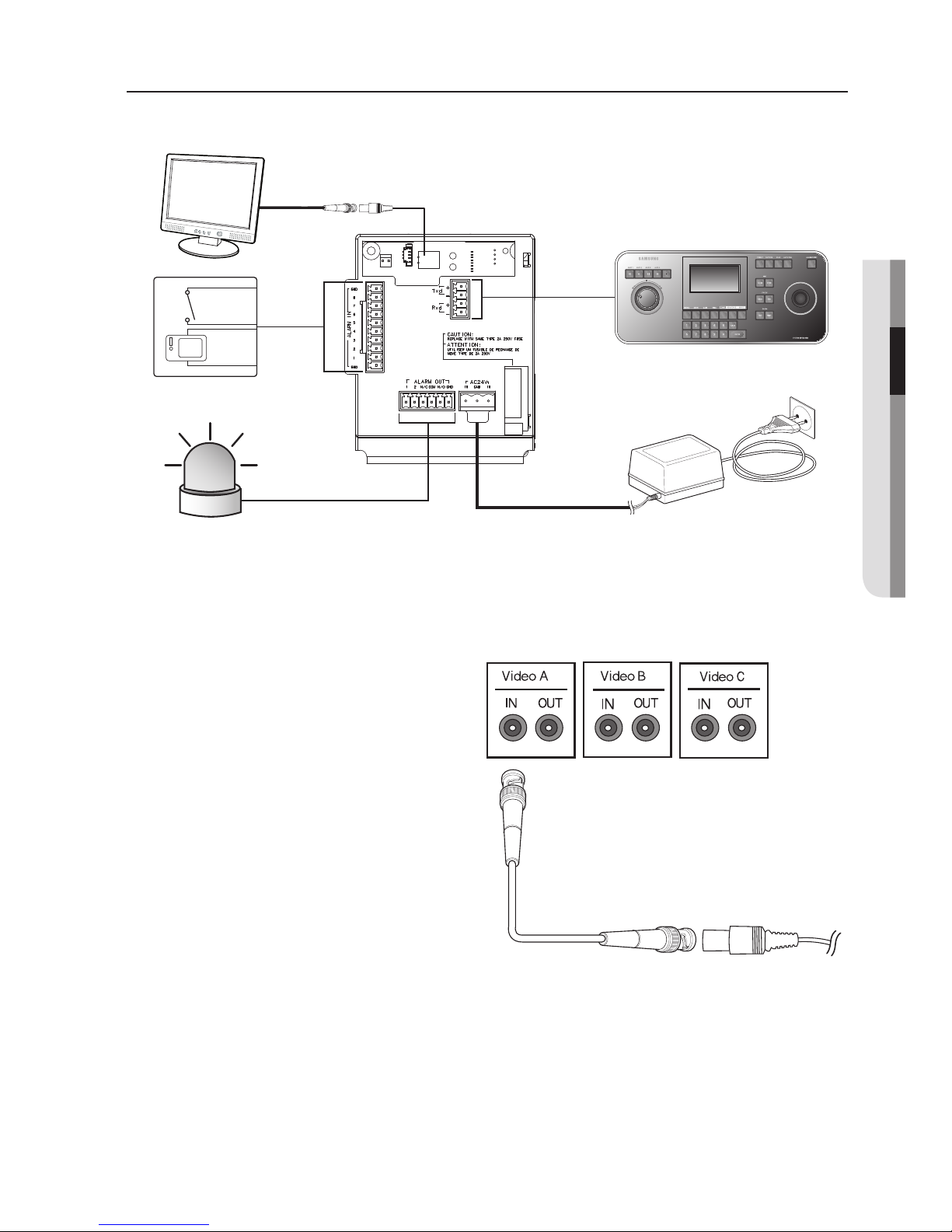
CONNECTING WITH OTHER DEVICE
Connecting to a monitor
Connect one end of the BNC
video cable connector to the
Video Output Terminal (VIDEO
OUT).
Connect the other end of the
connector to the Video Input
Terminal of the monitor.
1.
2.
Video terminal on the
rear of monitor
BNC Cable
MONITOR
ALARM IN
POWER SOURCE
ALARM OUT
CONTROLLER/DVR
 Loading...