

Samsung RS 24, RS 25, RS 27, RS 26, RS 24 Series Service Manual
...
RS 24
***
RS 25
***
RS 26
***
RS 27
***
Model:
SIDE-BY-SIDE REFRIGERATOR
SAMSUNG Home Appliance Service
For the latest parts information,
Please access to our service web site
(http://www.e4buyer.com/refrigerator)
2
IMPORTANT SAFETY NOTICE
The service guide is for service men with adequate backgrounds of
electrical, electronic, and mechanical experience. Any attempt to repair
a major appliance may result in personal injury and property damage.
The manufacturer or dealer cannot be responsible for the interpretation
of this information.
All rights reserved. This service guide may not be reproduced in whole or in
part in any form without written permission from the SAMSUNG ELECTRONICS
Company.
WARNING
3
Contents
1. Introduction 4
2. Installation
5
3. Nomenclature
6
4. Specifications
7
5. Interior Views and Dimensions
8
6. Refrigeration Cycle and Cool Air Circulation Route
10
7. Mechanical Disassembly
12
8. Operation Function
22
9.
Circuit Descriptions
37
10. Diagnostics
46
11. Illustrated Parts Catalog
58
12. Safety instruction on services
74
Appendix ⅠⅠ(Reference for circuit diagnostics) 75
Appendix ⅡⅡ(Circuit diagram) 80
4
1. INTRODUCTION
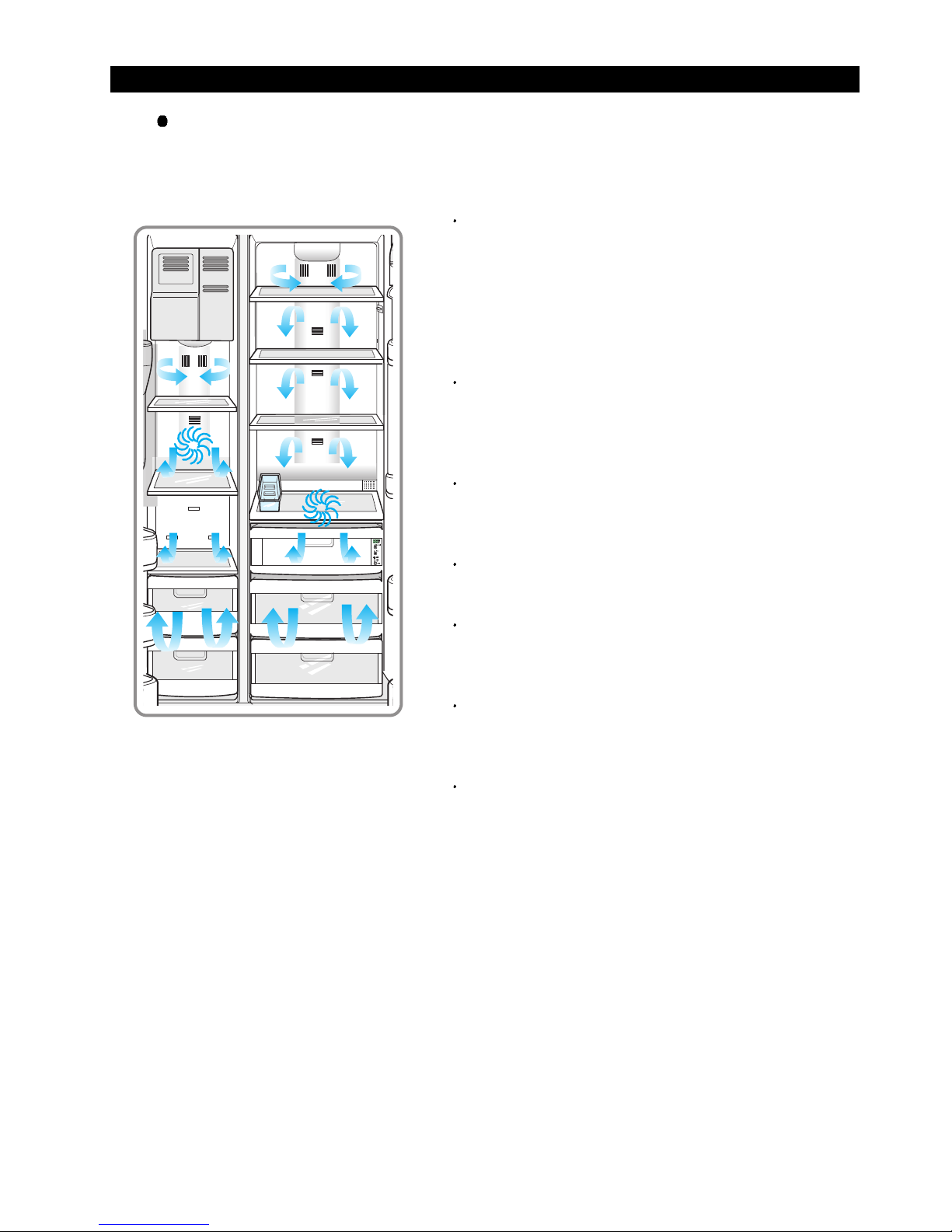
A newly developed SAMSUNG side by side refrigerator in 2002 has the following
characteristics.
1) T win Cooling System
The refrigerator and the freezer have two
evaporators. Given this independent system, the
freezer and the refrigerator are cooled individually as
required and are, therefore, more efficient. Food
odor from the refrigerator does not affect food in the
freezer due to separate air flow circulation.
2) Multi-Flow System
Cool air circulates through multiple vents on every
shelf level. This provides even distribution of cooling
inside cabinets to keep your food fresh longer.
3) Xtra Space
TM
Vertical room next to the ice maker in the freezer
provides space for pizza etc.
4) Door Alarm
Beep sound reminds you the door is open.
5) Xtra Fresh
TM
Optimized humidity control keeps vegetables & fruits
fresh.
6) Deodorizer
Reusable deodorizer keeps the refrigerator air
fresh and odor free.
7) CoolSelect ZoneTMDrawer (Optional)
User can select Quick Cool, and Select for quickly
soft freeze, chill, and cool. Select Soft freeze,Chill or
Cool to control the temperature of the drawer.
5
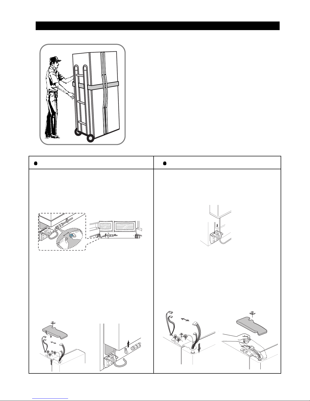
2. INSTALLATION
1) T o protect refrigerator in movement
Use padded hand truck as shown. If entrance width is
less than 1m, remove doors prior to installation and
reattach doors according to procedure below.
2) Remove all protective tape and pad in refrigerators.
Connect water lines and power cord. Adjust the
clearance between the doors.
3) Set the temperature control to the temperature and
wait for an hour.
The refrigerator should get slightly chilled and the motor
runs smoothly .
4) Once the refrigerator temperature is sufficiently low
You can store food in the refrigerator. After starting the
refrigerator, it takes a few hours to reach the appropriate
temperature.
Removing Doors
Open the freezer and refrigerator doors, and
then take off the front leg cover assembly by
turning the three screws counter-clockwise.
Remove the screw from clamp disconnect, the
water tube by pressing the coupler, and pulling
the water tube away .
With the door closed, remove the upper hinge
cover using a screwdriver, and then disconnect
the wires. Remove hinge screws and ground
screw counter-clockwise, and take off the upper
hinge. Take care removing the door to ensure that
it does not fall on you.
Remove the door from the lower hinge by
carefully lifting the door so as not to damage the
water tube. Remove the lower hinge from the
lower hinge bracket by lifting the lower hinge.
Attaching Doors
Insert the lower hinge in the bracket lower
hinge. Attach the freezer door by inserting the
hose in the lower side of the door into the hole in
the lower hinge and pulling the hose down.
Insert the upper hinge shaft into the hole. After
leveling between the upper hinge hole and the
hole of the cabinet. Reattach hinge screws and
screw in the clockwise direction. Connect the
wires. Put the front part of the upper hinge cover
on the front part of the upper hinge and reattach
from the front part of the upper hinge cover first.
6
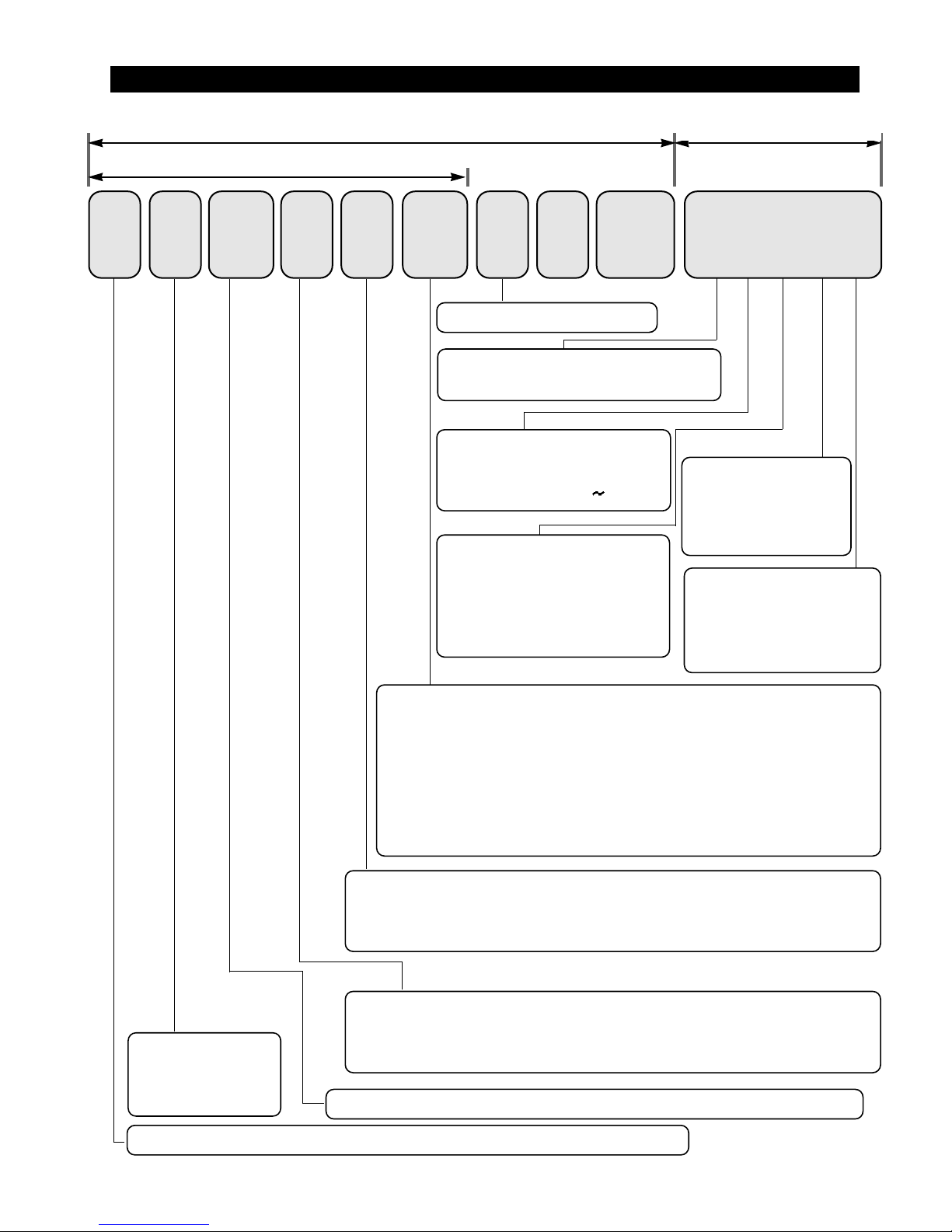
3. Nomenclature
R S 25
Product : R - SAMSUNG REFRIGERATOR B-OEM REFRIGERATOR
F A 1 /
XET
(E Q G FA I)
SW
GA TEGOR Y
S : SBS
H : NETWORKING
Function ;
N : BASIC MODEL
D : DISPENSER
J : DISPENSER+CoolSelect Zone
TM
HANDLE TYPE (DESIGN)
A : A-TOP HANDLE
L : LONG BAR- TRIM KIT
DOOR PLA TE COLOR
NORMAL ;
TRIM KIT ;
C : SKI BAR TYPE
E : K-TOP HANDLE(only for N-PRJ)
G : LONG BAR
B : HOME BAR MODEL
F : FULL
K : FULL + CoolSelect Zone
TM
NET CAP A : 24, 25,26, 27(cu.ft)
SL - NOBLE ST AINLESSSW - SNOW WHITE
DB - DAISY BEIGE
LB - ILLUMANA TE BLUE
TR - TROPICAL RED
NK - NA TURE KHAKI
DW - DARK WALNUT
SG - SIL VER GLASS
MR - MIRROR
AL - ALUMINUM
NC - NA TURAL CHERR Y
BUYER NO.
CONTROL METHOD : E-ELECTRONIC
S- SEMI ELECTRONIC
POWER
C - 1 15V/60Hz
H - 220V/50,60Hz
DOOR PLA TE
G - EMBOSSED + SECC
H - V/STEEL + SECC
P - PET + SECC
R - REAL ST AINLESS
X- TRIM KIT
OPTION
F* : FULL OPTION
D* : DISPENSER
M* : HOME BAR
N* : BASIC
FIL TER/KEY
I : INTERIOR FIL TER
O : EXTERIOR FIL TER
Y : KEY
N : KEY
K - 220V/50Hz
P - 127V/60Hz
Q - 230
240V/50Hz
MANUF ACTURE MODEL
MANUF ACTURE SPEC.
BUSINESS MODEL BAR CODE
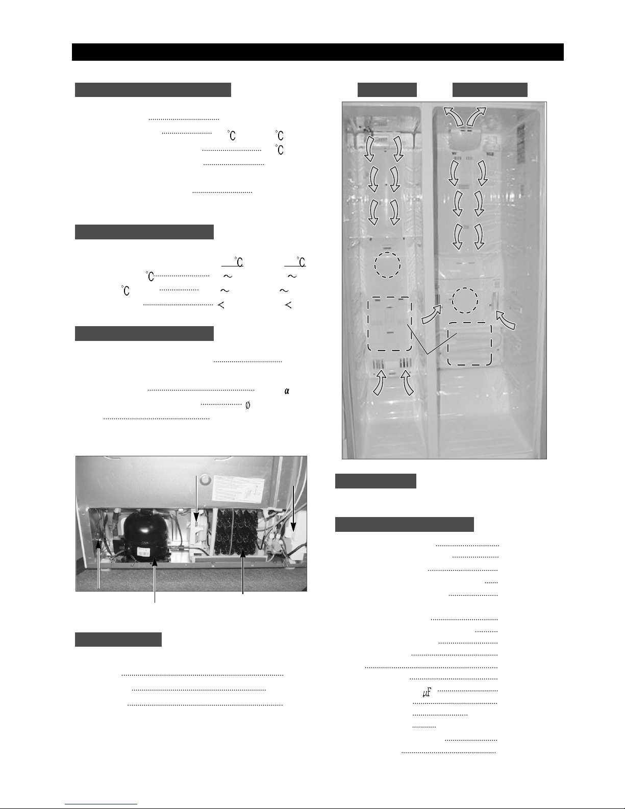
4. Specifications
Defrost Control From 24 to 32 hrs
Thermo-Bimetal 12
(off)/-5 (on)
Defrost Thermistor(502AT) 12
(off)
Maximum Current Leakage 0.25 mA
Maximum Ground Path Resistance 0.1 Ohm
Energy Consumption KWH/mo.
Ambient Temperature 20
32
Refrigerator, 1 7 1 7
Freezer,
-14 -25 -14 -25
Run Time,%
40 60
Refrigerant Charge (R134a) 220g
Compressor (Refer to Component Partlist)
Compressor oil Freol -15
Capillary tube(Dia, Length)
0.85, 3300mm
Dryer
Molecular Sieve XH-9
Clearance must be provided for air circulation
AT TOP 5cm
AT SIDES 0.25cm
AT REAR 5cm
RS24**, RS25**, RS26**, RS27
**
Main Board(Good) DA41-00139A
Main Board(Better&Best) DA41-00107A
Thermistor(Freezer) DA32-10109W
Thermistor(Freezer Evaporator) DA32-00006A
Thermistor(Refrigerator) DA32-10105U
Thermistor(Refrigerator Evaporator)
DA32-00006B
Thermistor(Ambient) DA32-10109V
Thermistor(CoolSelect ZoneTM)
DA32-10109X
Thermistor(Ice-Maker)
DA32-10108B
Thermo-Bimetal DA47-10160E
Relay DA35-10013Q
Overload Relay DA34-10003D
Run Capacitor (12 ) 2501-001045
Fan-Motor(FRE) DA31-00020E
Fan-Motor(REF) DA31-00002S(Good)
Fan-Motor(REF) DA31-00020E(Better&Best)
Fan-Motor(Condenser) DA31-00020H
Thermal Fuse DA47-00095C
Fan
Fan
(Air inlet)
(Air inlet)
Heat exchanger
Compressor
Dryer
C-Fan
Electric box
Sub-condenser
ELECTRICAL SPECIFICA TIONS Freezer Refrigerator
NO LOAD PERFORMANCE
REFRIGERA TION SYSTEM
INST ALLATION
MODELS
REPLACEMENT P ARTS
7
Fan
Fan
Heat exchanger
Heat exchangerHeat exchanger
(Air inlet)
(Air inlet)
Fan
Fan
(Air inlet)
(Air inlet)
8
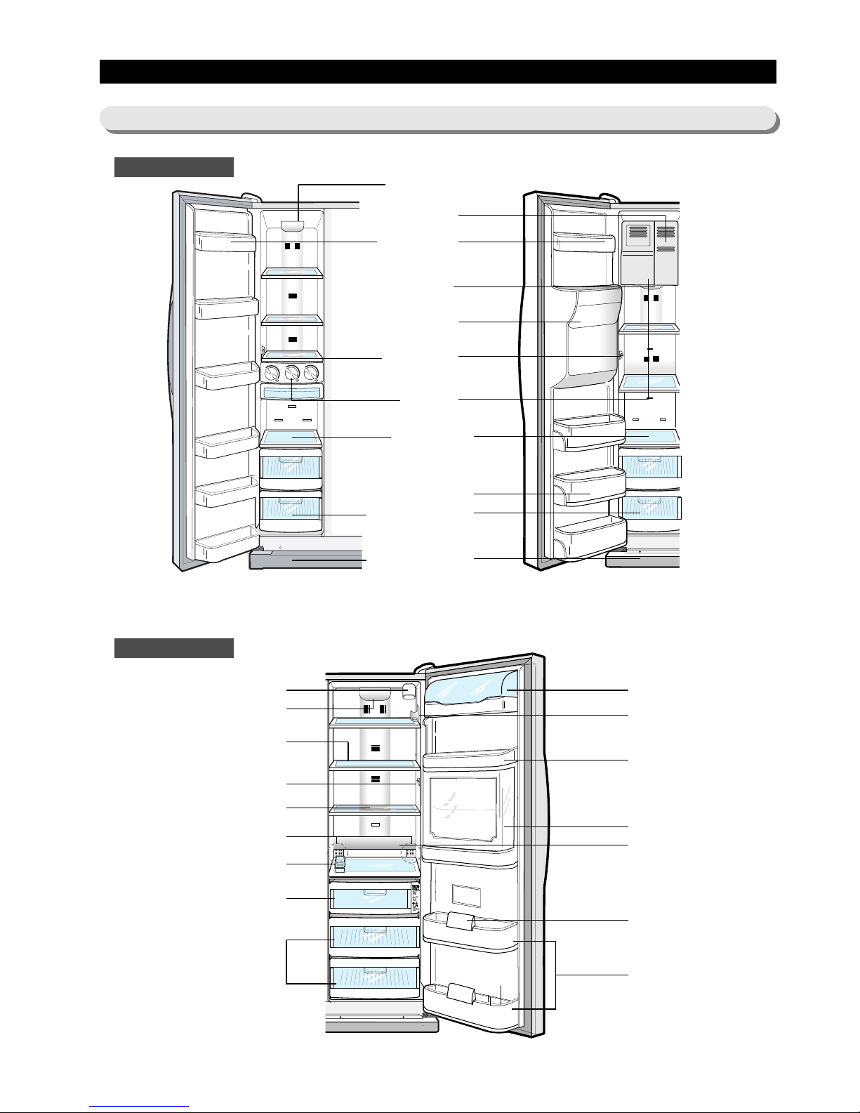
5. Interior Views and Dimensions
5-1) Shelves and Bins
Freezer
Refrigerator
Light
Light
Door Bin
Xtra Space
TM
Water Filter (optional) Dairy Compartment
Wine Rack(optional)
Muti-purpose Bin
Beverage Station (optional)
Lights (lower)(optional)
Door Bin Top Lips
Gallon Door Bins
Light (upper)
Spill-proof glass Shelf
Light Switch
Foldable Shelf (optional)
Twin Deodorizer(optional)
Egg Container
CoolSelect Zone
TM
Drawer (Chilled Bin for optional)
Vegetable & Fruit
Drawer (upper)
Ice Chute
Light Switch
Ice Maker
Glass Shelf
Pockets
Plastic Drawers
Front Leg Cover
RS 24/25/26/27
with Basic or Beverage Station
TM
RS 24/25/26/27
with Dispenser or Beverage Station
TM
9
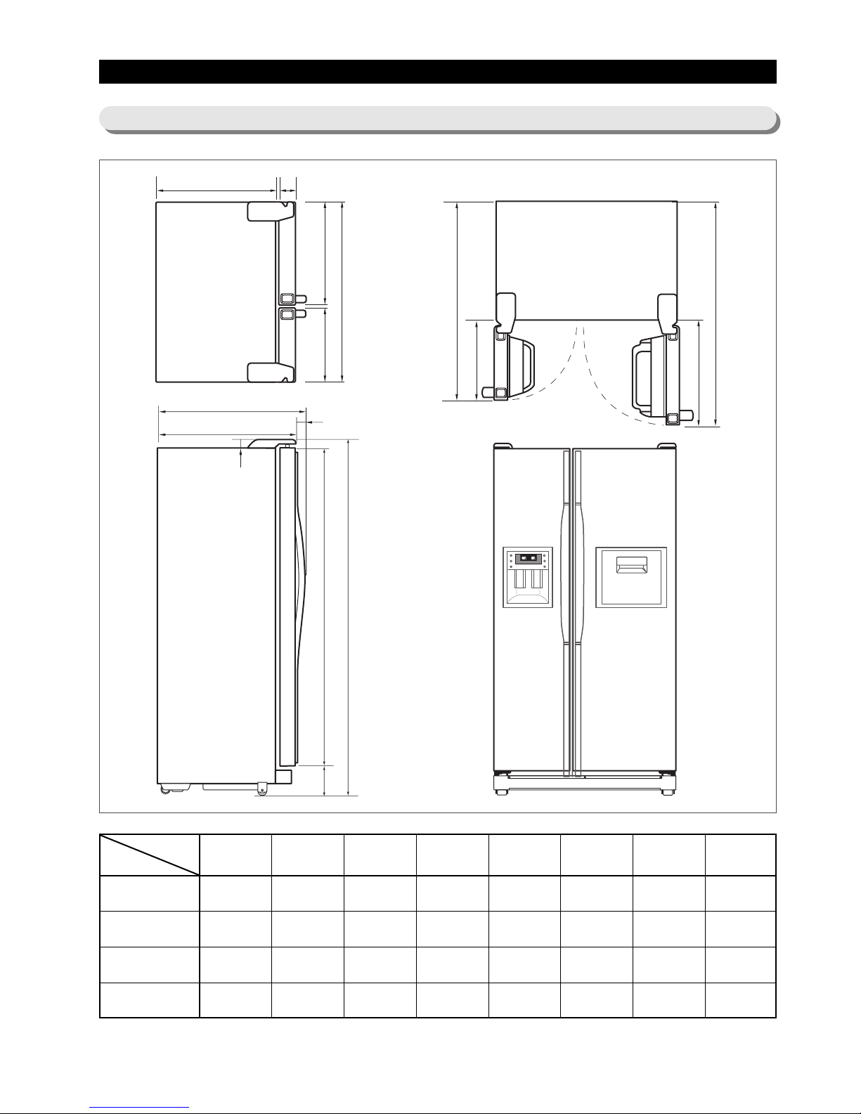
Interior Views and Dimensions
5-2) Dimensions of Refrigerator(RS24/25/26/27)
Beverage Station
TM
(option)
RS24
RS25
RS26
RS27
710
710
760
760
50
85
50
85
864
899
914
949
774
809
824
859
1 130.5
1 138
1 180.5
1 188
1255.5
1263
1305.3
1313
420.5
428
420.5
4280
545.5
553.0
545.3
553.0
AB CDE FGH
AB
511.5385.5
908
C
D
29
60
1637
1773
E
F
G
H
54
10
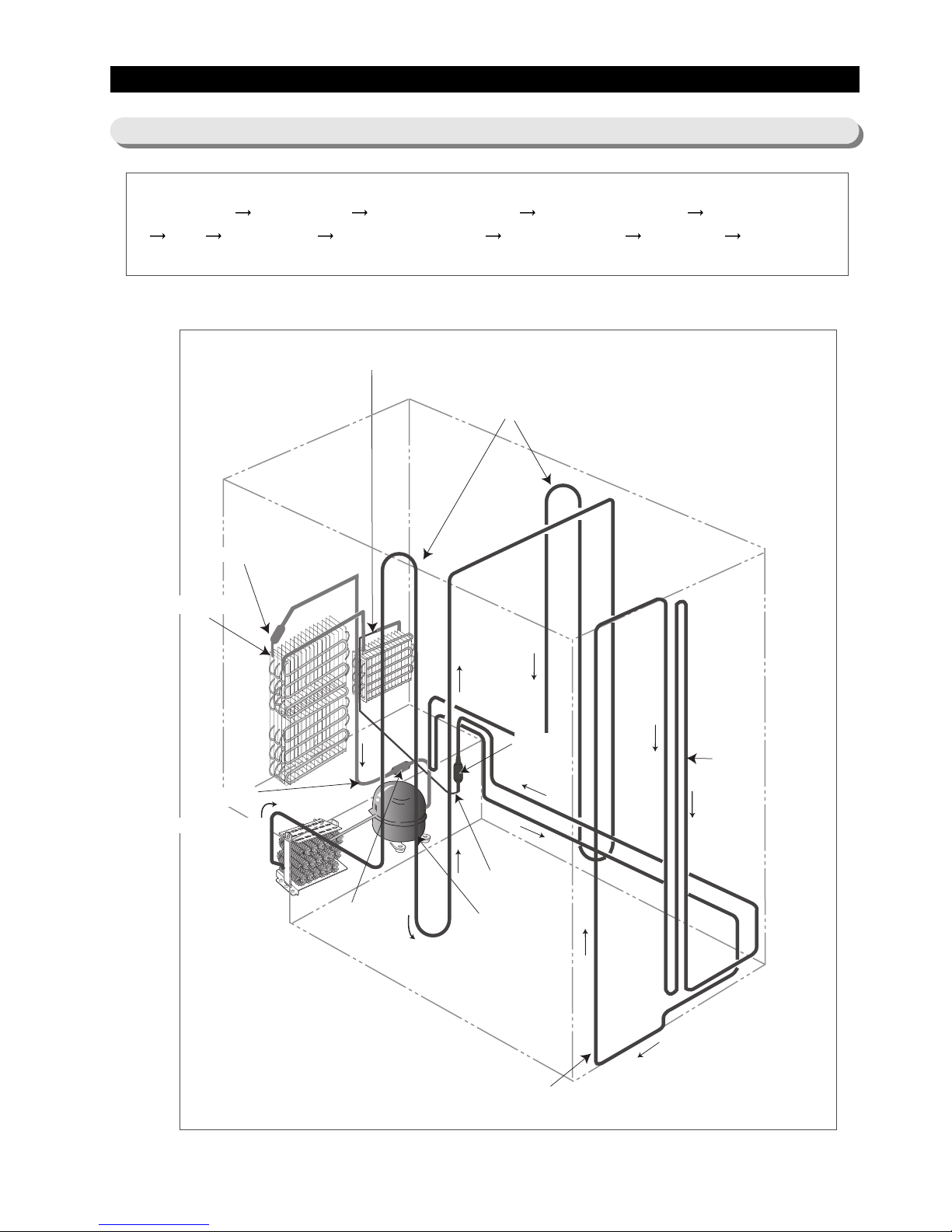
Compressor Sub-condenser Side Cluster Pipe(FRE) Side Cluster Pipe(REF) Hot Pipe
Dryer Capillary Tube Refrigerator Evaporator Freezer Evaporator Suction Pipe Compressor
Refrigerator Evaporator
Capillary Tube
ACCUMULATOR
Freezer Evaporator
SUCTION PIPE
Dryer
Muffler
SUB-CONDENSER
Hot Pipe
Hot Pipe
Compressor
SIDE CLUSTER PIPE
6. Refrigeration Cycle and Cool Air Circulation Route
6-1) Refrigerant Route in Refrigeration cycle
11
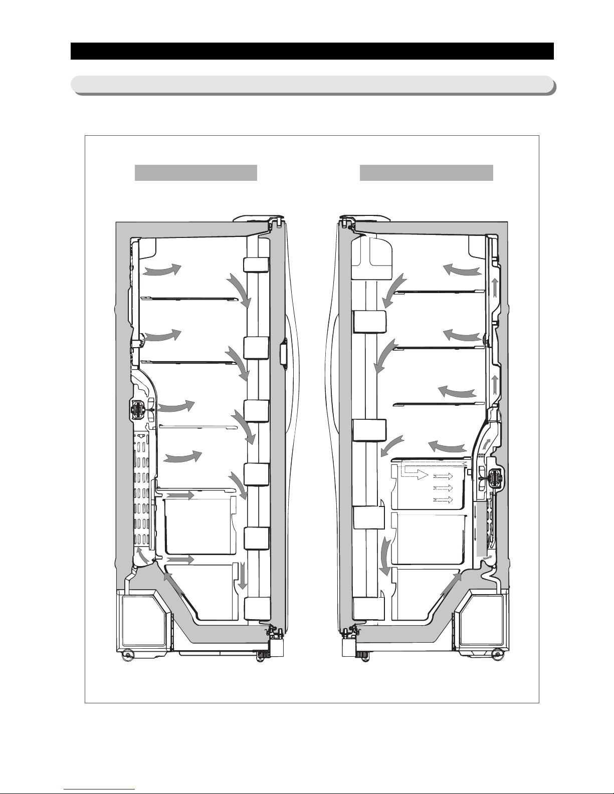
Refrigeration Cycle and Cool Air Circulation Route
6-2) Cool Air Circulation
Freezer
Refrigerator
12
7-1) Refrigerator Disassembly
7-2) Freezer Disassembly
7-3) Machine Compartment Disassembly
7. Mechanical Disassembly
Control Panel 14
Door Handle
14
Beverage Station
TM
14
Door Gasket 14
Refrigerator Door Light Switch 15
Refrigerator Light 15
Tempered Glass Shelf 15
Plastic Drawers in Refrigerator 15
Gallon Door Bin 15
Water Filter 16
Evaporator Cover in the Refrigerator 16
Upper Ductwork 16
Evaporator Fan Motor 16
Evaporator in Refrigerator 17
Refrigerator Thermistor 17
CoolSelect Zone
TM
Thermistor 17
Door Bin in Freezer 18
Freezer Door Light Switch 18
Plastic(Wire) Drawer in Freezer 18
Freezer Shelf 18
Ice Dispenser Ice Maker 18
Auger Motor Case 19
Freezer Light 20
Evaporator Cover in Freezer 20
Upper Ductwork 20
Evaporator Fan Motor 20
Evaporator in Freezer 21
Freezer Thermistor 21
Ambient Thermistor 21
Ice-Maker Thermistor 21
Machine Compartment Electrix Box 22
Water Solenoids 22
Condenser Fan 22
Sub-condenser 22
13
77.. MMeecchhaanniiccaall DDiissaasssseemmbbllyy
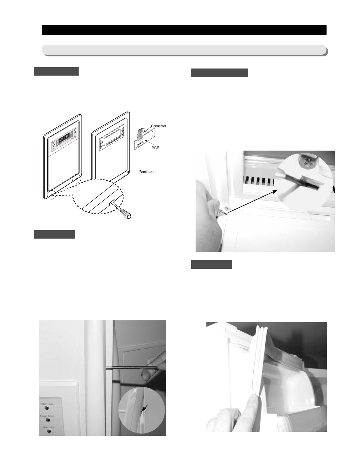
1. Insert a flat-blade screwdriver on the slot as shown,
and unlock the tabs.
2. Disconnect the wire connector in the back of control
panel.
The door handles allow access into the refrigerator
and freezer. They are front mounted with Phillips
head screws.
1. With a small flat-blade screwdriver, press the
small button and pull handle cover out.
2. Remove the Phillips screws (8).
3. Lift the handle with an in and upward motion until
it disengages the locking tabs. Pull the handle
outward to remove it.
The beverage station
TM
allows access to the
refrigerator without opening the refrigerator door.
1. Open the door beverage station
TM
2. With a small flat-blade screwdriver,take out the
rubbercap, then put it into the small hole and
push the button inside.
3. Take off its door.
The door gasket is a molded gasket set into a
channel located in the door liner.
1. Open the door.
2. Grasp the gasket and pull in an outward motion
until the molded gasket separates from the door
liner.
Control Panel
Door Handle
Beverage Station
TM
Door Gasket
Button
7-1) Refrigerator Disassembly
14
MMeecchhaanniiccaall DDiissaasssseemmbbllyy
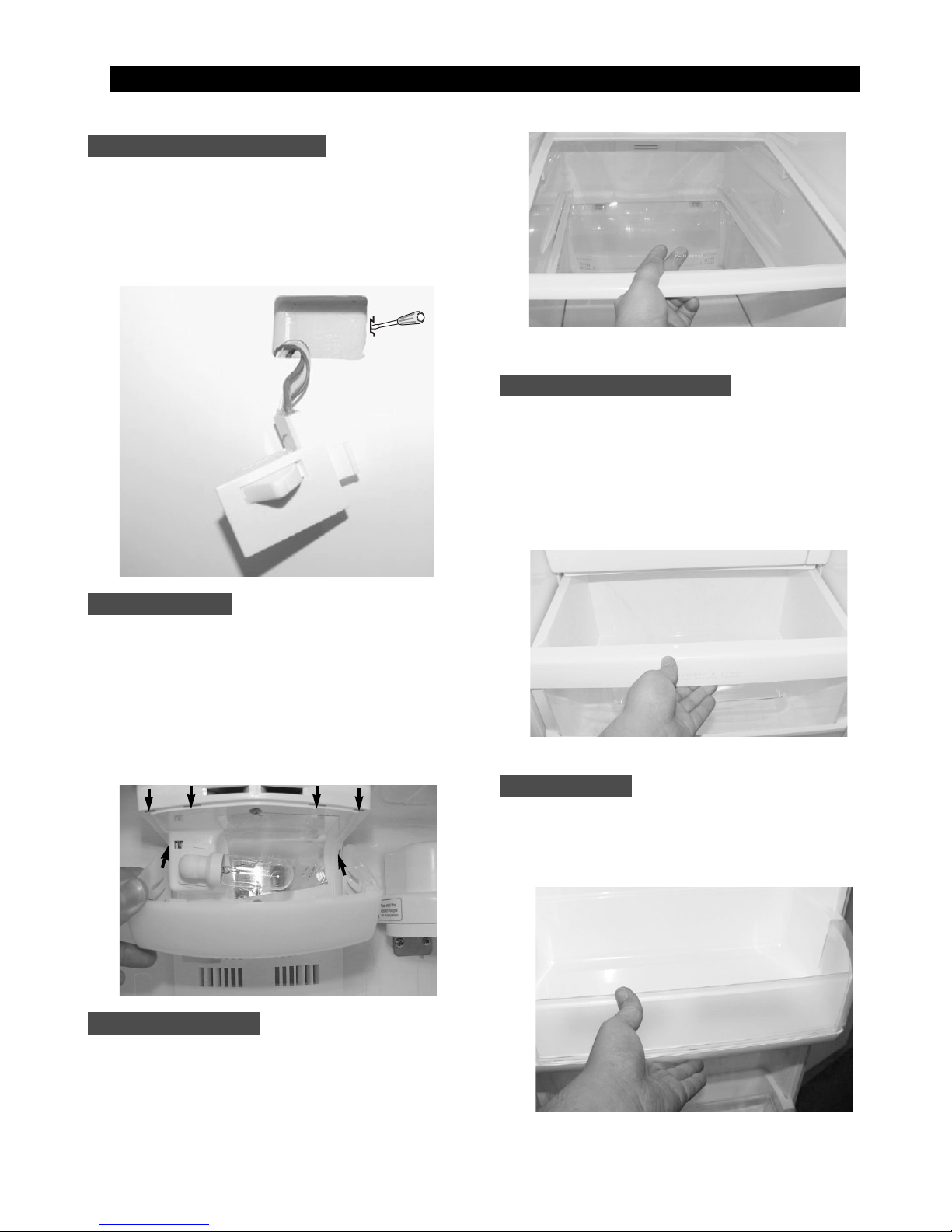
The refrigerator has a door light switch located in
the upper right corner for the refrigerator.
1. Use a small flat-blade screwdriver to unlock the
locking tab and pull the switch out until the
wire connector is visible.
The refrigerator lights are located in the upper and
lower portion of refrigerator.
1. Pull out the screw cap and remove the screw.
2. To access the lower lights, pull out the screw cap
and remove the screw.
3. Remove the lamp cover by unlocking the tabs
and pulling the cover down.
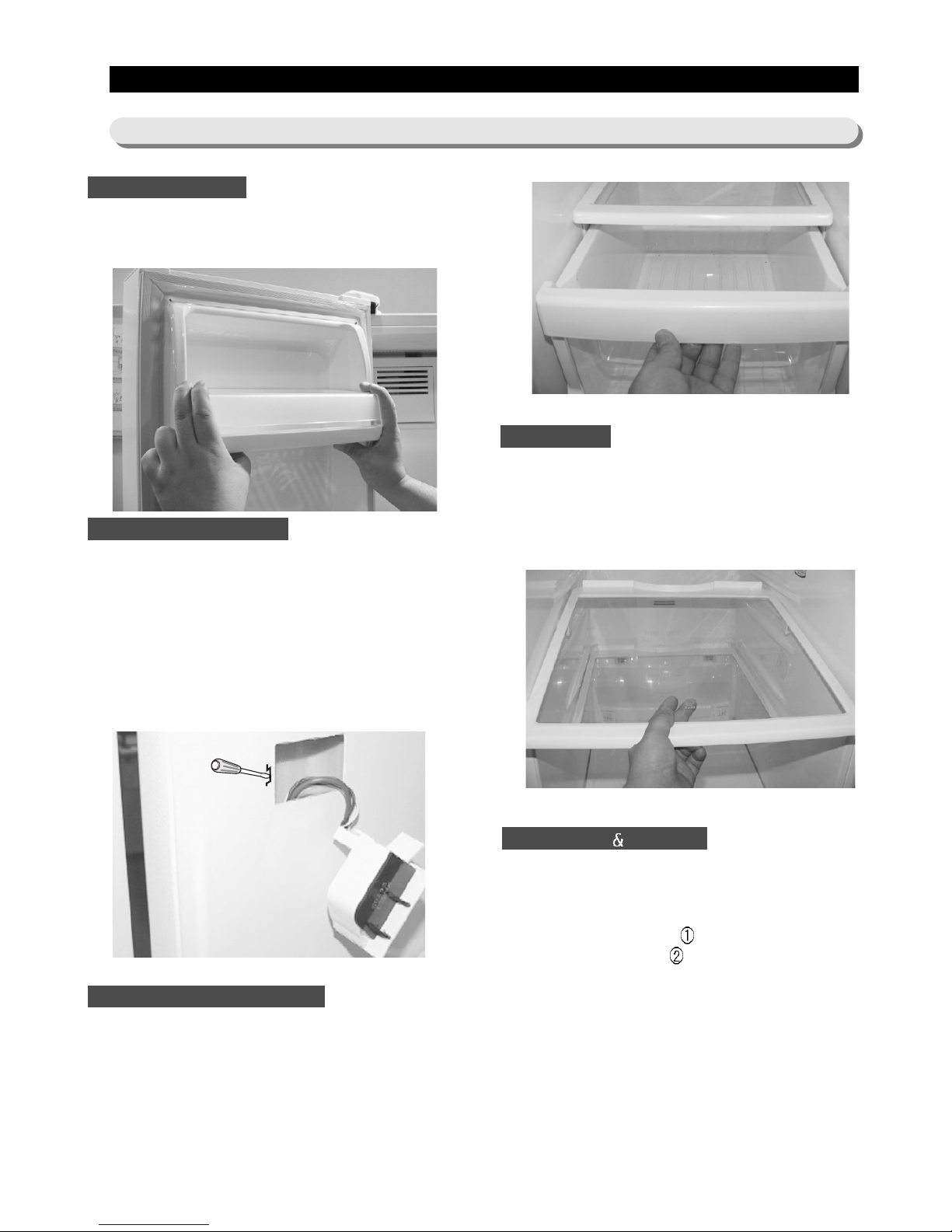
These shelves allow the storage of larger items and
pull out for easy access.
1. Pull the shelf out as for as it goes.
2. Lift it up and remove it.
Drawers are designed for storage of fruits,
vegetables, and deli items. The drawers are located
in the lower portion of the refrigerator.
1. Pull out the drawer as far as it goes.
2. Tilt the drawer up and pull it out until it is
removed.
The door bins allow storage of perishable items.
1. Push the bin up and slide it out.
Refrigerator Door Light Switch
Gallon Door Bin
T empered Glass Shelf
Plastic Drawers in Refrigerator
Refrigerator Light
15
MMeecchhaanniiccaall DDiissaasssseemmbbllyy
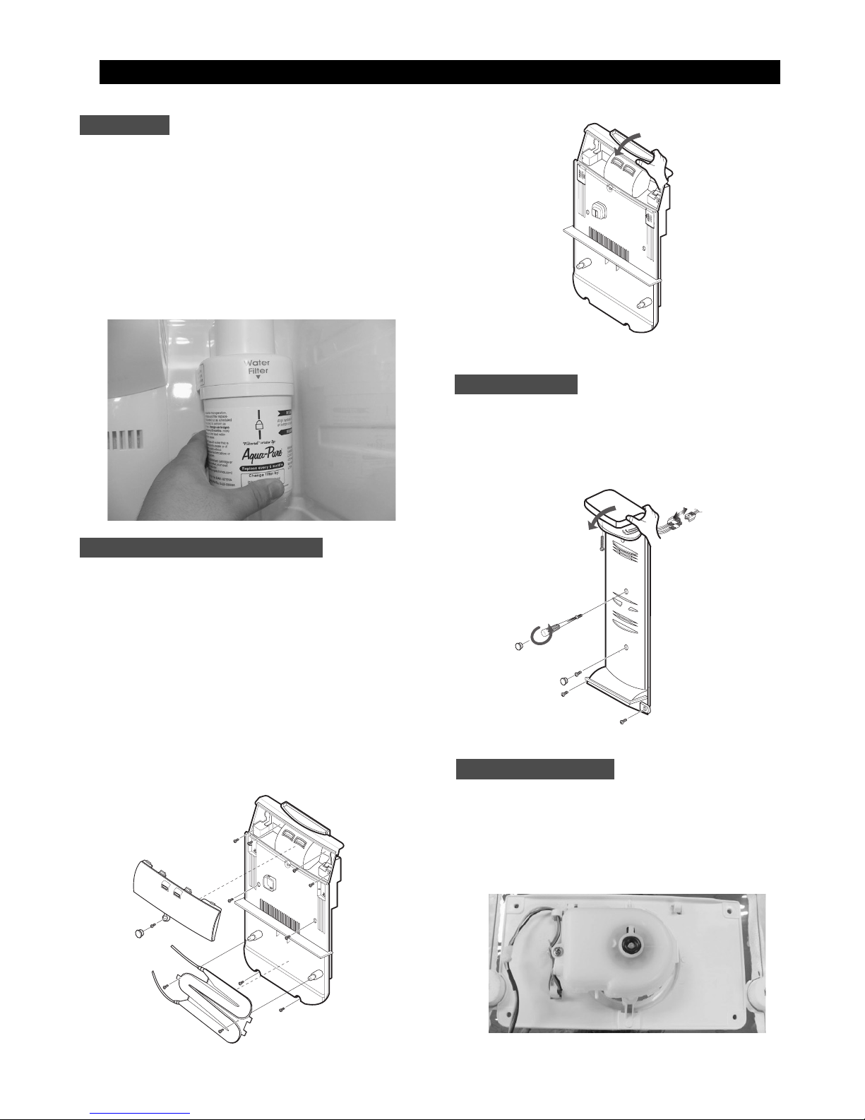
The water filter is located in the upper right-hand
corner of the refrigerator. The water filter filters water
for the ice maker and the water dispenser.
1. Turn the water filter 1/2 turn counterclockwise and
pull it down.
2. To install the filter, align the indication mark
(unlock position) and push it up while turning 1/2
turn clockwise until the lock position is aligned.
Do not over tighten.
1. Pull out the screw cap and remove the screw.
2. Remove the lamp cover by unlocking the tabs
and pulling the cover down.
3. Remove the water tank from the evaporator cover
by unscrewing the screws (2).
4. Remove the screws (6) at the evaporator cover
and the two fixed screws of the wire connector
cover.
5. Take off motor and lamp wire connector located
on the upper liner.
6. Remove the duckwork of the evaporator fan in the
direction of the arrow as shown.
1. Remove the screw caps (2) and screws (5).
2. Slide the upper fan ductwork out while
disconnecting the wire connector(lamp and
thermistor).
The evaporator fan is located in the middle rear of
the freezer. This fan circulates cold air in the freezer.
1. Remove screws (4) located at the four corners of
the fan bracket.
2. Take the fan motor assembly off.
Water Filter
Evaporator Cover in the Refrigerator
Upper Ductwork
Evaporator Fan Motor
16
MMeecchhaanniiccaall DDiissaasssseemmbbllyy
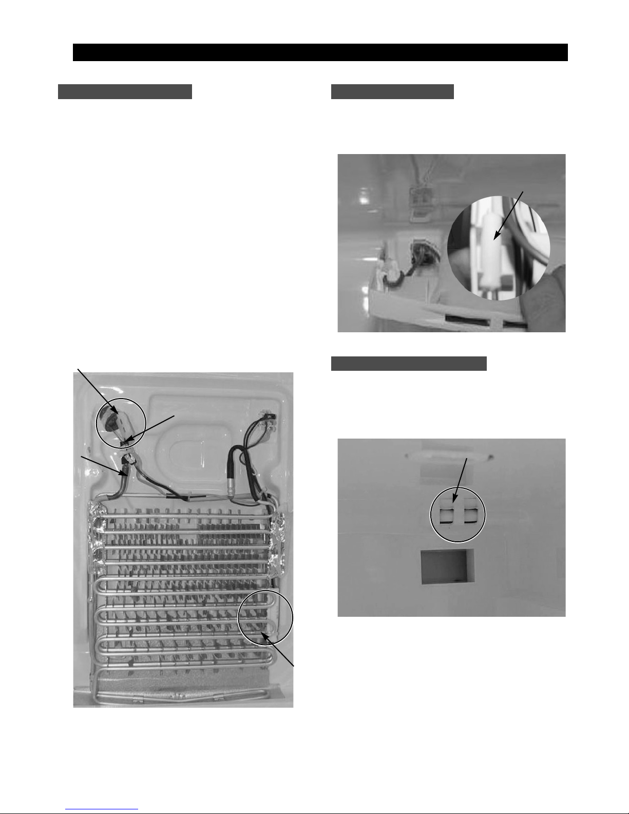
Evaporator is located in the bottom of refrigerator.
1. Take off the ductwork in refrigerator.
2. Disconnect the wire connector.(Heater and
Thermistor)
3. Desolder the capillary tube and the suction line
from the evaporator.
4. Remove the evaporator.
5. With a file, score the capillary tube just upstream
of the soldered point. Break off the soldered
section to help prevent solder from plugging the
tube during soldering.
6. Place a new evaporator and braze the suction
and capillary tube to evaporator using silver
solder.
7. Install a replacement dryer.
8. Evacuate and recharge the system using
reasonable procedures.
The refrigerator thermistor is located inside of the
upper light cover of the refrigerator.
The CoolSelect Zone
TM
thermistor is located outside
the back of CoolSelect Zone
TM
drawer. The
temperature signal sends the micro-processor.
Refrigerator ThermistorRefrigerator Thermistor
CoolSelect ZoneTMThermistor
Thermistor
Thermistor
CoolSelect ZoneTMThermistor
Suction Line
Capillary Tube
Thermal Fuse
Evaporator in Refrigerator
17
The door bins allow storage of perishable items.
1. Push the bin up and slide it out.
This switch is located in the left-hand portion of the
freezer and sends a signal to the processor.
1. With a small flat-blade screwdriver, unlock the
locking tabs and pull the switch out until the wire
connector is visible.
2. Disconnect the wire connector and remove the
switch.
Drawers are designed for storage of meat and dry
foods. The drawers are located in the lower portion of
the freezer.
1. Pull out the drawer as far as it goes.
2. Tilt the drawer up and pull it out until it is
removed.
The shelves slide out for easy access for frozen
items.
1. Slide the shelf out until it reaches its stop.
2. Tilt down and slide it out of thecompartment.
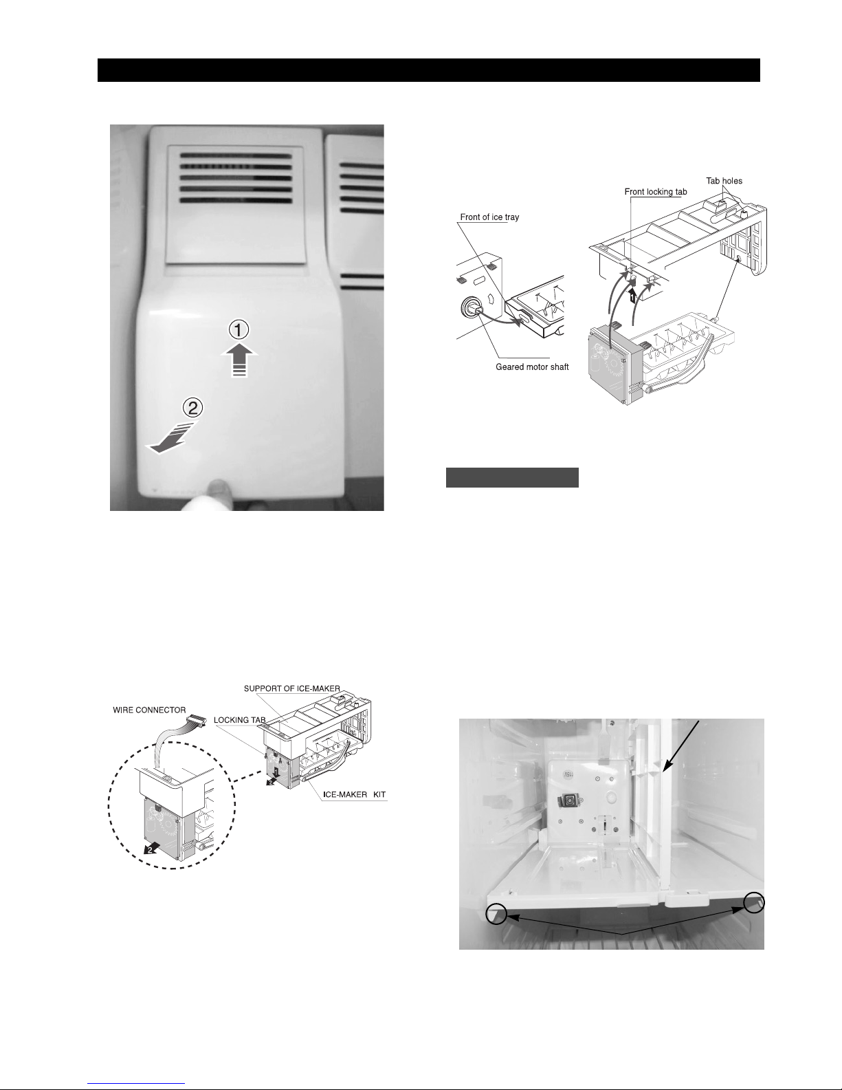
The ice dispenser is located in the upper portion of
the freezer. This assembly stores ice made by the
icemaker and dispenses ice.
1. Lift the ice bucket up
and slide out the ice
dispenser assembly
.
Door Bin in Freezer
MMeecchhaanniiccaall DDiissaasssseemmbbllyy
7-2) Freezer Disassembly
Freezer Shelf
Plastic (Wire) Drawer in Freezer
Freezer Door Light Switch
Ice Dispenser Ice Maker
18
MMeecchhaanniiccaall DDiissaasssseemmbbllyy
The ice maker is located inside of the ice dispenser
assembly.
1.
Remove ice maker support screws (2), and slide out.
2. Disconnect the ice maker wire connector.
3.
Unlock the locking tabs to separate the ice maker kit.
In order to assemble the icemaker kit.
1. Assemble the geared motor shaft and the front of
ice tray.
2. Lift the front locking tab and assemble the ice
maker kit.
3. Connect the ice maker wire connector.
4. Match the tab holes and tabs(2) located on the
top of the liner, and slide the ice maker in.
5. Tighten the screws (2) of the ice maker support.
This shelf is designed to support the ice maker &
ice dispensed and Xtra Space
TM
.
1. Remove the Xtra Space
TM
cover to push it down
near the partition.
2. Slide the partition out.
3. Remove the screws (2) on the bottom front of the
case.
4. Slide out the case while disconnecting the wire
connect.
Auger Motor Case
Partition
Screws
19
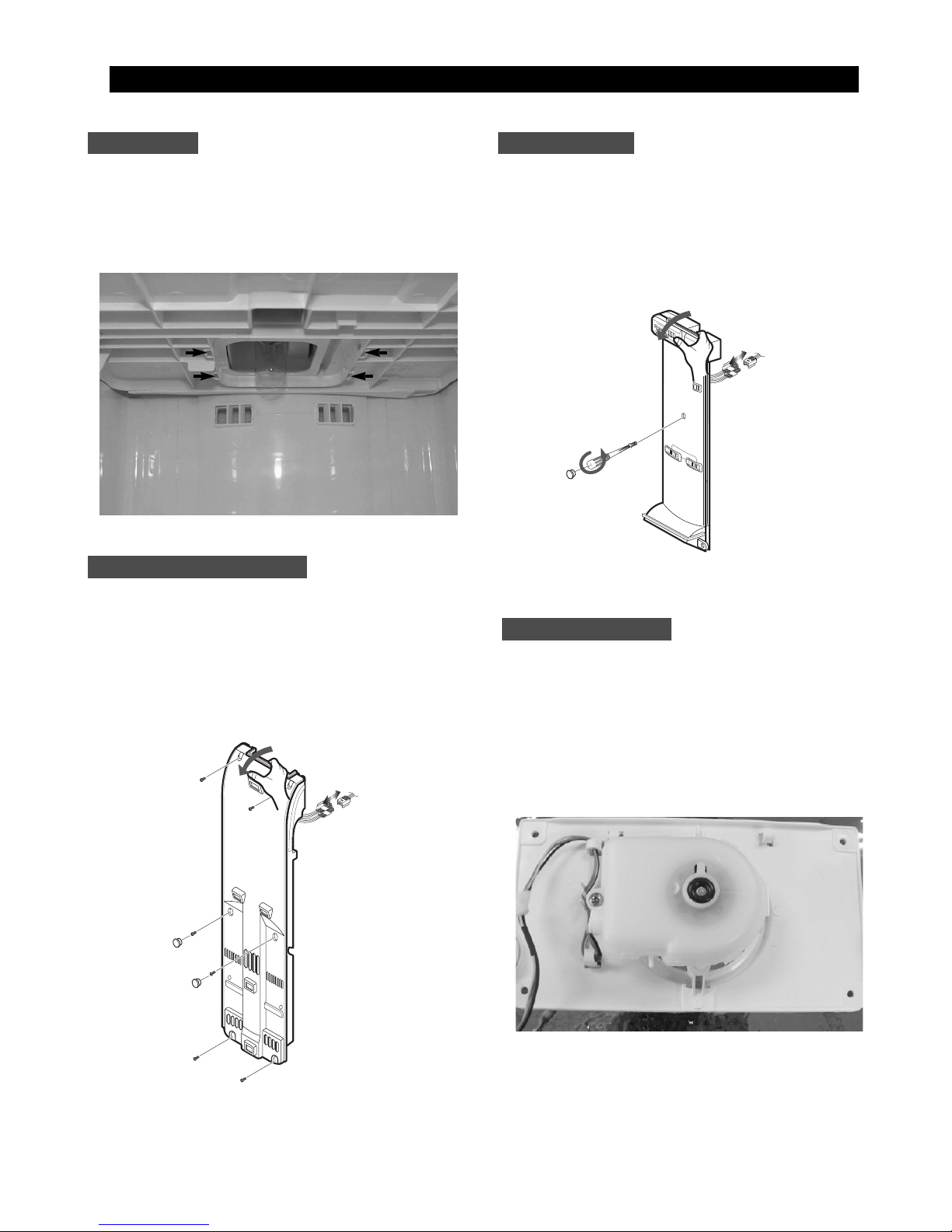
The freezer light is located in the bottom of the
auger motor case. The light is covered by an opaque
cover.
1. Remove the screw and the light cover.
1. Pull out the screw caps and remove screws (6).
2. Remove the ductwork of the evaporator fan in the
direction of the arrow as shown.
3. Disconnect the wire connector.
1. Remove the screw cap and screw.
2. Slide the upper fan ductwork out while
disconnecting the wire connector (Lamp and
Thermistor).
The evaporator fan is located in the lower rear of
refrigerator. This fan circulates cold air in the
refrigerator.
1. Remove screw(4) located at the four corners of
the fan bracket.
2. Take the fan motor assembly off.
Upper Ductwork
Evaporator Fan Motor
Freezer Light
Evaporator Cover in Freezer
MMeecchhaanniiccaall DDiissaasssseemmbbllyy
20
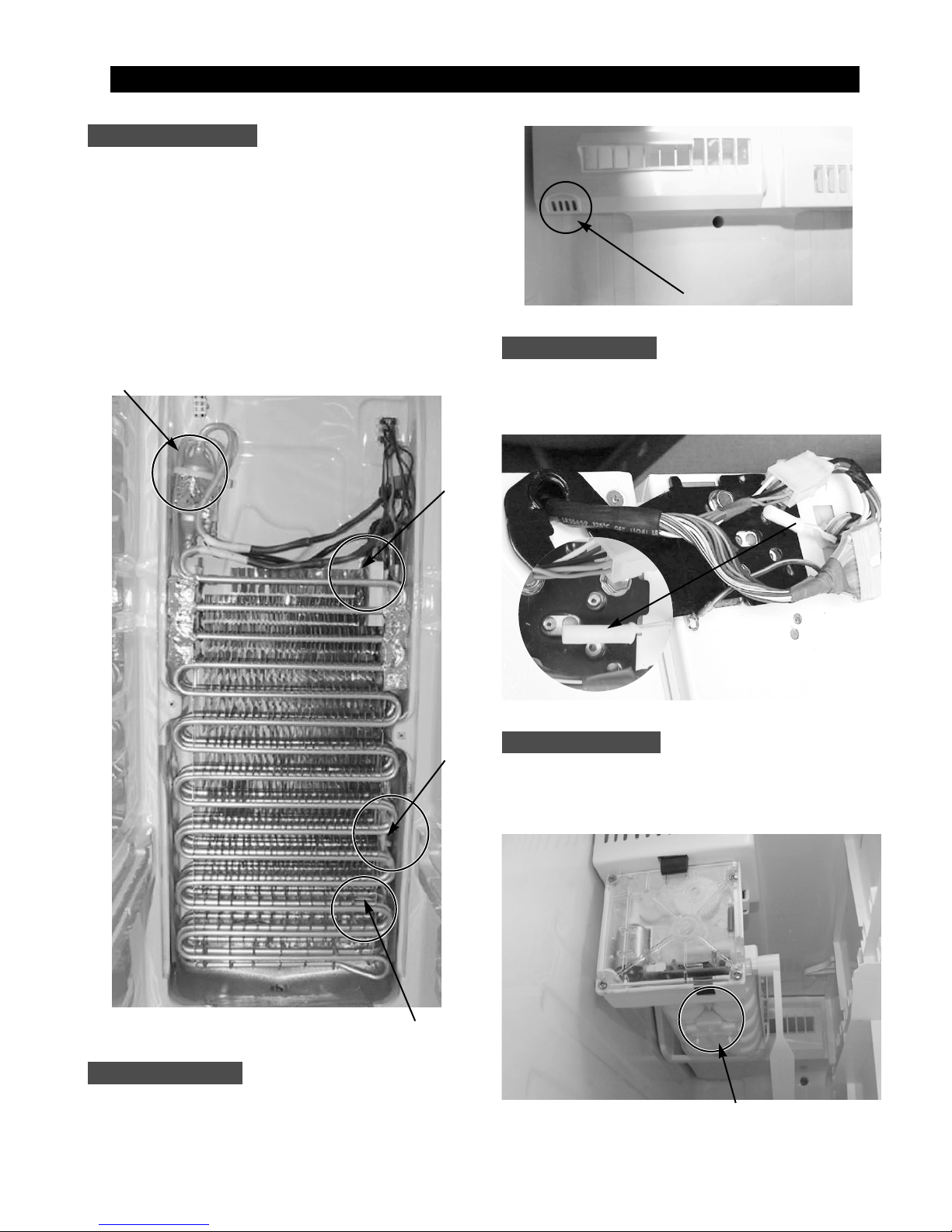
Evaporator is located in the bottom of freezer to
produce cold air driven across the evaporator coils.
1. Take off the ductwork in Freezer.
2. Disconnect the wire connector (Heater, Bimental,
and Thermistor).
3. Desolder the inlet and outlet tubes.
4. Remove the evaporator.
5. Take the same steps to seal the system as
mentioned earlier.
The freezer thermistor is located at the top left of
freezer vent. It sends temperature signals to the
micro-processor.
The ambient thermistor is located inside the upper
hinge cover. It sends temperature signals to the
micro-processor.
The Ice-Maker thermistor is located in its bottom.
The temperature signal sends the micro-processor.
Evaporator in Freezer
MMeecchhaanniiccaall DDiissaasssseemmbbllyy
Accumulator
Bimetal
Thermistor
Thermal
Fuse
Freezer Thermistor
Ambient Thermistor
Ice-MakerThermistor
Freezer Thermistor
Ambient
Thermistor
Thermistor(Ice-Maker)

21
1. Disconnect the power cord of the refrigerator
.
2. Remove the fixed screws (6) of compressor
cover.
3. Slide up and take off the compressor cover to
see the machine compartment.
4. Press the tab in electric box cover to take out
by using a flat-blade screw driver.
When the solenoids receive a signal from the microprocessor, they supply water to the water dispenser
or the ice maker.
1. Remove bracket screw (1) on electric box.
2. Take the solenoids assembly out.
3. Disconnect water tubes (3).
The condenser Fan is located in the middle of
machine compartment. It cools down the subcondenser and the compressor.
1. Disconnect the condenser fan wire.
2. Remove screw (1) on the drain water tray.
3. Take the condenser fan assembly off.
The sub-condenser is located in the machine
compartment. The heat is extracted by condenser
fan.
1. Desolder the compressor discharge &
the sub-condenser outlet.
2. Take out the sub-condenser.
Machine Compartment &&Electric Box
MMeecchhaanniiccaall DDiissaasssseemmbbllyy
7-3) Machine Compartment Disassembly
(+)driver
(-)driver
PCB-MAIN ASSY
Water Solenoids
Condenser Fan
Sub-condenser
Desoldering Point
22
8. Operation Function
8-1) Digital Panel 23
8-2) Temperature Control Function
24
8-3) Power Freeze and Power Cool Functions
25
8-4) Child Lock Function
25
8-5) Ice
Water Dispenser Function 26
8-6) C-Fan Motor Delay Function of the Machine Compartment
26
8-7) CoolSelect Zone
TM
Function(optional) 26
8-8) Water Filter Indicator Function
27
8-9) Ice-Maker Function
27
8-10) Defrost Function
29
8-11) Forced Operation Function (Pull-down/R-Defrost/R,F-Defrost/Cancellation)
30
8-12) Sound Function
31
8-13) Exhibition Function
31
8-14) Self-Diagnostics Function
31
8-15) Load Operation Check Function
33
8-16) Restoration Function for Power Outage
33
8-17) Set Point Shift Function
33
8-18) Table of Set Point Shift Function
34
23
8. Operation Function
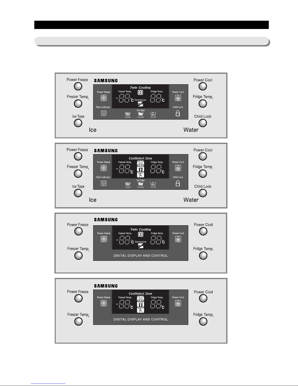
8-1) Control Panel
● For general control panel (Full option & Basic Model)
24
8. Operation Function
When the system power is initally engaged, the default set temperature are -20 for the freezer and 3 for the set
refrigerator, respectively. The numbers shown on the digital display panel stand for the actual compartments
temperatures. When the compartment temperatures go down, so do the numbers on the display panel, and finally they
reach the set temperatures. Once the system is stabilized, the display temperatures are the set temperature.
1) Freezer Temperature Control.
To select a set temperature, press the Freezer Temp. button. The display shows the set temperature from -14
to
-25
in sequence.
2) Refrigerator Temperature Control.
To select a set temperature, press the Fridge Temp. button. The display shown the set temperature from 1
to
7
in sequence.
note) Because of the temperature sensor sensivity , the refrigerator can be under and/or over cooled when
the air flow is blocked by stored foods. (Temperature range of the sensor :
-9∼30
)
In the event of a power failure, if the freezer temperature is maintained lower than
5
, the last
selected set temperature and functions memorized in EEPROM will be restored when the power is on.
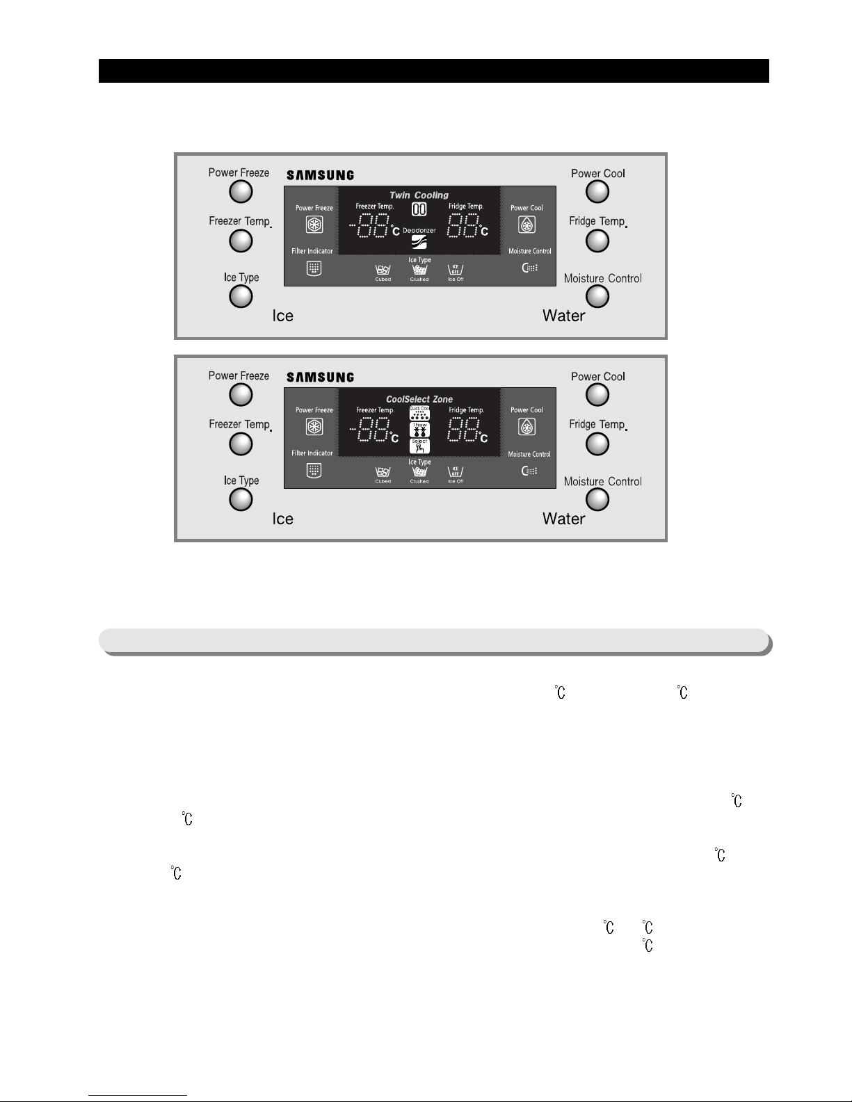
Note) Initially the light of moisture control button is on. If the moisture in the dispenser or Beverage Station
TM
is
found, press this button. So the light will be on, and eliminate the moisture.
8-2) T emperature Control Function
● The control panel is applied only for Europe Area
25
Operation Function
8-3) Power Freeze and Power Cool Functions
8-4) Child Lock Function
● Select the Power Freeze or Power Cool buttons separately .
● These buttons are toggled ON and OFF and the indicators as well.
● Although you select Power Freeze or Power Cool, the set temperatures in the freezer and refrigerator are not
changed.
● The set temperatures for the compartments can be changed while these functions are in use.
1) Power Freeze function
1-1) When you press the Power Freeze button, the LED indicator lights right away, but there is 10 seconds lag time
to an actual
operation. When this button is pressed again, the Power Freeze function stops and the indicator is off
immediately .
1-2) If you select Power Freeze, both the compressor and the freezer fan run for 10 hours continuously .
1-3) During Power Freeze, the freezer retains the current settings.
1-4) When Power Freeze expires, the indicator goes off and the freezer set temperature will be restored.
2) Power Cool function
2-1) Power Cool operation and the indicator work exactly same as the Power Freeze function.
2-2) When Power Cool is selected, COMP and R-FAN operate continuosly until the refrigerator reaches -4
. This
function will be terminated after 2
½ hr running.
3) When you select Power Freeze and Power Cool together
Each function works at the same time. The COMP and F-FAN run continuously and the R-FAN runs until -4
in the refrigerator.
4) Initial Power-On
4-1) The freezer and the refrigerator temperatures are higher than -10 and 10 espectively if, respectively. If Power
Freeze is selected, the R-FAN will be of f. If Power Cool is selected, the F-FAN will be off.
4-2) When both functions are selected, there is no benefit of fast cooling for each compartment.
● When the child lock button is pressed for 3 seconds, the child lock indicator is on with an audible tone.
-When it is locked, no function commands except the Ice type button will be accepted.
-This function will prevent accidental setting that may be caused by children or pets.
-To unlock the setting functions, press this button for 3 seconds again.
note) When the Power Freeze is selected, it enables maximum ice maker output. The ice making interval is
reduced from 90 mins to 55 mins (55 mins after the water delivery, if the ice temperature is maintained
lower than -7
, the ice tray will be twisted). When the ice bucket is full before 10 hours of operation,
Power Freeze is automatically terminated.
 Loading...