

Samsung RJ060F3HXEB, RJ080F4HXEA, RJ070F4HXEA, RJ050F2HXEB, RJ100F5HXEA Installation Manual
...
2
Contents
Safety precautions ............................................................................................................................................................................................ 2
Deciding on where to install the air conditioner ................................................................................................................................ 4
Air conditioner and accessories ................................................................................................................................................................11
Installing and connecting the drain hose of the outdoor unit ..................................................................................................11
Cutting/extending the piping ..................................................................................................................................................................12
Connecting the cables to the outdoor unit .......................................................................................................................................12
Transmitter installation (optional) ...........................................................................................................................................................16
Checking correct earthing ..........................................................................................................................................................................18
Fixing the unit in position ...........................................................................................................................................................................18
Connecting up and purging the circuit ...............................................................................................................................................19
Adding refrigerant .........................................................................................................................................................................................20
Performing leak tests ....................................................................................................................................................................................21
Pipe installation with indoor units .........................................................................................................................................................22
Setting an indoor unit address and installation option ................................................................................................................23
Troubleshooting .............................................................................................................................................................................................33
Explaining operations to the owner .......................................................................................................................................................35
Pump down procedure (when removing the product) ................................................................................................................35
Safety precautions
(Carefully follow the precautions listed below because they are essential to guarantee the safety of the equipment.)
WARNING
• Always disconnect the air conditioner from the power supply before servicing it or
accessing its internal components.
•
Verify that installation and testing operations are performed by qualified personnel.
• Verify that the air conditioner is not installed in an easily accessible area.
General information
Carefully read the content of this manual before installing the air conditioner and store the manual in a safe place in
order to be able to use it as reference after installation.
For maximum safety, installers should always carefully read the following warnings.
Store the operation and installation manual in a safe location and remember to hand it over to the new owner if the
air conditioner is sold or transferred.
This manual explains how to install an indoor unit with a split system with two SAMSUNG units. The use of other types
of units with different control systems may damage the units and invalidate the warranty. The manufacturer shall not
be responsible for damages arising from the use of non compliant units.
The air conditioner is compliant with the requirements of the Low Voltage Directive (72/23/EEC), the EMC Directive
(89/336/EEC), and the Directive on pressurized equipment (97/23/EEC).
The manufacturer shall not be responsible for damage originating from unauthorized changes or the improper connection
of electric and hydraulic lines. Failure to comply with these instructions or to comply with the requirements set forth in the
“Operating limits” table, included in the manual, shall immediately invalidate the warranty.
The air conditioner should be used only for the applications for which it has been designed: the indoor unit is not
suitable to be installed in areas used for laundry.
Do not use the units if damaged. If problems occur, switch the unit off and disconnect it from the power supply.

3
ENGLISH
Safety precautions
General information
In order to prevent electric shocks, fires or injuries, always stop the unit, disable the protection switch and contact
SAMSUNG’s technical support if the unit produces smoke, if the power cable is hot or damaged or if the unit is very noisy.
Always remember to inspect the unit, electric connections, refrigerant tubes and protections regularly.
These operations should be performed by qualified personnel only.
The unit contains moving parts, which should always be kept out of the reach of children.
Do not attempt to repair, move, alter or reinstall the unit. If performed by unauthorized personnel, these operations
may cause electric shocks or fires.
Do not place containers with liquids or other objects on the unit.
All the materials used for the manufacture and packaging of the air conditioner are recyclable.
The packing material and exhaust batteries of the remote control(optional) must be disposed of in accordance with
current laws.
The air conditioner contains a refrigerant that has to be disposed of as special waste. At the end of its life cycle, the air
conditioner must be disposed of in authorized centers or returned to the retailer so that it can be disposed of correctly
and safely.
installinG the unit
IMPORTANT: When installing the unit, always remember to connect first the refrigerant tubes, then the electrical lines.
Always disassemble the electric lines before the refrigerant tubes.
Upon receipt, inspect the product to verify that it has not been damaged during transport. If the product appears
damaged, DO NOT INSTALL it and immediately report the damage to the carrier or retailer (if the installer or the
authorized technician has collected the material from the retailer.)
After completing the installation, always carry out a functional test and provide the instructions on how to operate
the air conditioner to the user.
Do not use the air conditioner in environments with hazardous substances or close to equipment that release free
flames to avoid the occurrence of fires, explosions or injuries.
To prevent injury when accidentally touching the indoor unit fan, install the indoor unit at least 2.5m above the floor.
The air conditioner should be used only for the applications for which it has been designed: the indoor unit is not
suitable to be installed in areas used for laundry.
Our units must be installed in compliance with the spaces indicated in the installation manual to ensure either
accessibility from both sides or ability to perform routine maintenance and repairs. The units’ components must be
accessible and that can be disassembled in conditions of complete safety either for people or things.
For this reason, where it is not observed as indicated into the Installation Manual, the cost necessary to reach and repair
the unit (in safety, as required by current regulations in force) with slings, trucks, scaffolding or any other means of
elevation won’t be considered in-warranty and charged to end user.
Power suPPly line, fuse or circuit breaker
Always make sure that the power supply is compliant with current safety standards. Always install the air conditioner in
compliance with current local safety standards.
Always verify that a suitable grounding connection is available.
Verify that the voltage and frequency of the power supply comply with the specifications and that the installed power is
sufficient to ensure the operation of any other domestic appliance connected to the same electric lines.
Always verify that the cut-off and protection switches are suitably dimensioned.
Verify that the air conditioner is connected to the power supply in accordance with the instructions provided in the
wiring diagram included in the manual.
Always verify that electric connections (cable entry, section of leads, protections…) are compliant with the electric
specifications and with the instructions provided in the wiring scheme. Always verify that all connections comply with
the standards applicable to the installation of air conditioners.
4
Deciding on Where to Install the Air Conditioner
General
When deciding on the location of the air conditioner with the owner, the following restrictions must be
taken into account.
Do NOT install the air conditioner in a location where it will come into contact with the following elements:
◆ Combustible gases
◆ Saline air
◆ Machine oil
◆ Sulphide gas
◆ Special environmental conditions
◆ The air conditioner should be used only for the applications for which it has been designed : the indoor unit is not
suit able to be installed in areas used for laundry. If you must install the unit in such conditions, first consult your dealer.
◆ The outdoor unit must NEVER be placed on its side or upside down, as the compressor lubrication oil will run into the cooling
circuit and seriously damage the unit.
◆ Choose a location that is dry and sunny, but not exposed to direct sunlight or strong winds.
◆ Do not block any passageways or thoroughfares.
◆ Choose a location where the noise of the air conditioner when running and the discharged air do not disturb any neighbours.
◆ Choose a position that enables the piping and cables to be easily connected to the indoor unit and the recommended
length will be respected.
◆ Install the outdoor unit on a flat, stable surface that can support its weight and does not generate any unnecessary
noise and vibration.
◆ Position the outdoor unit so that the air flow is directed towards the outside, as indicated by the arrows on the top of the unit.
◆ Maintain sufficient clearance around the outdoor unit, as indicated in the diagram on the page opposite.
◆ Make sure that the water dripping from the drain hose runs away correctly and safely.
◆ You have just purchased a Free Joint Multi air conditioner and it has been installed by your installation specialist.
◆ This device must be installed according to the national electrical rules.
◆ Max input power & current is measured according to IEC standard and input power & current is measured according to
ISO standard.
◆ More than 2 indoor units should be installed when you use Free Joint Multi air conditioner.
◆ Our units must be installed in compliance with the spaces indicated in the installation manual to ensure either
accessibility from both sides or ability to perform routine maintenance and repairs.
The units’ components must be accessible and that can be disassembled in conditions of complete safety either for
people or things. For this reason, where it is not observed as indicated into the Installation Manual, the cost necessary to
reach and repair the unit (in safety, as required by current regulations in force) with slings, trucks, scaffolding or any other
means of elevation won’t be considered in-warranty and charged to end user.
◆ With an outdoor unit having net weight upper then 60kg,we suggest do not install it suspended on wall, but considering
floor standing one.
CAUTION
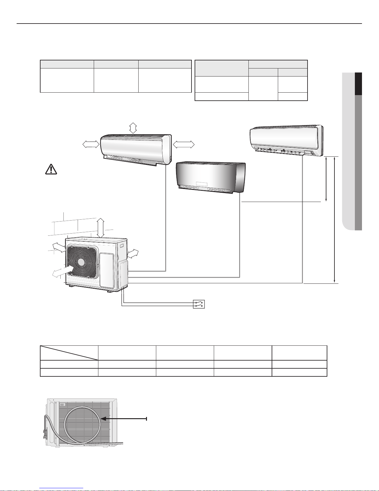
Outdoor Unit
5
ENGLISH
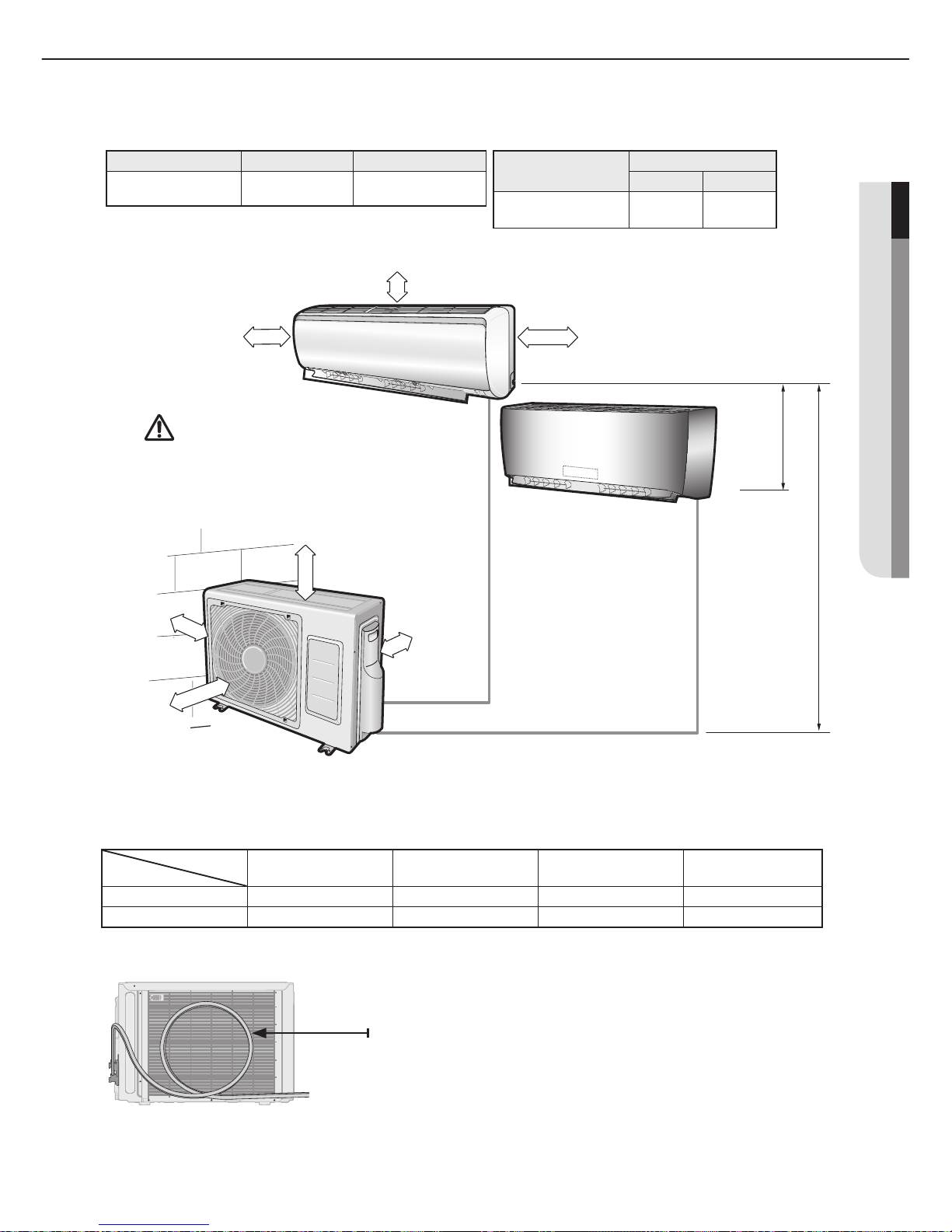
◆ RJ040F2HX
**
◆ Piping length and the helght
◆ Piping outside diameter
※ The appearance of the unit may be different from the diagram depending on the model.
※ The appearance of the unit may be different from the diagram depending on the model.
200 mm
or more
160 mm
or more
100 mm
or more
A B
(h) (H)
600 mm
minimum
300 mm
minimum
300 mm
minimum
600 mm
minimum
Make at least one round:
It will reduce noise and vibration
Indoor unit Outdoor unit Power supply 0, V, Hz
**
020/023/026/035
07/09/12
**
RJ040F2HX
**
1,220-240,50/60
Unit
Outside diameter
Liquid
Gas
**
020/023/026/035
07/09/12
**
1/4" 3/8"
※ RJ040F2HX** Outdoor unit cannot be connected to the following indoor unit combination.
- **052**/MH
***FM*
A/NJ
***
LHXEA/**18**/**24
**
1 Room max
length
2 Room total max
length
Max height between
indoor unit & outdoor unit
Max height between
indoor units
Dimension 20m 30m 15m 7.5m
Composition A,B A+B (H) (h)
CAUTION
3 m as minimum pipe length: It will reduce noise and
vibration.
6
A
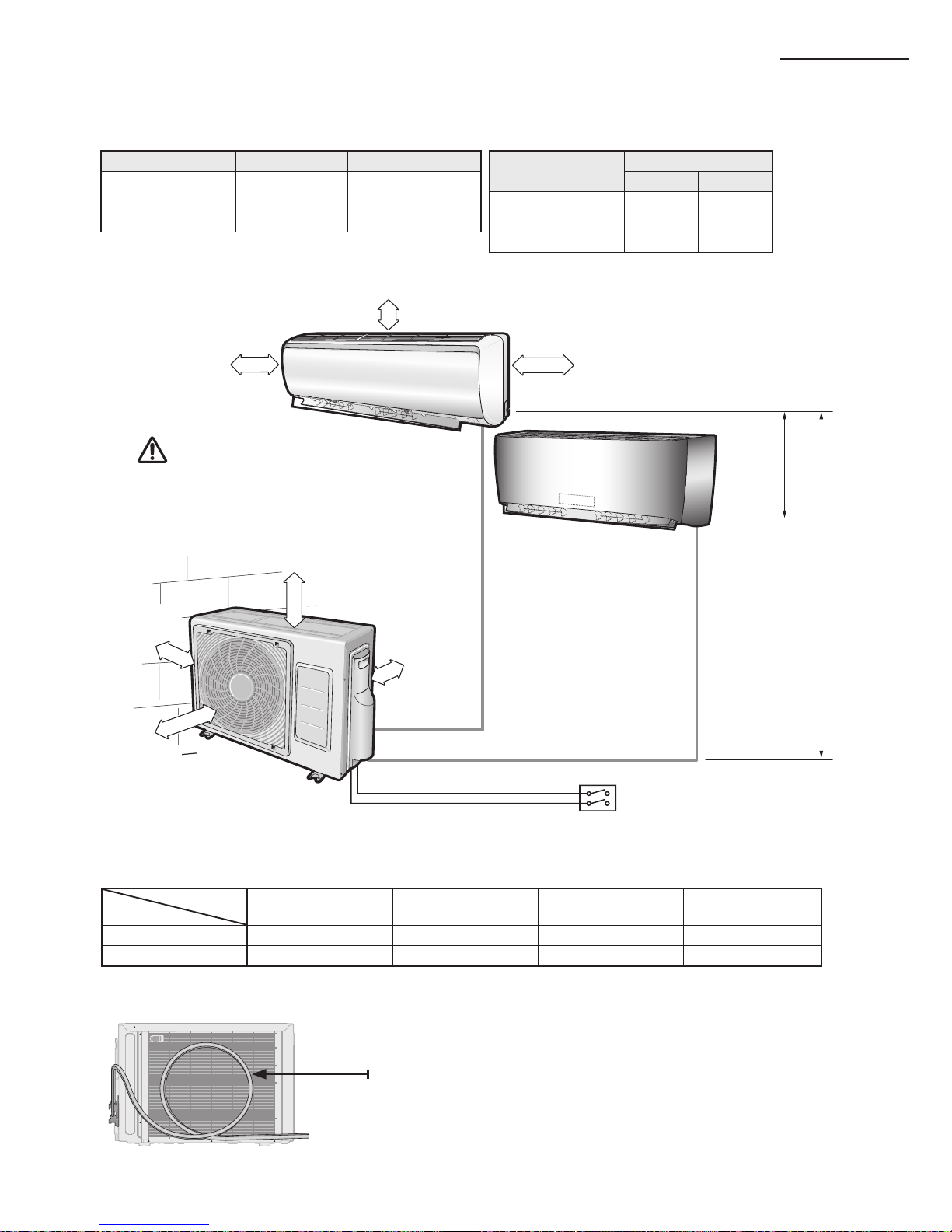
◆ RJ050F2HX
**
◆ Piping length and the helght
◆ Piping outside diameter
※ The appearance of the unit may be different from the diagram depending on the model.
※ The appearance of the unit may be different from the diagram depending on the model.
200 mm
or more
160 mm
or more
Main power switch
100 mm
or more
A B
(h) (H)
300 mm
minimum
300 mm
minimum
600 mm
minimum
CAUTION
3 m as minimum pipe length: It will reduce noise and
vibration.
Make at least one round:
It will reduce noise and vibration
Indoor unit Outdoor unit Power supply 0, V, Hz
**
020/023/026/
035/052
07/09/12/18
**
RJ050F2HX
**
1,220-240,50/60
Unit
Outside diameter
Liquid Gas
**
020/023/026/
030/035/07/09/12
**
1/4"
3/8"
**
052/18
**
1/2"
※ RJ050F2HX** Outdoor unit cannot be connected to the following indoor unit combination.
- MH052FMEA/MH052FUEA
1 Room max
length
2 Room total max
length
Max height between
indoor unit & outdoor unit
Max height between
indoor units
Dimension 20m 30m 15m 7.5m
Composition A,B A+B (H) (h)
Deciding on Where to Install the Air Conditioner
600 mm
minimum
7
ENGLISH
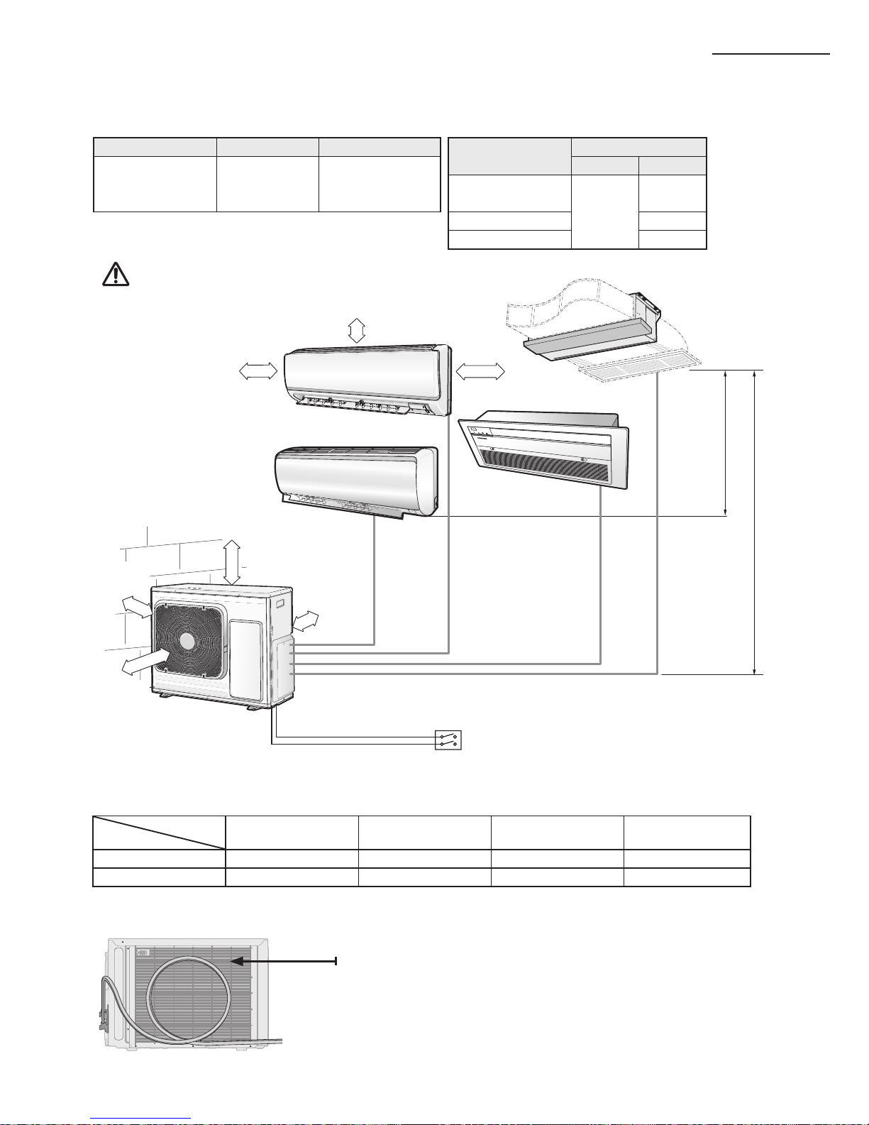
◆ RJ060F3HX
**
◆ Piping length and the helght
◆ Piping outside diameter
※ The appearance of the unit may be different from the diagram depending on the model.
※ The appearance of the unit may be different from the diagram depending on the model.
200 mm or more
160 mm or more
Main power switch
100 mm
or more
A
B C
(h)
(H)
600 mm
minimum
300 mm
minimum
300 mm
minimum
600 mm
minimum
Make at least one round:
It will reduce noise and vibration
Indoor unit Outdoor unit Power supply 0, V, Hz
**
020/023/026/
030/035/052
07/09/12/18
**
RJ060F3HX
**
1,220-240,50/60
Unit
Outside diameter
Liquid Gas
**
020/023/026/
030/035/07/09/12
**
1/4"
3/8"
**
052/18
**
1/2"
1 Room max
length
3 Room total max
length
Max height between
indoor unit & outdoor unit
Max height between
indoor units
Dimension 20m 45m 15m 7.5m
Composition A,B,C A+B+C (H) (h)
CAUTION
3 m as minimum pipe length: It will reduce noise and
vibration.
8
A
◆ RJ070/080F4HX
**
◆ Piping length and the helght
◆ Piping outside diameter
※ The appearance of the unit may be different from the diagram depending on the model.
※ The appearance of the unit may be different from the diagram depending on the model.
200 mm
or more
160 mm or more
Main power switch
100 mm
or more
A
CB
D
(h) (H)
600 mm
minimum
300 mm
minimum
300 mm
minimum
600 mm
minimum
CAUTION
3 m as minimum pipe length: It will reduce noise and
vibration.
Make at least one round:
It will reduce noise and vibration
Indoor unit Outdoor unit Power supply 0, V, Hz
**
020/023/026/
030/035/052/
07/09/12/18/24
**
RJ070F4HX
**
RJ080F4HX
**
1,220-240,50/60
Unit
Outside diameter
Liquid Gas
**
020/023/026/
030/035/07/09/12
**
1/4"
3/8"
**
052/18
**
1/2"
**24**
5/8"
1 Room max
length
4 Room total max
length
Max height between
indoor unit & outdoor unit
Max height between
indoor units
Dimension 25m 70m 15m 7.5m
Composition A, B,C,D A+B+C+D (H) (h)
Deciding on Where to Install the Air Conditioner
※**24** model is connectable to only an 8Kw
outdoor unit.
9
ENGLISH
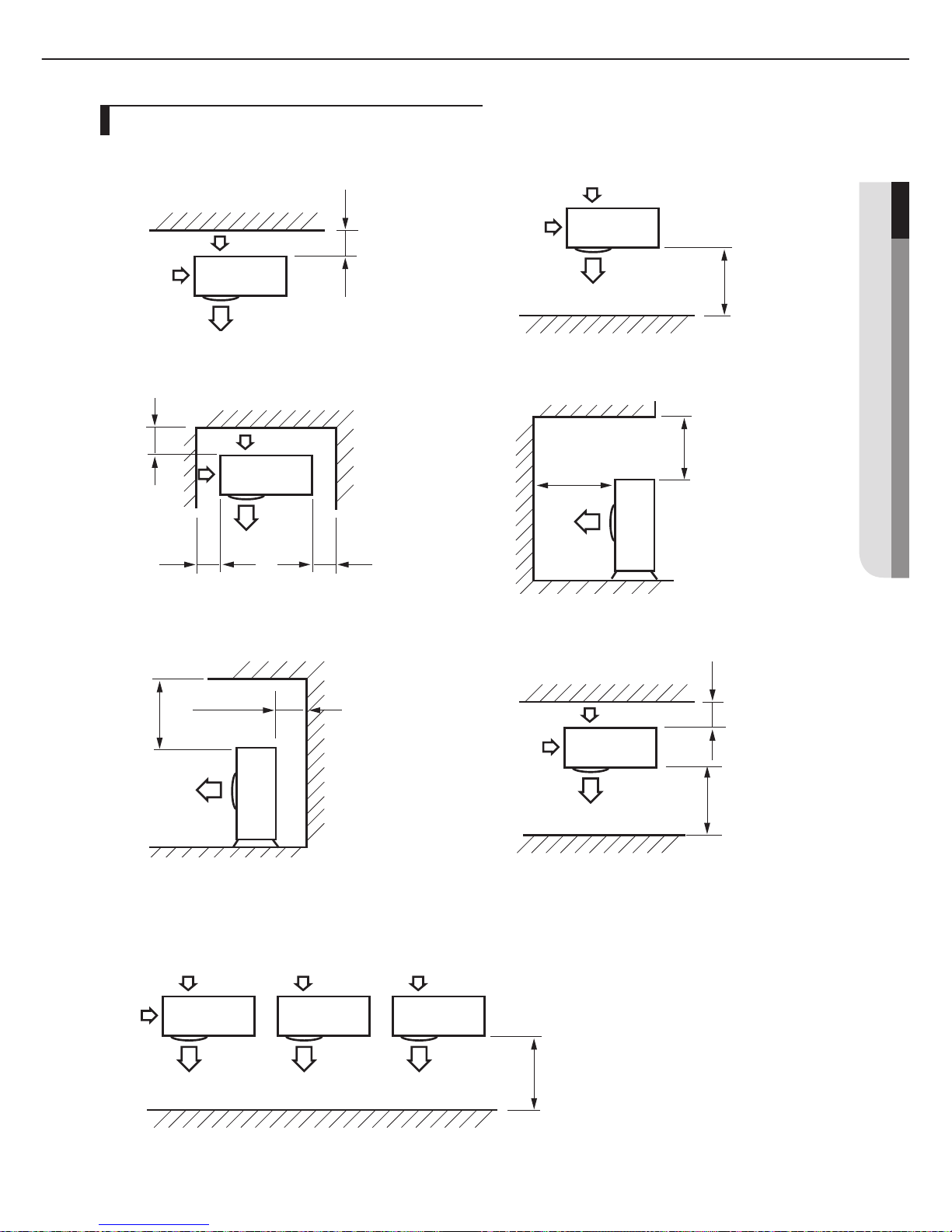
Space Requirements for Outdoor Uni
t
When installing 1 outdoor unit
300 or more
※ When the air outlet is opposite the wall
1500 or more
※ When the air outlet is towards the wall
300 or more
300 or more
600 or more
※ When 3 sides of the outdoor unit are blocked
by the wall
1500 or more
2000 or more
※ The upper part of the outdoor unit and the air
outlet is towards the wall
1500 or more
600 or more
300 or more
※ The upper part of the outdoor unit and the
air outlet is opposite the wall
300 or more
※ When front and rear side of the outdoor unit is
towards the wall
(Unit : mm)
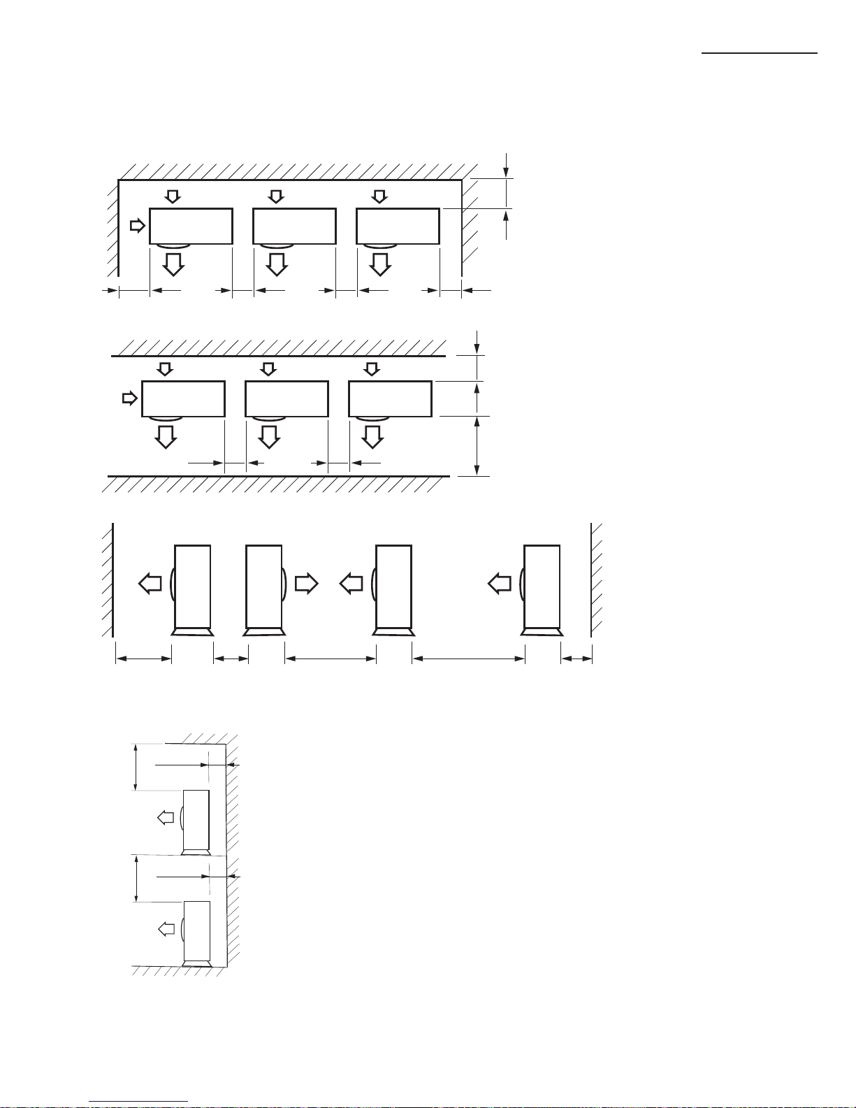
When installing more than 1 outdoor unit
(Unit : mm)
※ When the air outlet is towards the wall
1500 or more
10
A
300 or more
300 or more
1500 or more 600 or more 3000 or more
300 or more
3000 or more
600 or more 600 or more
300 or more1500 or more
600 or more 600 or more
600 or more
※ When 3 sides of the outdoor unit are blocked by the wall
※ When front and rear side of the outdoor unit is towards the wall
※ When front and rear side of the outdoor unit is towards the wall
When installing more than 1 outdoor unit
(Unit : mm)
※ The upper part of the outdoor unit and the air outlet is opposite the wall
300 or more
300 or more
500 or more
500 or more
Deciding on Where to Install the Air Conditioner
11
A
ENGLISH
Air conditioner and accessories
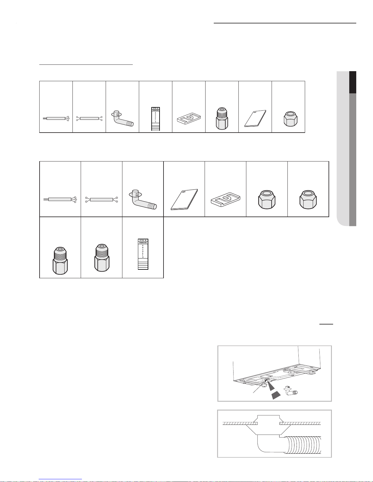
The following accessories are supplied with the air conditioner.
Accessories in the Outdoor Unit Case
◆ RJ040F2HX**/RJ050F2HX**/RJ060F3HX
**
※ Attach Energy Label to the outdoor unit properly when installing.
◆ RJ070F4HX**/RJ080F4HX
**
※ Attach Energy Label to the outdoor unit properly when installing.
≫
The 3-wire power cable and the 2-wire assembly cable are optional. If these cables are not supplied,
use the standard cable approved by IEC standard.
Please, check “Connecting the Cables to the Outdoor Unit” section.
3-wire
Power Cable
(option)
2-wire
Assembly Cable
(option)
Drain Plug
Installation
Manual
Rubber Leg
Flare Nuts, 15.88mm
outer pipe diameter
(RJ080F4HX**)
Flare Nuts, 9.52mm
outer pipe diameter
Flare Bolt
(Nut
12.70mm;Bolt
9.52mm)
Flare Bolt
(Nut 12.70mm;
Bolt 15.88mm)
(RJ080F4HX**)
Energy Label
While heating, ice may accumulate. During the process of
defrosting, check if condensation draining is adequate. For
adequate draining, do the following:
1.
Insert the drain plug into the drain hole on the
underside of the outdoor unit.
2.
Connect the drain hose to the drain plug.
3. Ensure that condensation draining is adequate.
Drain hole
Drain hole
Installing and connecting the drain hose of the outdoor unit
3-wire
Power Cable
(option)
2-wire
Assembly Cable
(option)
Drain Plug Energy Label Rubber Leg
Flare Bolt
(Nut 12.70mm;Bolt
9.52mm) (except
RJ040F2HX**)
Installation
Manual
Flare Nuts, 9.52mm
outer pipe diameter
(except RJ040F2HX**)
12
A
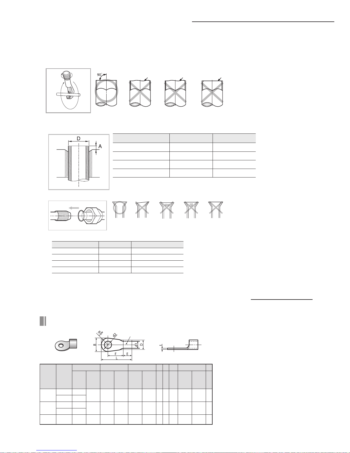
Cutting/extending the piping
1. Make sure that you have the required tools available (pipe cutter, reamer,aring tool and pipe holder).
2. If you wish to shorten the piping, cut it using a pipe cutter, taking care toensure that the cut edge remains at a 90° angle with the side of
the pipe,and referring to the illustrations below for examples of edges cut correctlyand incorrectly.
3. To prevent any gas from leaking out, remove all burrs at the cut end of thepipe, using a reamer.
4. Slide a are nut on to the pipe and modify the are.
5. Check that the flaring is correct, referring to the illustrations below for examples of incorrect flaring.
6. Align the pipes to be connected and tighten the are nuts rst manually andthen with a torque wrench, applying the following torque.
7. For further details on how to connect up to the outdoor unit and purge the circuit, refer to page 19.
Oblique Rough Burr
Outer Diameter (D) Thickness Depth (A)
ø6.35 mm(1/4") 0.8mm 1.3 mm
ø9.52 mm(3/8") 0.8mm 1.8 mm
ø12.70 mm(1/2") 0.8mm 2.0 mm
ø15.88 mm(5/8") 0.8mm 2.2 mm
Uneven
Thickness
CrackedDamaged
Surface
InclinedCorrect
≫
In case welding the pipe, the gas nitrogen must be blown into the parts.
Connecting the cables to the outdoor unit
Outer Diameter (D) Thickness Torque (kgf·cm)
ø6.35 mm(1/4") 0.8mm 140~170
ø9.52 mm(3/8") 0.8mm 250~280
ø12.70 mm(1/2") 0.8mm 380~420
ø15.88 mm(5/8") 0.8mm 440~480
Silver solder
Selecting compressed ring terminal
Norminal
dimensions
for cable
(mm
2
)
Norminal
dimensions
for screw
(mm
)
B D d1 E F L d2 t
Standard
dimension
(mm)
Allowance
(mm)
Standard
dimension
(mm)
Allowance
(mm)
Standard
dimension
(mm)
Allowance
(mm)
Min. Min. Max.
Standard
dimension
(mm)
Allowance
(mm)
Min.
1.5
4 6.6
±0.2 3.4
+0.3
-0.2
1.7 ±0.2 4.1 6 16 4.3
+0.2
0
0.7
4 8
2.5
4 6.6
±0.2 4.2
+0.3
-0.2
2.3 ±0.2 6 6 17.5 4.3
+0.2
0
0.8
4 8.5
4 4 9.5 ±0.2 5.6
+0.3
-0.2
3.4 ±0.2 6 5 20 4.3
+0.2
0
0.9
 Loading...