

Samsung RHF025EE Series, RHF050EE Series, RHF080EE Series, RHF035EE Series, RHF100EE Series Installation Manual
ENGLISH
ERV
(Energy Recovery Ventilator)
INSTALLATION
MANUAL
RHF025EE Series
RHF035EE Series
RHF050EE Series
RHF080EE Series
RHF100EE Series
ESPAÑOLFRANÇAISITALIANOPORTUGUÊSDEUTSCH
DB98-27512A(1)SE F I P D

E-2
Contents
PREPARATION
Safety Precautions ......................................................................................................... 3
Space Requirements .................................................................................................... 5
Installation Diagram ..................................................................................................... 7
External Dimension ...................................................................................................... 8
INSTALLING THE UNIT
Installing the Unit .......................................................................................................... 10
Electric Wiring ................................................................................................................. 11
Schematic Diagram ...................................................................................................... 14
Option Switches ............................................................................................................. 15
Connecting the Unit ..................................................................................................... 16
COPMPLETING THE INSTALLATION
Duct Connection ........................................................................................................... 26
Performance Graph ...................................................................................................... 27
Final Checks and Trial Operation ............................................................................ 29
E-3
ENGLISH
WARNING
This indicates the possibility of serious injury or death.
Do not install the unit
by yourself. Incorrect
installation of the unit could
cause injury due to fire,
electric shock and water
leakage or from the unit
falling. Consult a dealer or
a qualified installer.
Hang down a blockage for
bird in front of outdoor air
suction duct. If something
such as bird’s nest blocks
the air suction duct, it may
result in oxygen shortage in
indoors.
Perform the installation
securely referring to the
installation manual.
Incomplete installation
could cause personal injury
due to fire, electric shock or
the unit falling.
Do not attempt to repair,
move, modify or reinstall
the unit on your own. Make
sure that these installations
are carried out by qualified
personnel to avoid electric
shock or fire.
Check if the voltage and
the frequency of the main
power supply are required
for the unit to be installed
and check the connection.
The electric work must be
done by service agent or
similarly qualified person
according to national wiring
regulations and use only
rated cable. If the capacity
of the electric work is not
properly completed, electric
shock or fire may occur.
Make sure the air intake is
located far from an exhaust
port of a burner. It may
cause oxygen shortage.
Ground the unit. Do not
connect the ground to a gas
pipe, water pipe, lighting
rod or telephone grounding.
Defective grounding could
cause electric shock.
Install the cables with
supplied cables firmly.
Fix them securely so that
external force is not to exert
to the terminal board.
If the connection or fixing is
incomplete, heat generation,
electric shock or fire may
occur.
Install separate MCCB and
ELB when installing the
power cable. If you do not
install the MCCB and ELB,
electric shock or fire may
occur.
If the power plug is
damaged, replace it by the
manufacturer or qualified
personnel to avoid the risk.
Disconnect the circuit
breaker when you don’t use
the product for a long period
of time to save energy.
Do not install the electric
wire to get tension to avoid
a hazard.
Unplug the product before
get repaired.
Do not pull the electric wire
or touch the power plug
with wet hands.
Installers are required to
read the general information
carefully for safety.
Do not put the product near
dangerous substances to
prevent fire, explosion or
injury and do not expose the
product to direct
sunlight.
Safety Precautions
Keep this installation manual together with the user’s manual in a handy place so that you can find it whenever
you need to see it after reading this manual thoroughly.
Make sure to read the following safety precautions carefully before installation.
Make sure to observe the cautions specified in this manual.
Conduct a test run of the unit after installation and then explain all system functions to the owner.
The indications and meanings are as shown below.
E-4
CAUTION
This indicates the possibility of serious injury or damage to environments when
operated incorrectly.
Install the unit in a place
where it is strong enough to
hold the product weight.
When installed in place
where it is not strong
enough to withhold the
product weight, the unit
may fall and cause injury.
Install the product inside
heat insulation over the
ceiling not to be contacted
with the outside air.
If the product is installed
out of the insulation, it may
result in electric shock or
malfunction due to moisture
generated in the product.
Do not install the product
in a place where it is
exposed to inflammable gas
leakage.
Do not install the product
in humid place such as
bathroom. It may cause
electric shock or malfunction.
Make sure to use the part
provided or specified parts
for the installation work. The
use of defective parts could
cause injury, fire, electric
shock or the unit falling, etc.
Do not install the product
in the place where exposed
to sulfurous acid or steam
because it may damage the
parts or cause malfunction.
Do not install the product in
the place where generates
toxic gas such as chemical
factory. It may cause fire or
gas poisoning.
Check the product for
damage that may have
taken place during
transportation and do not
install or use damaged
equipment.
All of the manufacturing and
packaging material used for
your new appliance are
compatible with the
environment and can be
recycled.
Dispose of the packaging
material in accordance with
the local requirements.
Install a ground leakage
breaker depending on the
installation place (where it is
humid). If not, it may cause
electric shock.
The product must be
installed according to the
national electrical
regulations.
The maximum input
power and current is
measured according to the
IEC Standard and the input
power and current is
measured according to
ISO standard.
WARNING
This indicates the possibility of serious injury or death.
Avoid the use of an
extension cord and do not
share the power outlet
with other appliances.
Incomplete connection,
defective insulation or
exceeding the permissible
current may cause electric
shock or fire.
Make sure to turn off the
main power when setting up
the product’s electric circuit
or power cords. There is
electric shock.
The product should be
installed in accordance with
the National Electrical
regulations.
Ensure that the national
safety code requirements
have been followed for the
main supply circuit. Ensure
that a properly sized and
connected ground wire is in
place.
E-5
ENGLISH
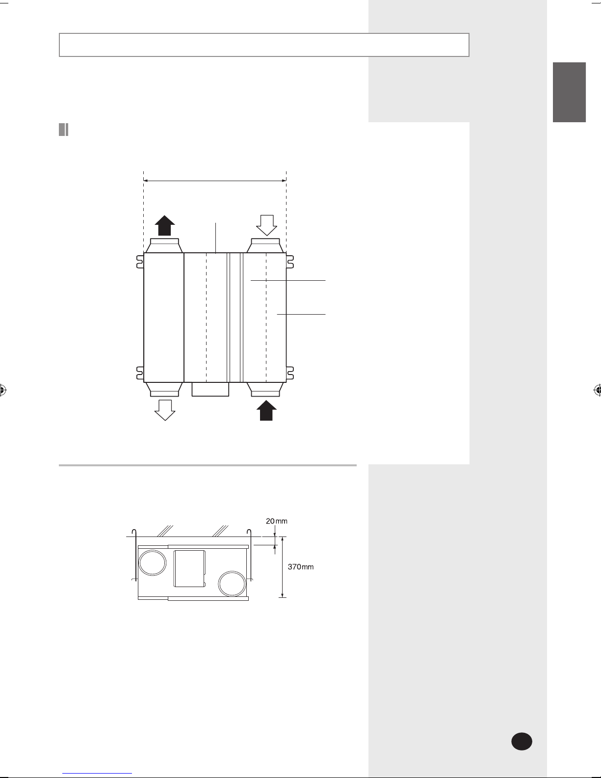
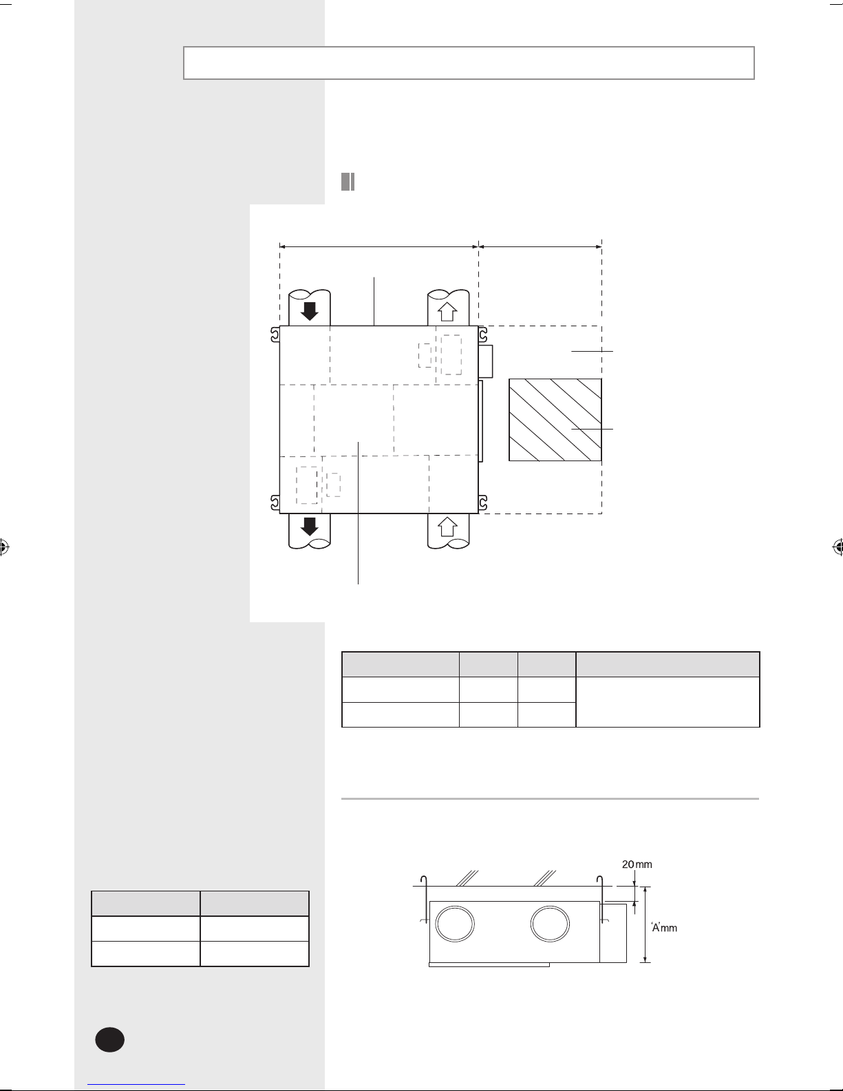
Space Requirements
The ventilator should be installed in a ceiling which has enough space
above as seen in the picture.
Exhaust Air
Supply Air
Outdoor Air
Heat exchange element
Body
Inspection hole
(for filter, heat exchange element,
fan, motor and damper)
Return Air
600mm
025
E-6
Space Requirements (Continued)
Body
Space for repairing
Exhaust Air
Supply Air
Outdoor Air
Heat exchange element
Inspection hole
(for filter, heat exchange element,
fan, motor and damper)
Return Air
The ventilator should be installed in a ceiling which has enough space
above as seen in the picture.
Model 'A' 'B' Number of heat exchange elements
035/050
1000 600
2
080/100
1135 800
Model 'A'
035/050
320
080/100
440
035/050/080/100
'A'mm 'B'mm
E-7
ENGLISH
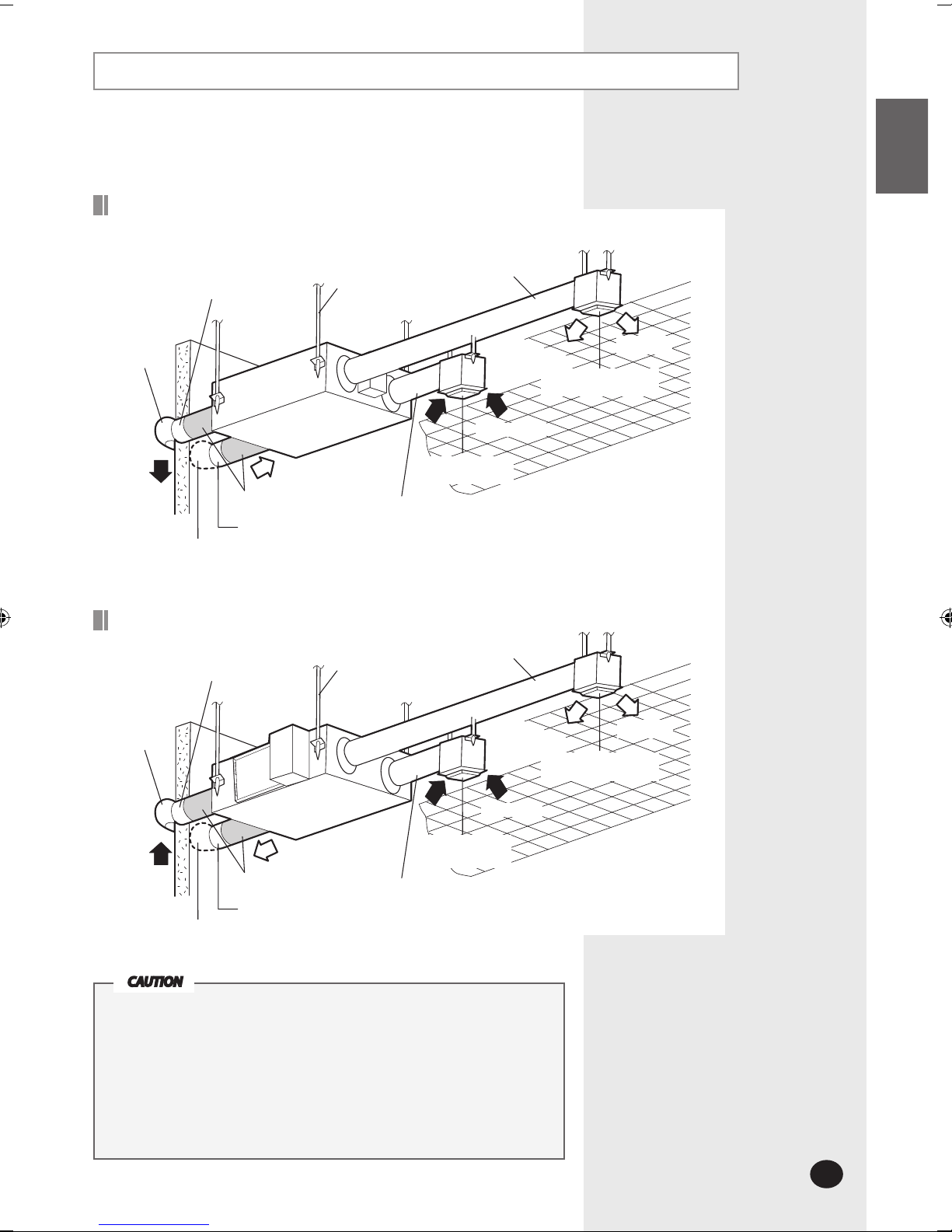
Installation Diagram
Supply Air
Exhaust Air duct
Hood
Anchor bolt
Insulation
Outdoor Air suction duct
Hood
Exhaust Air
Return Air duct
Air intake hole
(Air exhaust grille)
Return Air
Air discharging hole
(Air exhaust grille)
Supply Air duct
Supply Air
Exhaust Air duct
Hood
Anchor bolt
Insulation
Outdoor Air suction duct
Hood
Outdoor Air
Return Air duct
Air intake hole
(Air exhaust grille)
Return Air
Air discharging hole
(Air exhaust grille)
Supply Air duct
025
035/050/080/100
Install the unit in a place where it is strong enough to hold the product
weight.
Install the unit in a place where the space is enough to install or repair
the unit.
Do not install the unit in humid place such as bathroom.
Do not install the unit in a place over 40°C or where exposed to fire,
gasoline or smoke directly.
Install the cables with supplied ones securely.
CAUTION
E-8
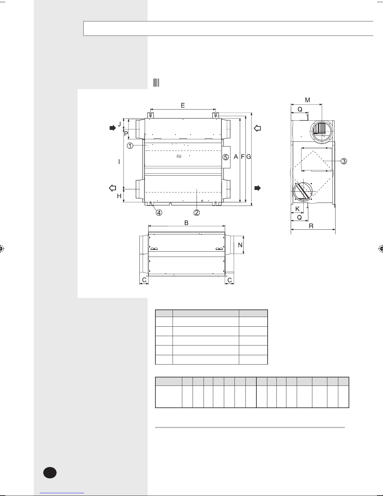
External Dimension
No. Name Quantity
Maintenence cover 1
Heat exchange element 1
Dust filter 2
Hanger 4
Electrical component box 1
Nominal diameter for duct : Ø150mm
(Unit : mm)
Model A B C E F G H I J K M N P Q R
025
600 660 70 510 675 729 102 470 85 98 242Ø140Ø156 133 350
Exhaust Air Supply Air
Outdoor Air Return Air
Ensure the space for installing and repairing.
025

E-9
ENGLISH
No. Name Quantity
Maintenence cover 1
Heat exchange element 2
Dust filter 4
Hanger 4
Electrical component box 1
Exhaust Air
Outdoor Air
Return Air
Supply Air
Model A B C E F G H I J K M N P
035/050
1000 1012 99 940.6 1036.4 26 130 617 253 135 270 Ø194 Ø241.5
080/100
1135 1220 84 1110 1183 25 184 613.25 387.75 170 340 Ø244 Ø270
(Unit : mm)
Ensure the space for installing and repairing.
035/050/080/100
Model
Nominal diameter for duct
035/050
Ø
200
080/100
Ø
250
(Unit : mm)
 Loading...