

Samsung RF267AARS, RF26DBRS1, RF267AAWP, RF26DBSH1, RF267AASH Service Manual
...
BOTTOM MOUNT FREEZER
BASIC : RF267AA
MODEL NAME : RF267AARS RF26DBRS1
RF267AABP RF26DBBP1
RF267AAWP RF26DBSH1
RF267AASH
MODEL CODE : RF267AARS/XAA RF26DBRS1/SML
RF267AABP/XAA RF26DBBP1/SML
RF267AAWP/XAA RF26DBSH1/SML
RF267AASH/XAA RF26DBRS1/XSA
REFRIGERATOR
REFRIGERATOR CONTENTS
1. PRECAUTIONS(SAFETY WARNINGS) 4
2. PRODUCT SPECIFICATIONS
7
3. DISASSEMBLY AND REASSEMBLY
21
4. TROUBLESHOOTING
47
5 . EXPLODED VIEW & PARTS LIST
85
6. PCB DIAGRAM
123
7. WIRING DIAGRAM
128
8. SCHEMATIC DIAGRAM
129
Asia : http://asia.samsungportal.com)
RF267/26DB
For the latest parts information, Please access to our service web site
North America : http://service.samsungportal.com Europe : http://europe.samsungportal.com
(

IMPORTANT SAFETY NOTICE
The service guide is for service men with adequate backgrounds of
electrical, electronic, and mechanical experience. Any attempt to repair
a major appliance may result in personal injury and property damage.
The manufacturer or dealer cannot be responsible for the interpretation
of this information.
SAMSUNG ELECTRONICS AMERICA, INC.
Technical Service Guide
Copyright ⓒ2008
All rights reserved. This service guide may not be reproduced in whole or in
part in any form without written permission from the SAMSUNG ELECTRONICS
Company.
WARNING

Contents
1. PRECAUTIONS(SAFETY WARNINGS) 4
2. PRODUCT SPECIFICATIONS 7
2-1) INTRODUCTION OF MAIN FUNCTION 8
2-2) SPECIFICATIONS 11
2-3) INTERIOR VIEWS 12
2-4) MODEL SPECIFICATION 13
2-5) MODEL SPECIFICATION &SPECIFICATION CHART 14
2-6)DIMENSIONS OF REFRIGERATOR (INCHES) 17
2-7) OPTIONAL MATERIAL SPECIFICATION 18
2-8) REFRIGERANT ROUTE IN REFRIGERATION CYCLE 19
2-9) COOLING AIR CIRCULATION 20
3. DISASSEMBLY AND REASSEMBLY 21
3-1) PRECAUTION 22
3-2) REFRIGERATOR DOOR 23
3-3) DOOR SWITCH IN REFRIGERATOR 25
3-4) DOOR GASKET 25
3-5) DOOR HANDLE 25
3-6) REFRIGERATOR LIGHT 26
3-7) COVER-DISPLAY & WATER-DISPENSER 26
3-8) WATER-DISPENSER 27
3-9) GLASS SHELF 28
3-10) FOLDABLE GLASS SHELF 29
3-11) VEGETABLE & FRUIT DRAWERS SHELF 29
3-12) COOL SELECT PANTRY 30
3-13) WATER TANK 31
3-14) MOTOR DAMPER 33
3-15) WATER FILTER (DISASSEMBLY) 33
3-16) WATER FILTER (REASSEMBLY) 34
3-17) GALLON DOOR BIN 34
3-18) VERTICAL HINGED SECTION 35
3-19) EVAPORATOR COVER IN REFRIGERATOR 36
3-20) EVAPORATOR IN REFRIGERATOR 37
3-21) FREEZER DOOR 38
3-22) PULL OUT DRAWER 39
3-23) ICE-MAKER 40
3-24) FREEZER LIGHT 41
3-25) DOOR SWITCH IN FREEZER 41
3-26) EVAPORATOR COVER IN FREEZER 42
3-27) EVAPORATOR IN FREEZER 42
3-28) MACHINE COMPARTMENT 43
3-29) ELECTRIC BOX 46
4. TROUBLESHOOTING 47
4-1) FUNCTION FOR FAILURE DIAGNOSIS 48
4-1-1. TEST MODE (MANUAL OPERATION / MANUAL DEFROST FUNCTION)
48
4-1-2. DISPLAY FUNCTION OF COMMUNICATION ERROR
49
4-1-3. SELF-DIAGNOSTIC FUNCTION
50
4-1-4. DISPLAY FUNCTION OF LOAD CONDITION 53
4-1-5. EXHIBITION MODE SETTING FUNCTION 54
4-1-6. OPTION SETTING FUNCTION 54

Contents
4-1-7. OPTION TABLE 57
4-2) DIAGNOSTIC METHOD ACCORDING TO THE TROUBLE SYMPTOM(FLOW CHART) 59
4-2-1. IF THE TROUBLE IS DETECTED BY SELF-DIAGNOSIS 60
4-2-2. IF FAN DOES NOT OPERATE 70
4-2-3. IF ICE ROOM FAN DOES NOT OPERATE 71
4-2-4. IF ICE MAKER DOES NOT OPERATE 72
4-2-5. IF DEFROST DOES NOT OPERATE (F,R DEF HEATER) 73
4-2-6. IF POWER IS NOT SUPPLIED 74
4-2-7. IF COMPRESSOR DOES NOT OPERATE 75
4-2-8. WHEN ALARM SOUND CONTINUOUS WITHOUT STOP(RELATED WITH BUZZER SOUND) 76
4-2-9. IF PANEL PCB DOES NOT WORK NORMALLY 78
4-2-10. IF PANTRY PANEL PCB IS NOT WORKING NORMALLY 79
4-2-11. WHEN REFRIGERATOR ROOM LAMP DOES NOT LIGHT UP 80
4-2-12. IF ICE WATER IS NOT SUPPLIED 81
4-2-13. IF WATER IS NOT SUPPLIED 82
4-2-14. IF CUBED OR CRUSHED ICE IS NOT SUPPLIED 83
4-2-15. IF COVER ICE ROUTE MOOR(GEARD MOTOR) IS NOT WORKING NORMALLY 84
5 . EXPLODED VIEW & PARTS LIST 85
5-1) FREEZER 86
5-2) REFRIGERATOR 89
5-3) CABINET 93
5-4) DISASSEMBLY OF FREEZE DOOR 97
5-5) DISASSEMBLY OF REFRIGERATOR DOOR LEFT 99
5-6) DISASSEMBLY OF REFRIGERATOR DOOR RIGHT 102
6. PCB DIAGRAM 123
6-1) PCB LAYOUT WITH PART POSITION 124
6-2) PCB LAYOUT WITH PART POSITION (SMPS BOARD) 125
6-3) CONNECTOR LAYOUT WITH PART POSITION (MAIN BOARD) 126
6-4) CONNECTOR LAYOUT WITH PART POSITION (SMPS OARD) 127
7. WIRING DIAGRAM 128
8. SCHEMATIC DIAGRAM 129
8-1) WHOLE BLOCK DIAGRAM 129
8-2) CIRCUIT DIAGRAM 130

4
1. PRECAUTIONS(SAFETY WARNINGS)
●
Pull the power plug out before for the change or repair of electric parts.
→
Be careful the electric shock.
●
When exchanging the parts, use the correct parts.
→
Check the model name, rating voltage, rating current, running
temperature symbols.
●
When troubleshooting, connect firmly the types of harness.
→
Make not to be separated when some power is imposed.
●
Check the traces of water infiltration at the electric parts.
→
If there is a trace of water infiltration, exchange or tape the parts.
●
Check the assemble status of parts after troubleshooting.
→
It should be done indiscriminately as before the repair.
●
Check the use circumstance of refrigerator.
→
If the refrigerator is installed at the place that is damp or wet, or
status of installation is unstable, change the installation place.
●
Do earth in case of need.
→
Particularly, Be sure to earth when there is a risk of an electric
leakage by humidity or wetness.
●
Do not use multi plugs in a plug socket at the same time.
Check if the power cord and socket is damaged, pressed, squeezed,
or fired.
→
If the plug or plug socket is damaged, repair or exchange that
immediately.
●
Do not allow consumers to repair the appliance by themselves.
●
Do not store other materials except the foods.
→
Drugs or scientific materials : difficult to keep precise temperature.
→
The inflammables(alcohol, benzene, ether, LP gas, butane gas etc.):
have risk of explosion.
5
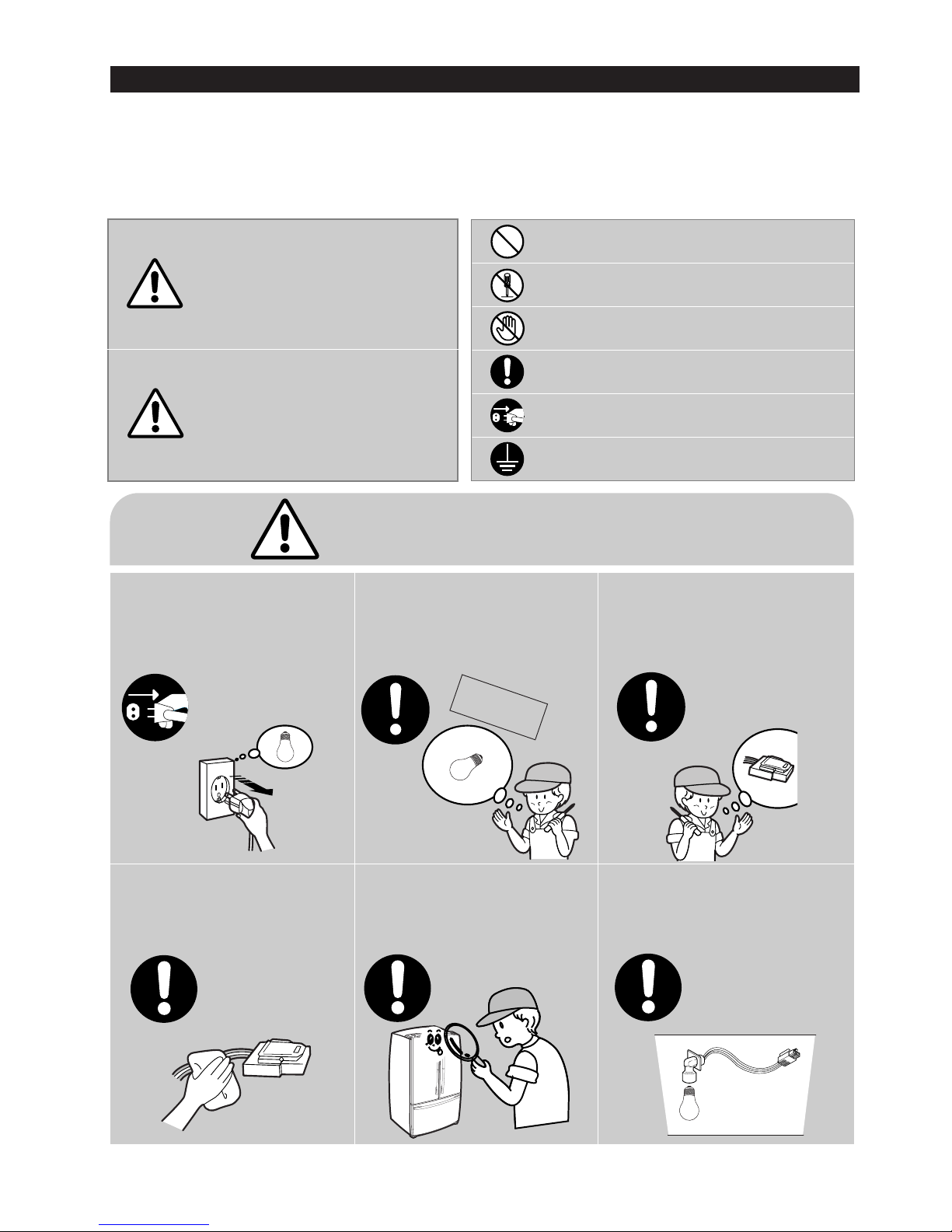
PRECAUTIONS(SAFETY WARNINGS)
Read all instructions before repairing the product and follow the instructions
in order to prevent danger or property damage.
CAUTION/WARNING SYMBOLS DISPLAYED
SYMBOLS
Indicates that a
danger of death
or serious injury
exists.
Indicates that a risk
of personal injury
or material damage
exists.
means “Prohibited”.
means “Do not disassemble”.
means “No contact”.
means ”Warning or Caution”.
means “Earth or Ground”.
means “Unplug the unit before
preforming service”
Pull the power plug out to
exchange the interior lamp
of the refrigerator.
●
It may cause electric shock.
Warning
Warning & Caution
Caution
Unplug
Use the rated components
on the replacement.
●
Check the correct model, rated
voltage, rated current, operating
temperature and so on.
On repair, make sure that the
wires such as harness are
bundled tightly.
●
Bundle tightly wires in order not to be
detached by the external force and then not
to be wetted.
Check if there is any trace
indicating the permeation
of water.
●
If there is that kind of trace, change
the related components or do the
necessary treatment
such as taping
using the
insulating tape.
After repair, check the
assembled state of components.
●
It must be in the same assembled state
when compared with the state before
disassembly.
On repair, remove completely dust
or other things of housing parts,
harness parts, and check parts.
●
Cleaning may prevent the possible fire by
tracking or short.
Rated
components
6
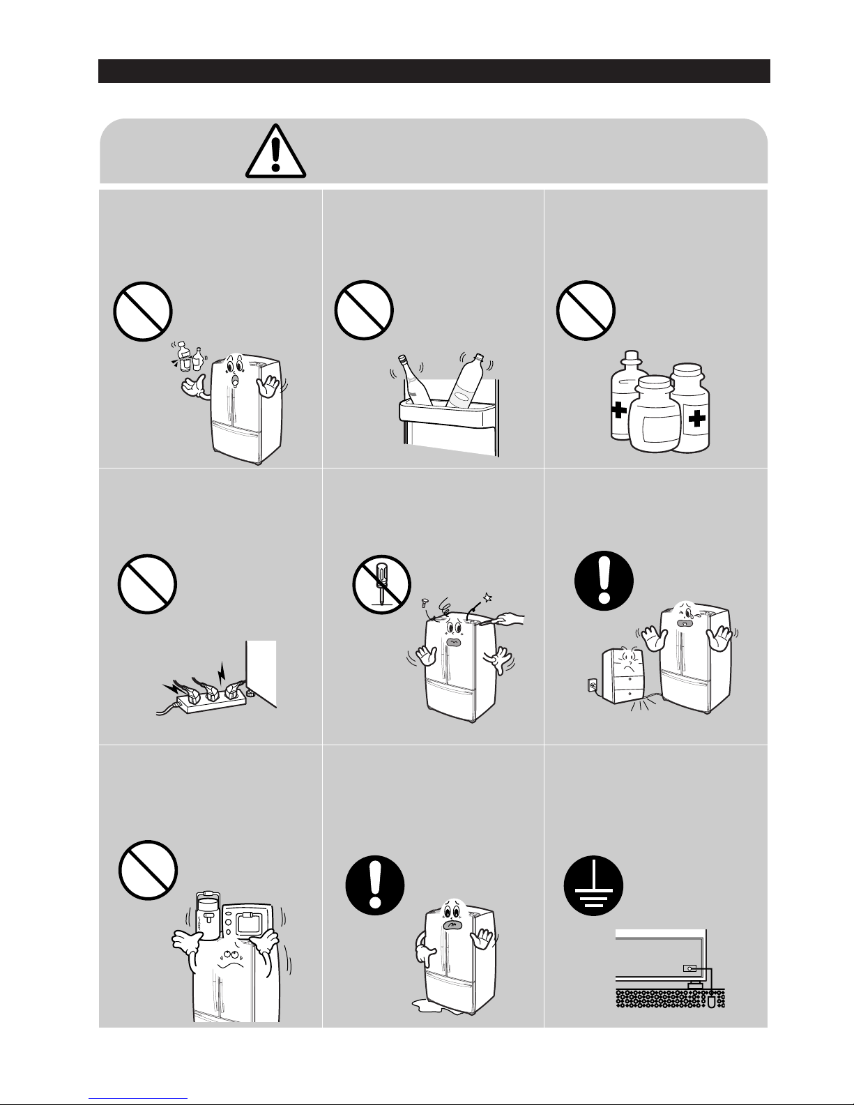
PRECAUTIONS(SAFETY WARNINGS)
❈
Please let users know following warnings & cautions in detail.
Do not allow users to put bottles or
kinds of glass in the freezer.
●
Freezing of the contents may inflict a wound.
Do not allow users to store narrow
and lengthy bottles or foods in a
small multi-purpose room.
●
It may hurt you when refrigerator door is
opened and closed resulting in falling stuff
down.
Do not allow users to store
pharmaceutical products, scientific
materials, etc., in the refrigerator.
●
The products which temperature control
should not be stored in the refrigerator.
Do not allow users to store
articles on the product.
●
Opening or closing the door may cause
things to fall down, which may cause
injury.
Prohibition
Warning & Caution
Do not allow users to
disassemble, repair or alter.
●
It may cause fire or abnormal
operation which leads to injury.
Do not
disassemble
Do not allow users to insert the
power plugs for many products
at the same time.
●
May cause abnormal generation of
heat or fire.
Prohibition
Do not allow users to bend the
power cord with excessive force
or do not have the power cord
pressed by heavy article.
●
May cause fire.
Do not allow users to install the
refrigerator in the wet place or
the place where water splashes.
●
Deterioration of insulation of electric
parts may cause electric shock or fire.
Make sure of the earth.
●
Be sure the product is properly grounded.
Earth

7
2. PRODUCT SPECIFICATIONS
2-1) INTRODUCTION OF MAIN FUNCTION 8
2-2) SPECIFICATIONS 11
2-3) INTERIOR VIEWS 12
2-4) MODEL SPECIFICATION 13
2-5) MODEL SPECIFICATION &SPECIFICATION CHART 14
2-6)DIMENSIONS OF REFRIGERATOR (INCHES) 17
2-7) OPTIONAL MATERIAL SPECIFICATION 18
2-8) REFRIGERANT ROUTE IN REFRIGERATION CYCLE 19
2-9) COOLING AIR CIRCULATION 20
8
2. PRODUCT SPECIFICATIONS
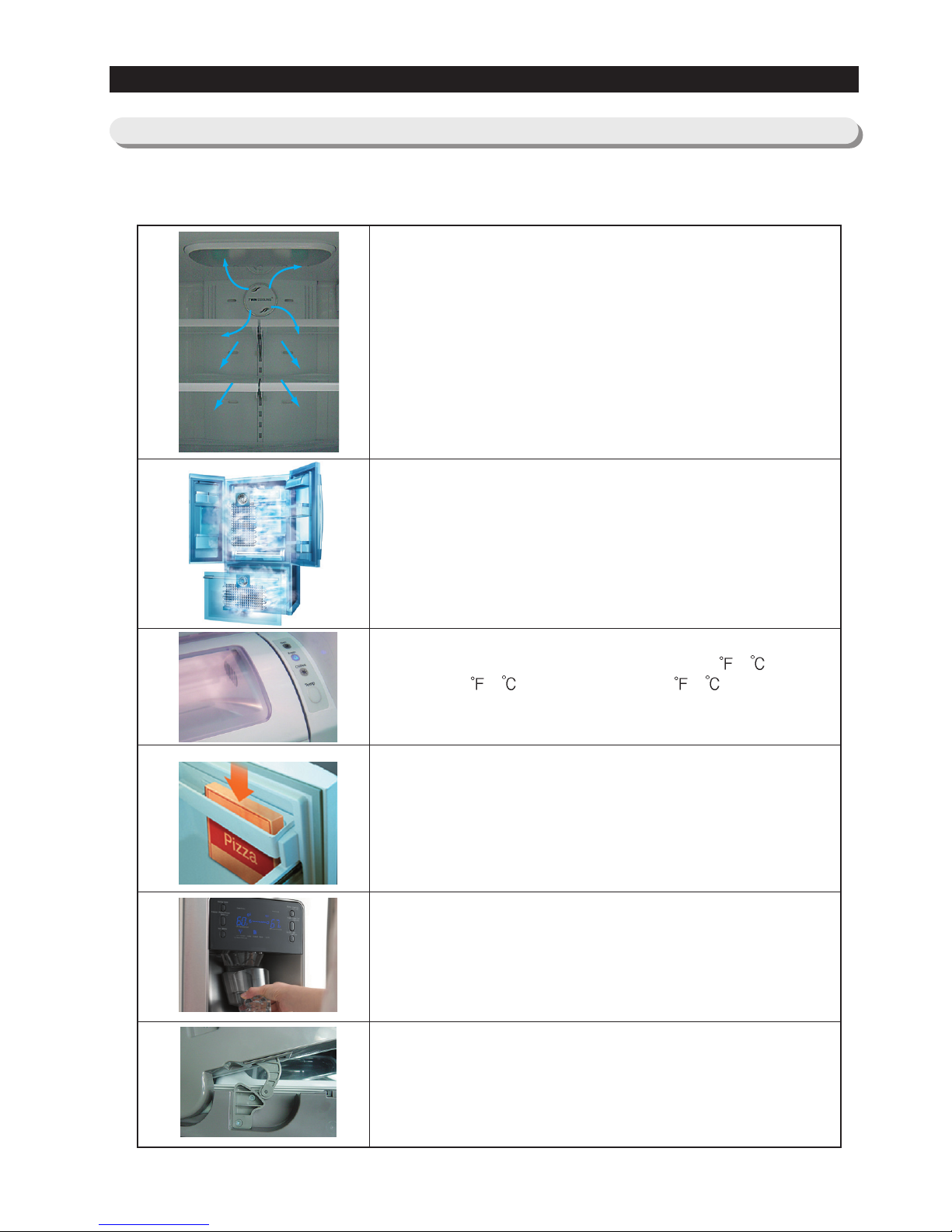
●●
A newly Developed SAMSUNG bottom mount freezer in 2008 has the following
characteristics.
Surround Multi Flow
●●
Uniform cooling for each shelf and even in corner in fresh
food compartment by centerpositioned fan and duct with
multiple flow effluences
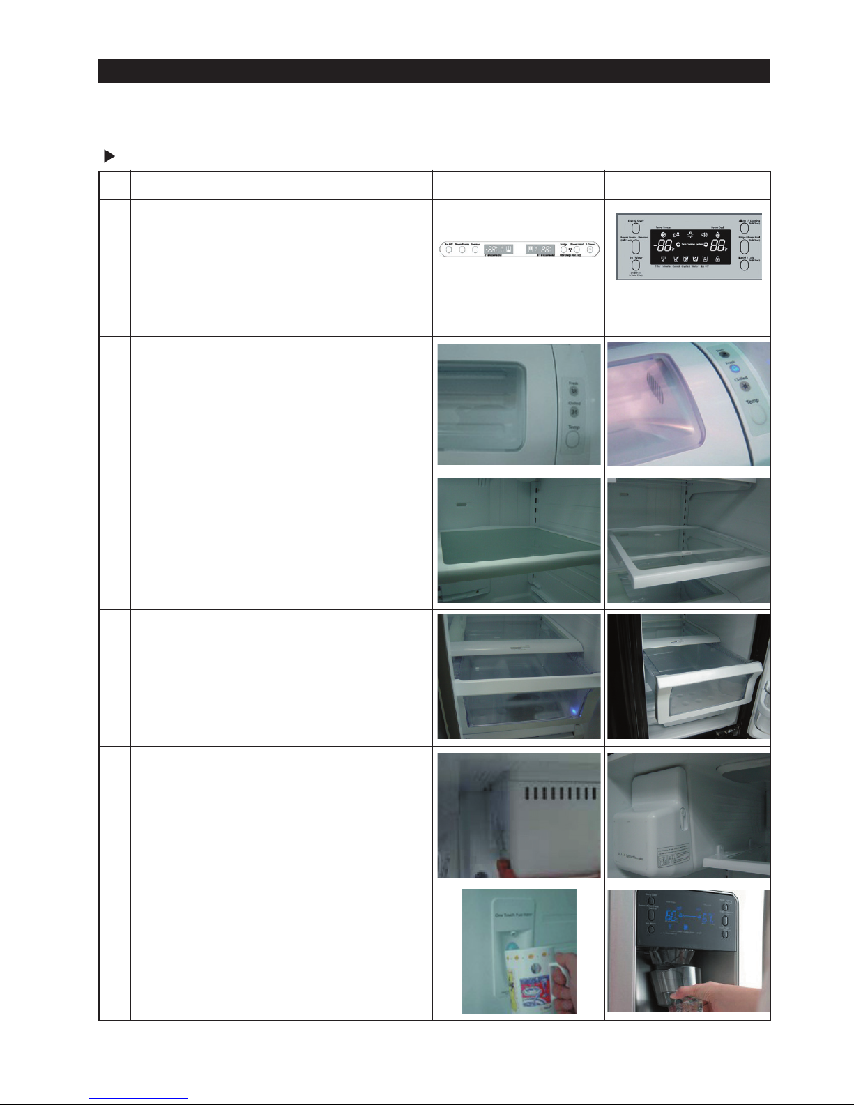
Twin Cooling System
●●
The refrigerator and the freezer have two evaporators.
Given this independent system, the freezer and the
refrigerator are cooled individually as required and are,
therefore, more efficient.
Food odor from the refrigerator does not affect food in the
freezer due to separate air flow circulation.
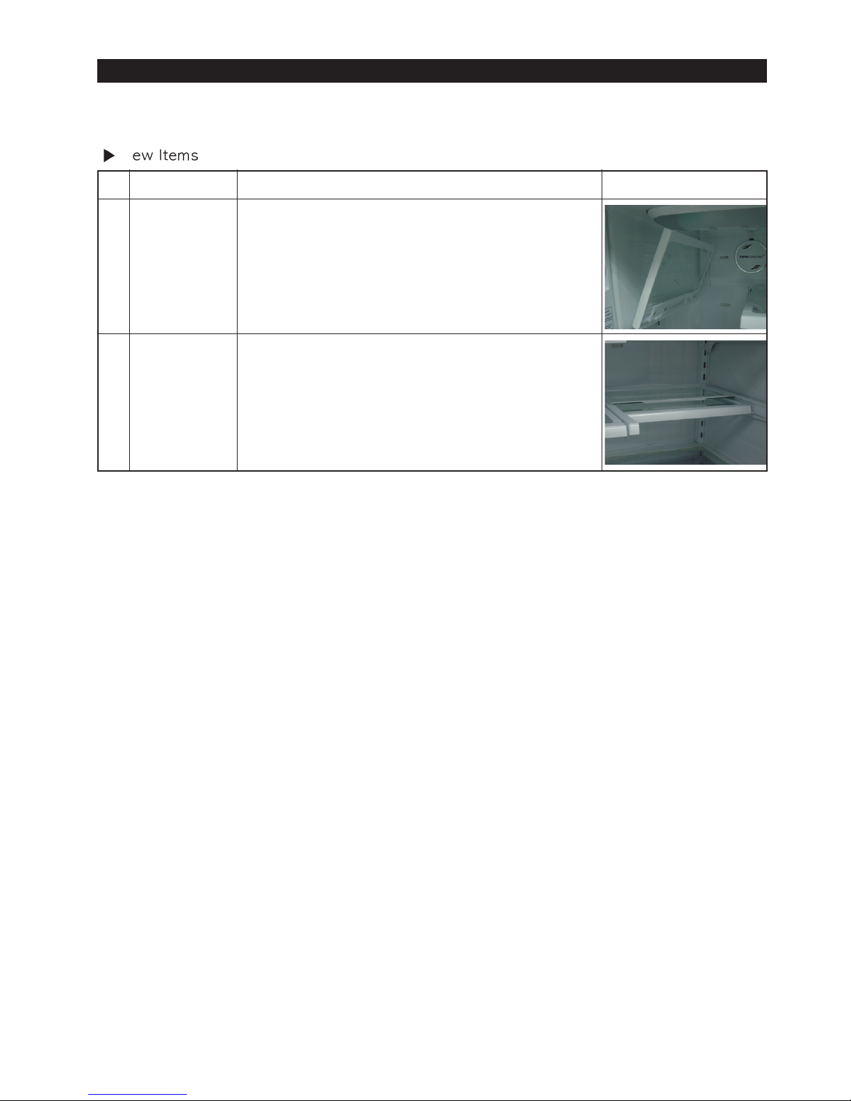
Electronic control from outside of Pantry Cover
●●
Adjustable temperature control ((around 41 (5 ) : Deli /
around 38
(3 ) : Fresh / around 34 (1 ) Chilled )
Temperature control from outside of the Pantry : user
friendly design helps keep foods fresh for longer
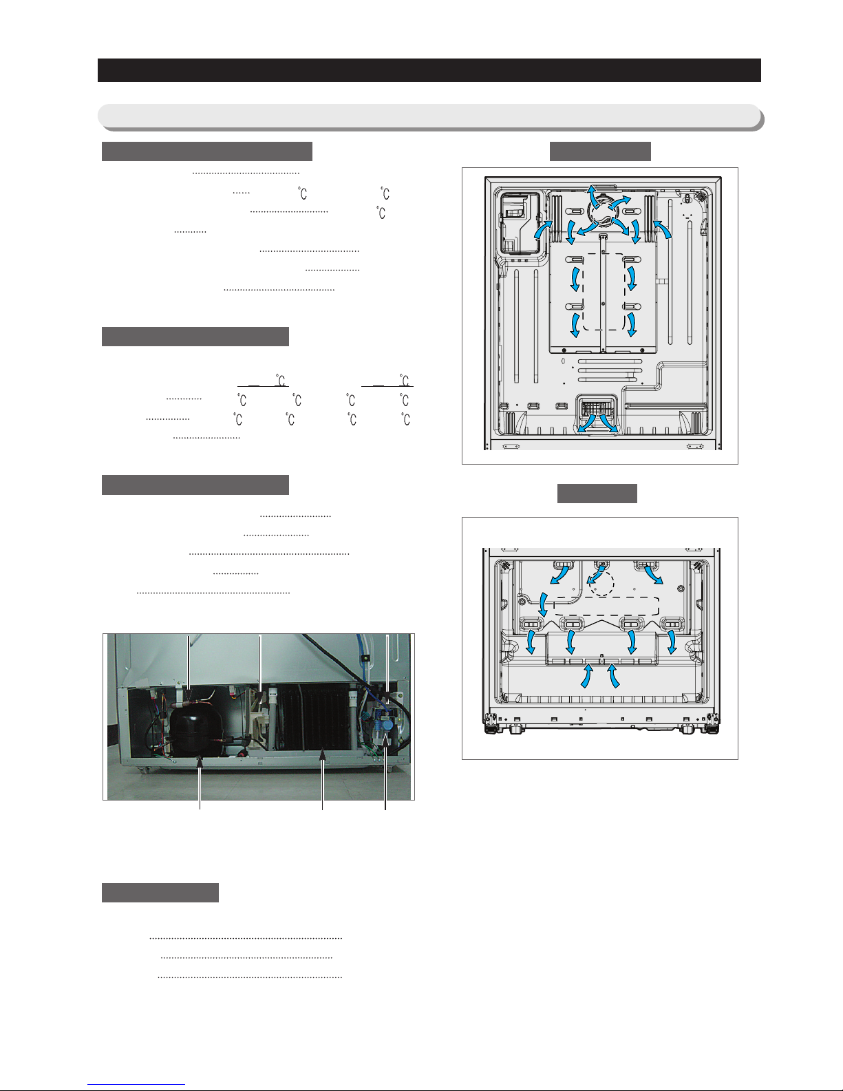
16" Pizza Corner
●●
Can be used for 16" pizza if stand flip tilting pocket.
Ice and Water Dispenser
●●
The ice and water dispenser provides ice and cold water at
any time.
Secure Auto Close Door System
●●
Secure Auto Close Door System
●●
Cool tight doors
●●
Energy saving
●●
Preventing sweat on fridge doors
2-1) Introduction of main function
9
2. PRODUCT SPECIFICATIONS
1
2
3
4
5
6
Display
Pantry
Shelf
Drawer
Ice Maker
Dispenser
Display panel is on the
door to use the Ice &
Water Dispenser more
convenient.
Adding “Deli” mode to
store the foods fresher.
Slide Out Shelf is
adopted to store the
foods more convenient.
The right Vegetable
drawer can be fully taken
out even the left door is
closed.
Compact Ice Maker is
installed for the Ice &
Water Dispenser.
Dispenser provides
water, ice or iced water.
NO Item Details
Display on Top Table Display on Door
Basic Model(RF265AA) New Model(RF26DB**)
Changing Items
10
2. PRODUCT SPECIFICATIONS
1
2
This shelf is attached on the left side of cabinet
and can be folded. This design improves the
space utilization.
Foldable
Shelf
Quick Space
Shelf
The half of this shelf can be slid in.
This design secures enough space to store tall
things.
NO Item Details of New Items
New Model(RF26DB**)
N
11
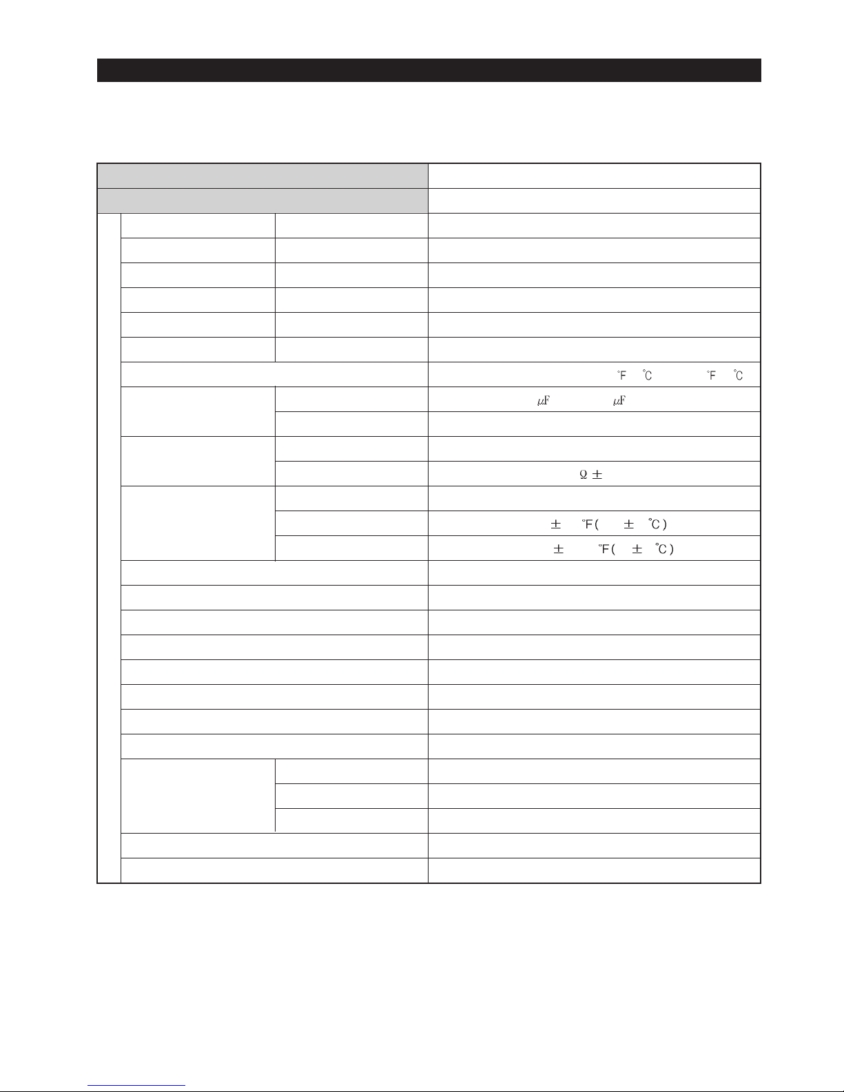
2-2) Specifications
PRODUCT SPECIFICATIONS
Defrost Control From 24 to 32 hrs
Thermo Bimetal Protector 140°F(60
)(off) 104°F(40 )(on)
Defrost Thermistor(502AT) 50°F(10
)(off)
Electrical Rating AC115V 60Hz 11.6 Amps / 220V~240V 50Hz
Maximum Current Leakage 0.25 mA
Maximum Ground Path Resistance 0.1 Ohm
Energy Consumption 570KWh/year
Ambient Temperature 70
℉(21 ) 90℉(32 )
Refrigerator,℉ 34℉(1 )∼46℉(8 ) 34℉(1 )∼46℉(8 )
Freezer,℉ -14℉(-26
)∼8℉(-13 ) -14℉(-26 )∼8℉(-13 )
Run Time,% 40 60
Refrigerant Charge (R134a) 5.64 oz(160g)
Compressor((MK172D-R2U) 897 Btu/hr(0.263kw)
Compressor oil Freol α-10
Capillary tube(Dia, Length) 0.032
""
,118
""((00..8811mmmm,,22999977mmmm))
Dryer Molecular Sieve XH-9
Clearance must be provided for air circulation
AT TOP 1
"" ((2255mmmm))
AT SIDES 0.5
"" ((1155mmmm))
AT REAR 1
"" ((2255mmmm))
Fan
Fan
(Air inlet)(Air inlet)
Heat exchanger
Compressor
C-Fan Noise FilterDryer
Sub-condenser Water Valve
ELECTRICAL SPECIFICATIONS
Freezer
Refrigerator
NO LOAD PERFORMANCE
REFRIGERATION SYSTEM
INSTALLATION
FanFan
(Air inlet)(Air inlet)(Air inlet)(Air inlet)
FanFan
Heat exchangerHeat exchanger
FanFan
Heat exchanger
(Air inlet)(Air inlet)
12
PRODUCT SPECIFICATIONS
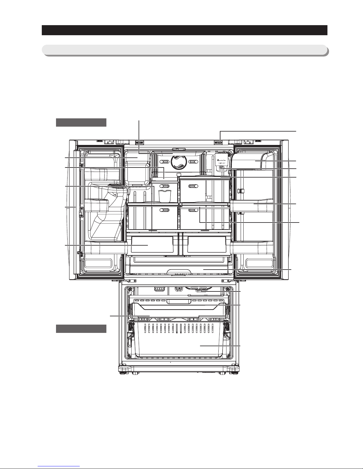
2-3)
Interior Views
Freezer
Refrigerator
Auto Door Closer
Water Filter
Dairy Compartment
Door Bins
Cool Select Pantry
TM
Light
Vertical Hinged
Section
Vegetable & Fruit
Drawers
Tilting Pocket
Light
Pull Out Drawer
Freezer Drawer Bin
Slide-Shelf
Quick-Space
Glass Shelf
Ice-Maker
Foldable-Shelf
Slide-Shelf
13
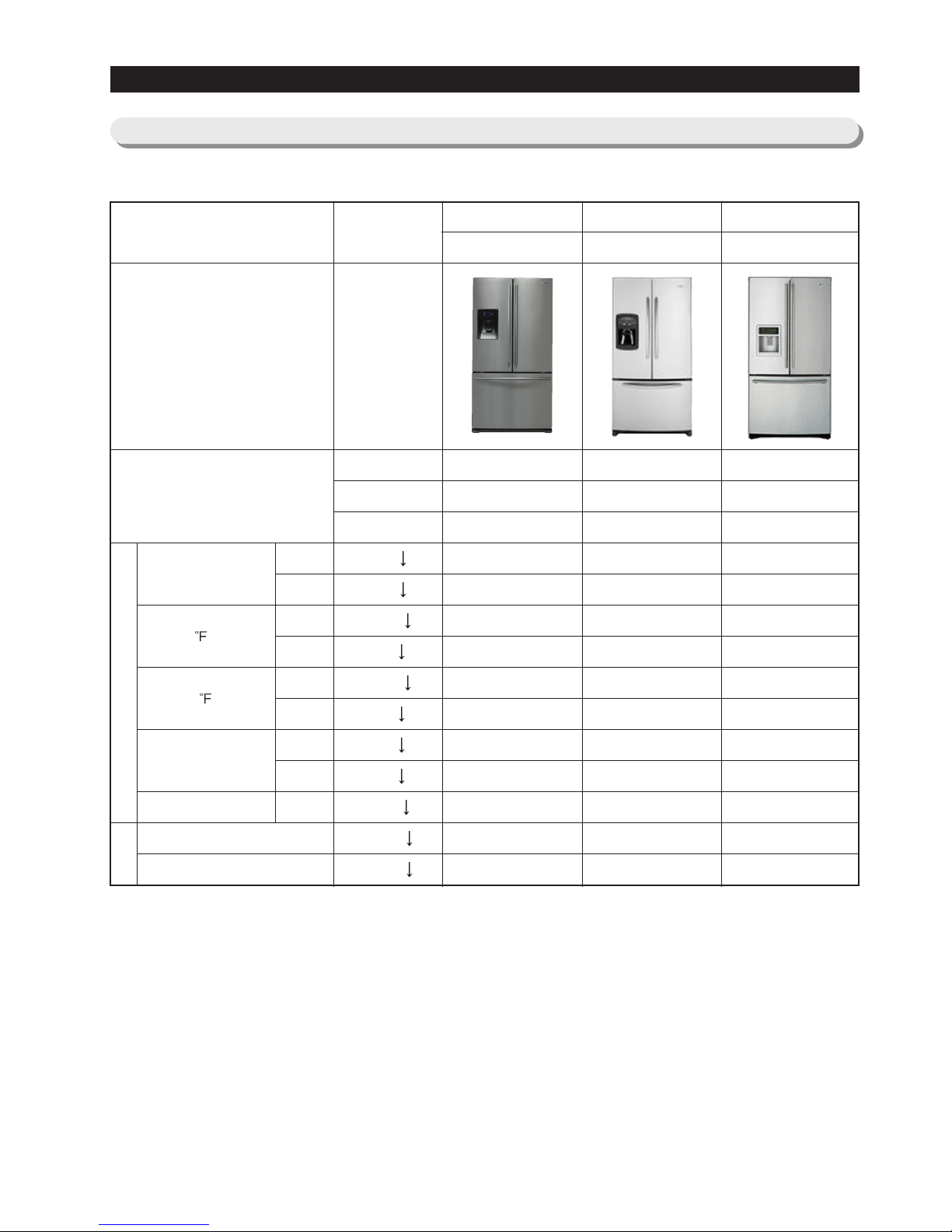
2-4) Model Specification
PRODUCT SPECIFICATIONS
F-Room
R-Room
F-Room
R-Room
F-Room
R-Room
F-Room
R-Room
N-N
Sound power level
Sound Pressure level
Cooling
Speed(Min)
Product Zone
Appearance
ITEM SPEC
89.6 (32°C)
109.4 (43°C)
Temperature
Distribution
(Fridge)
Operation rate
Performance
Noise
Cooling Tech
Door Shape
Special Room
250
250
-26.0
2.0
-18.0
5.0
2.0
2.0
60%
46dB
45dB
SAMSUNG
RF267AA/RF26DB
Twin Cooling
Contour
Cool Select Pantry
209.8
201.8
-28.7
1.0
-21.9
1.1
0.1
0.2
54.0
42.9
41.2
MAYTAG
MFI2568AES
Mono Cooling
Contour
Pantry
246
575
-27.2
1.6
-20.9
5.9
0.6
1.1
60.7
47.0
48.2
LG
LFX25960ST
Mono Cooling
Contour
Pantry
224
232
-28.8
-1.8
-22.5
0.8
1.3
0.5
56.5
41.7
40.1
COLOR
ModelITEM
14
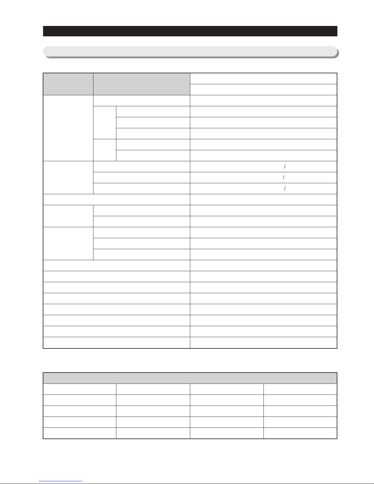
2-5) Model Specification &Specification Chart
PRODUCT SPECIFICATIONS
External size
Net
Capacity
Weight
Packing
D
H
W
Efficiency of volume
On Cabinet
W/O Handle
With Handle
W/O Hinge Cap
With Hinge Cap
Total
Freezer
Refrigerator
Set
Packing
Width
Depth
Height
Black
Real STS
White
Platinum STS
Cabinet (Both sides of Embo)
All Black
Noble STS
Snow White
Noble STS
Door
Empire Black
Versailles Stainless
Snow White
Stainless Platinum
Molding
I Black
Creamy STS
Snow White
Creamy STS
Compressor
Rated Frequency and Frequency
Refrigerant
Foaming agent
Refrigerant Input Amount
Kind of Refrigerator
Motor Rated Consumption Power
Electric Heater Rated Consumption Power
RF267AA / RF26DB
Ice & Water Dispenser with Pantry
35.7 inch (908mm)
29.1 inch (740mm)
32.9 inch (836mm)
35.6 inch (905mm)
68.6 inch (1744mm)
69.8 Inch (1778mm)
25.5Cu.ft (722.1 )
8.2Cu.ft (230.6 )
17.3Cu.ft (491.5 )
50.17%
330 Pounds (150kg)
363 Pounds (165kg)
38.6 Inch (980mm)
39.4 Inch (1001mm)
75.7 Inch (1923mm)
reciprocate
AC 115V/60Hz / AC 230V 50Hz
R 134a
C-Pantane
5.64 oz (160g)
Indirect Cooling Method Refrigerator
140A
380W
Items
Model
15
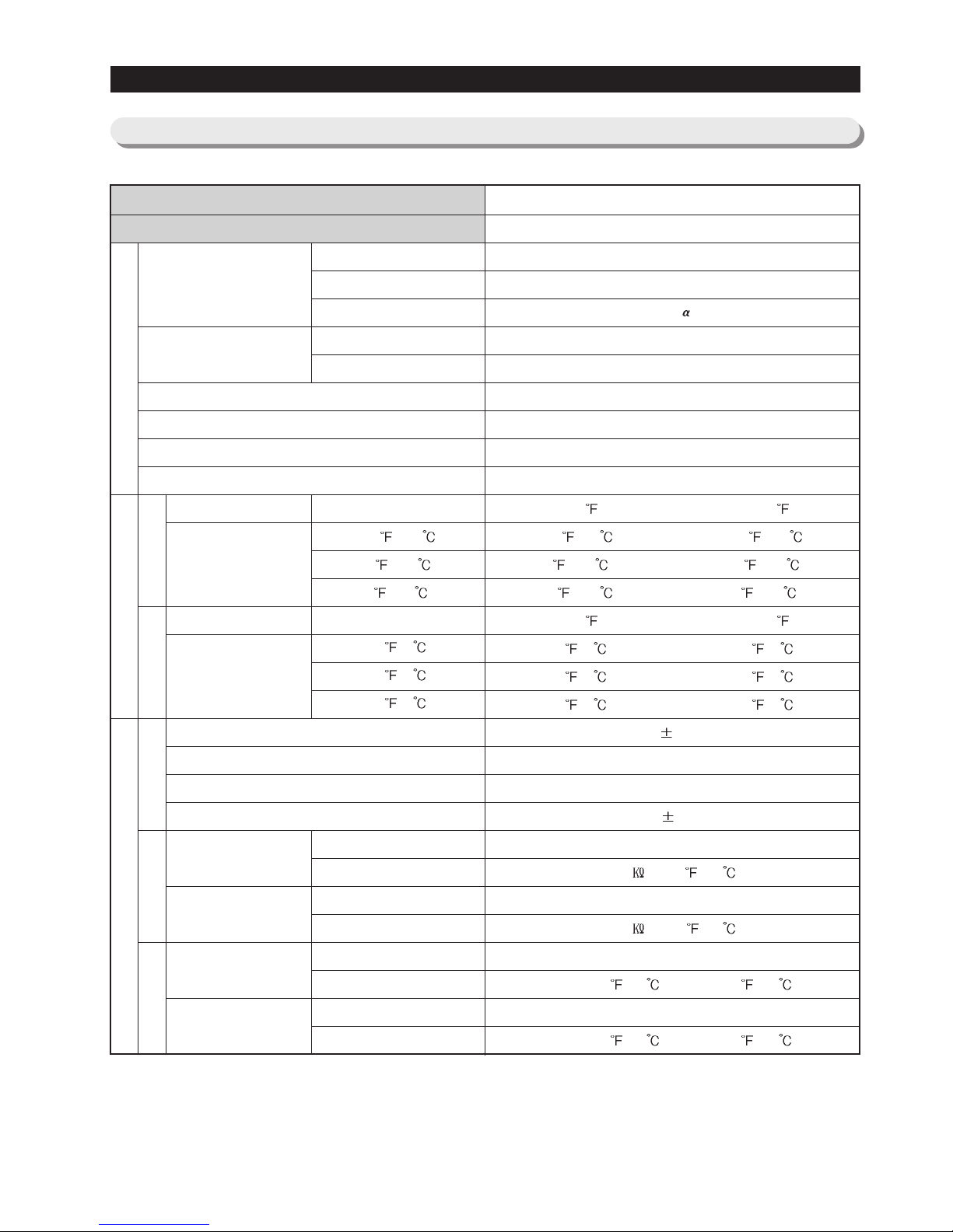
2-5) Model Specification &Specification Chart
PRODUCT SPECIFICATIONS
Compressor
Evaporator
Model
First Defrost Cycle (Concurrent defrost of F and R)
Defrost Cycle(FRE)
Defrost Cycle(REF)
Pause time
THERMISTOR
(F-SENSOR)
502AT
Temperature Selection
-14 (-26 )
-2 (-19 )
8 (-13 )
Model
THERMISTOR
(R-SENSOR)
502AT
F Defrost-Sensor
R Defrost-Sensor
F Bimetal-thermo
Protector
R Bimetal-thermo
Protector
Temperature Selection
34 (1 )
38 (3 )
46 (8 )
Model
SPEC
Model
SPEC
Rated
Operating temperature
Rated
Operating temperature
Condenser
Dryer
Capillary tube(Dia x Length)
Refrigerant
Model
Starting type
Oil Charge
Freezer
Refrigerator
MK172D-R2U / MK190QL2U
R.S.C.R
FREOL - 10
SPLIT FIN TYPE
SPLIT FIN TYPE
Forced and natural convection type
Molecular sieve XH-9
0.032” x 118” (0.81mm x 2997mm)
R134a
6hr 10min
12~23hr(vary according to the conditions used)
6~11hr(vary according to the conditions used)
12 1min
THERMISTOR (502AT)
5.0 at 77 (25 )
THERMISTOR (502AT)
5.0 at 77 (25 )
AC 125V 10A / AC 250V 3A
Off : 140 (60 ) / On : 104 (40 )
AC 125V 10A / AC 250V 3A
Off : 140 (60 ) / On : 104 (40 )
ON( )
-11 (24 )
1 (-17 )
11 (-12 )
ON( )
36 (2 )
40 (4 )
48 (9 )
OFF( )
-17 (-27 )
-5 (-21 )
5 (-15 )
OFF( )
32 (0 )
36 (2 )
44 (7 )
Specification
RF267AA / RF26DB
Components for FreezerDefrost Related Components
FreezerRefrigeratorDefrost Cycle
Defrost SensorBimetal
Room Temperature Sensor Components
16
PRODUCT SPECIFICATIONS
Items
Model
Defrost Heater(FRE)
Defrost Heater(REF)
DISPENSER Heater
FRENCH Heater
ICE Duct Heater
Water Tank Heater
Interlock with French Heater
-
Interlock with Defrost Heater (FRE)
-
Running
Starting
Model
Operation
Model
Temp.ON
Temp.OFF
Condenser for COMP
(Package type)
Starting-Relay
Over load Relay
Rated Voltage
MOTOR-BLDC(FRE)
MOTOR BLDC(ICE ROOM)
MOTOR-BLDC(REF)
MOTOR-BLDC(CIRCUIT)
MOTOR-DAMPER(PANTRY)
Lamp(FRE)
Lamp(REF)
Conducting af F Defrost
Conducting at R Defrost
Door Switch
FRE
REF
REF(ICE ROOM)
Power cord
Earth Screw
Bimetal thermo For Preventing Overheating of Refrigerator Lamp
AC 115V, 240W / AC 230V, 240W
AC115V, 120W / AC 230V, 120W
AC115V, 3W / AC 230V, 3W
AC115V, 10W / AC 230V, 10W
AC115V, 4W / AC 230V, 4W
DC 12V, 2W
AC125V 10A / AC250V 3A Off: 140 (60 )/ On : 104 (40 )
12 ,250V / 5 ,450V
-
J531Q33E100M200-2
10 20%
4TM435RFBYY-53
266 41 130 5
141.8 48.2 61 9
AC 115V/60Hz / 220~240V/50Hz
DC12V / FDQT06SS3
DC12V / DREP5020LB
DC12V / FDQT06SS3
DC12V / FDQT04SS2
DC12V / NSBY001TA1
AC 120V / 60W(1EA) / AC 230V 40W(1EA)
AC 120V / 60W(2EA) / AC 230V 60W(2EA)
AC 125V 1.5A (1EA) / AC 250V 0.5A
DC200V 1.5A / MS-406-SS-01(2EA)
125~250V /11A, EMB606
AC125V 15A / AC 250V 10A
BSBN (BRASS SCREW)
Specification
RF267AA / RF26DB
Electric Components
17
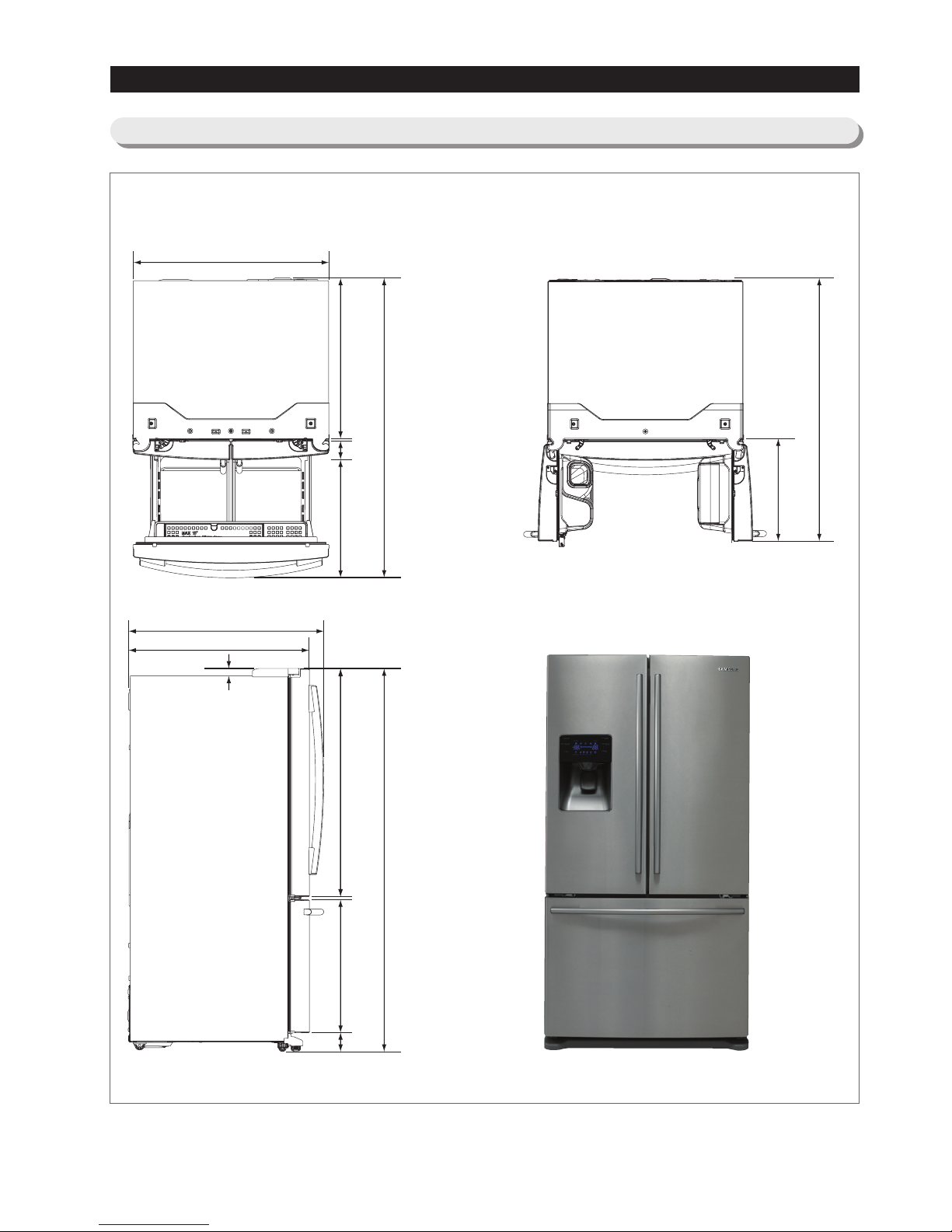
PRODUCT SPECIFICATIONS
29.1"(739mm)
3.4"(86mm)
21.6"(549mm)41.7"(1059mm)
0.6"(15mm)
69.8"(1778mm)
1.3"(34mm)
32.9"(836mm)
35.6"(905mm)
35.7"(908mm)
24.3"(617mm)
3.4"(86mm)
54.5"(1384mm)
18.7"(475mm)
47.8"(1214mm)
2-6)Dimensions of Refrigerator (Inches)
18
PRODUCT SPECIFICATIONS
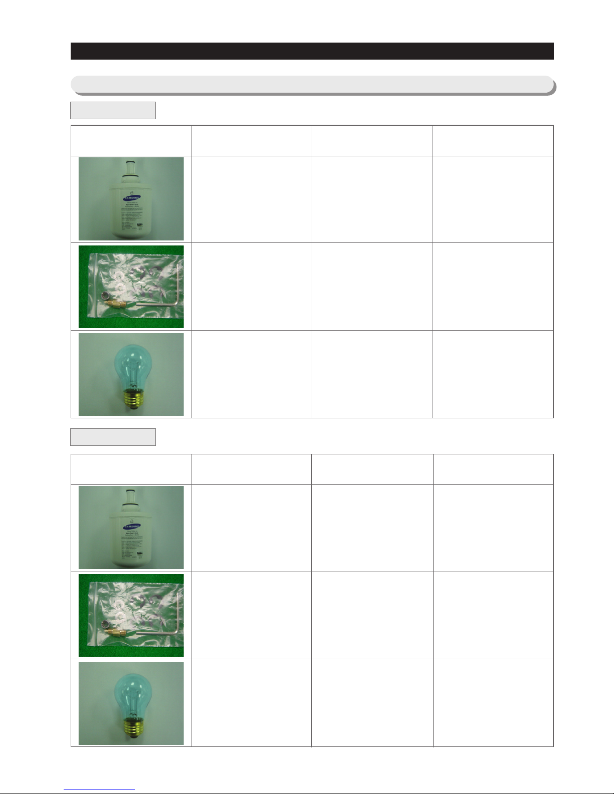
2-7) Optional Material Specification
Part Name
FILTER
WATER-ASSY
DA29-00003B
ASSY-PACKING
SUB
DA99-00240G
LAMP INCANDENT
4713-001223
Part Code AMOUNT
1
1
3
AMOUNT
1
1
3
Part Name
ASSY-INSTALL FILTER
DA97-01469W
PIPE-CONNECT
WATER PACKING
DA62-01329A
LAMP INCANDENT
4713-001232(REF) : 60W
4713-001201(FRE) : 40W
Part Code
RF267AA
RF26DB
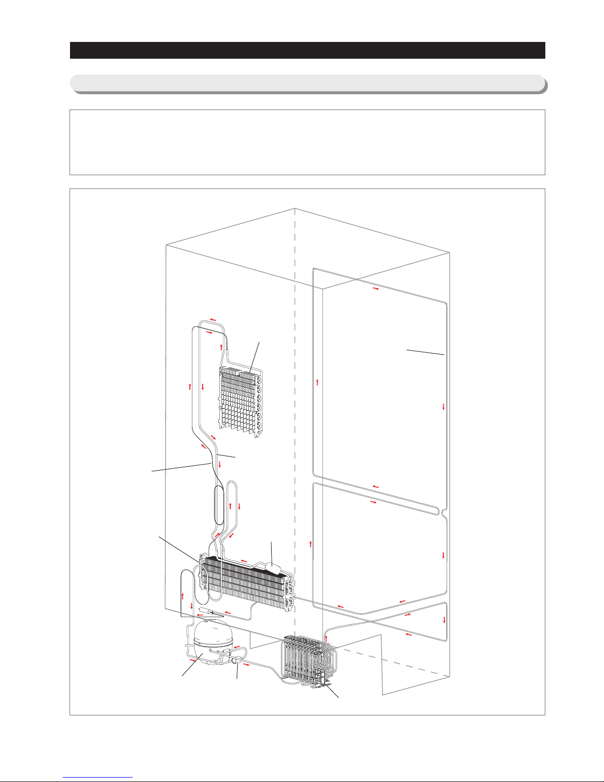
19
Compressor → Sub-condenser → Hot Pipe → Dryer → Capillary Tube → Refrigerator Evaporator → Freezer
Evaporator→ Suction Pipe → Compressor
Refrigerator
Evaporator
Freezer
Evaporator
Suction Pipe
Capillary Tube
Accumulator
Compressor
Sub Condenser
Hot Pipe
Muffler
PRODUCT SPECIFICATIONS
2-8) Refrigerant Route in Refrigeration cycle
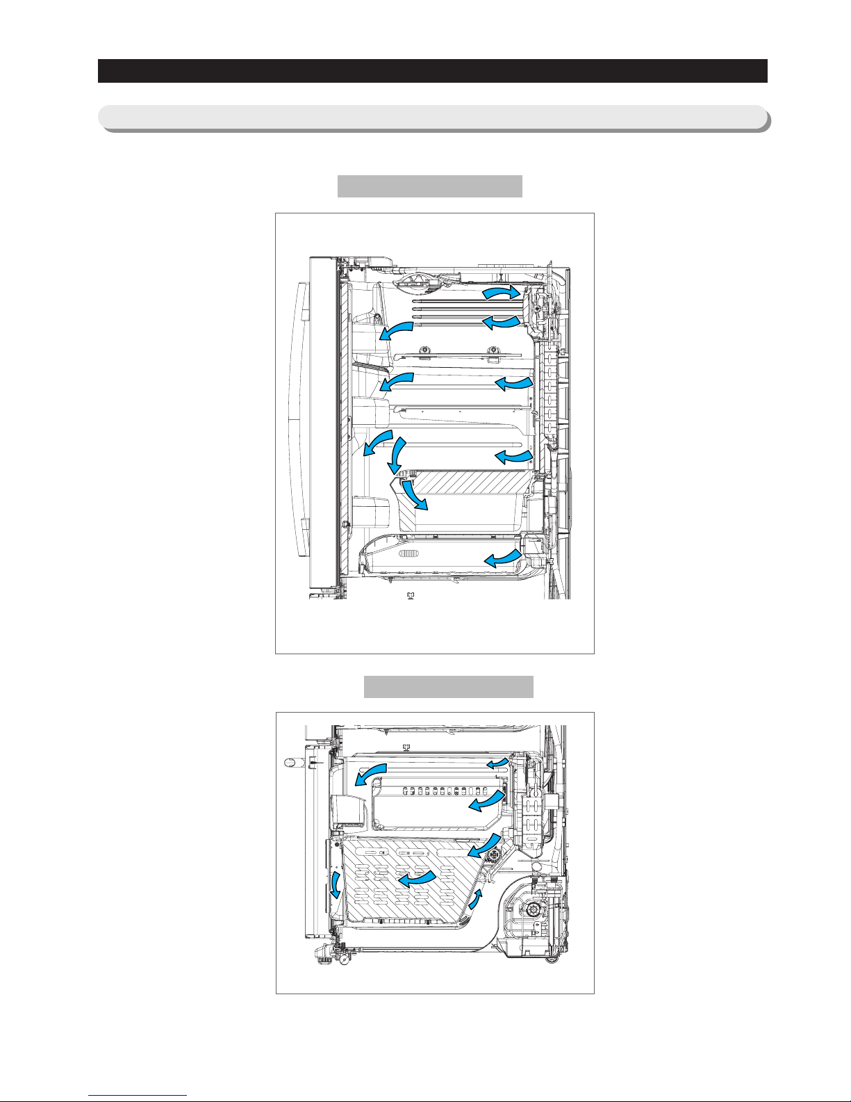
20
Refrigerator
PRODUCT SPECIFICATIONS
2-9) Cooling Air Circulation
Freezer

21
3. DISASSEMBLY AND REASSEMBLY
3-1) PRECAUTION 22
3-2) REFRIGERATOR DOOR 23
3-3) DOOR SWITCH IN REFRIGERATOR 25
3-4) DOOR GASKET 25
3-5) DOOR HANDLE 25
3-6) REFRIGERATOR LIGHT 26
3-7) COVER-DISPLAY & WATER-DISPENSER 26
3-8) WATER-DISPENSER 27
3-9) GLASS SHELF 28
3-10) FOLDABLE GLASS SHELF 29
3-11) VEGETABLE & FRUIT DRAWERS SHELF 29
3-12) COOL SELECT PANTRY 30
3-13) WATER TANK 31
3-14) MOTOR DAMPER 33
3-15) WATER FILTER (DISASSEMBLY) 33
3-16) WATER FILTER (REASSEMBLY) 34
3-17) GALLON DOOR BIN 34
3-18) VERTICAL HINGED SECTION 35
3-19) EVAPORATOR COVER IN REFRIGERATOR 36
3-20) EVAPORATOR IN REFRIGERATOR 37
3-21) FREEZER DOOR 38
3-22) PULL OUT DRAWER 39
3-23) ICE-MAKER 40
3-24) FREEZER LIGHT 41
3-25) DOOR SWITCH IN FREEZER 41
3-26) EVAPORATOR COVER IN FREEZER 42
3-27) EVAPORATOR IN FREEZER 42
3-28) MACHINE COMPARTMENT 43
3-29) ELECTRIC BOX 46
22
ASSEMBLY & DISASSEMBLY
• Unplug the refrigerator before cleaning and making repairs.
• Do not dissemble or repair the refrigerator by yourself.
- You run risk of causing a fire, malfunction and/or personal injury.
• Remove any foreign matter or dust from the power plug pins.
- Otherwise there is a risk of fire.
• Do not use a cord that shows cracks or abrasion damage along its length or at either end.
• Do not plug several appliances into the same multiple power board. The refrigerator should always be
plugged into its own individual electrical which has a voltage rating that matched the rating plate.
- This provides the best performance and also prevents overloading house wiring circuits, which could
cause a fire hazard from overheated wires.
• Do not install the refrigerator in a damp place or place where it may come in contact with water.
- Deteriorated insulation of electrical parts may cause an electric shock or fire.
• The refrigerator must be grounded.
- You must ground the refrigerator to prevent any power leakages or electric shocks caused by current
leakage from the refrigerator.
• Do not put bottles or glass containers in the freezer.
- When the contents freeze, the glass may break and cause personal injury.
• Do not store volatile or flammable substances in the refrigerator.
- The storage of benzene, thinner, alcohol, ether, LP gas and other such products may cause
explosions.
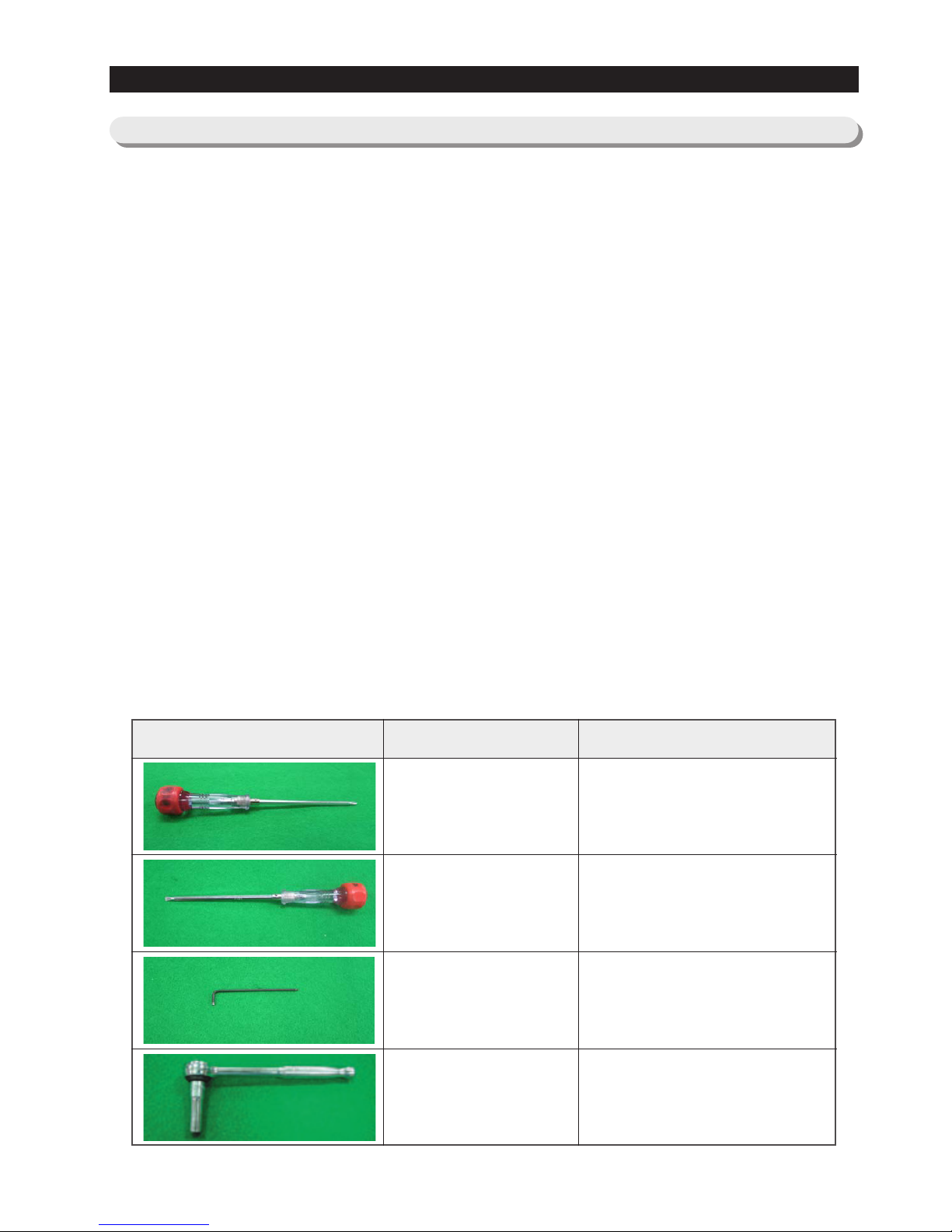
- NEED TOOL
3-1) PRECAUTION
IMAGE ITEM USE
Phillips Head Driver
Use for assembling and
disassembling of screw
Flat Head Driver
Use for assembling and disassembling
of HomeBar, Dispenser, Deli
Cartessen Box, Main PBA etc...
Hex Wrench Ø2mm
Use for assembling and
disassembling of Handle
Socket Wrench Ø10mm
Use for assembling and
disassembling of Door Hinge
23
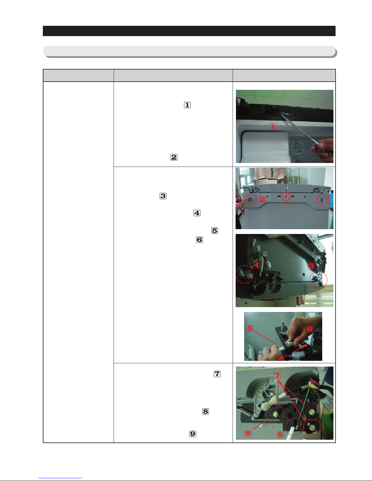
3-2) Refrigerator Door
DISASSEMBLY AND REASSEMBLY
Refrigerator
Door
Part Name How To Do Descriptive Picture
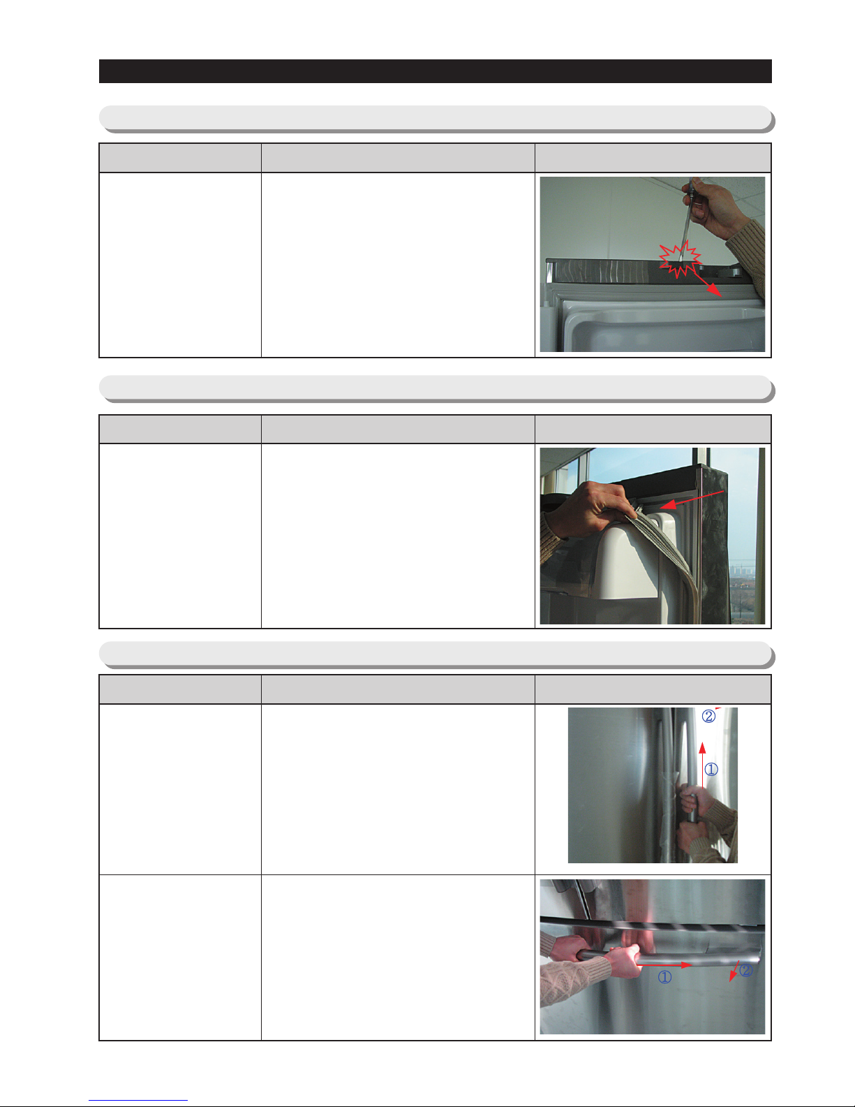
1. With the door opened, remove
the Top Table cap(
) with a Flat
head screwdriver, and close the
door.
2. Remove the 3 screw holding
down the Top Table and remove
the Top Table(
).
3. Disconnect the electrical
connector(
) above the upper
right door hinge and the 3
electrical connectors( ) above
the upper left door hinge.
Disconnect the water tube( ) by
pulling the tube fitting( ) apart
as shown in the picture.
4. Remove the 3 hex head bolts(
)
found attatched to the upper left
and right door hinges with a
Wrench(10mm).
With a Philips head screwdriver,
remove the ground screw( ) found
attatched to the upper left and right
door hinges. Remove the upper left
and right door hinges( ).
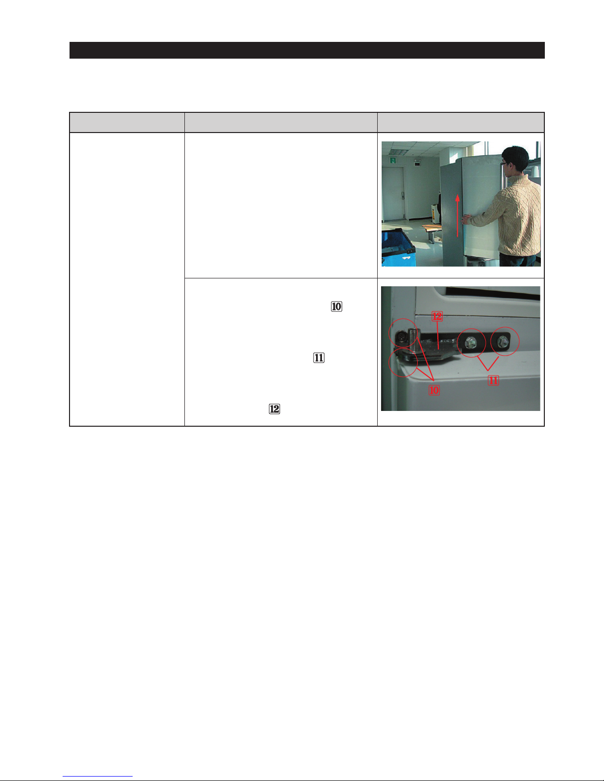
24
DISASSEMBLY AND REASSEMBLY
Refrigerator
Door
Part Name How To Do Descriptive Picture
5. Lift the door straight up to
remove.
6. With a Philips head screwdriver,
remove the two screws (
)
attatched to the lower left and
right door hinges.
With a Wrench(10mm), remove
the 2 hex head bolts(
)
attatched to the lower left and
right door hinges.
Remove the lower left and right
door hinges(
).
25
3-3) Door Switch In Refrigerator
DISASSEMBLY AND REASSEMBLY
3-4) Door Gasket
3-5) Door Handle
Door Switch
In Refrigerator
Part Name How To Do Descriptive Picture
1. Remove the magnet switch with
using a flat-blade(-) screwdriver.
(Refer to the picture)
Door Gasket
In Refrigerator
Part Name How To Do Descriptive Picture
1. Remove the door-gasket by
pulling it out of the retaining
channel.
Door Handle
Refrigerator
Door Handle
Freezer
Part Name How To Do Descriptive Picture
1. Remove the door handle of
refrigerator by lifting it up and
pulling it out.
(Refer to the picture)
1. Remove the door handle of
freezer by pushing it to the right
and pulling it out.
(Refer to the picture)
26
DISASSEMBLY AND REASSEMBLY
3-6) Refrigerator Light
3-7) Cover-display & water-dispenser
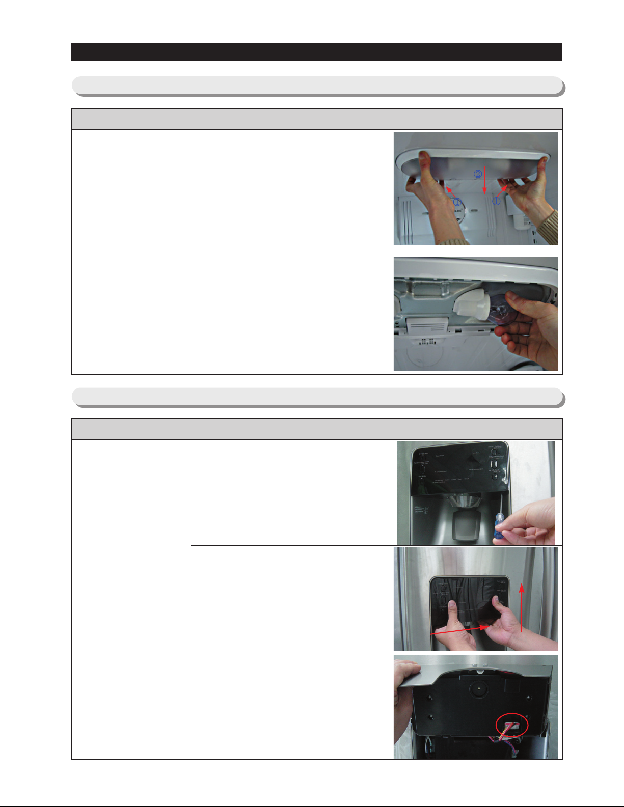
Cover-display
Part Name How To Do Descriptive Picture
1. Insert a flat-blade screwdriver
on the slot as shown in the
picture, and unlock the tabs.
2. Remove the display cover by
pushing it to the right side and
pulling it up.
3. Disengage the housing connect
of display cover
Refrigerator
Light
Part Name How To Do Descriptive Picture
1. Remove the light cover by
pulling it down with pushing the
rear of light cover.
2. Remove the lamp by turning it
counterclockwise.
①
②
27
DISASSEMBLY AND REASSEMBLY
Cover-display
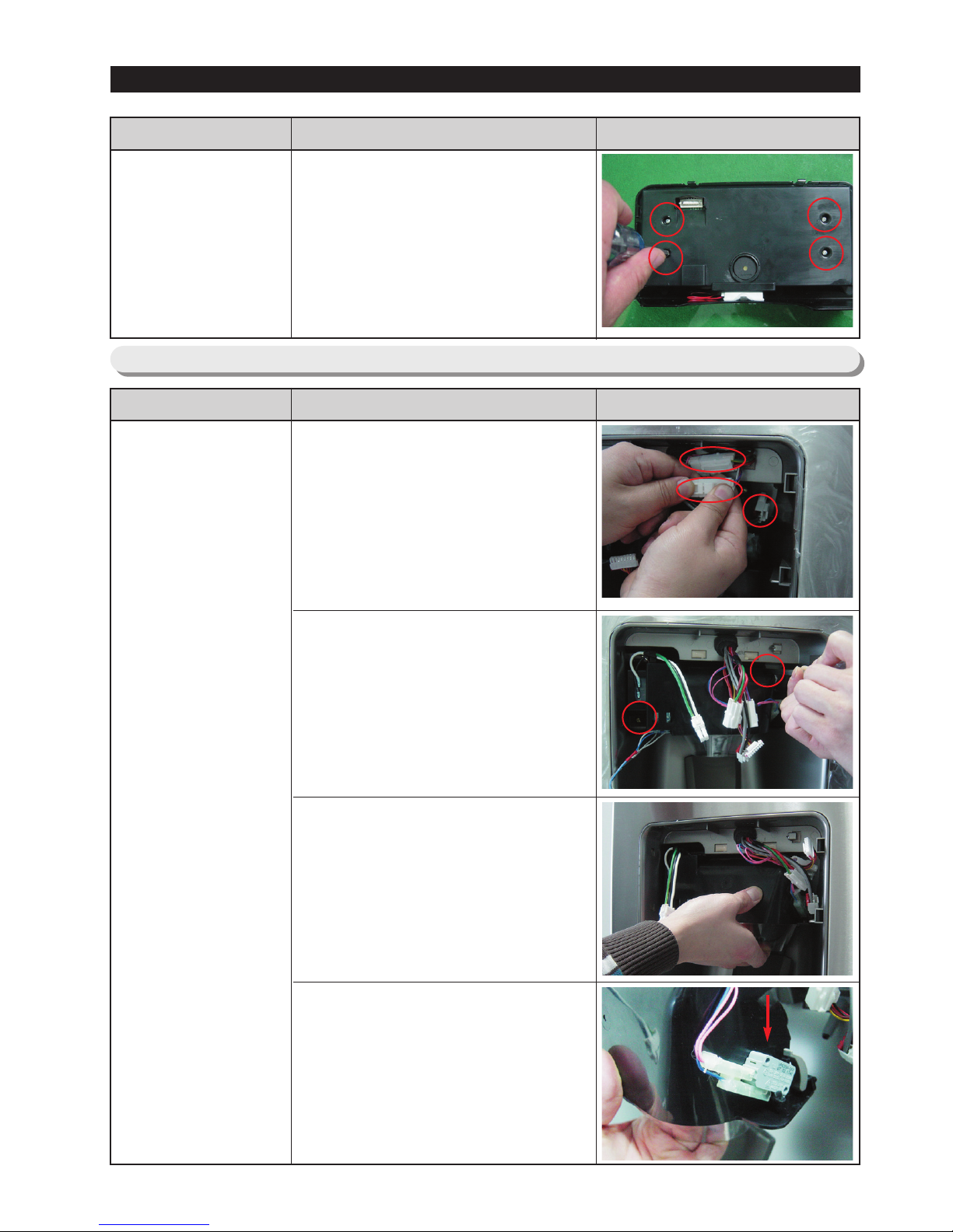
Part Name How To Do Descriptive Picture
4. Remove 4 screws of coverdisplay
3-8) Water-dispenser
Water-dispenser
Part Name How To Do Descriptive Picture
1. Disengage the 3 Housing
Connect.
2. Remove 2 screws of the
CaseIce,Route Assy.
3. Pull the Case-Ice,Route Assy.
4. Push the hook and remove the
Micro Switch.
28
DISASSEMBLY AND REASSEMBLY
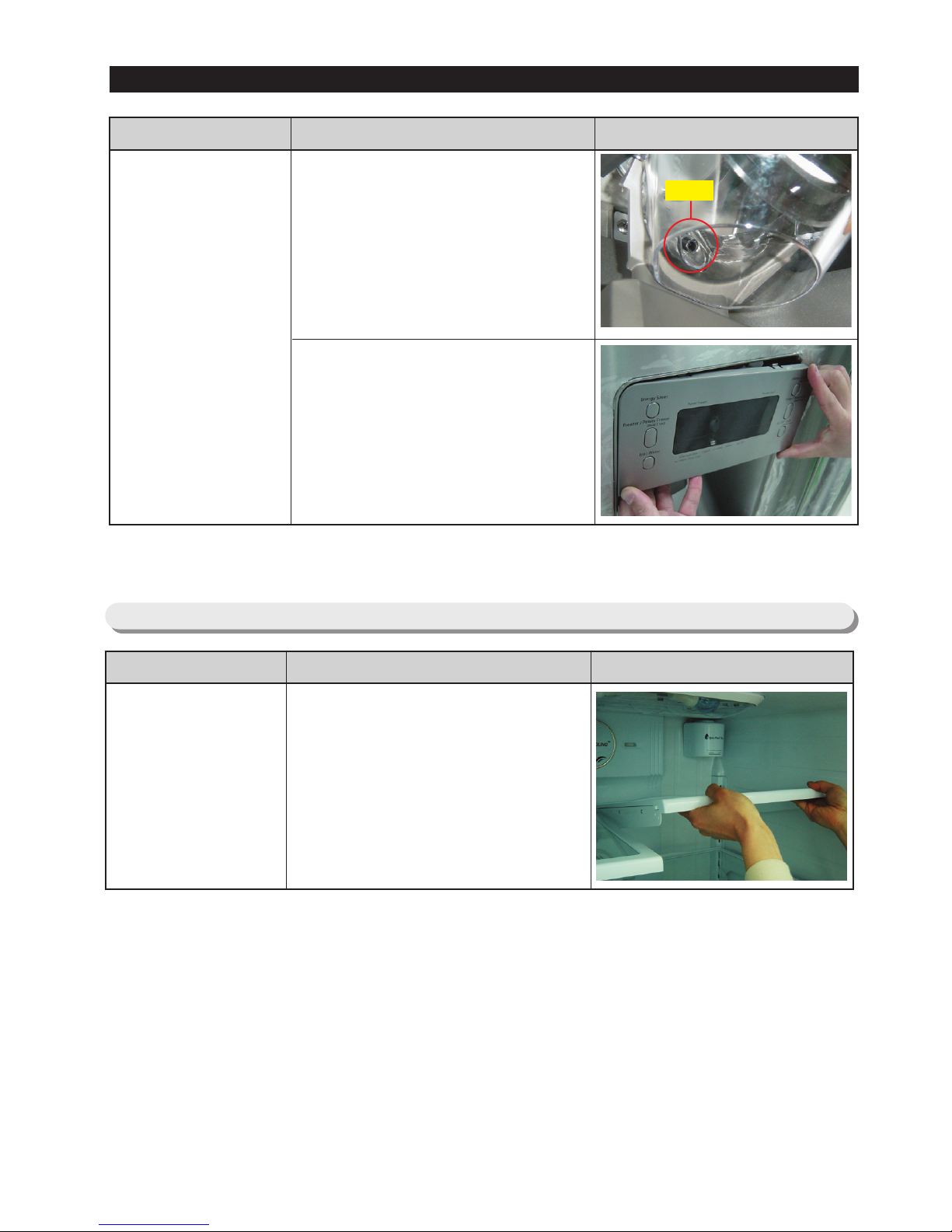
Water-dispenser
Part Name How To Do Descriptive Picture
1. Assembly shall be the contrary
order from the disassemble.
Case-Rce and Route shall be
assembled inside of hose.
Otherwise, assemble cannot be
accomplished.
2. When assembling Cover-
Display, first insert it from
leftside and then assemble to
rightside.
Otherwise, the tab can be
broken.
3-9) Glass Shelf
Glass Shelf
Part Name How To Do Descriptive Picture
Remove the shelf by lifting the
front plane of the shelf up and
pulling it out.
hose
 Loading...