

Samsung RF263 Series Repair Manual

- 1/65 -
HA Repair Guide
Refrigerator
AW1(12)-RF263*
- 2/65 -
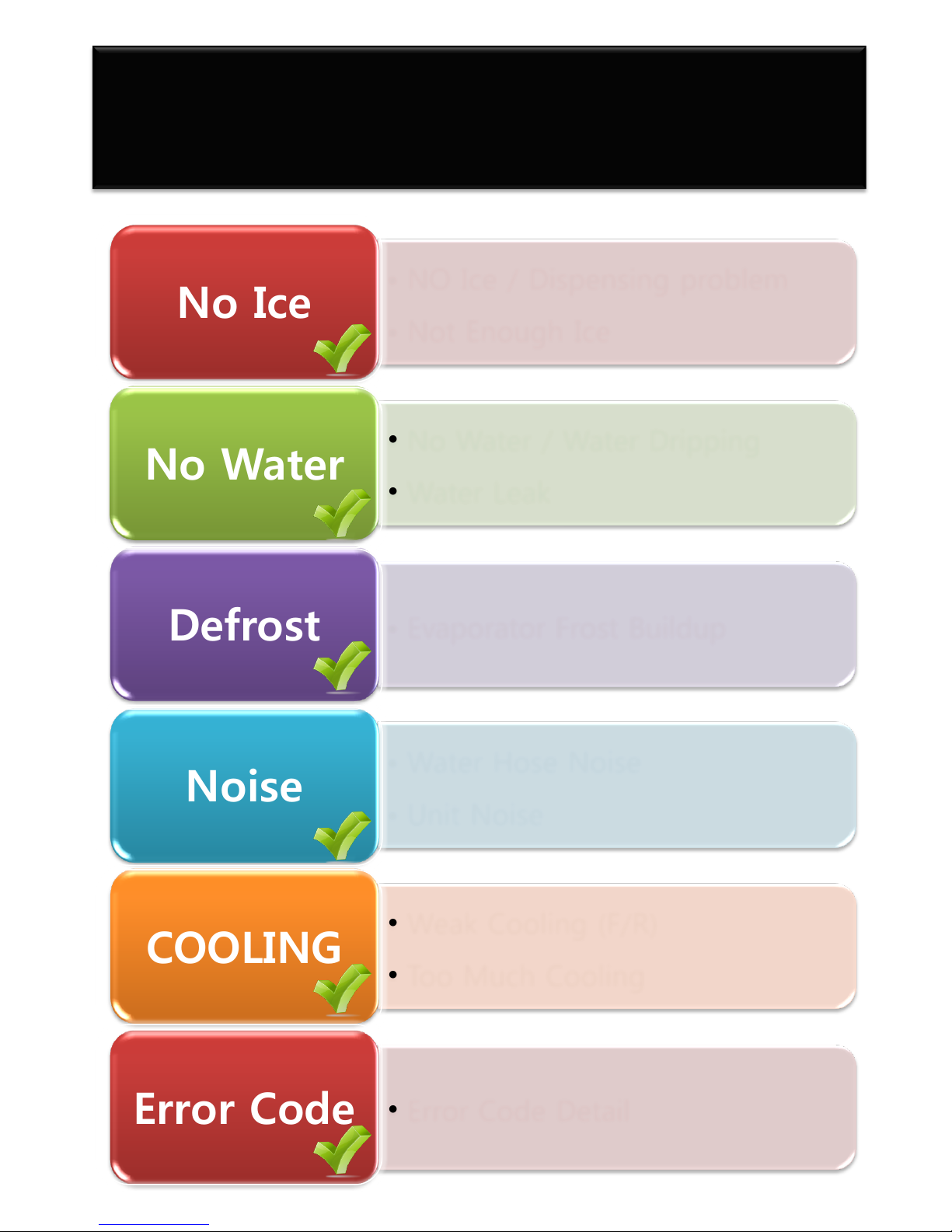
• NO Ice / Dispensing problem
• Not Enough Ice
No Ice
• No Water / Water Dripping
• Water Leak
No Water
• Evaporator Frost Buildup
Defrost
• Water Hose Noise
• Unit Noise
Noise
• Weak Cooling (F/R)
• Too Much Cooling
COOLING
• Error Code Detail
Error Code
AW1(12)PJT Repair Guide
[ RF263* ]
- 3/65 -
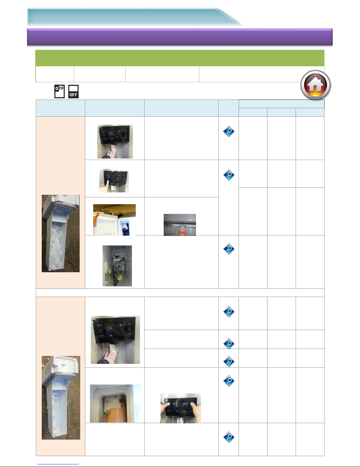
● Ice
#1. Symptom : No Ice Repair distribution diagram
Check-1
Reason Step
Check-2
Tip
Code
Block
# 1
# 2
# 3
Ice Bucket
Full
(Dispensing
problem)
Display Issue
Inspect Display Water
& Ice selecting
1-1
Panel-
PBA
Wire
Harness
Main
PBA
Lever S/W problem
Inspect Lever S/W
operation
1-2
Panel-
PBA
Wire
Harness
Ice
Bucket
Auger
Motor
S/W
Wire
Harness
Auger S/W failure
Inspect Auger Motor
S/W operation
Auger Motor Prob
Inspect ASSY
Auger Motor
operation
1-3
ASSY
Auger
Motor
Wire
Harness
Main
PBA
Ice Bucket
Empty
(Ice making
problem)
Ice maker water
supply issue
Inspect Water
connection / supply
2-1
External
Conn.
(water
supply)
Water
Hose
Filter
Ice Full sensing
failure
2-2
IR
Sensor
Wire
Inspect Ice Valve
operation
2-3
Wire
Harness
Ice Valve
Ice maker/ Sensor
/ Fan Motor issue
Self-diagnosis
Display “Energy
Saver” +”Alarm”
2-4
Ice
Maker,
Sensor,
Fan
Damper
Wire
Harness
Main
PBA
Cooling power
failure
(Ice melting
in Tray)
Measure cooling
power inspection
Comp / Fan motor
inspection
2-5
Comp
Relay
Cycle
Shield
System
C-fan
Chassis
Project
Basic Model
Type
FDR
AW1-12
RF263*
Direct Ice Maker
※ Check the Display as “ICE off”

- 4/65 -
Step 1
① Check for “Child Lock” icon
② Check “Ice Type/Water” Key.
- If it is normal Inspect “Tip 1-2”
- If it is abnormal Inspect Step 2
Step 2
① Check PANEL PBA WIRE HARNESS
Pin connection / switching
- Inspection of 1~5Wire
Verify that the wires are in
the correct order in the connector
① Disassemble the HINGE-UPP COVER, check
the WIRE HARNESS Pin connection/switching
connection and verify the correct sequence
- Inspect BLK / BRN / RED / ORG / YEL
Wire
Step 3
① Disassemble Main PBA Cover in the back
Inspect CN50 ①~⑤Wire Pin contacting and
switching
- BLK / BRN / RED / ORG / YEL Verify that
the wires are in
the correct order in the connector
① If there is no problem on all,
- Replace the PANEL PBA
Check Point
Check the “Ice Type/Water” Key selecting operation.
Tip 1-1. Inspect Display “Ice Type / Water” selecting
CN 50
- 5/65 -
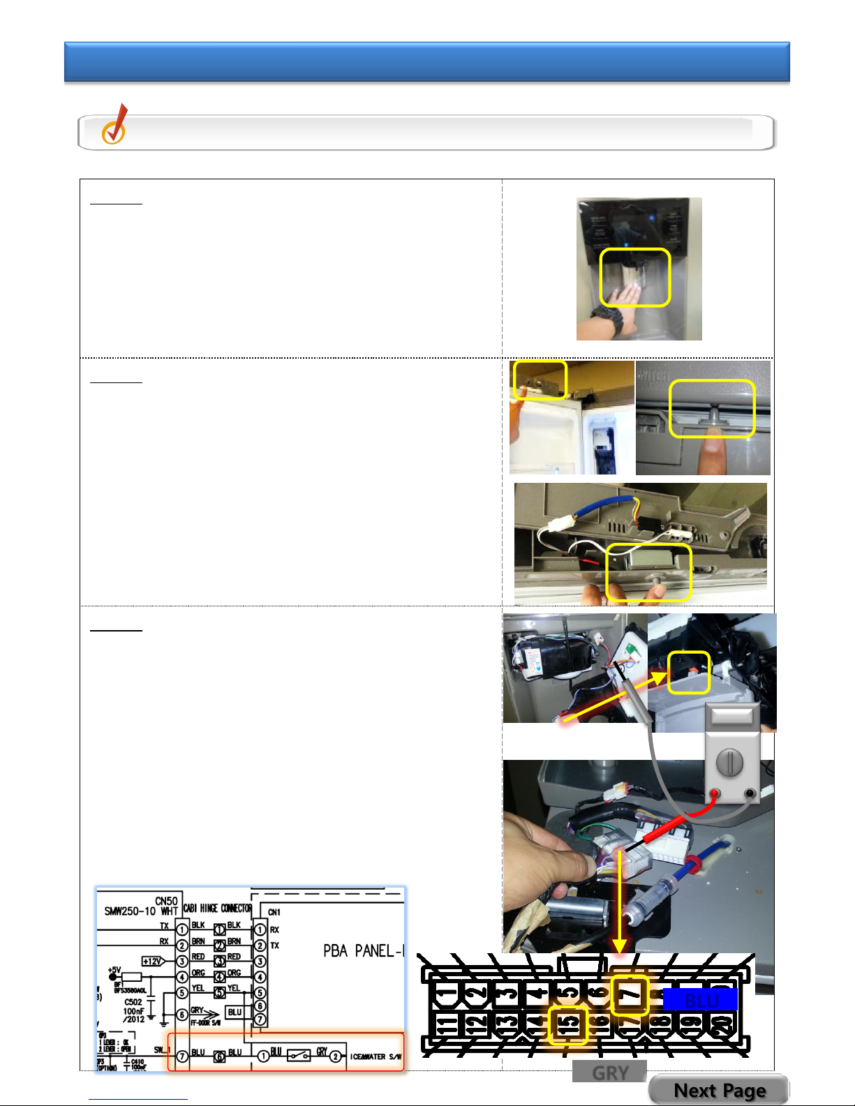
Step 1
① Push the DISPENSER LEVER to check Auger
Motor rotating sound. Auger motor is in
the Ice Room.
- If No operation sound, go to Step 2
inspection
- If operation sound, go to Step 4
inspection
Step 2
① Check Auger Motor S/W that is on the top
of Left FF Section Door.
- Inspect S/W with F room door closed
② Using an Ohmmeter, check for“0Ω” with the
S/W plunger pushed in by hand.
※ If the door S/W has failed, the auger
motor cannot work.
Step 3
① Disassemble the Display and check the Micro
LED S/W, located at the back of the Lever.
※ (Check for broken or stuck switches)
When there is no problem found,
① Disassemble HINGE-UPP COVER, and check
the WIRE HARNESS connection
- Inspect CONNECTOR
No.7(BLU)+No.15(GRY)
② Inspect Main PBA Connector
- Inspect CN50 No.5(YEL) and No.7(BLU)
Wire
Check Point
Inspect the Dispenser Lever S/W operation.
Tip 1-2. Inspect Lever S/W & Auger Motor S/W operation
BLU
GRY
Next Page
- 6/65 -
Step 3 (COVER ICE ROUTE S/W failure)
① When COVER open as failure of operation
② Inspect the CONNECTOR OPEN
③ Inspect the MOTOR S/W TOUCH failure
- Rotate continuously when both 2 S/W are
not pushed
④ Inspect BLUE / WHITE S/W exchanging
⑤ Replace ASSY CASE-LEVER DISP .
COLOR CHK
- 7/65 -
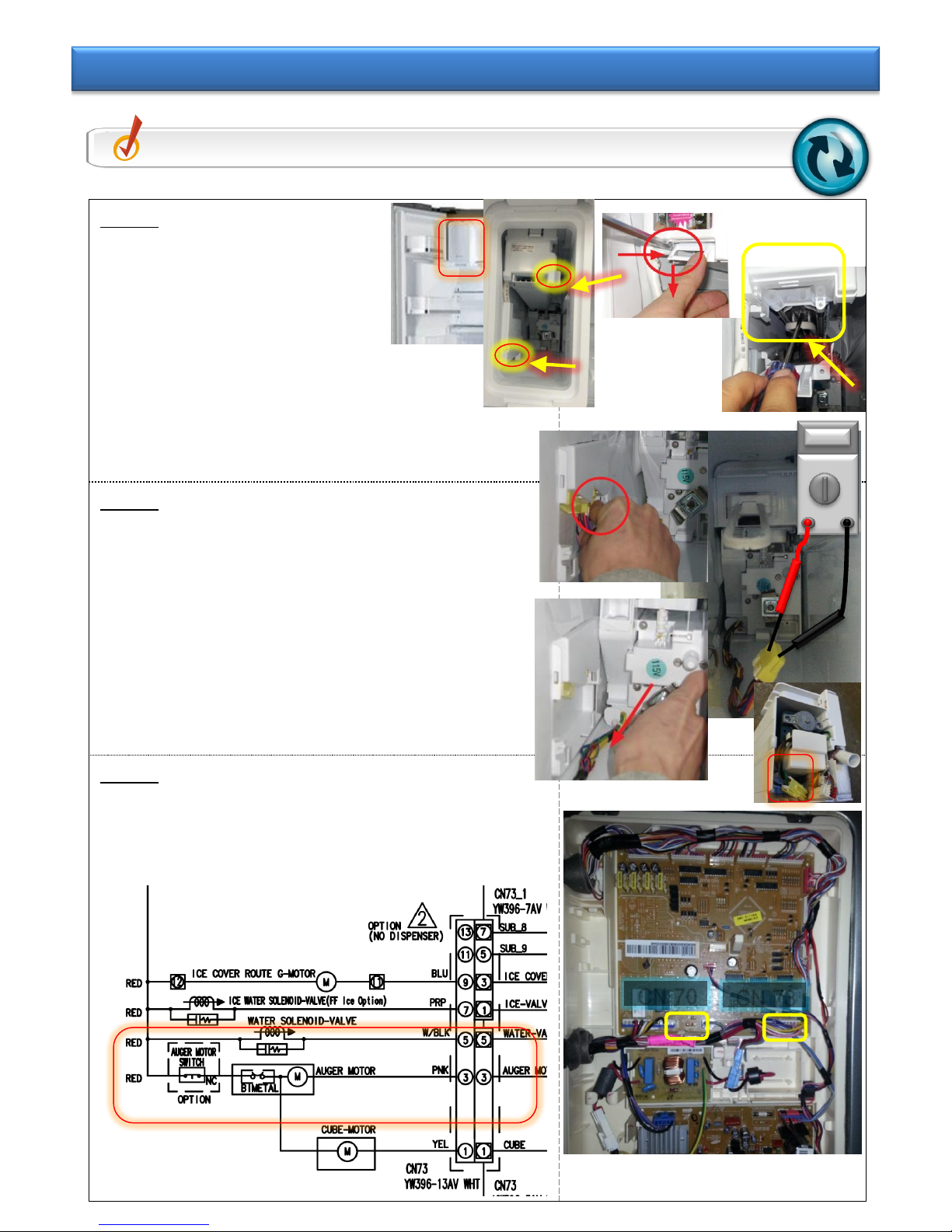
Step 1
① Remove the Ice bucket
in ice room
① Remove 2 screws as shown
② Remove the ice maker after pulling the
cooling pipe which is in the bottom of ice
maker.
Step 2
① Remove the Auger Motor and inspect the
Motor
- Normal = GRY+BLK 3~5 Ω
- Defective = Open or 0 Ω
Step 3
① Inspect the Main PBA + CONNECTOR Wire
- CN73 No.3(PNK) + CN70 No.5(RED)
Check Point
Inspect the Auger Motor .
Tip 1-3. Inspect ASSY Auger Motor operation
CN 73
CN 70
- 8/65 -
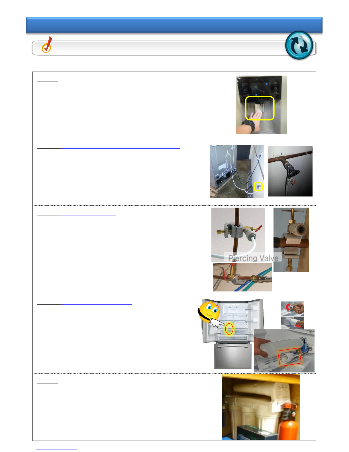
Step 1
① Select Water, then check the water
dispensing when pressing lever.
- When there is no water dispensing Check
Step 2
- When the water is dispensing check TIP 24
Step 2 (Connection problem-Hose kinked)
① Inspect connection between external tap and
the product
- Check if it is connected to water supply
- Check if the tap is closed.
② Check for kinked Water supply line
Step 3 (Piercing Valve )
① Check for water with piercing valve open and
supply hose disconnected.
(Piercing valves are not recommended)
Step 4 (Filter Case problem)
① Remove Water Filter and check dispensing.
If water dispenses ,try a new filter. If
water does not dispense with new filter,
replace the Filter Case.
Step 5
① Minimum water supply pressure should be
20 PSI.
② If pressure is low due to external filter
(reverse osmosis) remove internal filter.
Check Point
Inspect Water supplying failure
Tip 2-1. Inspect water connection/supplying
※ Before first use and after filter replacement, dispense water for 3 min
Piercing Valve
- 9/65 -
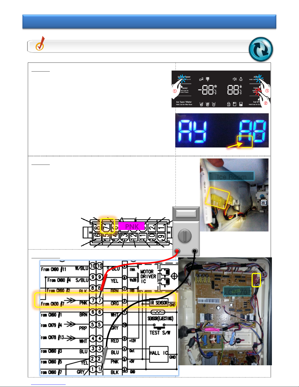
Step 1
① Check the ICE Bucket for the presence of
ice.
② If no ice, Enter After PANEL PBA “Energy
Saver”+”Alarm” Key and touch LED Blink
“Fridge” Key.
③ In the case of FF-Display Yellow Blink
- Recognized Ice Bucket Full Check STEP 2
- When there is no Blink Check Tip 2-3
Step 2
① Inspect the “YEL 16-PIN” CONNECTOR
No.7(PNK) PIN contact/switching
② Inspect Wire connector
- No.7(PNK) + Main PBA CN 30 No.7(PNK)
Main PBA
Check Point
Inspect ice maker Water supply problem
Tip 2-2. Inspect Ice Full sensing failure
CN 70
Ice Room
PNK
- 10/65 -
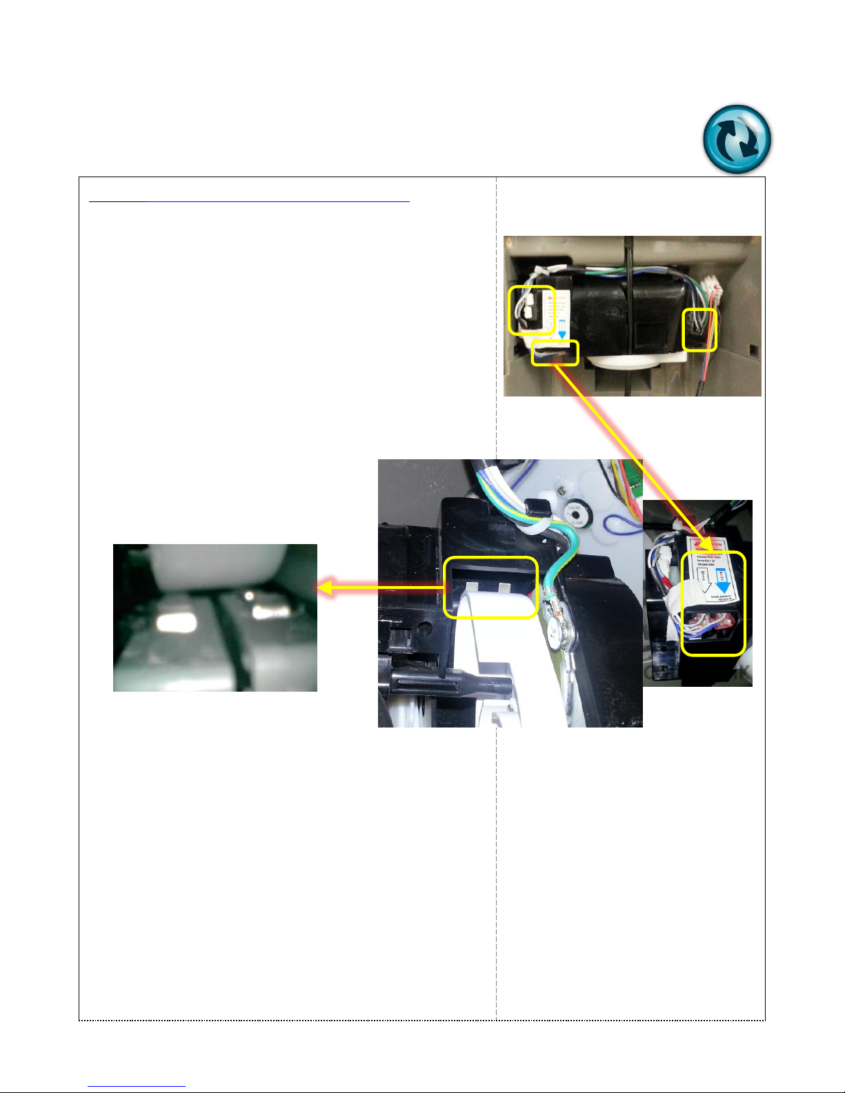
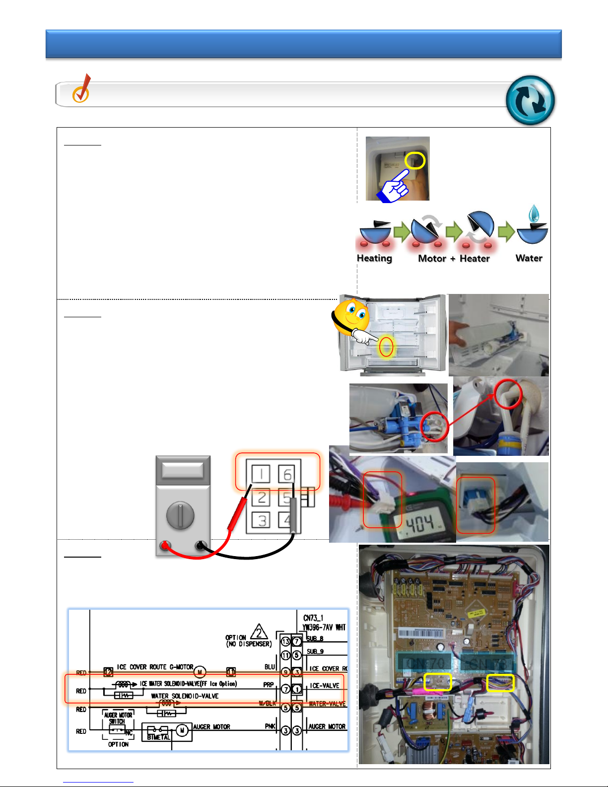
Step 1
① After disassemble the Ice Bucket and ice
maker
Right side button on ice maker turns on for
2 sec
① Takes Max “6 Min” (including Heating
time)
- When the water does not come Check
Step 2
- When the water come Check TIP 2-5
Step 2
① Inspect the WATER HOSE bending
② After disassemble the ASSY Valve, Purple 2
Pin Check
- Normal part : 350~450 Ω
- Failure part : Open or 0 Ω
③ Check the housing No.1(PRP/BLK)
+ No.6(PRP/BLK)
Step 2
① Check MAIN PBA + Liner CONNECTOR
- Check CN70 No.5(RED)+CN73 No.1(PRP)
Check Point
Inspect ICE MAKER Water supply problem
Tip 2-3. Inspect the Ice Valve operation
CN 73
CN 70
- 11/65 -
※ Fan Motor indicates failure in On condition .
Touch the Display “Energy Saver”+Alarm” Key at
the same time for 8 sec.
- After blink All LEDs, touch it until the “chime”
occurs
- Self diagnosis test is normal check TIP 2-5
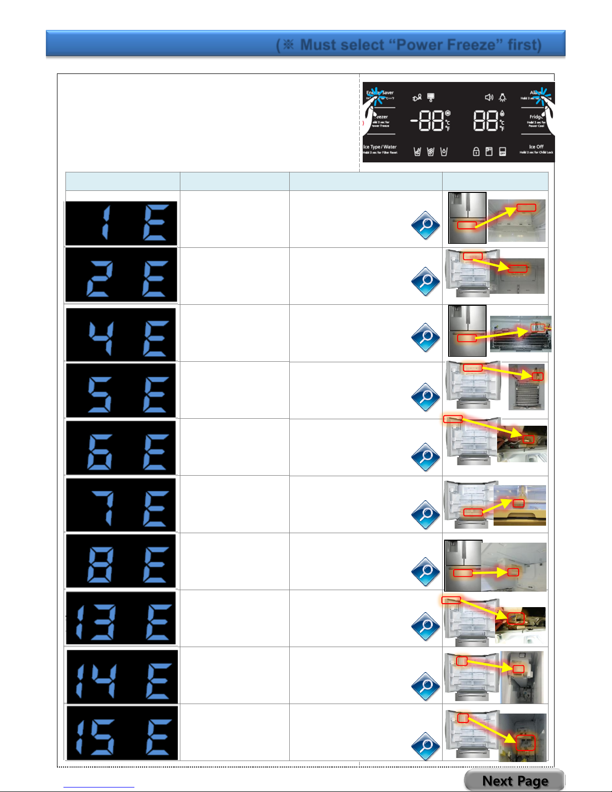
● Inspect self- diagnosis test (※ Must select “Power Freeze” first)
Display (Image)
Error Item
Measure
IMAGE
FZ-Sensor
① FZ-Sensor
② Wire Open Check
FF-Sensor
① FF-Sensor
② Wire Open Check
FZ-DEF-Sensor
① FZ-DEF-Sensor
② Wire Open Check
FF-DEF-Sensor
① FF-DEF-Sensor
② Wire Open Check
Ambient-Sensor
① Ambient-Sensor
② Wire Open Check
Pantry-Sensor
① Pantry-Sensor
② Wire Open Check
Ice Maker(FZ)
-Sensor
① Ice Maker(FZ)-Sensor
② Wire Open Check
Humidity-Sensor
① Humidity-Sensor
② Wire Open Check
Ice Maker(FF)
-Sensor
① Ice Maker(FF)-Sensor
② Wire Open Check
Ice Room(FF)
-Sensor
① Ice Room(FF)-Sensor
② Wire Open Check
Next Page
- 12/65 -
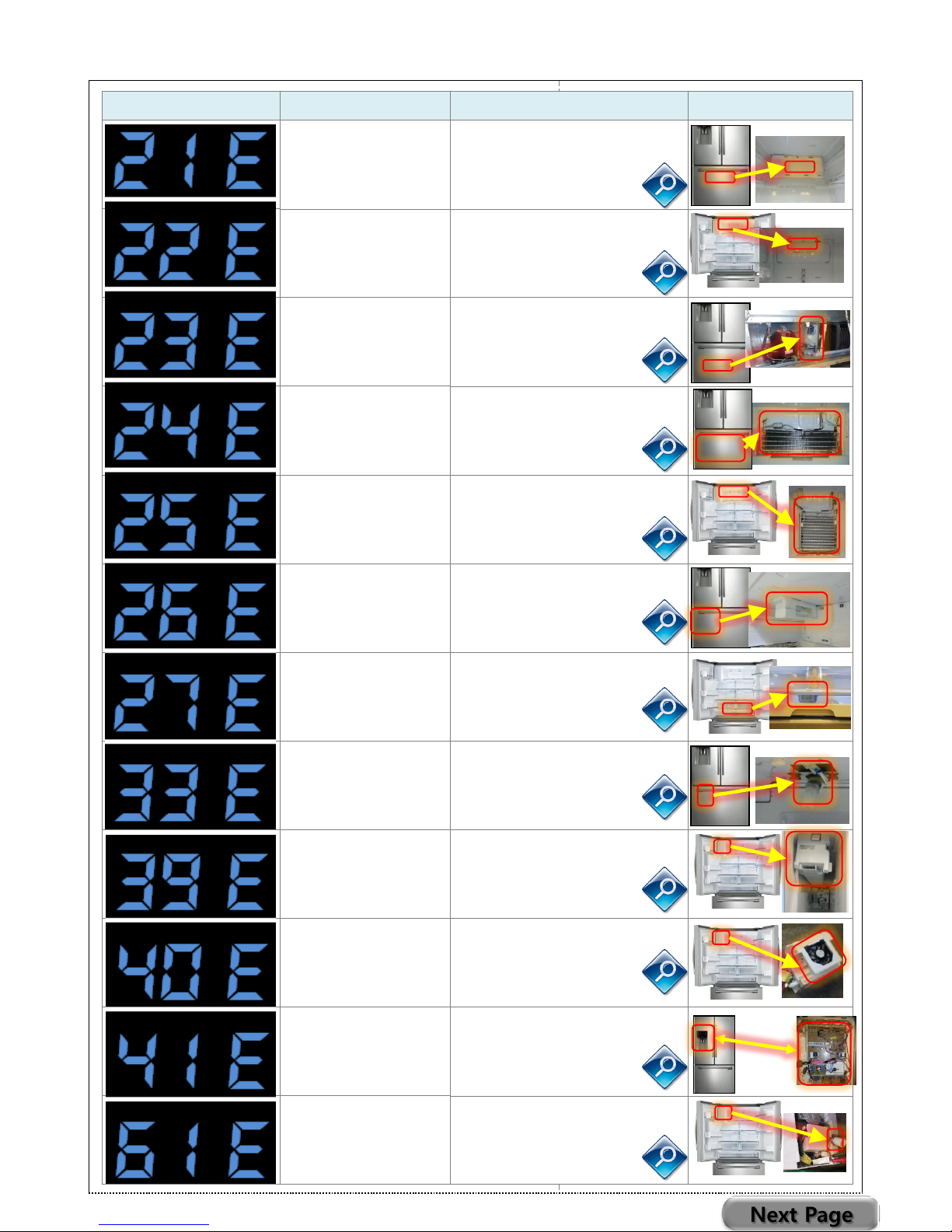
Display (Image)
Error Item
Measure
IMAGE
FZ-Fan Motor
① FZ-Fan Motor FG NG
② Wire Open Check
FF-Fan Motor
① FF-Fan Motor FG NG
② Wire Open Check
C-Fan Motor
① C-Fan Motor FG NG
② Wire Open Check
FZ-DEF-Function
① FZ-Defrost Heater open
② FZ-Defrost Sensor NG
③ Thermo fuse open
④ Wire open check
FF-DEF-Function
① FZ-Defrost Heater open
② FZ-Defrost Sensor NG
③ Thermo fuse open
④ Wire open check
FZ-Ice Maker
-Function
① Ice Maker NG
② Wire Open Check
Pantry Damper
DC Heater
① Pantry Damper DC
Heater Open
② Wire Open Check
FZ-Ice Pipe Heater
① FZ-Ice Pipe DC Heater
Open
② Wire Open Check
FF-Ice Maker
-Function
① Ice Maker Heater Open
② Ice Maker NG
③ Wire Open Check
FF-Ice Room
- Fan Motor
① Ice Fan Motor FG-NG
② Wire Open Check
Panel ↔ Main PBA
Communication
① Panel PBA NG
② Wire Open Check
③ Main PBA
FF-Ice Room Drain
Heater
① FF Ice Room Drain DC
Heater Open
② Wire Open Check
Next Page
- 13/65 -
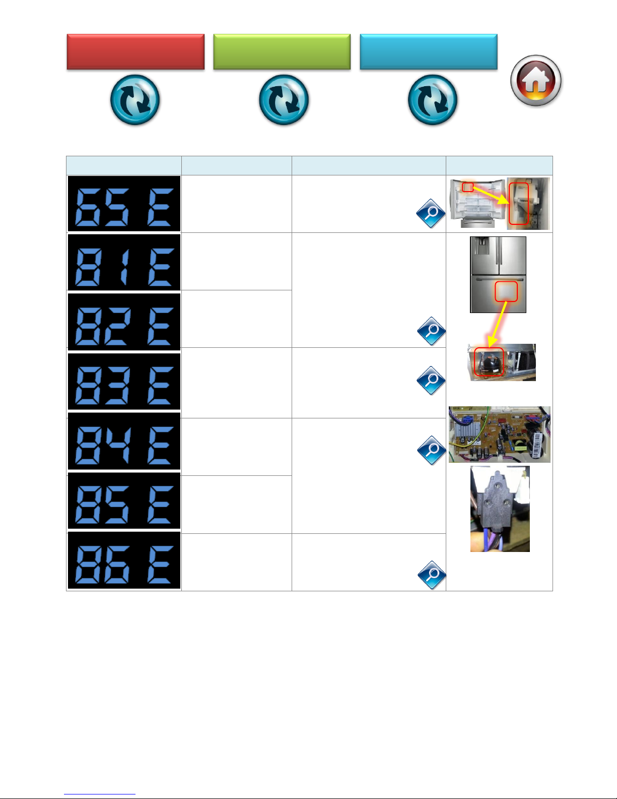
Display (Image)
Error Item
Measure
IMAGE
FF-Ice Room
DC Heater
① FZ-Fan Motor FG NG
② Wire Open Check
Comp Starting
Failure
① Initial re-operation-rest
7min.
② COMP U.V.W상 SHORT
③ IPM PIN SHORT
④ INVERTER PBA failure
Inverter PBA
IPM Fault
Comp Abnormal
current Detection
① Inverter PBA CN04
inspection
- changed/OPEN
② COMP WIRE inspection
- changed/OPEN
Motor Locked Over
RPM
① COMP LOCKED
-CYCLE inspection
② COMP LOW rpm
③ Initial re-operation-rest
7min.
④ INVERTER PBA
Comp under
voltage
Comp over
voltage
① Inspect the outlet power
② INVERTER PBA
Ice Defrost Cooling
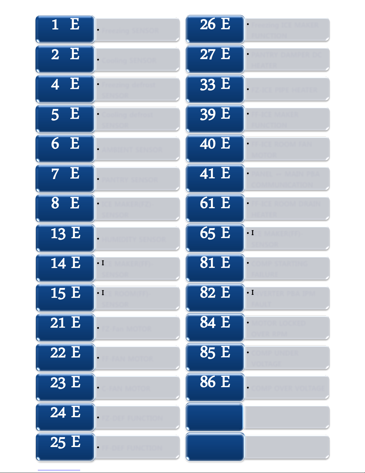
- 14/65 -
• Freezing SENSOR
1 E
• Cooling SENSOR
2 E
• Freezing defrost
SENSOR
4 E
• Cooling defrost
SENSOR
5 E
• AMBIENT SENSOR
6 E
• PANTRY SENSOR
7 E
• ICE MAKER(FZ)-
SENSOR
8 E
• HUMIDITY SENSOR
13 E
• ICE MAKER(FF)-
SENSOR
14 E
• ICE ROOM(FF)-
SENSOR
15 E
• FZ-Fan MOTOR
21 E
• FF-FAN MOTOR
22 E
• C-FAN MOTOR
23 E
• FZ-DEF FUNCTION
24 E
• FF-DEF FUNCTION
25 E
• Freezing ICE MAKER
FUNCTION
26 E
• PANTRY DAMPER DC
HEATER
27 E
• FZ-ICE PIPE HEATER
33 E
• FF-ICE MAKER
FUNCTION
39 E
• FF-ICE ROOM FAN
MOTOR
40 E
• PANEL ↔ MAIN PBA
COMMUNICATION
41 E
• FF-ICE ROOM DRAIN
HEATER
61 E
• ICE MAKER(FF)-
SENSOR
65 E
• COMP STARTING
FAILURE
81 E
• INVERTER PBA IPM
FAULT
82 E
• MOTOR LOCKED
OVER RPM
84 E
• COMP UNDER
VOLTAGE
85 E
• COMP OVER VOLTAGE
86 E
- 15/65 -
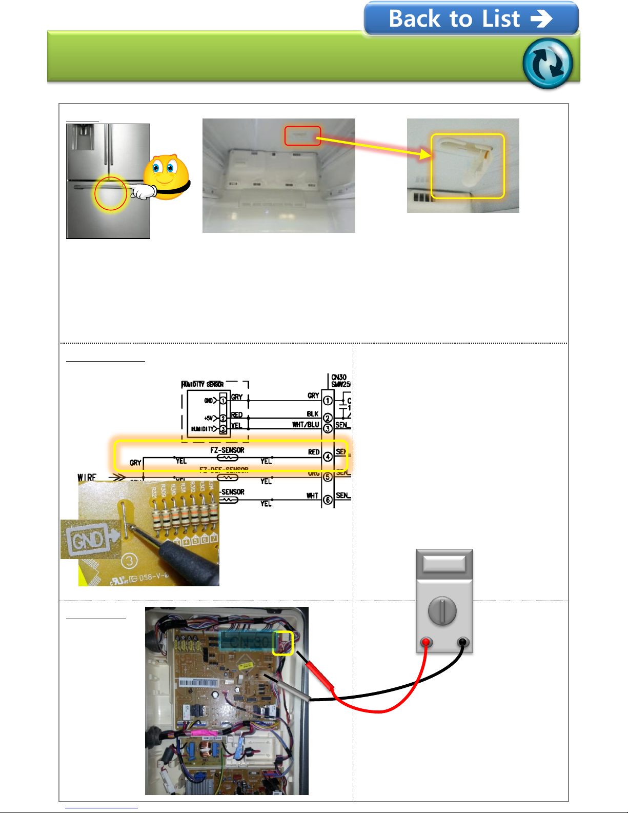
Error-code : 1 E
FZ-Room Sensor Error
Block
① Disassemble the FZ-Room BOX
② After disassemble the Sensor Cover and inspect the Wire Open
③ Measure the Main PBA DC voltage
- Normal : DC 1.2V(100℉) ~ 4.0V(-13℉)
- Failure : DC 1.3V ↓,4V↑ Inspect bottom WIRE
CONNECTOR
① Inspect the Main PBA CN30
No.4(RED)+
PBA “GND” marked area
and DC voltage measuring
- Normal: DC 1.2V(100℉)
~ 4.0V(-13℉)
- Failure : DC 1.3V ↓,4V↑
Main PBA
CN 30
Back to List
- 16/65 -
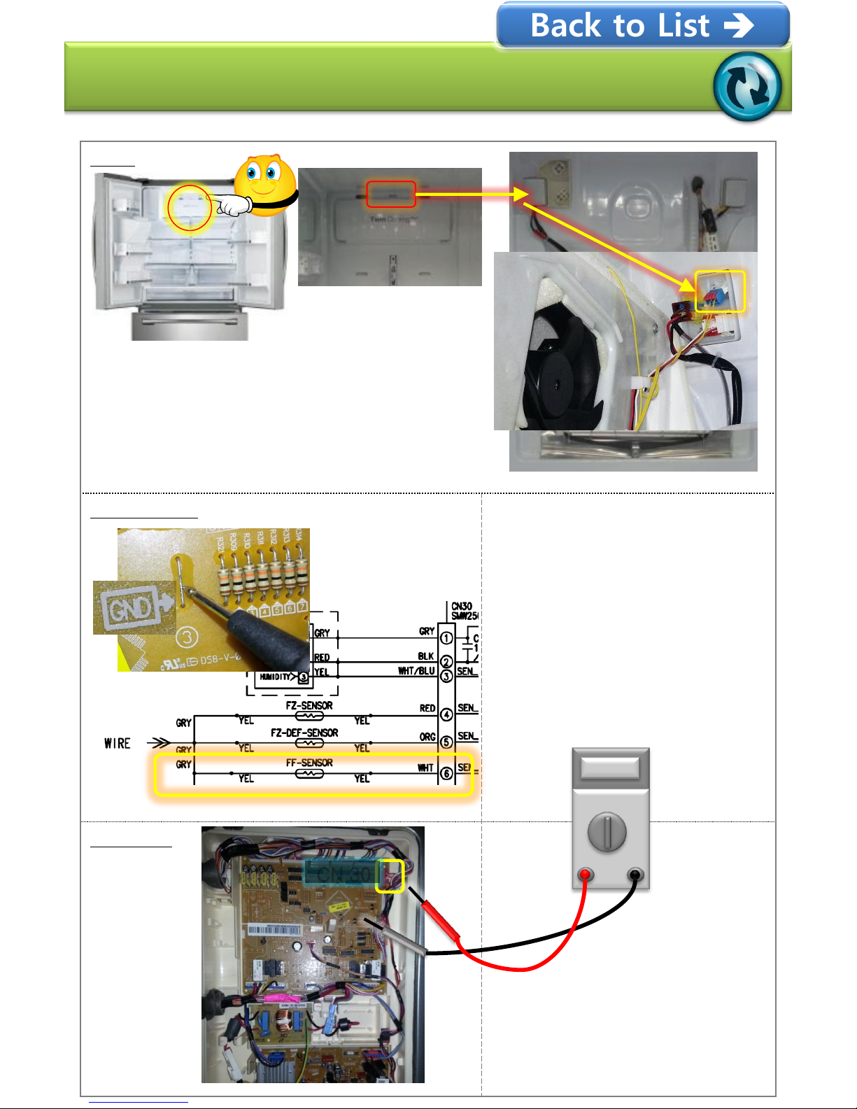
Error-code : 2 E
FF-Room Sensor Error
Block
① Disassemble the FF-Room EVAP COVER
② Inspect the BLUE CONNECTOR(2-WIRE)
③ Measure Main PBA DC voltage
- Normal : DC 1.2V(100℉) ~ 4.0V(-13℉)
- Failure : DC 1.3V ↓,4V↑
Check bottom WIRE
CONNECTOR
① Inspect Main PBA CN30
No.6(WHT)+
PBA “GND” marked area
and DC voltage measuring
- Normal : DC 1.2V(100℉)
~ 4.0V(-13℉)
- Failure : DC 1.3V ↓,4V↑
Main PBA
CN 30
Back to List
- 17/65 -
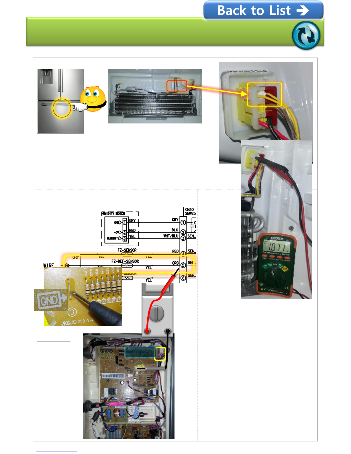
Error-code : 4 E
FZ-Defrost Sensor Error
Block
① After disassemble the EVAP COVER and inspect
Wire Open
② Measure the Liner CONNECTOR DC voltage
- Normal : DC 1.2V(100℉) ~ 4.0V(-13℉)
- Failure : DC 1.3V ↓,4V↑ Inspect the bottom WIRE
CONNECTOR
① Inspect the Main PBA CN30
No.5(ORG)+
PBA “GND” marked area
and DC voltage measuring
- Normal : DC 1.2V(100℉)
~ 4.0V(-13℉)
- Failure : DC 1.3V ↓,4V↑
Main PBA
CN 30
Back to List
- 18/65 -
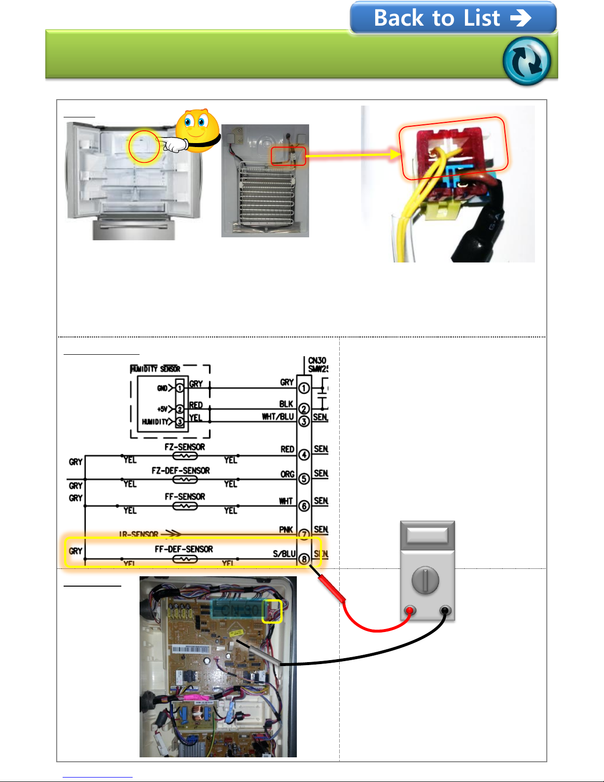
Error-code : 5 E
FF-Defrost Sensor Error
Block
① Disassemble the FF-Room EVAP COVER
② Inspect the YELLOW CONNECTOR(2-WIRE) Open
③ Measure the Main PBA DC voltage
- Normal : DC 1.2V(100℉) ~ 4.0V(-13℉)
- Failure : DC 1.3V ↓,4V↑ Inspect the bottom WIRE
CONNECTOR
① Inspect the Main PBA CN30
No.8(S/BLU)
+ PBA “GND” marked area
and DC voltage measuring
- Normal : DC 1.2V(100℉)
~ 4.0V(-13℉)
- Failure : DC 1.3V ↓,4V↑
Main PBA
CN 30
Back to List
- 19/65 -
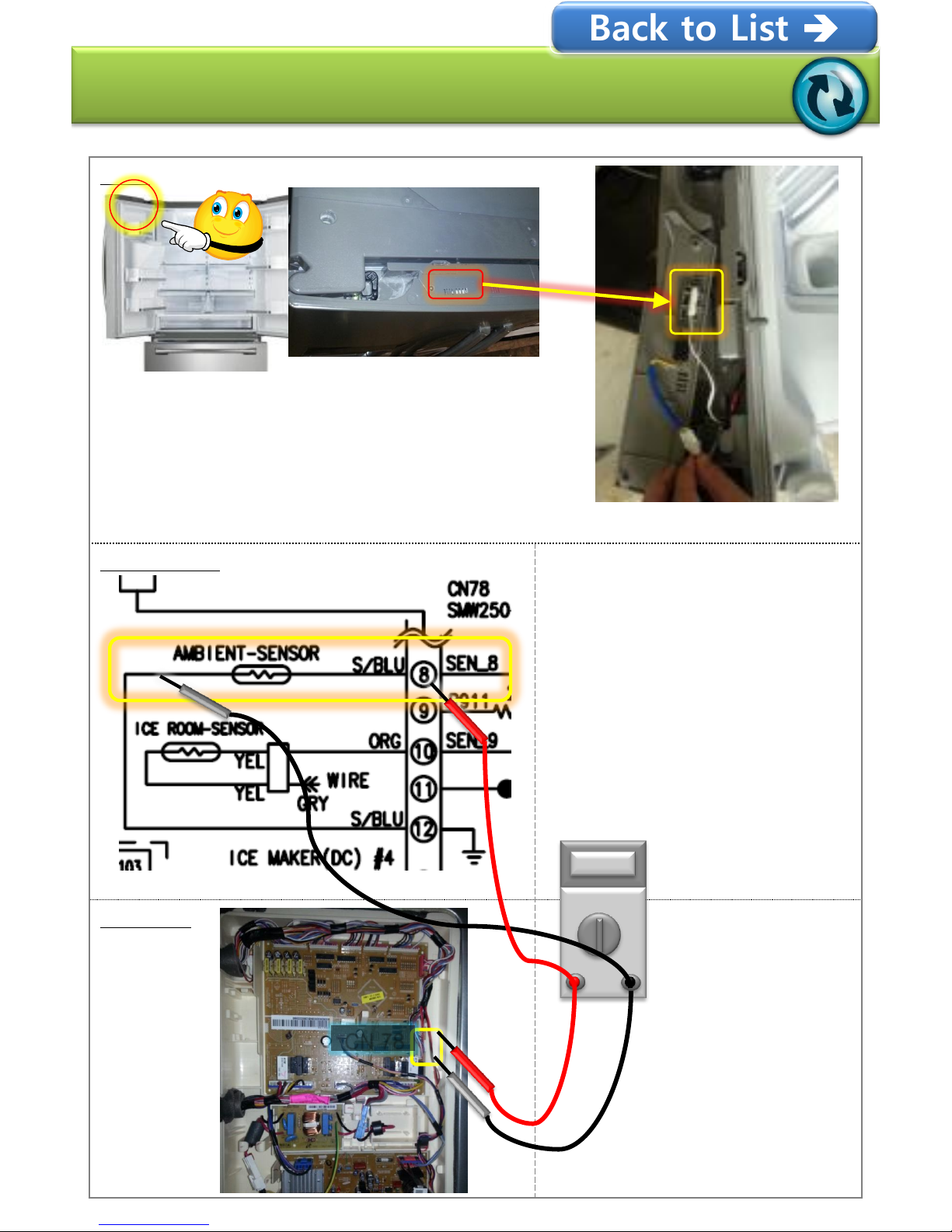
Error-code : 6 E
Ambient- Sensor Error
Block
① Disassemble the FF-DOOR L UPP COVER
② Inspect the WHITE WIRE Open
③ Measure the Main PBA DC voltage
- Normal : DC 1.2V(100℉) ~ 4.0V(-13℉)
- Failure : DC 1.3V ↓,4V↑
Inspect the bottom WIRE
CONNECTOR
① Inspect the Main PBA CN78
No.8(S/BLU)
+ No.12(S/BLU)
DC voltage measuring
- Normal : DC 1.2V(100℉)
~ 4.0V(-13℉)
- Failure : DC 1.3V ↓,4V↑
Main PBA
CN 78
Back to List
- 20/65 -
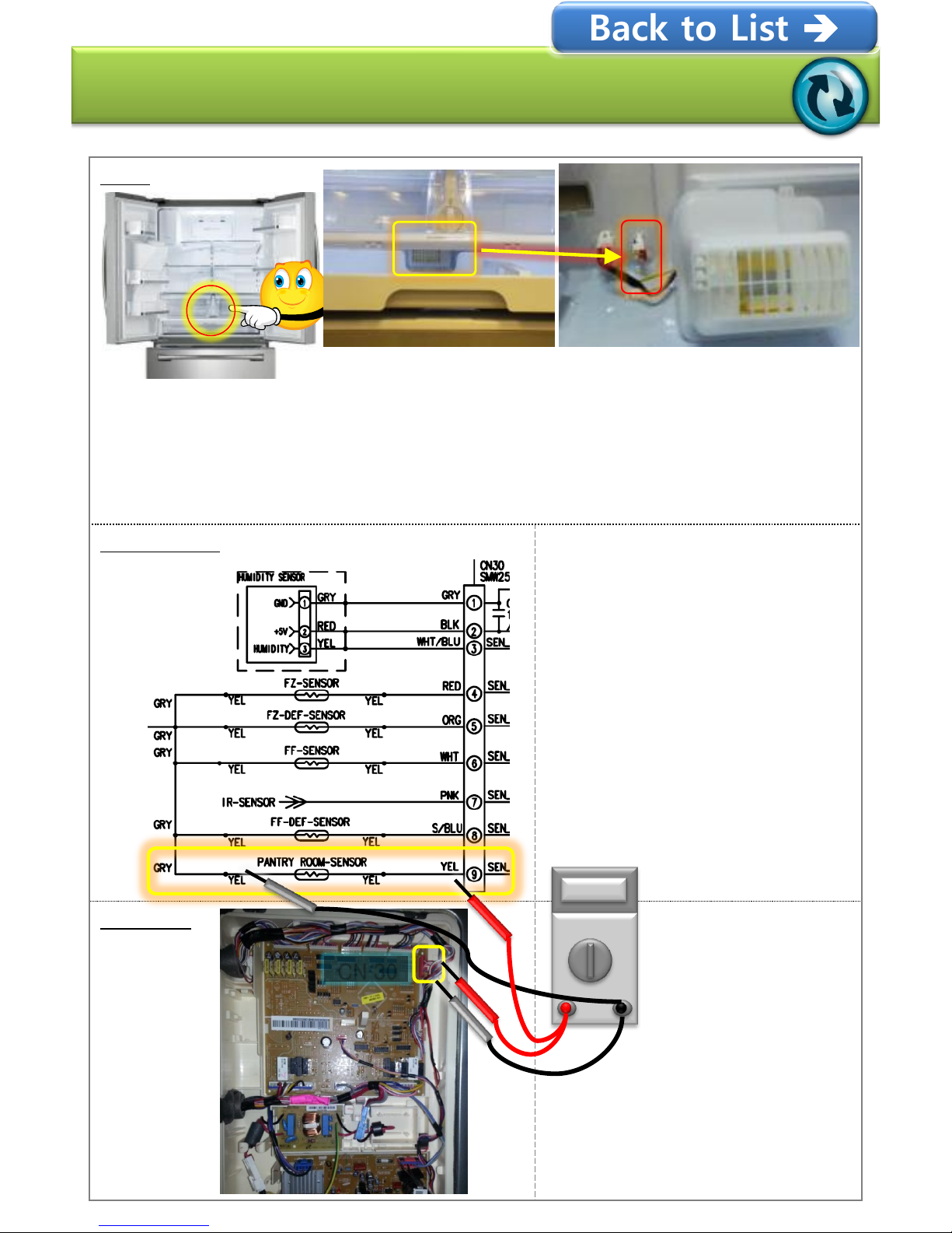
Error-code : 7 E
Pantry Sensor Error
Block
① Disassemble the VEG BOX and Pantry
② Inspect the Yellow 2-WIRE CONNECTOR
③ Measure the Main PBA DC voltage
- Normal : DC 1.2V(100℉) ~ 4.0V(-13℉)
- Failure : DC 1.3V ↓,4V↑ Inspect the bottom WIRE
CONNECTOR
① Inspect the Main PBA CN30
No.9(YEL)+
PBA “GND” marked area
and DC voltage measuring
- Normal : DC 1.2V(100℉)
~ 4.0V(-13℉)
- Failure : DC 1.3V ↓,4V↑
② Inspect the same Liner part
CONNECTOR
DC voltage measuring
- Normal : DC 1.2V(100℉)
~ 4.0V(-13℉)
- Failure : DC 1.3V ↓,4V↑
Main PBA
CN 30
Back to List

- 21/65 -
Error-code : 8 E
Ice Maker(FZ) Sensor Error
Block
① Disassemble the BOX
② Inspect the Ice Maker Bottom Sensor /
Wire OPEN
③ Measure Main PBA CN90 No.8+No.9 DC voltage
- Normal : DC 1.2V(100℉) ~ 4.0V(-13℉)
- Failure : DC 1.3V ↓,4V↑ Inspect the bottom WIRE
CONNECTOR
① Inspect Main PBA CN90
No.8(WHT)+
No.9(RED) DC voltage
measuring
- Normal : DC 1.2V(100℉)
~ 4.0V(-13℉)
- Failure : DC 1.3V ↓,4V↑
② Inspect Liner part
CONNECTOR No.5+CN90
No.9(RED)
Liner part CONNECTOR
No.6+CN90 No.8(WHT)
WIRE OPEN
Main PBA
CN 90
Back to List
 Loading...