

Samsung RES 3.6 kWh All In One, ELSR362-00004 User Manual
Australia (Eng.) 05/2015. Rev1.1
User Manual
RES 3.6 kWh All In One
CAUTION
Do not operate with other components not approved by the ESS systems.
(Connecting other products in parallel to Samsung SDI's products may result in
abnormal operation.)
The internet connection is required to use all functions of the ESS system.
If you have a problem, please contact the installer.
The Specications of the product may be modied without prior notice to improve
product qu
ality.
ELSR362-00004

Table of Contents
Table of Contents
Table of Contents ......................................................................................................... i
Table of Tables ............................................................................................................ iii
Table of Figures .......................................................................................................... iv
1. Information in this Manual .................................................................................... 1
1.1 About this Manual .................................................................................................................................... 1
1.2 Target Group .............................................................................................................................................. 1
1.3 Additional Information ........................................................................................................................... 1
1.4 Symbols Used ............................................................................................................................................ 1
2. Safety ...................................................................................................................... 5
2.1 Intended Use .............................................................................................................................................. 5
2.1.1 Installation Application Suitable for Safety ........................................................................ 7
2.1.2 Technical Specifications ............................................................................................................ 9
2.2 Safety Guidelines ................................................................................................................................... 13
2.3 Symbol Indication ................................................................................................................................. 14
3. Product Overview ................................................................................................ 15
4. Operating Modes ................................................................................................. 16
4.1 Descriptions of Operation Mode ...................................................................................................... 16
4.1.1 PV-Auto Mode ........................................................................................................................... 16
4.1.2 PV-Only Mode ........................................................................................................................... 17
4.1.3 Battery-Discharge Mode ........................................................................................................ 18
4.1.4 Standby Mode........................................................................................................................... 18
4.1.5 Forced-Charge Mode (Maintenance mode) .................................................................... 19
4.1.6 Stand-Alone Mode .................................................................................................................. 19
4.1.7 Event Check Mode ................................................................................................................... 20
4.1.8 Application Download Mode ............................................................................................... 24
4.2 Starting the System............................................................................................................................... 25
4.2.1 Turning off the System ........................................................................................................... 25
5. Communication ................................................................................................... 26
5.1 Overview .................................................................................................................................................. 26
5.2 Components and LAN Connection .................................................................................................. 26
5.2.1 Essential Components ............................................................................................................ 26
5.2.2 LAN Connection ....................................................................................................................... 26
5.3 Homepage ............................................................................................................................................... 27
Australia (Eng.) 05/2015. Rev1.1 i

Table of Contents
5.3.1
Service Terms............................................................................................................................. 27
5.3.2 Membership .............................................................................................................................. 27
5.3.3 Membership Withdrawal ....................................................................................................... 29
5.3.4 Log-In........................................................................................................................................... 29
5.3.5 Password Initialization ............................................................................................................ 30
5.3.6 Types of Service Offered ........................................................................................................ 30
5.3.7 Mobile Service .......................................................................................................................... 33
6. Maintenance for Problem Solving ...................................................................... 34
6.1 Fan Exchange .......................................................................................................................................... 34
6.2 Cleaning ................................................................................................................................................... 35
6.2.1 Cleaning the Side Cover......................................................................................................... 35
6.3 Checking the Event Logs ..................................................................................................................... 36
6.4 Checking the Terminals ....................................................................................................................... 36
7. Message Description ........................................................................................... 37
7.1 Messages in Normal Operation ......................................................................................................... 37
7.2 General Events ........................................................................................................................................ 38
7.2.1 INVERTER General Events (Warnings) ................................................................................ 38
7.2.2 INVERTER General Events (Protection) .............................................................................. 39
7.2.3 Battery Discharge General Events ...................................................................................... 41
7.2.4 PV General Events (Protection) ............................................................................................ 43
7.2.5 System General Events (Protection) ................................................................................... 44
7.2.6 BMS General Events ................................................................................................................ 45
7.2.7 EMS/Communication Events ................................................................................................ 47
7.2.8 Single Fault Events ................................................................................................................... 47
7.3 Significant Events .................................................................................................................................. 48
8. Arrangement of Terms ........................................................................................ 50
9. Contact ................................................................................................................. 51
ii Australia (Eng.) 05/2015. Rev1.1

Table of Tables
Table of Tables
[Table 1-1: Symbol Description] .................................................................................................................... 4
[Table 2-1: Technical Specifications] ............................................................................................................ 9
[Table 2-2: Inverter symbols] ....................................................................................................................... 14
[Table 3-1: Part Description] ........................................................................................................................ 15
[Table 7-1: Message List] ............................................................................................................................... 37
[Table 7-2: Inverter general events warning list] ................................................................................... 39
[Table 7-3: Inverter protection list] ............................................................................................................ 41
[Table 7-4: Battery operation general events list .................................................................................. 43
[Table 7-5: PV general events protection list] ........................................................................................ 44
[Table 7-6: System general events protection list] ............................................................................... 45
[Table 7-7: BMS general events list] .......................................................................................................... 47
[Table 7-8: EMS/communication events list] .......................................................................................... 47
[Table 7-9: Single fault events list] ............................................................................................................. 48
[Table 7-10: Significant events list] ............................................................................................................ 49
Australia (Eng.) 05/2015. Rev1.1 iii

Table of Figures
Table of Figures
[Figure 2-1: Electrical connections] .............................................................................................................. 5
[Figure 2-2: Name Plate] .................................................................................................................................. 7
[Figure 2-3: PV connections] ........................................................................................................................... 8
[Figure 2-4: Distribution box connection diagram]................................................................................. 8
[Figure 2-5: Derating Curve] ........................................................................................................................ 11
[Figure 2-6: Power efficiency curve of System] ...................................................................................... 11
[Figure 2-7: Power efficiency curve of PV Generation] ........................................................................ 12
[Figure 3-1: Part View of Samsung All in One] ....................................................................................... 15
[Figure 4-1: Front status indication screen] ............................................................................................ 16
[Figure 4-2: PV generation, battery charge, Load use, sell remaining amount] .......................... 17
[Figure 4-3: PV generation, battery discharge, Load use, buy shortage amount] ...................... 17
[Figure 4-4: PV generation, Battery standby, Load use, sell remaining amount] ........................ 17
[Figure 4-5: PV generation, Sell remaining amount] ............................................................................ 17
[Figure 4-6: PV generation, Buy shortage amount] .............................................................................. 18
[Figure 4-7: Battery discharge, Load use] ................................................................................................ 18
[Figure 4-8: Battery discharge, Load use, Buy shortage amount] .................................................... 18
[Figure 4-9: Indication screen on Standby Mode]................................................................................. 19
[Figure 4-10: Indication screen on Forced charged Mode] ................................................................ 19
[Figure 4-11: Indication screen on stand-alone mode] ....................................................................... 19
[Figure 4-12: Event occurrence, Grid RMS over current protection] ............................................... 20
[Figure 4-13: Event occurrence, DC link over voltage protection] ................................................... 20
[Figure 4-14: Event occurrence, PV string1 reverse connection protection] ................................ 20
[Figure 4-15: Event occurrence, PV string2 reverse connection protection] ................................ 20
[Figure 4-16: Event occurrence, PV string1 over voltage protection] ............................................. 21
[Figure 4-17: Event occurrence, PV string1 over current protection] ............................................. 21
[Figure 4-18: Event occurrence, PV string2 over voltage protection] ............................................. 21
[Figure 4-19: Event occurrence, PV string2 over current protection] ............................................. 21
[Figure 4-20: Event occurrence, Battery over voltage protection] .................................................. 21
[Figure 4-21: Event occurrence, Battery over current protection] ................................................... 22
[Figure 4-22: Event occurrence, On sequence Inverter DC link event] ........................................... 22
[Figure 4-23: Event occurrence, On sequence Battery V/I event] .................................................... 22
[Figure 4-24: Event occurrence, Normal Inverter DC link event] ...................................................... 22
[Figure 4-25: Event occurrence, Normal Battery V/I & BDC DC link event].................................... 22
[Figure 4-26: Event occurrence, On sequence Inverter DC link event] ........................................... 23
[Figure 4-27: Event occurrence, Normal Inverter DC link & PV I event] .......................................... 23
[Figure 4-28: Event occurrence, Temperature protection] ................................................................ 23
[Figure 4-29: Event occurrence, Over Current TZ Fault]...................................................................... 23
[Figure 4-30: Events occurrence, temperature sensor connection error] ..................................... 23
[Figure 4-31: Event occurrence, PV mis-wiring] ..................................................................................... 24
[Figure 4-32: Event occurrence, SPI communication event] ............................................................. 24
[Figure 4-33: Event occurrence, Single fault event] ............................................................................. 24
[Figure 4-34: Event occurrence, Continuously 3 times Inverter fault] ............................................ 24
[Figure 4-35: Indication screen on Application Download Mode] .................................................. 24
[Figure 4-36: Initial indication screen on power on] ............................................................................ 25
[Figure 4-37: Standby state indication screen before the EMS command] .................................. 25
[Figure 5-1: Communication terminal] ..................................................................................................... 26
[Figure 5-2: Connecting to the website] .................................................................................................. 28
iv Australia (Eng.) 05/2015. Rev1.1

Table of Figures
[Figure 5-3: Entering the information to sign up for a membership] ............................................. 28
[Figure 5-4: Log-in page] .............................................................................................................................. 29
[Figure 5-5: Password initialization page] ............................................................................................... 30
[Figure 5-6: Monitoring page] ..................................................................................................................... 31
[Figure 5-7: Consumption report page] ................................................................................................... 31
[Figure 5-8: Forecast page] .......................................................................................................................... 32
[Figure 5-9: Mobile service page] ............................................................................................................... 33
[Figure 6-1: Side cover removal]................................................................................................................. 34
[Figure 6-2: Fan removal] .............................................................................................................................. 34
[Figure 6-3: Side cover removal]................................................................................................................. 35
Australia (Eng.) 05/2015. Rev1.1 v

Information in this Manual
1. Information in this Manual
1.1 About this Manual
This is the user’s manual for the Samsung 3.6 kWh All in One. This user manual is specially
designed to detail the device
’s functions and features. Please read this manual before using
the device to ensure safe and proper use.
1.2 Target Group
This user manual applies only to the Samsung 3.6 kWh All in One.
1.3 Additional Information
The user manual and installation manual can be downloaded from the product download
section at “https://myess.samsungsdi.com”. The specifications of the product can be
changed for improvement without notice.
Also, the software can be updated automatically without notice over the Internet.
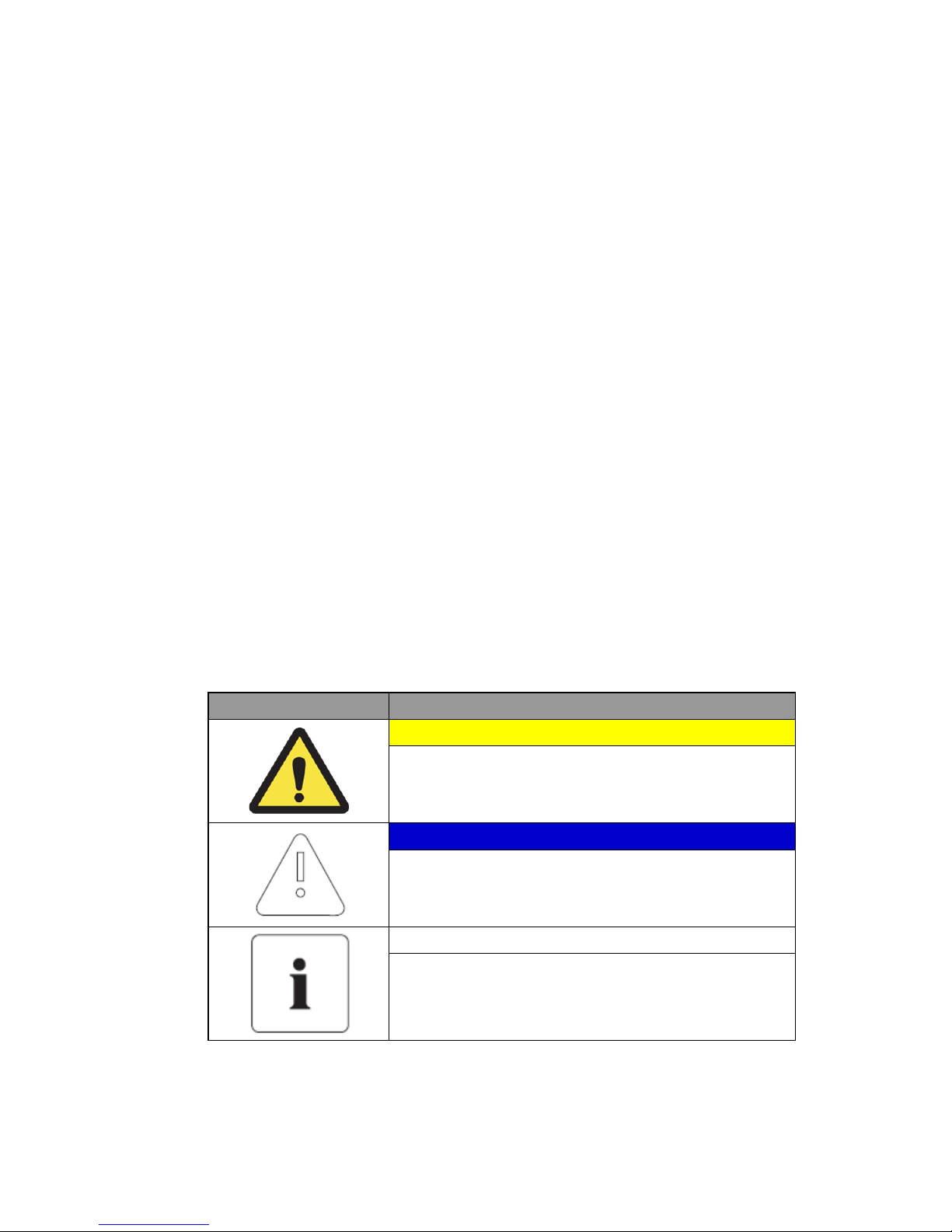
1.4 Symbols Used
Symbols Meaning
CAUTION
This symbol indicates a hazardous situation which could
result in a light injury, if not avoided.
NOTICE
This symbol indicates a hazardous situation which could
result in damage to the property, if not avoided.
Information
This symbol indicates valuable tips for optimum installation
and operation of the product.
Australia (Eng.) 05/2015. Rev1.1 1

Information in this Manual
Symbols Meaning
Beware dangerous voltage.
The inverter operates at high voltage. All works related to the
inverter can only be performed by an electrical technician.
Beware of hot surface.
The inverter can become hot during operation.
Avoid contact during operation.
Follow the guidelines in all relevant documents enclosed
along with the inverter.
Do not dispose of the inverter with household wastes.
For further information on disposal, refer to the installation
manual provided.
The CE Indication:
The relevant equipment complies with the requirements in
the EC guidelines.
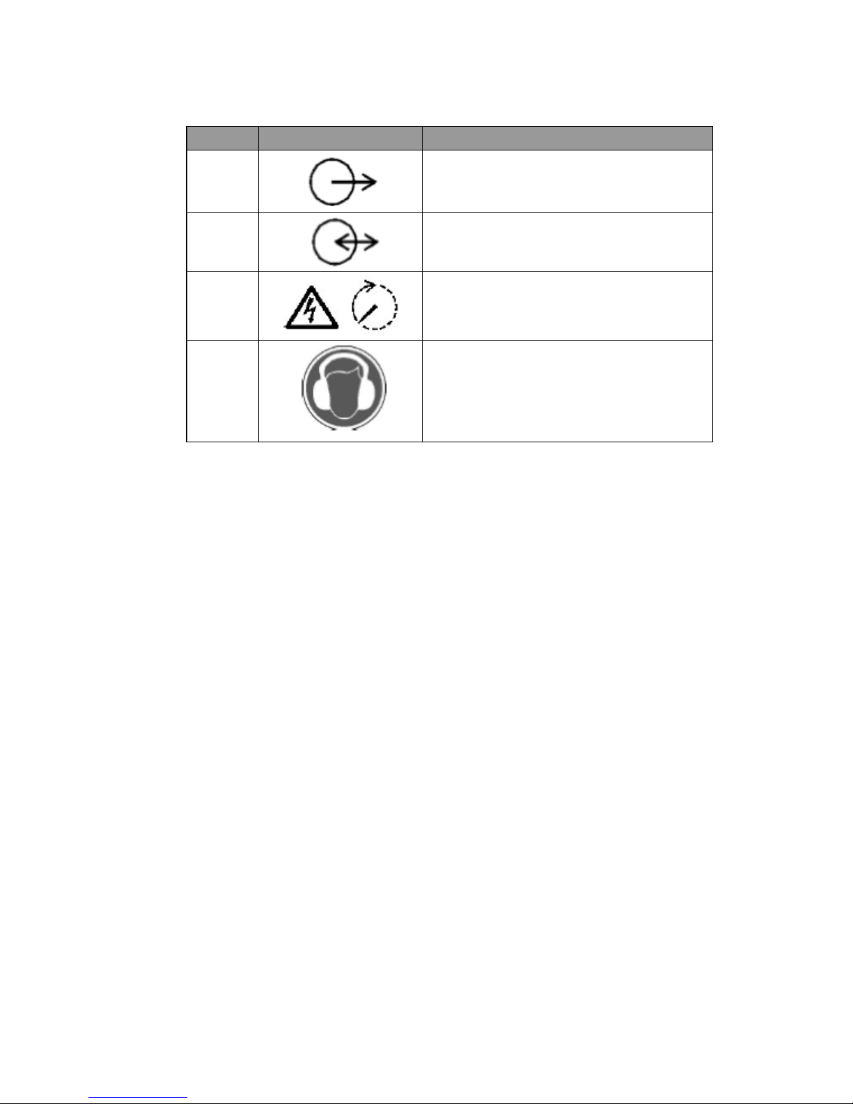
Number Symbol Description
1
Direct current
2
Alternating current
3
Both direct and alternating current
4
Three-phase alternating current
2 Australia (Eng.) 05/2015. Rev1.1
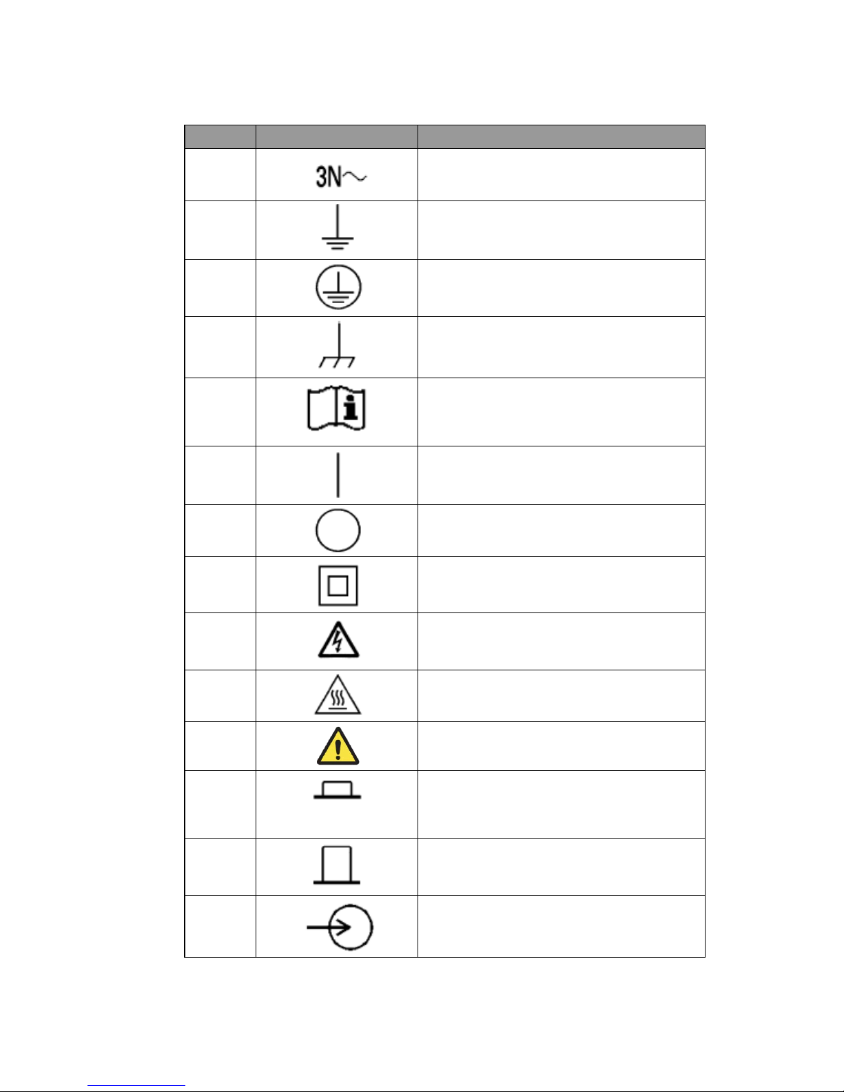
Information in this Manual
Number Symbol Description
5
Three-phase alternating current with neutral
conductor
6
Earth terminal
7
Protective conductor terminal
8
Frame or chassis terminal
9
Refer to the operating instructions
10
On (supply)
11
Off (supply)
12
Equipment protected throughout by double
insulation or reinforced insulation
13
Caution: Risk of Electric Shock
14
Caution: Hot Surface
15
Caution: Risk of Danger
16
In position of a bi-stable push control
17
Out position of a bi-stable push control
18
Input terminal or rating
Australia (Eng.) 05/2015. Rev1.1 3
Information in this Manual
Number Symbol Description
19
Output terminal or rating
20
Bidirectional terminal rating
21
Caution: Risk of Electric Shock and Energy
Storage Timed Discharge
22
Caution: Risk of Hearing Damage and Wear
Hearing Protection Wear hearing protection
[Table 1-1: Symbol Description]
4 Australia (Eng.) 05/2015. Rev1.1
Safety
2. Safety
2.1 Intended Use
NOTICE
The 3.6 kWh All in One system is intended for residential use only.
The 3.6 kWh All in One system should not be used for commercial or
building.
The original usage purpose of this device is for household single-phase system link solar
energy generation and Li-Ion Battery charge and discharge. The basic operations are as
follows.
Samsung 3.6 kWh All In One uses solar energy power connected to the input/output
terminal installed on the side of the device to charge the Li-Ion Battery installed inside, and
converts the direct current electricity of the battery to alternating current to discharge as
household single-phase load or electric system, or uses the electric system of electric energy
to charge the battery.
This device should not be used for any purpose other than the purpose described in this
User manual. Any substitute use of this device, random change in any of its parts, and use of
components other than sold or recommended by Samsung SDI will nullify the product's
guarantee. For further information on proper use of this device, contact the Samsung SDI
Service line or visit at “www.samsungsdi.com”.
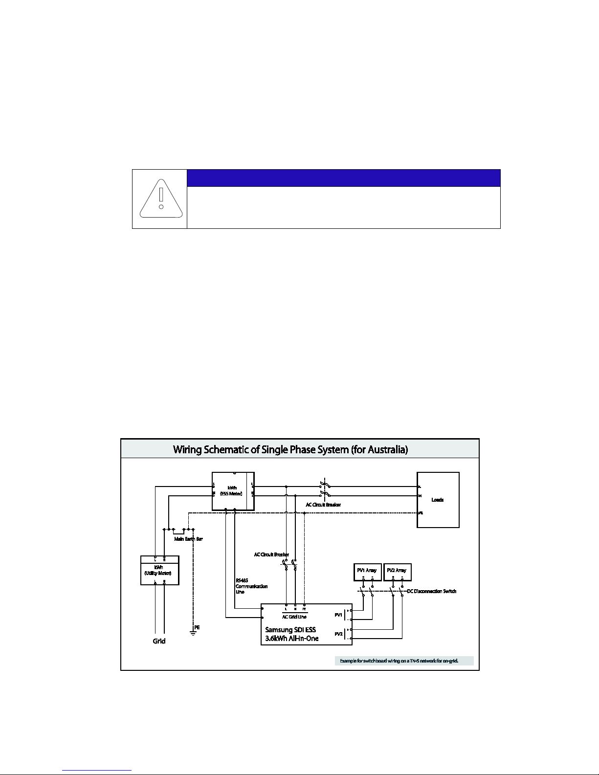
[Figure 2-1: Electrical connections]
Australia (Eng.) 05/2015. Rev1.1 5

Safety
Identifying the Product
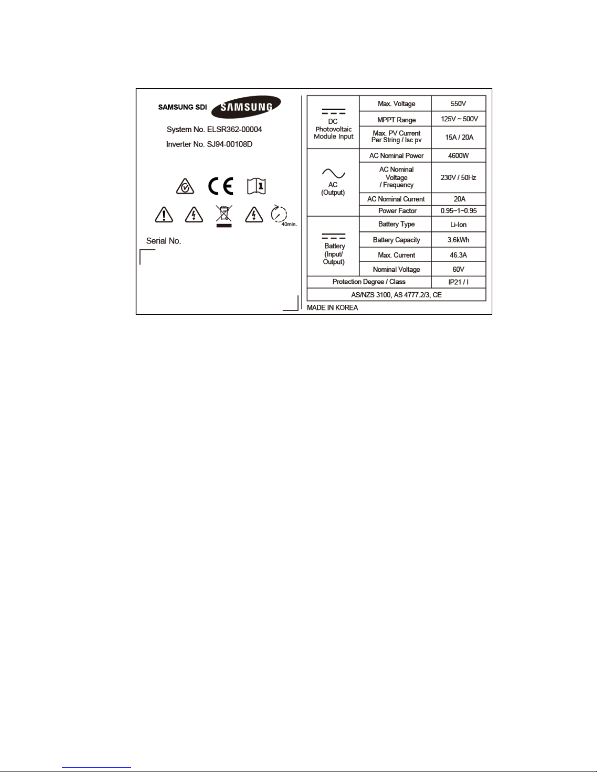
Attached on the enclosure of this product is the Type Label where the identity of this
product is described. For safe usage, make sure that the following product information is
indicated on the Type Label.
■ Product Name
■ Device Type (Model)
■ Serial Number (Serial No.)
■ Device-specific characteristics
■ Certification Lists
■ Warnings and Notification
The model No. of 3.6 kWh All In One system is defined as below.
■ ELSR362-00004
• ELSR: Residential application
• 36: Battery capacity (x0.1kWh)
• 2: Battery capacity group (Less than 10kW)
• 00004: product line number
The model No. of INVERTER (power conditioning system) is defined as below.
■ SJ94-00108D
• SJ: battery for ESS
• 94: Ass’y
• 00108: product number
• D: National Code (Australia)
The Type Label is shown in the [Figure 2-2].
6 Australia (Eng.) 05/2015. Rev1.1
Safety
[Figure 2-2: Name Plate]
2.1.1 Installation Application Suitable for Safety
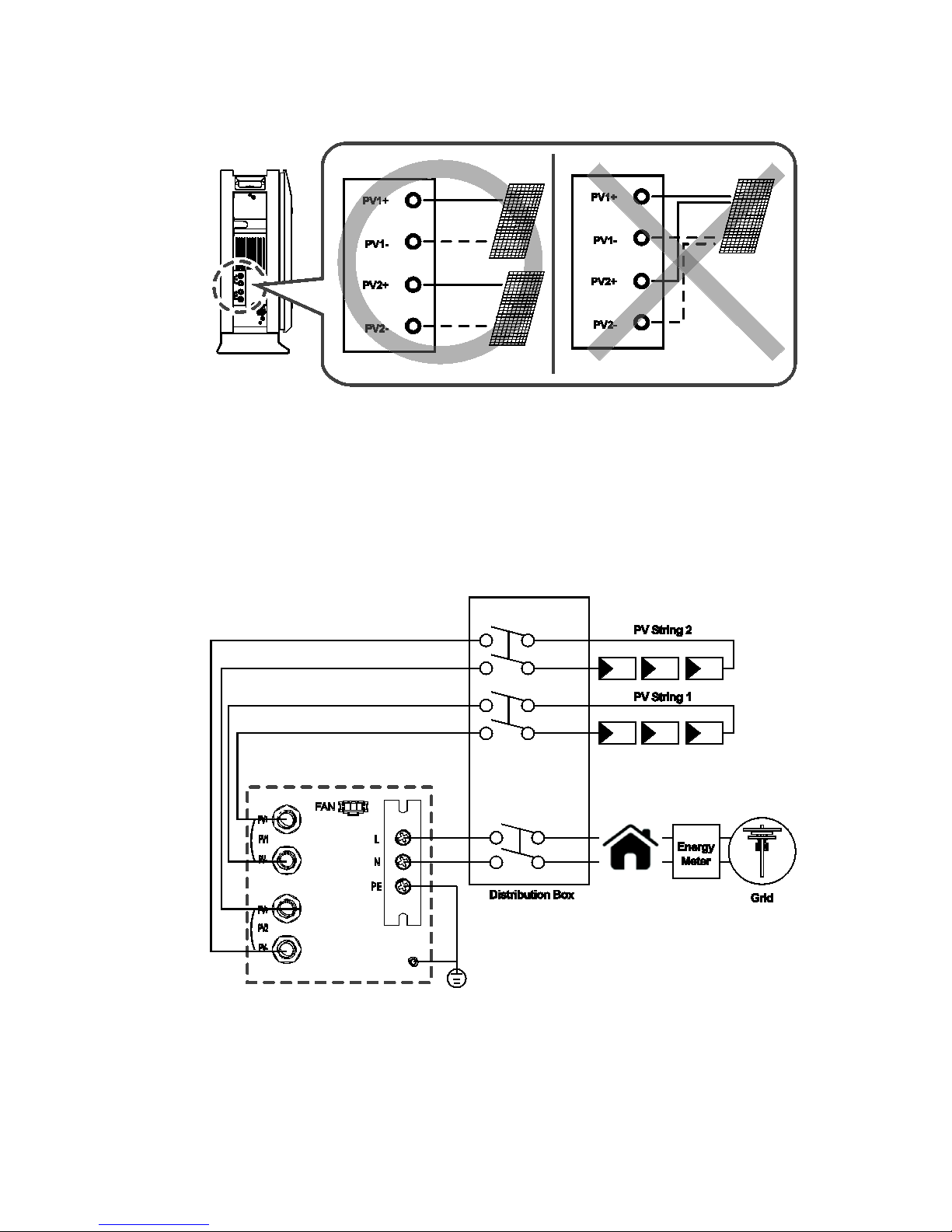
This device, Samsung RES 3.6 kWh All in One, is designed to be suitable for household
purposes. The PV Input terminal is composed of two Strings. One PV String input must install
3.3 kW or less PV panel capacity, and the maximum input voltage of the PV String must be
limited to 550V or less.
As shown in the [Figure 2-3], the 3.6 kWh All In One uses the two independent channels of
the PV Input ({PV1+, PV1-}, {PV2+, PV2-}). They are used independently for running the
maximum power from the sources of PV1 and PV2. Two channels are recommended for
independent use for the two PV Inputs. Make sure not to connect one PV string in parallel
with the two independent PV inputs (PV1, PV2). (Refer to 3.6 kWh All In One Solar energy
input connection in the [Figure 2-3]). PV common mode is not allowed.
※ PV modules shall have an IEC61730 Application Class A rating or equivalent.
Australia (Eng.) 05/2015. Rev1.1 7
Safety
[Figure 2-3: PV connections]
To connect 3.6 kWh All In One with the Public Grid, make sure to install the watt-hour meter
recommended by Samsung SDI (refer to the installation manual) and to install the
distribution box between 3.6 kWh All In One and the Grid watt-hour meter. Before installing
the distribution box, select a suitable location complying with the IP21 and use the
equipment recommended by the installation company. Please note that failure to do so may
cause malfunction and the product will not be guaranteed for any accident or damage.
Refer to the installation manual for further information. The [Figure 2-4] shows the complete
connection line as described so far.
[Figure 2-4: Distribution box connection diagram]
8 Australia (Eng.) 05/2015. Rev1.1
Safety
2.1.2 Technical Specifications
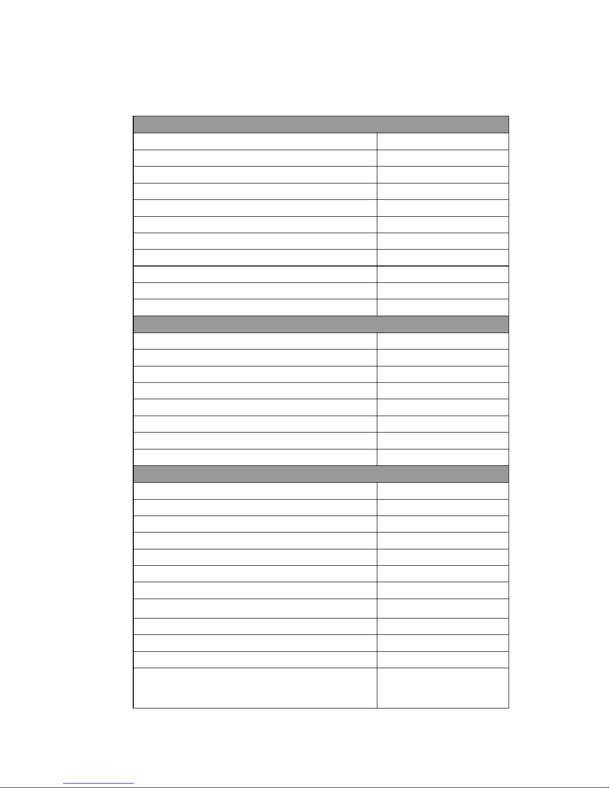
PV Data (DC)
Max. input total power 6.6 kWp
Max. input power per string 3.3 kWp
Max. input voltage 550 V
Min. input voltage/Initial input voltage 125 V/150 V
MPPT voltage range 125 V~500 V
Max. input current per string 15 A
Max. input short circuit current for each MPPT 20 A
Max. inverter backfeed current to the array Negligible
Number of independent MPPT trackers 2
Number of DC inputs pairs for each MPPT 2
Connection type MC4
Battery Data (DC)
Battery capacity 3.6 kWh
Battery voltage range/nominal voltage 48.0 V~65.9 V/60 V
Battery Max. current 46.3 A
Battery nominal current 33.3 A
Discharge of depth 90% (6000 cycles)
Battery technology Li-Ion
Nominal DC/DC power 2.0 kW
DC/DC converter technology Isolated
Grid Data (AC)
Rated power (at 230V, 50 Hz) 4.6 kW
Max. apparent power 5 kVA
Nominal voltage/range 230 V/184 V~264 V
Rated power frequency/range 50 Hz/47.5 Hz~51.5 Hz
Max. current 20 A
Max. over-current protection 30 A
Max. allowed current for fuse protection 32 A
Inrush current
68.6 A (peak), 100 μs
Max. output fault current 420 A (peak), 4 ms
Adjustable power factor range 0.95~1~0.95
Feed-in phases/connection phases 1/1
Total Harmonic Distortion.
(Total harmonic factor of the output current with total
harmonic factor of the AC voltage < 2%,
5%
Australia (Eng.) 05/2015. Rev1.1 9
Safety
and AC power > 50% of the rated power)
Efficiency (PV to Grid)
European efficiency 95 %
Max. efficiency 95.5 %
Protective Device
DC disconnection device for PV No
Ground-fault monitoring/grid monitoring Yes/Yes
General Data
Dimensions (W/H/D) 1000/680/267 mm
Weight 95 kg
Protective class (I, II, III) Class I
Degree of protection IP21
Max. permissible value for relative humidity 95 % (non-condensing)
Operating temperature -10~40°C
Storage temperature -20~60°C
Noise emission
≤ 50dB(A) @ 1m
Over voltage category III
Features
Display Custom LCD
Communication LAN, D0, RS485
Energy management system Integrated
Certificates and approvals AS/NZS 3100
AS 4777.2/3, CE
[Table 2-1: Technical Specifications]
10 Australia (Eng.) 05/2015. Rev1.1
Safety
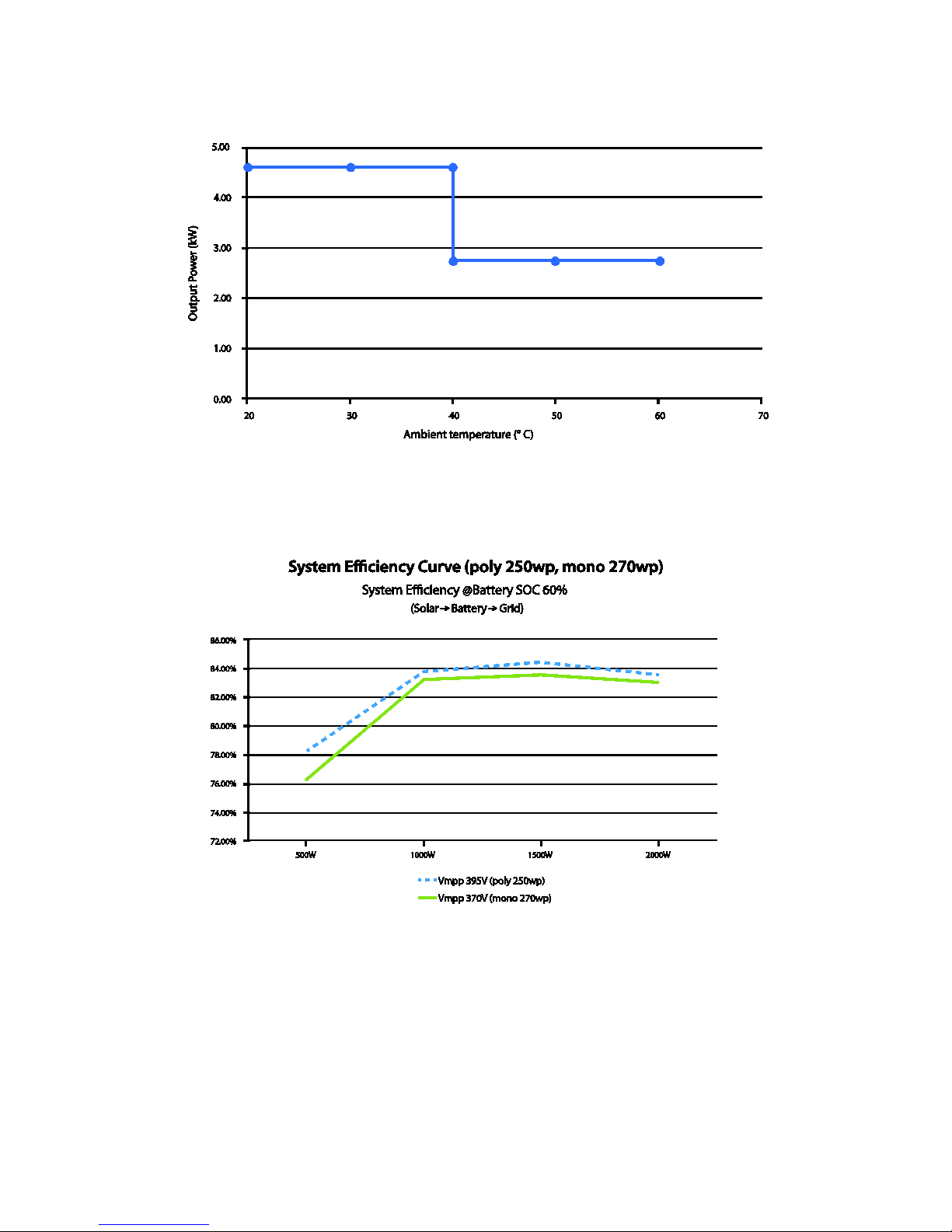
[Figure 2-5: Derating Curve]
[Figure 2-6: Power efficiency curve of System]
Australia (Eng.) 05/2015. Rev1.1 11
 Loading...